Crystal Video Technology 306220180901 Beamink DUO User Manual
Shenzhen Crystal Video Technology Co.,LTD. Beamink DUO Users Manual
User manual

PC:518102 TEL:400-6262-963
TEL:+ 86-755-26716688 FAX:+ 86-755-29188427
E-mail:Sales@cv-hd.com E-mail:Marketing@cv-hd.com
BeamLink-Quad ONE-YEAR LIMITED WARRANTY
BeamLink-Duo Wireless
Transmission System
Quick Start Guide
Version:1.0
Thank you for buying CVW product--BeamLink-Quad,
the 2 Transmitters-to-1 Receiver wireless HD video
transmission system. Please read the instructions
carefully before using the product.
PRODUCT FEATURES
Support 2 Tx-to-1 Rx; tally function; support 2 channels HD
video transmission simultaneously in ONLY 1 RF channel;
8Mbps date rate for each video channel, support 2 channels
video transmission simultaneously in up to 500 meters
range with 150mS latency;
Support 2 channels video input & output through SDI or
HDMI interface. The system can be connected seamlessly
to most popular video switch consoles.
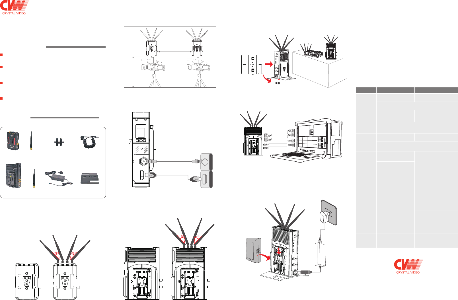
2. Please fix the transmitter via the screw at the bottom or the
V-mount at the back, and place it at a height of around 1.5 to
2 meters above floor. Please make sure that the distance
between each transmitter is more than 1 meter.
2. Please place the receiver at a height of around 1.5 to 2 meters
above floor. Receiver can be placed in vertical or horizontal
positions, and can be fixed via the screw at the bottom or
V-mount at the back. Please install the affiliated metal stand
before placing the receiver in vertical position.
Place the receiver at a
height of around 1.5 to
2 meters above floor.
B: Vertical placement
A: Horizontal placement
Power up and start to use
Please turn on transmitter, receiver and other related devices
in turn. After powering on, the OLED panel on the transmitter
and the receiver will be lit up, and the status light of transmitter
will be lit red. When transmitter and receiver are on connecting
mode, the status light of transmitter will turn to flicker in yellow.
When the connection is successful, the status light of transmitter
will be on yellow steadily, then you will get live image at the
receiver side. It will take about 90 seconds from powering up
the product to the live image displaying.
There is a one-to-one correspondence between four transmitters
and four video output interfaces of the receiver, that is to say,
the video transmitted by the transmitter which shows No. 1 on
its OELD screen will be also output from the video out interface
marked No. 1 and can deduce the rest 3 transmitters from this.
Description of buttons operation
H D M I
S D I H D M I
Antenna
* 8 pieces
1/4 inch screw &
nut connector*2 pieces
Antenna
* 4 pieces Power adapter*1 piece Metal Stand*1 piece
Receiver
*
2
pieces
Transmitter
*
1
piece
HDMI In
SDI In
install the
affiliated metal stand
Power
Usage
Scenario Transmitter Receiver
Long press button “LNA ON/
OFF” for 3 seconds to switch
high or low gain mode.
www.cv-hd.com
--
--
--
Simple installation; convenient operation; flexible application;
eliminate the hassel of running wires across multi-camera
positions.
PACKING LIST
The following items are included in the product package:
Power supply cable
*2 pieces
Notice: The transmitter comes with the Sony NP-F type battery
plate and has preassembled V-mount connector. The receiver
has preassembled battery plate and v-mount connector.
Transmitter Installation
1. Please install all the antennas on the transmitter and make
them in a fan shape as shown in the picture.
3. Please connect the transmitter and camera with SDI or
HDMI cable.
Receiver Installation
1. Please install all the antennas on the receiver, and make them
in a fan shape as shown in the picture.
3. Please connect the receiver and video switch console or
monitor with SDI or HDMI cable.
4. The receiver can be powered by both the
and DC-IN port via the affiliated power adapter. If the mentioned
two types of powersupply are connected at the same time,
the lithium battery should be prioritized in power supplying,
and the battery will switch to the power adapter for power
supplying automatically after the battery power is exhausted.
V-mount battery
This system supports tally function. When the receiver is
activated by low-level current, the transmitter will output
high-level current signal.
Short press button “CH/WPS” to
switch among 11 channels circularly.
After switching the channel, the OLED screen of transmitter and
receiver will both display current working frequency.
Please choose
low gain mode
when works in
short distance.
Switching
to a different
channel when
there is
interference.
After switching into low gain mode both on transmitter and
receiver sides, the OLED screen will display an “L” letter.
If switching back to high gain mode, the letter will disappear.
Please re-pair
the kits after
you replace
receiver or
transmitter
Long press button “CH/WPS”
for 3 seconds to start paring.
Long press button “CH/WPS”
for 3 seconds to start paring.
When transmitter and receiver are in the process of paring,
the OLED screen will display character string “WPS”,
and the character string will disappear after paring is successful.
Reset video
encoder
Long press button “RESET”
for 3 seconds to reset the
video encoder of transmitter.
When the video encoder is on
resetting, the OLED screen of
this transmitter will keep
displaying the character
string “RESET”, and the
character string will disappear
after resetting is finished.
Reset specific
video decoder
on receiver.
First, short press button“RESET”
to choose the video decoder
which you need to reset from the
symbol as 1, 2, on OLED screen of
receiver , then long press button
“RESET” for 3 seconds to confirm
resetting.
When video decoder is in the
process of resetting, the OLED
screen of receiver will keep
displaying character string
“RESET”, and the character
string will disappear after
esetting is finished.
Switch OLED
display direction
of receiver
Short press button “LNA ON/OFF”
and the OLED display direction of
receiver will be switching between
horizontal and vertical modes.
--
Long press button “LNA ON/
OFF” for 3 seconds to switch
high or low gain mode.
Li-battery
Distance> 1 m
Transmitter at a height
of around 1.5 to2
meters above floor.
00:00:00
HD M IHD M I
SD I
HD M IHD M I SD I SD I
HDMI Out
SDI Out
SDI Out
HDMI Out
FCC Warnning:
This equipment has been tested and found to comply with the limits for a Class B digital device,
pursuant
to part 15 of the FCC Rules. These limits are designed to provide reasonable protection against
harmful interference in a residential installation. This equipment generates, uses and can radiate
radio frequency energy and, if not installed and used in accordance with the instructions, may
cause harmful interference to radio communications. However, there is no guarantee that
interference will not occur in a particular installation. If this equipment does cause harmful
interference to radio or television reception, which can be determined by turning the equipment
off and on, the user is encouraged to try to correct the interference by one or more of the following
measures:
• Reorient or relocate the receiving antenna.
• Increase the separation between the equipment and receiver.
• Connect the equipment into an outlet on a circuit different from that to which the receiver is connected.
• Consult the dealer or an experienced radio/TV technician for help.
Caution: Any changes or modifications to this device not explicitly approved by manufacturer could void
your authority to operate this equipment.
This device complies with part 15 of the FCC Rules. Operation is subject to the following two conditions:
(1)This device may not cause harmful interference, and (2) this device must accept any interference
received, including interference that may cause undesired operation.
This equipment complies with FCC radiation exposure limits set forth for an uncontrolled environment.
This equipment should be installed and operated with minimum distance 20cm between the radiator
and your body.