Crystal Video Technology CB662020120206 wireless high-definition receiver User Manual
Shenzhen Crystal Video Technology Co.,LTD. wireless high-definition receiver Users Manual
UserManual.wiki
>
Crystal Video Technology
>
CB662020120206 User Manual
Users Manual
Navigation menu
Upload a User Manual
Namespaces
Wiki Guide
HTML
PDF
Info
Views
User Manual
Discussion / Help
Navigation
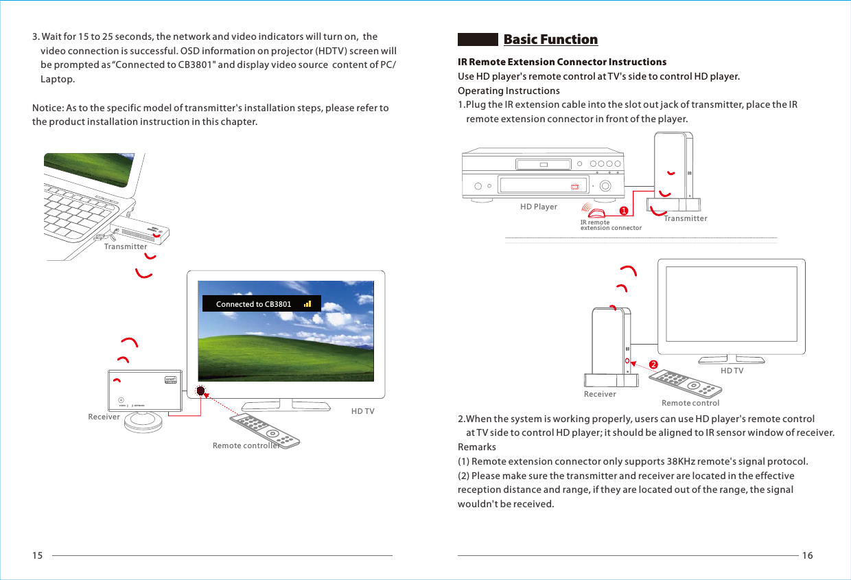
![19 20NNEETTWWOORRKKVVIIDDEEOOTX2:CB8801WStick0203TX3:CWSONY BDB2601TX1:CV6608WDVBRX2:CV3801WRX1:CV6620WHDTV1HDTV2VIDEONETWORKH1V2Connected to Stick0203 Adding Stick0203Press OK to continue or Exit to cancel2TransmitterTransmitterSetupRemove Video SourceModify Video SourceAdd new Video SourceReceiverWHDI Remote Control1Adding Stick0203... Connected to Stick0203 VIDEO NETWORK5. Wait for 15 to 25 seconds, the network and video indicators will turn on, the OSD information on TV screen will be prompted as the following picture and the disappear in 3 seconds.6. You can use WHDI remote control to select different transmitter (player) OK112233MENUEXITSOURCEDELETEADD GUESTINPUT DEVICESWHDI Remote Control1 .MENU2 .EXIT3. SOURCE4. Direction key5. OK6. DELETE7. ADD 8. GUEST9. 1st Video source10. 2nd Video source11. 3nd Video source 112233OOKK1. Enter the main menu2. Return to previous menu3. ENTER [Select Video Source]4. Operate for up, down, left and right directions on the menu screen5. Press OK to confirm the operation6. Enter [Remove Video Source] 7. Enter [Add New Video Source] 8. System powering down9. Connect to 1st Video source10. Connect to 2nd Video source11. Connect to 3nd Video sourceAdd New Video Source (WHDI Product Code Matching)WHDI supports multiple transmitters with one receiver. You can add additional transmitters as refer to the following steps:1. Press [MENU] key of the WHDI remote control to enter the main menu, press direction key to enter [Add new Video Source] or press [Add] key to add video source. Please make sure that the remote control is pointing to receiver's IR sensor window at the operation process.2. Press the code key of transmitter for 3~5 seconds and then loosen from the code key, OSD information will be prompted as “Please Activate Registration On Transmitter Unit”.5. If there need to add more new video source, please repeat the above 1 to 4 steps.3. Press [OK] key to enter the code matching process.4. The code matching will be completed after about 30 seconds, and the video source will be connected to automatically.WHDI Remote Control Operation InstructionPress the code keys simultaneously for 3~5 Sec](https://usermanual.wiki/Crystal-Video-Technology/CB662020120206/User-Guide-1658345-Page-12.png)
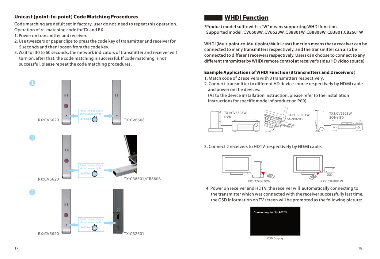
![21 22Removing Stick0203Press OK to continue or Exit to cancelRemoving Stick0203.. SetupRemove Video SourceModify Video SourceAdd new Video SourceSelect Video Source WHDI Remote Control2. Use [UP]/[DOWN] direction keys to choose a video source, press [OK] key to confirm connecting to the one selected.1. Press [Source] key, the list of video sources will be displayed on screen. Remove Video SourceQuick Connect to Video SourceSetupAdd new Video SourceModify Video SourceDisconnect Wireless LinkRemove Video SourceChoose Source To RemoveStick0203Select Video SourceSONY BDDVBSetupStick0203Connected to Stick0203 Rename Video SourcePowering Down..Power Down ModeSelect Video SourceSONY BDDVBSetupStick0203Rename Video Sourceitck0203RChoose Source To RenameSONY BDDVBStick0203SetupAdd new Video SourceRemove Video SourceModify Video SourceWireless Off1. Press [1] key of input devices to connect directly to the 1st video source in the source list; Press [2]/[3] key to connect directly to 2nd/3rd video source in the source list.1. Choose [Remove Video Source] on the main menu or press [DELETE] key to enter [Remove Video Source] menu.quick2. Select the video source wanted be deleted from the video source list.3. press [DELETE] key 5. The video source is removed, return to main menu.4. Press [ok] to Remove 1. Press [MENU] key and choose "Modify Video Source " from main menu.2. Select the video source needed renaming from the video source list and press [OK] to confirm.3. Use [LEFT ][RIGHT]direction keys to change cursor position Use [UP][DOWN] to modify the content of the character 4. Press [OK] to save the modified name.1. After pressing [GUEST ] key, system will enter power down mode.2. Press [GUEST] again to resume work.1. When receiver disconnect from transmitter and there is not any operation to run, the system will turn into Standby Mode, and the OSD information will be prompted as “Wireless Off”.2. Press [SOURCE] or [MENU] key to resume work.Standby Mode](https://usermanual.wiki/Crystal-Video-Technology/CB662020120206/User-Guide-1658345-Page-13.png)