Cub Cadet 3235 Operators Manual
3235 to the manual 7d31cf08-0dff-4012-ab2e-9f0b4dd62b4f
2015-01-05
: Cub-Cadet Cub-Cadet-3235-Operators-Manual-163733 cub-cadet-3235-operators-manual-163733 cub-cadet pdf
Open the PDF directly: View PDF ![]() .
.
Page Count: 1

IMPORTANT: READ SAFETY RULES AND INSTRUCTIONS CAREFULLY
Warning
: This unit is equipped with an internal combustion engine and should not be used on or
near any unimproved forest-covered, brush-covered or grass-covered land unless the engine’s
exhaust system is equipped with a spark arrester meeting applicable local or state laws (if any). If a
spark arrester is used, it should be maintained in effective working order by the operator. In the State
of California the above is required by law (Section 4442 of the California Public Resources Code).
Other states may have similar laws. Federal laws apply on federal lands. A spark arrester for the
muffler is available through your nearest engine authorized service dealer or contact the service
department, P.O. Box 361131 Cleveland, Ohio 44136-0019.
CUB CADET LLC P.O. BOX 361131 CLEVELAND, OHIO 44136-0019 [www.cubcadet.com]
ECO FORM NO. 770-10520B
(1/03)
OPERATOR’S MANUAL
3000
TRACTOR
Model 3235
2
TABLE OF CONTENTS
PAGE
TRACTOR PREPARTION . . . . . . . . . . . . . . . . . . . . . . . . . . . . . . . . . . . . . . 2
IMPORTANT SAFE OPERATION PRACTICES . . . . . . . . . . . . . . . . . . . . . 3
CALLING SERVICE INFORMATION . . . . . . . . . . . . . . . . . . . . . . . . . . . . . . 7
FINDING YOUR MODEL & SERIAL NUMBER . . . . . . . . . . . . . . . . . . . . . . 7
SAFETY LABELS FOUND ON YOUR UNIT . . . . . . . . . . . . . . . . . . . . . . . . 8
CONTROLS . . . . . . . . . . . . . . . . . . . . . . . . . . . . . . . . . . . . . . . . . . . . . . . . . 9
OPERATION . . . . . . . . . . . . . . . . . . . . . . . . . . . . . . . . . . . . . . . . . . . . . . . . 14
ADJUSTMENTS . . . . . . . . . . . . . . . . . . . . . . . . . . . . . . . . . . . . . . . . . . . . . 17
MAINTENANCE . . . . . . . . . . . . . . . . . . . . . . . . . . . . . . . . . . . . . . . . . . . . . 19
LUBRICATION ILLUSTRATION . . . . . . . . . . . . . . . . . . . . . . . . . . . . . . . . . 20
ENGINE INFORMATION . . . . . . . . . . . . . . . . . . . . . . . . . . . . . . . . . . . . . . 27
TROUBLE SHOOTING . . . . . . . . . . . . . . . . . . . . . . . . . . . . . . . . . . . . . . . . 33
OPTIONAL EQUIPMENT . . . . . . . . . . . . . . . . . . . . . . . . . . . . . . . . . . . . . . 35
SPECIFICATIONS . . . . . . . . . . . . . . . . . . . . . . . . . . . . . . . . . . . . . . . . . . . 36
SLOPE GAUGE . . . . . . . . . . . . . . . . . . . . . . . . . . . . . . . . . . . . . . . . . . . . . 37
LIMITED WARRANTY — COMMERCIAL USE . . . . . . . . . . . . . . . . . . . . . 39
LIMITED WARRANTY — RESIDENTIAL USE . . . . . . . . . . . . . . . . . . . . . 41
QUICK REFERENCE PARTS . . . . . . . . . . . . . . . . . . . . . . . . . . . . . . . . . . 44
SECTION 1: TRACTOR PREPARATION
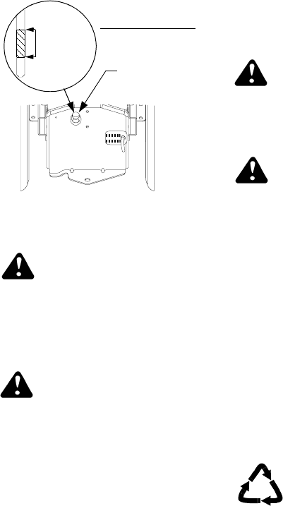
Connect the Battery
Battery posts, terminals and
related accessories contain
lead and lead compounds.
Wash hands after handling.
The tractor is shipped with a sealed
battery, with the positive battery cable
factory connected. The negative cable
must be connected.
Note: Make sure the ignition switch is
in the "OFF" position before attaching
the battery cables.
• Open the tractor hood. Remove the
upper bulkhead baffle from the front of
the dash panel by lifting upward on
the baffle locking tab on each side.
• Remove the protective cap from the
negative terminal of the battery.
• Connect the black battery cable to
the negative battery post. Slide
terminal cover over the connection
and reinstall the upper baffle.
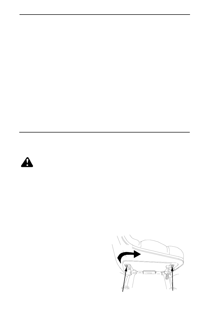
Positon the High Back Seat
For shipping purposes the seat is
installed sideways. Reposition the seat
as follows:
• Remove from the seat the two
screws NOT fastening the seat to
the hinge brackets.
• Loosen the RH screw and remove
the LH screw from the seat and
hinge bracket.
• Rotate the rear of the seat to the
right and align the four front seat
holes with matching holes in the LH
and RH hinge brackets.
• Temporarily install the three previ-
ously removed screws into the three
open front seat holes.
• See Section 8: Adjustments for final
seat adjustment procedures.
Loosen Screw
Remove Screw
Rotate

3
1. GENERAL OPERATION
• Read, understand, and follow all
instructions in the operator’s manual
and on the machine before starting.
Keep this manual in a safe place for
future and regular reference and for
ordering replacement parts.
• Only allow responsible individuals
familiar with the instructions to oper-
ate the machine. Know controls and
how to stop the machine quickly.
• Do not put hands or feet under
cutting deck or near rotating parts.
• Clear the area of objects such as
rocks, toys, wire, etc., which could
be picked up and thrown by the
blade. A small object may have
been overlooked and could be
accidentally thrown by the mower in
any direction and cause injury to
you or a bystander. To help avoid a
thrown objects injury, keep children,
bystanders and helpers at least 75
feet from the mower while it is in
operation. Always wear safety
glasses or safety goggles during
operation or while performing an
adjustment or repair, to protect eyes
from foreign objects. Stop the
blade(s) when crossing gravel
drives, walks or roads.
• Be sure the area is clear of other
people before mowing. Stop
machine if anyone enters the area.
• Never carry passengers.
• Disengage blade(s) before shifting
into reverse and backing up. Always
look down and behind before and
while backing.
• Be aware of the mower and
attachment discharge direction and
do not point it at anyone. Do not
operate the mower without either
the entire grass catcher or the chute
guard in place.
• Slow down before turning. Operate
the machine smoothly. Avoid erratic
operation and excessive speed.
SECTION 2: IMPORTANT SAFE OPERATION PRACTICES
WARNING: THIS SYMBOL POINTS OUT IMPORTANT SAFETY
INSTRUCTIONS WHICH, IF NOT FOLLOWED, COULD ENDANGER
THE PERSONAL SAFETY AND/OR PROPERTY OF YOURSELF AND
OTHERS.READ AND FOLLOW ALL INSTRUCTIONS IN THIS MANUAL
BEFORE ATTEMPTING TO OPERATE YOUR UNIT. FAILURE TO
COMPLY WITH THESE INSTRUCTIONS MAY RESULT IN PERSONAL
INJURY. WHEN YOU SEE THIS SYMBOL, HEED ITS WARNING.
WARNING: The engine exhaust, some of its constituents, and
certain vehicle components contain or emit chemicals known to the State
of California to cause cancer, birth defects or other reproductive harm.
DANGER: Your lawn mower was built to be operated according to the
rules for safe operation in this manual. As with any type of power
equipment, carelessness or error on the part of the operator can result in
serious injury. This lawn mower is capable of amputating hands and feet
and throwing objects. Failure to observe the following safety instructions
could result in serious injury or death.
4
•Never leave a running machine
unattended. Always turn off blade(s),
place transmission in neutral, set
park brake, stop engine and remove
key before dismounting.
•Turn off blade(s) when not mowing.
•Stop engine and wait until blade(s)
comes to a complete stop before (a)
removing grass catcher or
unclogging chute, or (b) making any
repairs, adjusting or removing any
grass or debris.
•Mow only in daylight or good
artificial light.
•Do not operate the machine while
under the influence of alcohol or
drugs.
•Watch for traffic when operating
near or crossing roadways.
•Use extra care when loading or
unloading the machine into a trailer
or truck. This unit should not be
driven up or down a ramp onto a
trailer or truck under power,
because the unit could tip over,
causing serious personal injury. The
unit must be pushed manually on a
ramp to load or unload properly.
•Never make a cutting height
adjustment while engine is running if
operator must dismount to do so.
•Wear sturdy, rough-soled work shoes
and close-fitting slacks and shirts. Do
not wear loose fitting clothes or
jewelry. They can be caught in
moving parts. Never operate a unit in
bare feet, sandals, or sneakers.
•Check overhead clearance carefully
before driving under power lines,
wires, bridges or low hanging tree
branches, before entering or leaving
buildings, or in any other situation
where the operator may be struck or
pulled from the unit, which could
result in serious injury.
•Disengage all attachment clutches,
thoroughly depress the brake pedal,
and shift into neutral before
attempting to start engine.
•Your mower is designed to cut
normal residential grass of a height
no more than 10". Do not attempt to
mow through unusually tall, dry grass
(e.g., pasture) or piles of dry leaves.
Debris may build up on the mower
deck or contact the engine exhaust
presenting a potential fire hazard.
•Use only accessories approved for
this machine by the manufacturer.
Read, understand and follow all
instructions provided with the
approved accessory.
2. SLOPE OPERATION
Slopes are a major factor related to
loss of control and tip-over accidents
which can result in severe injury or
death. All slopes require extra caution.
If you cannot back up the slope or if
you feel uneasy on it, do not mow it.
For your safety, use the slope gauge
included as part of this manual to
measure slopes before operating this
unit on a sloped or hilly area. If the
slope is greater than 15° as shown on
the slope gauge, do not operate this
unit on that area or serious injury
could result.
DO:
•Mow up and down slopes, not
across.
•Remove obstacles such as rocks,
limbs, etc.
•Watch for holes, ruts or bumps.
Uneven terrain could overturn the
machine. Tall grass can hide
obstacles.
•Use slow speed. Choose a low
enough gear so that you will not
have to stop or shift while on the
slope. Always keep machine in gear
when going down slopes to take
advantage of engine braking action.
•Follow the manufacturers
recommendations for wheel weights
or counterweights to improve
stability.
5
•Use extra care with grass catchers
or other attachments. These can
change the stability of the machine.
•Keep all movement on the slopes
slow and gradual. Do not make
sudden changes in speed or
direction. Rapid engagement or
braking could cause the front of the
machine to lift and rapidly flip over
backwards which could cause
serious injury.
•Avoid starting or stopping on a
slope. If tires lose traction,
disengage the blade(s) and proceed
slowly straight down the slope.
DO NOT:
•Do not turn on slopes unless
necessary; then, turn slowly and
gradually downhill, if possible.
•Do not mow near drop-offs, ditches
or embankments. The mower could
suddenly turn over if a wheel is over
the edge of a cliff or ditch, or if an
edge caves in.
•Do not mow on wet grass. Reduced
traction could cause sliding.
•Do not try to stabilize the machine
by putting your foot on the ground.
•Do not use grass catcher on steep
slopes.
3. CHILDREN
•Tragic accidents can occur if the
operator is not alert to the presence
of children. Children are often
attracted to the machine and the
mowing activity. Never assume that
children will remain where you last
saw them.
•Keep children out of the mowing
area and in watchful care of an adult
other than the operator.
•Be alert and turn machine off if
children enter the area.
•Before and when backing, look
behind and down for small children.
•Never carry children, even with the
blades off. They may fall off and be
seriously injured or interfere with the
safe machine operation.
•Never allow children under 14 years
old to operate the machine. Children
14 years and over should only
operate machine under close
parental supervision and proper
instruction.
•Use extra care when approaching
blind corners, shrubs, trees or other
objects that may obscure your vision
of a child or other hazard.
•Remove key when machine is
unattended to prevent unauthorized
operation.
4. SERVICE
•Use extreme care in handling
gasoline and other fuels. They are
extremely flammable and the vapors
are explosive.
•Use only an approved container.
•Never remove fuel cap or add fuel
with the engine running. Allow
engine to cool at least two minutes
before refueling.
•Replace fuel cap securely and wipe
off any spilled fuel before starting
the engine as it may cause a fire or
explosion.
•Extinguish all cigarettes, cigars,
pipes and other sources of ignition.
•Never refuel the machine indoors
because fuel vapors will accumulate
in the area.
•Never store the fuel container or
machine inside where there is an
open flame or spark, such as a gas
hot water heater, space heater or
furnace.
•Never run a machine inside a closed
area.

6
•To reduce fire hazard, keep the
machine free of grass, leaves or
other debris build-up. Clean up oil or
fuel spillage. Allow machine to cool
at least 5 minutes before storing.
•Before cleaning, repairing or
inspecting, make certain the blade
and all moving parts have stopped.
Disconnect the spark plug wire, and
keep the wire away from the spark
plug to prevent accidental starting.
•Check the blade and engine
mounting bolts at frequent intervals
for proper tightness. Also, visually
inspect blade for damage (e.g.,
excessive wear, bent, cracked).
Replace with blade which meets
original equipment specifications.
•Keep all nuts, bolts and screws tight
to be sure the equipment is in safe
working condition.
•Never tamper with safety devices.
Check their proper operation
regularly. Use all guards as
instructed in this manual.
•After striking a foreign object, stop
the engine, remove the wire from
the spark plug and thoroughly
inspect the mower for any damage.
Repair the damage before restarting
and operating the mower.
•Grass catcher components are
subject to wear, damage and
deterioration, which could expose
moving parts or allow objects to be
thrown. For your safety protection,
frequently check components and
replace with manufacturer’s
recommended parts when
necessary.
•Mower blades are sharp and can
cut. Wrap the blade(s) or wear
gloves and use extra caution when
servicing blade(s).
•Check brake operation frequently.
Adjust and service as required.
•Muffler, engine and belt guards
become hot during operation and
can cause a burn. Allow to cool
down before touching.
•Do not change the engine governor
settings or overspeed the engine.
Excessive engine speeds are
dangerous.
•Observe proper disposal laws and
regulations. Improper disposal
offluids and materials can harm the
environment and the ecology.
•Prior to disposal, determine the
proper method to dispose of waste
from your local Environmental
Protection Agency. Recycling
centers are established to properly
dispose of materials in an
environmentally safe fashion.
•Use proper containers when
draining fluids. Do not use food or
beverage containers that may
mislead someone into drinking from
them. Properly dispose of the
containers immediately following the
draining of fluids.
•DO NOT pour oil or other fluids into
the ground, down a drain or into a
stream, pond, lake or other body of
water. Observe Environmental
Protection Agency regulations when
disposing of oil, fuel, coolant, brake
fluid, filters, batteries, tires and other
harmful waste.
•We do not recommend the use of a
pressure washer or garden hose to
clean your unit. They may cause
damage to electrical components;
spindles; pulleys; bearings; or the
engine. The use of water will result
in shortened life and reduce
serviceability.
WARNING - YOUR RESPONSIBILITY: Restrict the use of
this power machine to persons who read, understand and follow
the warnings and instructions in this manual and on the machine.

7
SECTION 3: CALLING SERVICE INFORMATION
The engine manufacturer is responsible for all engine-related issues with
regards to performance, power-rating, and specifications.
If you have difficulties with the unit, have any question regarding the operation
or maintenance of this equipment, or desire additional information not found in
this manual, contact your dealer. If you need help locating a dealer in your area,
contact the Customer Dealer Referral Line by calling:
1-877-282-8684
Before calling your local dealer, make sure that you have your model and serial
numbers ready.
SECTION 4: FINDING YOUR MODEL & SERIAL NUMBER
This Operator’s Manual is an important part of your new tractor. It will help you
prepare, maintain and safely operate your tractor. Please read and understand
what it says.
Before you prepare your tractor for its first use, please locate the tractor and
engine model plates and copy the information from them into the spaces
provided below. The information on the model plates is very important if you
need help from your dealer or the Cub Cadet customer support department.
Refer to Figure 1.
•The tractor model plate is located on the right frame rail behind the right front
tire.
•The engine identification numbers appear on a decal (or decals) affixed to the
engine shrouding.
Figure 1
www.cubcadet.com
CUB CADET LLC
P. O. BOX
361131
CLEVELAND, OH 44136
DEALER LOCATOR PHONE NUMBER:
877-282-8684
Model Number Mfg. Date
XXXXXXXXXXX XXXXXXXXXX
Engine Model No. Engine Spec. No. Engine Serial No.
Model Number Mfg. Date (Serial No.)
8
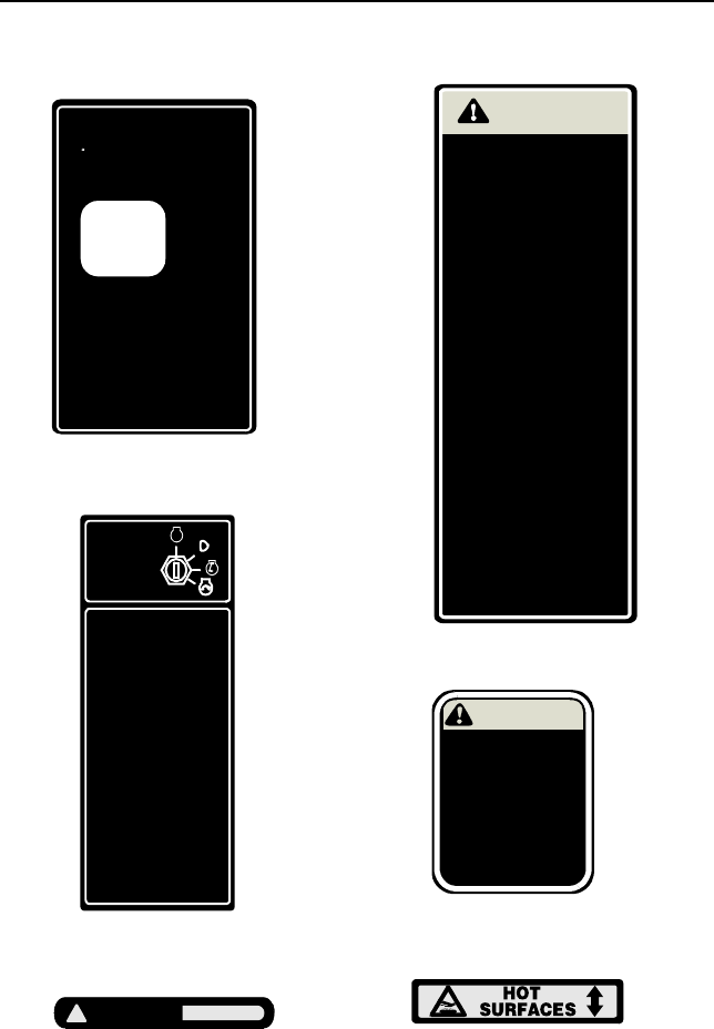
SECTION 5: SAFETY LABELS FOUND ON YOUR UNIT
Figure 2
AVOID
SERIOUS INJURY
OR DEATH
READ OPERATOR'S MANUAL
WARNING
GO UP AND DOWN
SLOPES, NOT ACROSS.
AVOID SUDDEN TURNS.
DO NOT OPERATE UNIT
WHERE IT COULD SLIP
OR TIP.
IF MACHINE STOPS
GOI N G UPHILL, STOP PTO
AND BACK DOWN HILL
SLOWLY.
DO NOT MOW WHEN
CHILDREN OR OTHERS
ARE AROUND.
NEVER CARRY CHILDREN.
LOOK DOWN AND
BEHIND BEFORE AND
WHILE BACKING.
KEEP SAFETY DEVICES
[GUARDS, SHIELDS,
AND SWITCHES] IN
PLACE AND WORKING.
REMOVE OBJECTS THAT
COULD BE THROWN BY
THE BLADES.
KNOW LOCATION AND
FUNCTION OF ALL CONTROLS.
BE SURE THE BLADES AND
THE ENGINE ARE STOPPED
BEFORE PLACING HANDS
OR FEET NEAR BLADES.
BEFORE LEAVING
OPERATOR'S POSITION,
DISENGAGE PTO, ENGAGE
BRAKE LOCK, SHUT OFF
ENGINE AND REMOVE KEY.
•
•
•
•
•
•
•
•
•
•
•
TO ENSURE SAFE AND
PROPER OPERATION
OF TRANSMISSION,
ONLY USE CUB CADET
DRIVE SYSTEM
FLUID PLUS.
737-3120 - 1 QUART
737-3121 - 1 GALLON
READ OPERATOR'S
MANUAL
WARNING
WARNING
!
HOT AREAS
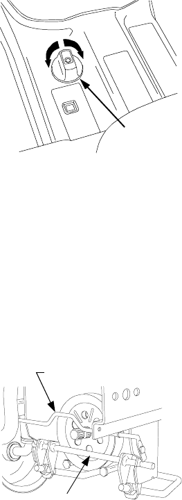
DECK HEIGHT
ADJUSTMENT
(360 Turn Equals 1/2" Adjustment)
POSITION INDICATOR
TURN KNOB CLOCKWISE TO RAISE
DECKSTOP.
LOWER DECK LIFT LEVER UNTIL
POSITION INDICATOR STOPS.
REPEAT PROCESS IF NECESSARY.
TURN KNOB COUNTER CLOCKWISE
TO LOWER DECKSTOP.
RAISE DECK LIFT LEVER UNTIL THE
NUMBER 6 APPEARS IN WINDOW.
1.
2.
3.
4.
5.
STARTING INSTRUCTIONS
STOPPING INSTRUCTIONS
1.BE FAMILIAR WITH CONTROLS
BEFORE STARTING ENGINE
AND OPERATING.
2.SET CHOKE, MOVE THROTTLE
TO MID POSITION AND
DEPRESS BRAKE PEDAL.
3.TURN KEY TO THE START
POSITION.
4.AFTER ENGINE STARTS
OPEN CHOKE.
1.DISENGAGE PTO AND SET
PARKING BRAKE.
2.MOVE THROTTLE CONTROL
TO MID POSITION AND TURN
IGNITION
STOP
KEY OFF
Running Board - Left
Running Board - Center
Front Grille
Running Board - Right
Rear Drawbar
Hood Hinge Bracket
9
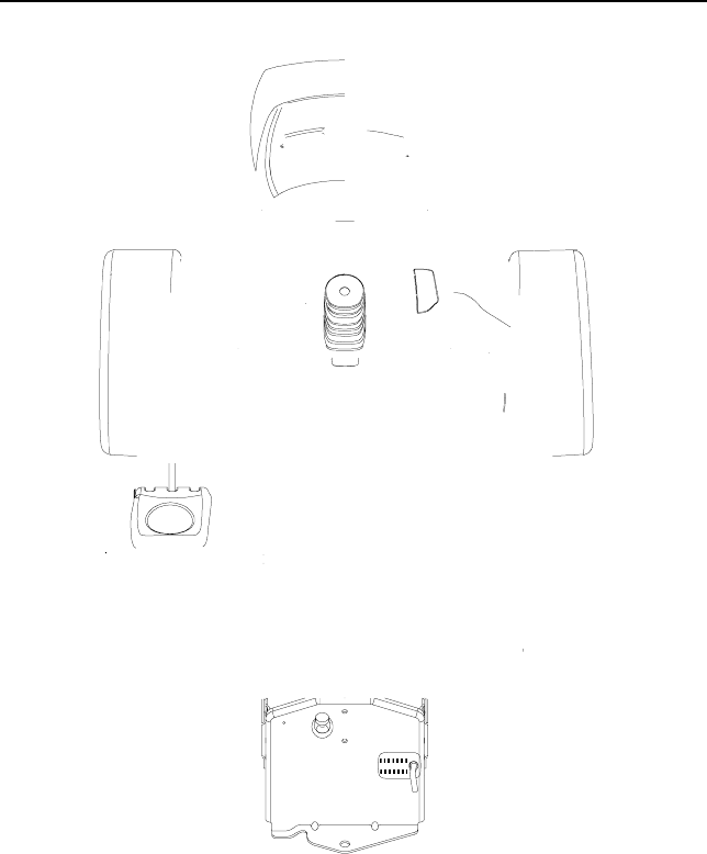
SECTION 6: CONTROLS
Figure 3

10
NOTE: References to LEFT and
RIGHT indicate that side of the tractor
when facing forward while seated in
the drivers seat. Reference to FRONT
indicates the grille end of the tractor;
to REAR, the drawbar end.
Steering Wheel
The steering wheel, centered on the
dash panel, is used to turn the tractor
left or right while driving.
NOTE: This tractor is equipped with
hydraulic power steering. With this
feature, the center of the steering
wheel may not stay center aligned.
Parking Brake Lever
Figure 4
The parking brake lever is located to
the right of the steering wheel on the
dash panel. With the brake pedal
depressed fully, push the parking
brake lever and release the brake
pedal to lock the parking brake.
PTO Switch
The PTO switch is located on the right
side the dash panel. Pull upward on
the right edge of the switch handle to
engage the PTO clutch. Push the
switch downward to disengage the
PTO clutch.
Brake Pedal
Figure 5
The brake pedal is located at the front
of the right running board above the
forward and reverse pedals. Depress
to stop the tractor and disengage the
cruise control. Fully depress the brake
pedal to activate the safety interlock
switch when starting the tractor.
Depressing the brake pedal will also
engage the transmission differential
lock. Always make certain the diff. lock
disengages when the brake pedal is
released.
Reverse Pedal
Figure 6
NOTE: Check behind the tractor to
be sure the area is clear of people,
pets or obstacles and use a slower
speed to maintain control of the tractor
when traveling in reverse.
The reverse control pedal is located
on the right running board below the
brake pedal. Press the pedal down to
move in reverse.
Forward Pedal
Figure 7
The forward control pedal is located
on the right running board below the
brake pedal. Slowly press down on the
pedal to start moving forward. The
forward ground speed of the tractor is
directly affected by the distance the
pedal is depressed.
Center Lift Height Indicator
The center lift height indicator is
located in the left running board. This
indicator shows the operator the
relative height position setting of the
hydraulic center lift system. The lower
number indicates a lower setting.
11
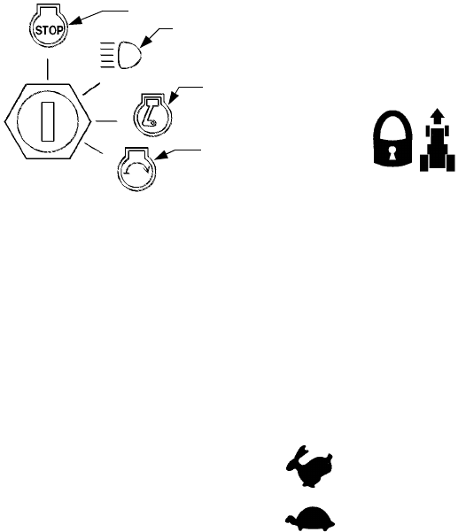
Ignition / Light Switch
To prevent accidental starting and/or
battery discharge, remove the key
from the ignition switch when the
tractor is not in use. The combination
lights and ignition switch has four
positions. See Figure 8 for a
description of each position.
Figure 8
Transmission Release Rod
The transmission release rod is
located at the back of the tractor in the
draw bar. This rod, when engaged,
allows the tractor to be pushed short
distances by hand.
To disengage the transmission, pull
back on the rod until its locking flange
is visible outside the drawbar, then
lower the rod into the slot and release.
To reengage the transmission, pull
back on the rod, lift out of the slot and
release.
Transmission Oil Fill/Dipstick
The transmission oil fill/dipstick is
located at the back of the tractor in the
rear draw bar. The handle of the
transmission oil dipstick serves as
the fill tube plug and should fit snugly
in the fill tube.
Fuel Fill Cap
The fuel fill cap is located on the
fender to the left of the seat.
Cup Holder
The cup holder is located on the
fender to the left of the seat.
Hydraulic Lift Lever
The hydraulic lift lever is located on
the fender to the left of the seat. This
lever is used to operate the tractor’s
center lift system.
Steering Wheel Tilt Lock
The steering wheel tilt lock is located
below the steering wheel in the dash
panel. Press downward to release.
Cruise Control Lever
Figure 9
The cruise control lever is located to
the left of the steering wheel. Push the
cruise control lever downward while
traveling at the desired forward speed
to engage the cruise control.
Choke Lever
The choke lever is located to the left of
the steering wheel in the throttle/choke
lever pod. Push the lever forward to
close the engine choke plate.
Throttle Lever
The throttle lever is located to the left of
the steering wheel in the throttle/choke
lever pod. When set in a given position,
the throttle lever will maintain a uniform
engine speed. Push the lever forward to
increase the engine speed.
IMPORTANT: When using power
take-off operated equipment, best
performance is achieved with the
throttle lever in the “FAST” position.
Off
On/Lights
On
Start
This symbol shows the fast
This symbol shows the slow
position.
position
12
Seat Adjustment Lever
The seat adjustment lever is located
below the seat. This lever is used to
adjust the seat forward or backward.
Differential Lock Pedal
Located at the front of the left running
board. Depressing the diff. lock pedal
engages the transmission differential
lock, which improves traction at the rear
wheels when operating on uneven ter-
rain or in slippery conditions. However,
use care when engaging the diff. lock
on manicured turf where sharp turns
are required. Damage to the turf could
occur.
Depressing the brake pedal also actu-
ates the diff. lock pedal. Make certain
the diff. lock disengages when the
brake pedal is released.
Deck Height Adjustment Knob
The deck height adjustment knob is
located on the left running board (See
Figure 10). Use this knob to set (and
hold) your desired deckstop position
for the mower deck, regardless of
whether the deck caster wheels
contact the ground.
Each full rotation of the adjustment
knob equals approximately a 1/4 inch
adjustment in the deck height setting,
and there are four detent positions per
rotation.
Always use the tractor lift system to
raise the deck before turning the
adjustment knob.
Figure 10
Deck Front Lift Rod Assembly
For shipping purposes, the deck front
lift rod assembly has been installed on
the tractor. Cut the tie strap holding
the lift rod assembly to the tractor;
then pull downward on the quick latch
rod at the front of the tractor to remove
the lift rod assembly.
Figure 11
RAISE
LOWER
Height
Adjustment
Knob
Quick Latch Rod
Lift Rod Assembly
13
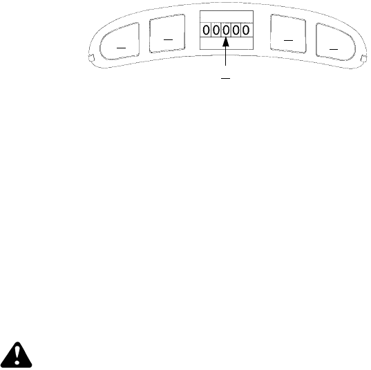
Indicator Light Pod
Figure 12
AB
C
DE
A
B
C
D
E
Oil Pressure Indicator
Low Fuel Indicator
Hour Meter
Not Used
Not Used
Hour Meter
The hour meter is part of the indicator
light pod in the dash panel. The hour
meter operates whenever the ignition
switch is in the “ON” or “ON/LIGHTS”
position. Record the actual hours of trac-
tor operation to ensure all maintenance
procedures are completed according to
the schedule in this manual.
Oil Pressure Indicator
WARNING: Operating the
tractor with low oil level or
low pressure could result in
severe engine damage.
The oil pressure indicator is part of the
indicator light pod on the dash panel.
This indicator will illuminate when the
engine oil pressure is low. If this
indicator illuminates, stop the tractor
immediately and check the engine oil
level. If the oil level is within the
operating range, and the light remains
on, contact your Cub Cadet dealer.
Low Fuel Indicator
The Low Fuel indicator is part of the
indicator light pod on the dash panel.
This indicator will illuminate when the
tractor is low on fuel. If the gas tank is
full and the light stays on, contact your
Cub Cadet dealer.

14
SECTION 7: OPERATION
Safety Interlock Switches
This tractor is equipped with a safety
interlock system for the protection of
the operator. If the interlock system
should ever malfunction, do not
operate the tractor. Contact your
authorized Cub Cadet Dealer. The
safety interlock system prevents the
engine from cranking or starting
unless the brake pedal is fully
depressed, and the PTO is “OFF”.
•The safety interlock system will
automatically shut off the engine if
the operator leaves the seat before
engaging the brake lock.
•The safety interlock system will auto-
matically shut off the engine if the
operator leaves the seat with the PTO
“ON”, regardless of whether the brake
lock is engaged. The PTO switch
must be “OFF” to restart the engine.
•The safety interlock system will
automatically shut off the PTO if the
reverse control pedal is depressed
with the PTO “ON”.
Fueling The Tractor
NOTE:Some fuels, called oxygen-
ated or reformulated gasolines, are
gasoline blended with alcohols or
ethers. Gasolines blended with either
ethyl alcohol (Max. 10%) or methyl ter-
tiary butyl ether (MTBE, Max. 15%)
are approved as fuels for this engine.
If any undesirable operating symp-
toms occur, use gasoline with a lower
percentage of these blends. Do not
use gasoline which contains Methanol
or other alcohol blends. For best
results use only clean, fresh,
unleaded gasoline with an octane rat-
ing of 87 or higher. Purchase fuel in a
quantity that can be used within 30
days to assure fuel freshness. Do not
use gasoline left over from the pevi-
ous season to minimize gum deposits
in the fuel system. Leaded gasoline is
NOT RECOMMENDED. Leaded gaso-
line may be used in areas where
unleaded is not available and exhaust
emissions are not regulated.
Do not fill the fuel tank when the
engine is running or while the engine
is hot. Tighten the fuel cap securely.
Unscrew the fuel cap and fill the fuel
tank from an approved gasoline
container.
Starting The Engine
•Operator must be sitting in the
tractor seat.
•Push choke lever to the full choke
position. Less choking may be
necessary due to variations in
temperature, grade of fuel, etc. Little
or no choking will be needed when
the engine is warm.
•Place the throttle midway between
the “SLOW” and “FAST” position.
•Make sure the PTO switch is in the
“OFF” position.
•Fully depress the brake pedal.
•Turn the ignition key clockwise to
the “START” position and release it
as soon as the engine starts;
however, do not crank the engine
continuously for more than 10
seconds at a time. If the engine
does not start within this time, turn
the key to “OFF” and wait a minute
to allow the engine’s starter motor to
cool. Try again after waiting.
•After the engine starts, slowly
release the brake pedal. As the
engine warms up, gradually pull the
choke lever all the way back. Do not
use the choke to enrich the fuel
mixture, except when necessary to
start the engine.
Stopping The Engine
NOTE: Remove the key from the
ignition switch to prevent accidental
starting or battery discharge if the
equipment is left unattended.
15
•Place the PTO switch in the “OFF”
position. Place the throttle control
lever between the “MID” and “FAST”
positions. Then turn the ignition key
to the “OFF” position and remove
the key from the ignition switch.
Driving The Tractor
WARNING: Avoid sudden
starts, excessive speed and
sudden stops.
WARNING: Do not leave
the seat of the tractor with-
out disengaging the PTO and
engaging the parking brake.
If leaving the tractor unat-
tended, turn the ignition key
off and remove key.
•Depress the brake pedal to release
the parking brake and let the pedal
up. Move the throttle lever to the
position where the engine operates
best for the load to be handled
(normally full throttle).
NOTE: Do not use the forward or
reverse control pedals to change the
direction of travel when the tractor is in
motion. Use the brake pedal to bring the
tractor to a stop before depressing either
the forward or reverse control pedal.
•To move forward, slowly depress
the forward control pedal until the
desired speed is achieved.
•To move in reverse, check that the
area behind is clear then slowly
depress the reverse control pedal.
Setting The Cruise Control
NOTE: The cruise control feature
can only be operated in the forward
direction.
•Slowly depress the forward control
pedal until the desired speed is
achieved.
•Lightly push the cruise control lever
downward.
•While continuing to hold the cruise
lever down, lift your foot from the
forward control pedal (you should
feel the cruise latch engage).
•If properly engaged, the cruise lever
and forward control pedal should
lock in the down position, and the
tractor will maintain the same
forward speed.
•Disengage the cruise control using
one of the following methods:
- Depress the brake pedal to
disengage the cruise control
and stop the tractor.
- Lightly depress the forward control
pedal.
- Lift the cruise control lever upward.
NOTE:
16
Avoid stopping when driving up a
slope. If it is necessary to stop while
driving up a slope, start up smoothly
and carefully to reduce the possibility
of flipping the tractor over backward.
Stopping The Tractor
Fully depress the brake pedal to bring
the tractor to a complete stop, engage
the parking brake, disengage the
PTO, turn the ignition switch to “OFF’”
and remove the key from the switch
before dismounting.
Using the Hydraulic Lift System
To raise an attachment using the
hydraulic lift system, the engine must
be running. Generally, an attachment
can be lowered with the engine
running or off. Push the hydraulic lift
lever forward to lower an attachment
or pull the hydraulic lift lever back to
raise an attachment.
Opening Tool Box
A convenient tool box and manual
pouch is located under the seat. To
access this area, pivot the seat forward.
Engaging The PTO
•Move the throttle control lever to
approximately mid throttle position.
•Pull the PTO switch to the “RUN”
position.
•Advance the throttle lever to the
operating speed (full engine speed).
•The operator must remain in the
tractor seat at all times. If the
operator should leave the seat
without turning off the PTO switch,
the tractor’s engine will shut off.
IMPORTANT: The PTO clutch can-
not be operated when the tractor is
driving in the reverse direction. The
PTO switch must in the “OFF” position
when the reverse control pedal is
depressed, or the PTO clutch will auto-
matically disengage. To re-engage the
PTO clutch, release the reverse con-
trol pedal, move the PTO switch to the
“OFF” position, then again pull the
switch to the “RUN” position.
Engaging Differential Lock
Fully depress the diff. lock pedal to
lock the transmission differential and
provide constant power to both rear
wheels when increased traction is
needed. Release the diff. lock pedal
when extra traction is not needed.
Depressing the brake pedal also
actuates the diff. lock pedal, resulting in
optimal braking action.
NOTE: Because of the load on the
internal engagement mechanism,
releasing the diff. lock pedal may not
always disengage the differential lock.
It may be necessary to slow the trac-
tor, or reverse the direction of travel, to
disengage the differential lock.
Using The Drawbar
Drawbar equipment must be hitched to
the tractor only at the hitch hole. See
Figure 13.
Figure 13
Mowing
WARNING: To avoid possi-
ble injury, never direct the
discharge of material toward
bystanders or allow anyone
near the machine while in op-
eration. Although the area
has been supposedly cleared
of foreign objects, small ob-
jects may be picked up and
discharged by the mower.
This tractor can be equipped with one
of Cub Cadet’s high quality mowing
decks. The following information will
be helpful when using a Cub Cadet
mowing deck with your tractor.
17
For best results it is recommended that
the first two laps should be cut with the
discharge thrown towards the center.
After the first two laps, reverse the direc-
tion to throw the discharge to the outside
for the balance of cutting. This will give a
better appearance to the lawn.
Do not cut the grass too short, as the
mower will tend to scalp the grass.
Short grass invites weed growth and
yellows quickly in dry weather.
Mowing should be done with the
engine at full throttle. Do not mow at
high ground speed.
During certain times of the year and
under some conditions, the mower
may leave streaks of uncut grass.
Streaking may occur when attempting
to mow heavy weeds and tall grass.
Under these conditions it may be
necessary to go back over the cut
area a second time to get a clean cut.
The following practices will help
eliminate streaking:
•Mow the area more often so the
grass doesn’t get too tall and heavy.
•Operate the tractor at full throttle
and slower forward speeds.
•Keep the blades sharp and replace
the blades when worn.
SECTION 8: ADJUSTMENTS
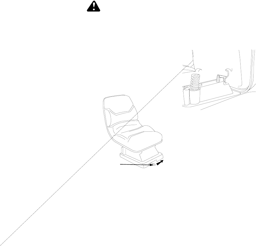
Seat Adjustment
WARNING: Do not adjust
the seat when the tractor is
moving, as this could cause
the operator to lose control
of the tractor.
For the comfort of the operator, an
easy to operate adjustable seat is a
feature of this tractor. Also there are
three seat mounting positions to pro-
vide additional adjustment positions.
To adjust the seat forward or back,
slide the seat adjustment lever to the
left; reposition the seat to your most
comfortable position; and release the
seat adjustment lever. See Figure 14.
Figure 14
If additional adjustment is desired,
remount the seat as follows:
Flip the seat forward and remove the
four screws fastening the seat to the
seat hinge brackets.
Remount the seat on the hinge brack-
ets as follows (See Figure 15):
•Seat forward-use front two holes.
•Seat middle-use middle two holes.
•Seat rearward-use rear two holes
Figure 15
Steering Wheel Tilt Adjustment
WARNING: Do not adjust
the steering wheel when the
tractor is moving, as this
could cause the operator to
lose control of the tractor.
Seat
Adjustment
Lever
18
For the comfort of the operator, this trac-
tor is equipped with an adjustable tilt
steering wheel. To adjust the steering
wheel: push the steering wheel tilt lock
lever downward, move the steering
wheel to the desired position, and
release the steering wheel tilt lock lever.
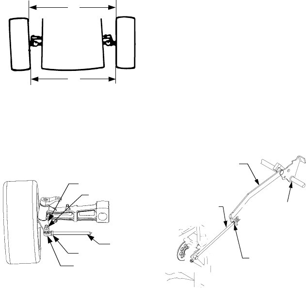
Front Wheel Alignment
Note: The left-hand ball joint is left-
hand threaded.
The front wheels should toe-in approx-
imately 1/8 inch. Measure distances A
and B. A should be approximately 1/8
inch less than B. See Figure 16.
Figure 16
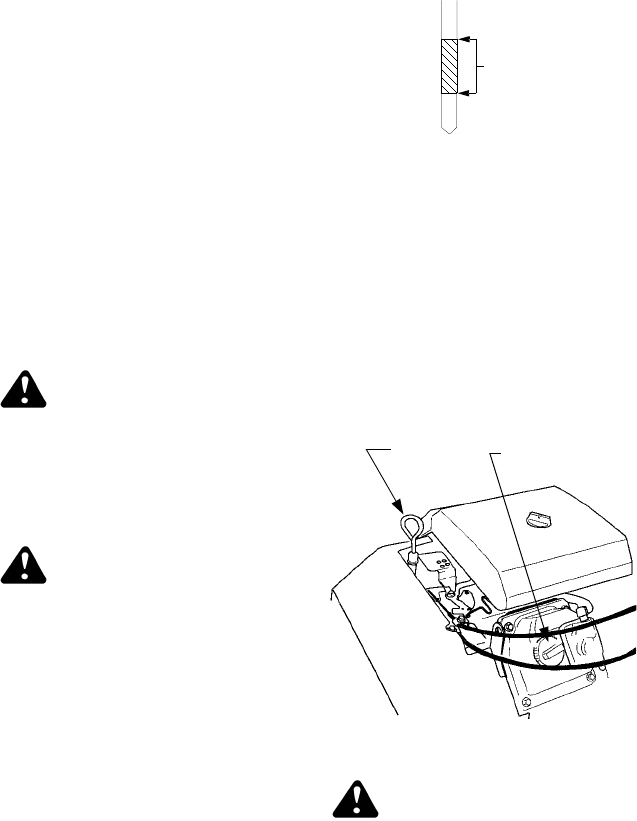
To adjust toe-in, loosen left and right
ball joint jam nuts. See Figure 17.
Turn the tie rod in or out of the ball
joints as required to attain proper
adjustment. Tighten the jam nuts
against the ball joints.
Figure 17
Brake Inspection and Adjustment
During normal operation, the tractor
brake is subject to minimal wear. How-
ever, the brake should be periodically
tested, and adjusted if necessary.
Checking the Brake.
Place the tractor on a firm and level
surface. Stop the engine and remove
the ignition key.
Pull and lock the transmission release
rod in the “Transmission Released”
position. Perform the following checks:
NOTE: The tractor may be difficult to
push because of the hydro transmis-
sion’s braking action.
•Engage the parking brake. If the
tractor can be pushed forward or
rearward, the braking force must be
increased.
•Release the Parking Brake Lever. If
the tractor cannot be pushed
forward or rearward, the braking
force must be decreased.
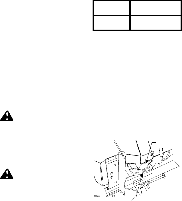
Adjusting the Brake.
Remove the rear drawbar from the
frame by removing the four hex tapp
screws. NOTE: The oil fill tube/dipstick
will be pulled from the transmission
housing. Plug or cover the hole in the
transmission to prevent dirt or debris
from entering.
From beneath the right/rear side of the
tractor frame, secure the hex shaped
flange of the brake rod (located just
behind the brake link) to prevent the
rod from turning (See Figure 18).
Figure 18
A
Front
B
Steering Axle
Hex Lock Nut
Ball Joint
Hex Jam Nut
Tie Rod
VIEWED FROM ABOVE - FENDER
AND RUNNING BOARD REMOVED
Brake Link
Brake Rod Brake Shaft
Hex Shaped
Flange
Assembly
Brake Assembly
(On Transmission)

19
From just above the right axle carrier,
inside the right frame rail, slowly turn
the hex nylon lock nut at the end of
the brake rod as follows to adjust the
brake (Refer to Figure 18):
•Turn the nylon lock nut clockwise to
increase the braking force.
•Turn the nylon lock nut counter-
clockwise to decrease the braking
force.
Recheck the brake adjustment to
ensure proper operation, and readjust
as necessary. If brake adjustment
does not correct the problem, see your
authorized Cub Cadet dealer.
While guiding the transmission release
rod through keyhole and the oil fill
tube/dipstick into the transmission,
position the rear drawbar on the
frame. Secure with the four hex tapp
screws.
Turning Radius Adjustment
This tractor is equipped with hydraulic
power steering which is set at the
factory. The turning radius should be
equal for both left and right hand
turns. If adjustment is necessary
please contact your authorized Cub
Cadet dealer.
SECTION 9: MAINTENANCE
Maintenance Chart
‡Change oil and filter after first 5 hours
†More often under dusty conditions
†† Clean every 25 hours or more often under dusty or dirty conditions
NOTE: We do not recommend the use of a pressure washer or garden hose to
clean your unit. They may cause damage to electrical components; spindles;
pulleys; bearings; or the engine. The use of water will result in shortened life
and reduce serviceability.
Operation to
be performed
Each Use
10 Hours
50 Hours
100 Hours
150 Hours
200 Hours
250 Hours
300 Hours
Grease front wheel bearings •
Grease L/R steering knuckles •
Grease front pivot axle •
Check engine oil level •
Change engine oil and filter ‡ •••
Check spark plug condition •••
Check transmission oil level •
Change transmission oil filter •••••
Change transmission oil ••
Check air cleaner & housing •
Clean & re-oil foam air
pre-cleaner ††
Change air cleaner
paper cartride †††
20
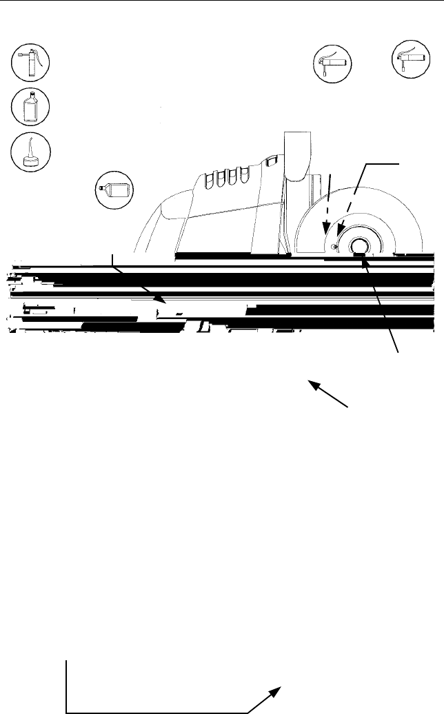
LUBRICATION ILLUSTRATION
Cub Cadet 251H EP Grease
or equivalent No. 2 lithium grease
Engine Oil: See Figure 27 on page 30
Transmission Oil - Cub Cadet Drive
Oil Can (High quality lubricating oil)
System Fluid Plus - ONLY
Engine
Front Pivot Axle
L/R Steering Knuckle
L/R Front Wheels
Foot Control Pivot Points
Transmission
21
Accessing Engine Compartment
The engine compartment can be
accessed by raising the hood as
follows:
•Lift the hood straight upward at the
recessed notches of the side panels
to disengage the internal hood latch.
•Carefully pivot the hood forward to
open.
To close the hood:
•Carefully pivot the hood rearward to
lower.
•Push down on the front of the hood
to engage the internal hood latch.
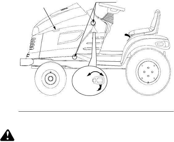
If greater access is required, the
tractor is equipped with quick release
side panels. Remove the quick release
side panels as follows (see Figure 19):
•Open the hood by lifting upward at
the side panel notches on each side
of the tractor.
•Flip the tab of the two quick release
fasteners up and turn to align with the
slots in side panels.
•Swing the rear of the side panel out
and away from the tractor.
•Slide the side panel rearward to
disengage the two front tabs of the
side panel from the slots of the
grille/side panel mounting strip.
To reinstall the side panels:
•Insert the side panel front tabs into
the slots of the grille/side panel
mounting strip.
•Swing the rear of the side panel
inward and align so that the tabs of
the quick release fasteners go
through the side panel slots.
•Pull the quick release fastener tabs
slightly outward and rotate 1/4 turn
(perpendicular to slot) to lock the
side panels in place. Flip the
fastener tabs down.
•Close the hood.
Figure 19
Turn
Flip up
Lift Hood Here Quick Fasteners
General Battery Information
WARNING
•Battery posts, terminals and related
accessories contain lead and lead
compounds. Wash hands after
handling.
•Battery acid must be handled with
great care, as contact with it can
burn and blister the skin. It is
advisable to wear protective clothing
(goggles, rubber gloves and apron)
when working with acid.
•Should battery acid accidentally
splatter into the eyes or onto the
skin, rinse the affected area

22
immediately with clean cold water. If
there is any further discomfort, seek
prompt medical attention.
•If acid spills on clothing, first dilute it
with clean water, then neutralize
with a solution of ammonia/water or
baking soda/water.
•Since battery acid is corrosive, do not
pour it into any sink or drain. Before
discarding an empty electrolyte con-
tainer, rinse it thoroughly with a
neutralizing solution.
•NEVER connect (or disconnect)
battery charger clips to the battery
while the charger is turned on, as it
can cause sparks.
•Keep all sources of ignition
(cigarettes, matches, lighters) away
from the battery. The hydrogen gas
generated during charging can be
combustible.
•As a further precaution, only charge
the battery in a well ventilated area.
• Always shield eyes and protect skin
and clothing when working near
batteries.
WARNING: Batteries contain
sulfuric acid and may emit
explosive gases. Use extreme
caution when handling batter-
ies. Keep batteries out of the
reach of children.
Battery Removal
WARNING: Battery posts,
terminals and related acces-
sories contain lead and lead
compounds. Wash hands
after handling.
The battery is located under the dash
panel in the frame pedestal.
To remove the battery:
•Open the tractor hood by lifting it at
the notches in the side panels.
•Remove the upper bulkhead baffle
from the front of the dash panel by
lifting upward on the baffle locking tab
on each side.
•Pull the upper end of the rubber
battery strap rearward to unhook it
from the tab on the pedestal.
•Loosen the negative battery cable
clamp and disconnect the negative
lead from the battery; then discon-
nect the positive lead from the battery.
•Carefully lift the battery up and out
of the tractor.
Install the battery by repeating the
above steps in the reverse order.
Always connect the positive lead to
the battery before connecting the
negative lead.
Battery Maintenance
The battery is filled with battery acid
and then sealed at the factory.
However, even a “maintenance free”
battery requires some maintenance to
ensure its proper life cycle.
•Spray the terminals and exposed
wire with a battery terminal sealer,
or coat the terminals with a thin coat
of grease or petroleum jelly, to
protect against corrosion.
•The battery should be kept clean.
Any deposits of acid should be
neutralized with baking soda and
water. Be careful not to get this
solution in the cells.
•Avoid tipping. Even a sealed battery
will leak electrolyte when tipped.
Battery Storage
•When storing the tractor for extended
periods, disconnect the battery
cables. Removing the battery from
the unit is recommended.
•All batteries discharge during stor-
age. Keep the exterior of the battery
clean, especially the top. A dirty bat-
tery will discharge more rapidly.
•The battery must be stored with a
full charge. A discharged battery will
freeze at a higher temperature.
Specific GravityFreezing Point
1.265 –71°F
1.250 –62°F
1.200 –16°F
1.150 5°F
1.100 16°F
•Recharge the battery before
returning to service; or every two
months, whichever comes first.
23
Headlight Bulb Replacement
Replace headlight bulbs as follows:
(See Figure 20)
1. After noting which wire connects
to each terminal, unplug the wire
harness leads from the headlight
socket terminals.
2. Rotate the socket assembly as
follows to remove from the
reflector housing:
Figure 20
•Left headlight — appoximately 1/4
turn counterclockwise.
•Right headlight — approximately
1/4 turn clockwise.
3. Push the bulb inward and turn
counterclockwise to remove from
the socket.
4. Align the post of the bulb base
with the notch in the socket, then
push the bulb inward and turn
clockwise to lock
5. With the terminals pointing
upward, align the tab of the
socket with the notch of the
reflector. Push the socket inward
and turn as follows to lock:
•Left headlight-1/4 turn clockwise.
•Right headlight-1/4 turn counter-
clockwise.
6. Connect the wire harness leads to
the appropriate socket terminals.
Tail Light Bulb Replacement
Each tail light assembly has two
lightbulbs. Access the back side of the
tail lights from under the rear fender.
NOTE: Because of the close proximity
of the fuel tank, caution should be
taken when removing the tail light
sockets from the reflector housings.
The bulbs can be pulled from the
sockets and dropped into the reflector
housing, requiring removal of the
reflector housing to retrieve the bulb.
Replace a tail light bulb as follows:
•Turn the light socket counterclock-
wise to align the socket tabs with
the notches in the tail light reflector.
•Once aligned, carefully pull light
socket out of the tail light reflector.
•Pull the light bulb from the socket
and replace with like part.
•Align the tabs of the socket with the
notches in the reflector and carefully
insert the socket. Turn the socket
fully clockwise to lock in place.
Tire Inflation
Keep the tires inflated to the
recommended pressure. Improper
inflation will affect tire life and operator
comfort, and also could affect the level
of the mower deck and quality of cut.
See the tire side wall for proper
inflation range.
Ensure that the valve caps are
securely tightened in place to prevent
air loss and to protect the valve core.
Do not overload the tractor tires by
mounting equipment on the tractor
which exceeds the load capacity of the
size of the tires on the tractor.
Checking Transmission Oil Level
NOTE: Check the oil level only while
the engine is stopped and the tractor
is level.
Check the oil level of the transmission
case before each use to see that it is
filled to the correct level. Before
checking the transmission oil level,
clean the area around the
Transmission Oil Fill/Dipstick to
prevent debris from entering the
transmission case. Always keep the oil
level between the “FULL” and the
“ADD” marks on the dipstick. When
checking the oil level, the dipstick
Terminals
Socket
Reflector Housing
Reflector Notch
Socket Tab
24
must be withdrawn and wiped clean,
then fully reinserted before being
withdrawn again for a true reading.
Figure 21
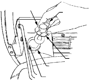
Adding Transmission Oil
WARNING: The fluid for your
transmission has been spe-
cially formulated to ensure
the safe and proper opera-
tion of your tractor. Add Cub
Cadet Drive System Fluid
Plus ONLY. Do not use any
other fluid.
WARNING: Never overfill the
transmission case. Damage
may result if the oil level in the
transmission case is below
the “ADD” mark or over the
“FULL” mark of the dipstick.
For best results, fill to the “FULL” mark
on the dipstick as opposed to adding a
given quantity of oil. Always check the
level on the dipstick before adding
more oil. See Figure 21.
Refer to the Lubrication Illustration for
information regarding the proper type
of oil to add to the transmission case.
See the Specifications Chart for the
quantity required.
•Place the tractor on a level surface and
engage the parking brake. Stop the
engine and remove the ignition key.
•Clean the area around the
Transmission Oil Fill /Dipstick to
prevent debris from entering the
transmission case.
•Remove the dipstick from the oil fill
tube and SLOWLY pour oil into the
oil fill tube. Fill the transmission
case until the oil level reaches the
“FULL” mark on the dipstick.
•Reinstall the dipstick securely into
the oil fill tube.
WARNING: The oil fill plug/
dipstick must be installed
securely into the fill tube at
all times when the engine is
operating.
Changing Transmission Oil
WARNING: The fluid for your
transmission has been spe-
cially formulated to ensure
the safe and proper opera-
tion of your tractor. When
changing the transmission
fluid replace it with Cub
Cadet Drive System Fluid
Plus ONLY. Failure to use
Cub Cadet Drive System
Fluid Plus may result in a fail-
ure of the drive system which
could result in property dam-
age or personal injury. Do
not use any other fluid
See to the Maintenance Chart for the
frequency of service and the Specifi-
cations Chart for the quantity required.
NOTE: Do not reuse the transmission
oil. Contaminated transmission oil can
damage the hydro transmission.
Please dispose of used oil
at appropriate recycling
centers.
•Place the tractor on a level surface
and engage the parking brake. Stop
the tractor’s engine and remove the
ignition key.
•Remove any center attachments.
•Clean the area around the transmis-
sion drain plug to prevent debris
from entering the transmission case.
Remove the drain plug and allow
the transmission oil to drain into a
clean container having a capacity of
more than 5 quarts. Reinstall the
drain plug. See Figure 22.
Transmission
Oil Fill Tube/
Dipstick
F
A
Operating
Range
Dipstick Reading
25
Figure 22
•Clean around the base of the trans-
mission oil filter and remove the
filter by turning it counterclockwise.
•Apply a light coating of clean trans-
mission oil to the gasket of the new
filter. Install the filter by turning it
clockwise, by hand, until the gasket
contacts the filter base on the trans-
mission housing; then tighten the
filter an additional 1/2 turn.
•Clean the area around the
Transmission Oil Fill/Dipstick to
prevent debris from entering the
transmission case.
•Remove the dipstick and SLOWLY
pour oil into the oil fill tube. Fill the
transmission case until the oil level
reaches the “FULL” mark on the
dipstick.
•Reinstall the dipstick securely into
the oil fill tube.
•Start the engine and allow it to run
for a few minutes. Shut the engine
off, then check for leaks and
recheck the oil level in the
transmission case.
Important Information: The service
life and reliability of any machine
depends upon the care it is given.
Proper lubrication is a very important
part of that care. The maintenance
schedule reflects the minimal require-
ments to maintain the equipment.
More frequent inspections and mainte-
nance is preferable.
Using the lubrication illustration as a
guide, make certain that all lubrication
fittings are installed and functioning.
Be sure all fittings are free from dirt
and paint so the lubricant is certain to
enter the bearing.
Using a pressure lubricating gun,
always force the lubricant through the
full length of each bearing until it
emerges at the end, carrying with it
the worn lubricant and any dirt that
may have entered the bearing.
Miscellaneous working parts not
provided with lubrication fittings should
be oiled regularly with a good grade of
lubricating oil.
Always lubricate the tractor thoroughly
before taking it to a remote location for
a prolonged period of time.
Lubricant is cheap. Use plenty of it.
Worn parts can be expensive to
replace.
Keep your supply of lubricating oil and
grease stored in clean containers, and
covered to protect from dust and dirt.
Keep the lubricating gun nozzle clean
and wipe dirt from the grease fittings
before lubricating.
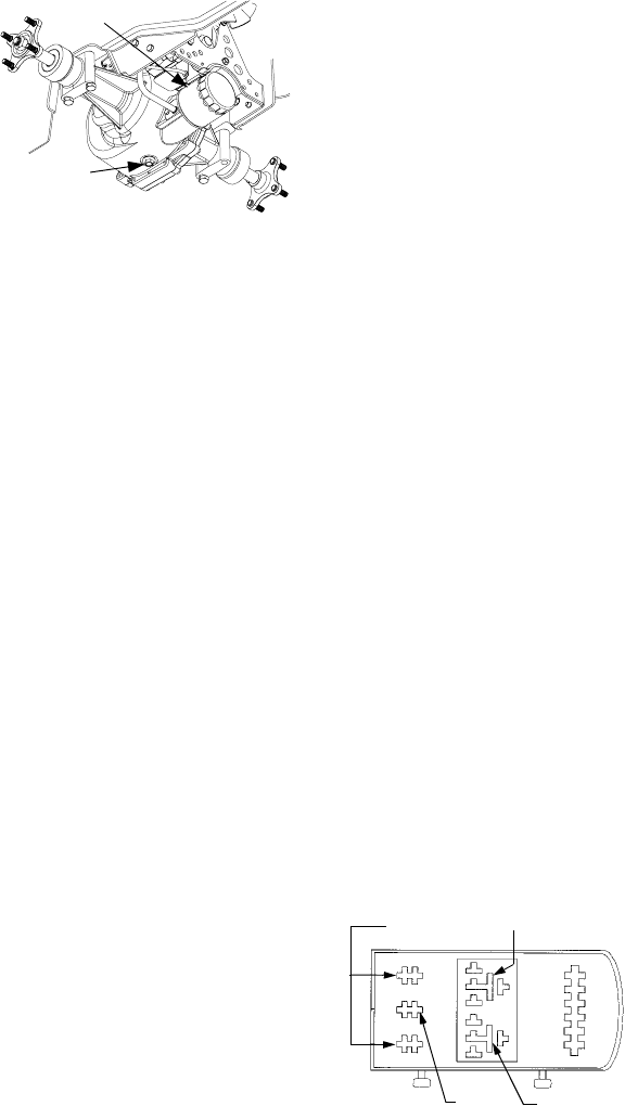
Electrical Box
The electrical box contains the relay
and fuses. See Figure 23 for the
electrical box layout. The electrical box
is located under the upper bulkhead in
front of the dash panel. To access the
electrical box:
•Raise the hood of the tractor
•Locate the locking tabs on the left
and right side of the upper
bulkhead.
•Pull up on the tabs and lift the upper
bulkhead from the tractor.
•Lift the locking tab and remove the
cover from the electrical box.
Figure 23
Oil Filter
Transmission
Drain Plug
Relay
Open
25 Amp
Fuses
Open
26
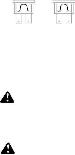
Fuse
Fuses are installed to protect the trac-
tor’s electrical system from damage
caused by excessive amperage.
Always use the same capacity fuse for
replacement. Refer to the Specifica-
tions Chart. If the electrical system
does not function, check the fuses.
To replace a fuse, note the position of
the fuse and pull the old fuse from the
electical box.
Compare the suspect fuse with Figure
24 to determine if is good or bad.
Figure 24
Install the new fuse in the position
from which the old fuse was removed.
Off-Season Storage
If the machine is to be inoperative for
a period longer than 30 days, the fol-
lowing procedures are recommended:
WARNING: Never store the
tractor with fuel in the tank
indoors or in poorly venti-
lated enclosures, where fuel
fumes may reach an open
flame, spark or pilot light as
on a furnace, water heater,
clothes dryer, etc.
WARNING: Fuel left in the
fuel tank deteriorates and
will cause serious starting
problems.
To prevent gum deposits from forming
inside the engine’s carburetor and
causing possible malfunction of the
engine, the fuel system must be either
completely emptied, or the gasoline
must be treated with a stabilizer to
prevent deterioration.
1. If using a fuel stabilizer:
•Read the product manufacturer’s
instructions and recommendations.
•Add to clean, fresh gasoline the
correct amount of stabizer for the
capacity of the fuel system.
•Fill the fuel tank with treated fuel
and run the engine for 2-3 min-
utes to get stabilized fuel into the
carburetor.
2. If emptying the fuel system:
•Towards end of the season,
monitor fuel consumption with the
goal of running the fuel tank to
empty.
•If a large volume of fuel is left-
over, remove the fuel cap and
siphon the the bulk of any leftover
fuel into an approved container.
•Run the engine until it starts to
falter, then use the choke to keep
the engine running until all fuel in
the carburetor has been ex-
hausted.
3. Perform the following procedures
before storing the machine.
•Remove the spark plugs and pour
one (1) ounce of engine oil
through the spark plug holes into
the cylinders. Install the spark
plugs but do not connect the plug
wires. Crank the engine two or
three revolutions to distribute the
oil.
•Clean the engine and the entire
tractor thoroughly.
•Lubricate all lubrication points.
•Prepare the battery for storage.
•Protect the tires and seat from
sunlight. Regularly check the tires
for proper inflation.
NOTE: We do not recommend the use
of a pressure washer or garden hose
to clean your unit. They may cause
damage to electrical components;
spindles; pulleys; bearings; or the
engine. The use of water will result in
shortened life and reduce
serviceability.
GOOD BAD

27
SECTION 10: ENGINE INFORMATION
KOHLER CO.
FEDERAL AND CALIFORNIA EMISSION CONTROL SYSTEMS
LIMITED WARRANTY
SMALL OFF-ROAD EQUIPMENT ENGINES
The U.S. Environmental Protection Agency (EPA),
the California Air Resources Board (CARB), and
Kohler Co. are pleased to explain the Federal and
California Emission Control Systems Warranty on
your small off-road equipment engine. For
California, engines produced in 1995 and later
must be designed, built and equipped to meet the
state’s stringent anti-smog standards. In other
states, 1997 and later model year engines must be
designed, built and equipped, to meet the U.S.
EPA regulations for small non-road engines. The
engine must be free from defects in materials and
workmanship which cause it to fail to conform with
U.S. EPA standards for the first two years of
engine use from the date of sale to the ultimate
purchaser. Kohler Co. must warrant the emission
control system on the engine for the period of time
listed above, provided there has been no abuse,
neglect or improper maintenance.
The emission control system may include parts
such as the carburetor or fuel injection system, the
ignition system, and catalytic converter. Also
included are the hoses, belts and connectors and
other emission related assemblies.
Where a warrantable condition exists, Kohler Co.
will repair the engine at no cost, including
diagnosis (if the diagnostic work is performed at an
authorized dealer), parts and labor.
MANUFACTURER’S WARRANTY
COVERAGE
Engines produced in 1995 or later are warranted
for two years in California. In other states, 1997
and later model year engines are warranted for
two years. If any emission related part on the
engine is defective, the part will be repaired or
replaced by Kohler Co. free of charge.
OWNER’S WARRANTY
RESPONSIBILITIES
(a) The engine owner is responsible for the per-
formance of the required maintenance listed
in the owner’s manual. Kohler Co. recom-
mends that you retain all receipts covering
maintenance on the engine. But Kohler Co.
cannot deny warranty solely for the lack of
receipts or for your failure to assure that all
scheduled maintenance was performed.
• Oxygen sensor (if equipped)
• Exhaust manifold (if equipped)
• Fuel metering valve (if equipped)
• Crankcase breather (if equipped)
• Gaseous fuel regulator (if equipped)
• Carburetor or fuel injection system
• Air filter, fuel filter, and spark plugs (only to first
scheduled replacement point)
(b) Be aware, however, that Kohler Co. may deny
warranty coverage if the engine or a part has
failed due to abuse, neglect, improper main-
tenance or unapproved modifications.
(c) For warranty repairs, the engine must be
presented to a Kohler Co. service center as
soon as a problem exists. Call 1-800-544-
2444, or access our web site at:
www.kohlerengines.com, for the names of
the nearest service centers. The warranty
repairs should be completed in a reasonable
amount of time, not to exceed 30 days.
If you have any questions regarding warranty
rights and responsibilities, you should contact
Kohler Co. Engine Service at 1-920-457-4441
and ask for an Engine Service representative.
COVERAGE
Kohler Co. warrants to the ultimate purchaser and
each subsequent purchaser that the engine will be
designed, built and equipped, at the same time of
sale, to meet all applicable regulations. Kohler Co.
also warrants to the initial purchaser and each
subsequent purchaser, that the engine is free
from defects in material and workmanship which
cause the engine to fail to conform with applicable
regulations for a period of two years.
Engines produced in 1995 or later are warranted
for to years in California. For 1997 and later model
years, EPA requires manufacturers to warrant
engines for two years in all other states. These
warranty periods will be begin on the date the
engine is purchased by the initial purchaser. If any
emission related part on the engine is defective,
the part will be replaced by Kohler Co. at no cost
to the owner. Kohler Co. is liable for damages to
other engine components caused by the failure of
a warranted part still under warranty.
Kohler Co. shall remedy warranty defects at any
authorized Kohler Co. engine dealer or warranty
station. Warranty repair work done at an autho-
rized dealer or warranty station shall be free of
charge to the owner if such work determines that
a warranted part is defective.
Listed below are the parts covered by the Federal
and California Emission Control Systems
Warranty. Some parts listed below may require
scheduled maintenance and are warranted up to
the first scheduled replacement point for that part.
The warranted parts are:
• Intake manifold (if equipped)
• Catalytic muffler (if equipped)
• Spark advance module (if equipped)
• Ignition module(s) with high tension lead
• Electronic control unit (if equipped)
• Fuel lines (if equipped)

28
LIMITATIONS
This Emission Control System Warranty shall not
cover any of the following:
(a) repair or replacement required because of
misuse or neglect, improper maintenance,
repairs improperly performed or replacement
not conforming to Kohler Co. specifications
that adversely affect performance and/or
durability, and alterations or modifications
not recommended or approved in writing by
Kohler Co.,
(b) replacement of parts and other services and
adjustments necessary for required mainte-
nance at and after the first scheduled
replacement point,
(c) consequential damages such as loss of time,
inconvenience, loss of use of the engine or
equipment, etc.,
(d) diagnosis and inspection fees that do not
result in eligible warranty service being per-
formed, and
(e) any add-on or modified part, or malfunction
of authorized parts due to the use of add-on
or modified parts.
MAINTENANCE AND REPAIRS
REQUIREMENTS
The owner is responsible for the proper use and
maintenance of the engine. Kohler Co. recom-
mends that all receipts and records covering the per-
formance of regular maintenance be retained in
case questions arise. If the engine is resold during
the warranty period, the maintenance records
should be transferred to each subsequent owner.
Kohler Co. reserves the right to deny warranty cover-
age if the engine has not been properly maintained;
however, Kohler Co. may not deny warranty repairs
solely because of the lack of repair maintenance or
failure to keep maintenance records.
Normal maintenance, replacement or repair of
emission control devices and systems may be per-
formed by any repair establishment or individual;
however, warranty repair must be performed by a
Kohler authorized service center. Any replace-
ment part or service that is equivalent in
performance and durability may be used in non-war-
ranty maintenance or repairs, and shall not reduce
the warranty obligations of the engine manufacturer.
Maintenance, repair or replacement of the emission control devices and
systems, which are being done at the customers expense, may be performed by
any non-road engine repair establishment or individual. Warranty repairs must
be performed by an authorized warranty outlet.
29
Cleaning The Engine
This tractor has an air-cooled engine.
Air must be able to circulate freely
around the engine through the
flywheel screen, through the cooling
shrouds and over the fins of the
cylinder head and cylinder block. Keep
these areas free of accumulated dirt
and debris or the engine will overheat;
possibly causing extensive engine
damage. Regularly clean the inside of
the side panels, dash intake screen
and grille to ensure adequate cooling.
If debris has accumulated inside the
cooling shrouds, the blower housing
and cooling shrouds should be
removed and the cooling fins cleaned.
WARNING: This machine is
designed to cool properly with
the side panels in place.
Operating without the panels
could cause premature
accumulation of dirt and
debris on the engine, resulting
in inadequate cooling.
WARNING: Keep the muffler
area clean. Before running the
engine, clean the muffler area
to remove all combustible
debris. Inspect the muffler
area often when mowing
during the Fall season.
Checking Engine Oil Level
Before each use, the oil level of the
engine crankcase should be checked
to see that it is filled to the correct
level. Close monitoring of the oil level
during the first 10 hours of operation
of the engine is especially important
and the oil level should be checked
EVERY HOUR during the first five
hours of operation.
Before checking the oil level, clean the
area around the oil level dipstick to
prevent debris from entering the
crankcase. See Figure 26. Always
keep the oil level between the “FULL”
and the “ADD” marks on the dipstick.
See Figure 25.
Figure 25
When checking the oil level, the
engine must be cold, the dipstick must
be withdrawn and wiped clean, then
inserted all the way into the tube
before being withdrawn for a true
reading.
Check the oil level only while the
engine is stopped and the tractor is
level.
Adding Engine Oil
Figure 26
WARNING: Never overfill the
engine crankcase. The
engine may overheat and/or
damage may result if the
crankcase is below the
“ADD” mark or over the
“FULL” mark on the dipstick.
For best results, fill to the
“FULL” mark on the dipstick
as opposed to adding a given
quantity of oil. Always check
the level on the dipstick
before adding more oil.
F
A
Operating
Range
Full
Add
Dipstick Oil Fill Cap
30
Refer to Figure 27 for information
regarding the proper type of oil to add
to the crankcase.
• Place the tractor on a level surface
and engage the parking brake. Stop
the tractor engine and remove the
ignition key.
• Clean the area around the oil filler
cap to prevent debris from entering
the crankcase. See Figure 26.
• Remove the oil filler cap from the
left valve cover and SLOWLY pour
in oil. Fill the crankcase until the oil
level reaches the “FULL” mark on
the dipstick. See Figure 25.
• Reinstall the oil filler cap and turn to
the right to tighten securely in the
valve cover.
WARNING: The oil filler cap
must be tightened securely
into the valve cover at all
times when the engine is
operating. Severe engine
damage could result from
failure to do so.
Changing Engine Oil
WARNING: If the tractor has
recently been operated, the
engine and surrounding
areas may be hot. Use cau-
tion not to burn yourself
when working around the
engine.
The oil filter should be changed at
every oil change interval. The filters
can be obtained through your Cub
Cadet dealer. See the Quick
Reference Chart on page 44 for the
correct part number. Refer to the
MAINTENANCE CHART on page 19
and the SPECIFICATIONS TABLE on
page 36 for information regarding the
frequency of required oil changes and
the quantity of oil needed.
See the VISCOSITY CHART in Figure
27 for the proper type of oil.
Figure 27
The oil filter is located behind the left
side panel and is mounted on the
engine oil cooler. See Accessing
Engine Compartment on page 21 for
details on removing the side panels.
Run the engine for a few minutes to
warm the oil in the crankcase. Warm
oil will flow more freely and carry away
more engine impurities. Use care to
avoid burns from hot oil. While the
engine oil is warm, proceed as follows:
NOTE: A length of flexible tubing is
supplied with the tractor and should be
used to drain the engine oil.
Figure 28
• Place the tractor on a level surface
and engage the parking brake. Stop
the tractor engine and remove the
ignition key.
• Clean around the base of the oil
filter, the oil filler cap, and the
dipstick tube to prevent debris from
entering the crankcase. See Figure
26 and Figure 28.
• Unseat the plastic dust cap from the
engine oil drain valve. To prevent
loss of the cap, do not remove the
cap’s retaining ring from the drain
valve. Remove the dipstick.
Above +32° F SAE 10W30
SAE 10W40
Below +32° F SAE 5W20
SAE 5W30
Oil Filter
Oil Drain Valve
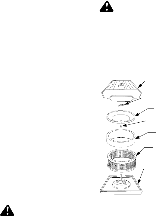
31
• Attach the flexible tubing to the
drain valve. Place an appropriate
container below the open end of the
tubing to collect the old oil.
• To open the drain valve, push it
slightly inward and turn it
counterclockwise until it stops, then
pull it outward.
• Remove the filter by turning it coun-
terclockwise using an automotive
type filter wrench to loosen.
• Allow the old oil to completely drain
from the engine crankcase into the
container below. To close the drain
valve, push it inward, turn clockwise
until it stops and then release it.
• Remove the flexible tubing from the
drain valve. Clean the tubing and
store in a safe place for future use.
• Clean the drain valve and push the
plastic dust cap onto the valve.
• Turn the replacement filter open end
up and pour new oil into the filter
through the threaded center hole.
Fill to the bottom of the threads,
then wait a minute or two to allow
the oil to be absorbed into the filter
material.
• Apply a light coating of clean oil on
the gasket of the new oil filter.
Thread the filter on by hand until the
gasket contacts the oil filter adapter,
then tighten the oil filter an
additional 2/3 to 1 turn.
• Refill the crankcase with the
appropriate quantity and type of oil.
• Check oil level and make sure that
oil filler cap, dipstick and drain valve
are in place and closed.
Sparkplugs
WARNING: To avoid possi-
ble injury, be sure the en-
gine is off and has cooled
before making any adjust-
ments or repairs.
Remove all dirt from around the spark
plug before removing.
Use a spark plug wrench to remove
the spark plugs.
Check the gap after every 100 hours
of operation.
Replace a defective plug with a new
plug. Set the spark plug gap at .030
inch. Tighten the plug to 18-22 ft-lbs.
See your authorized dealer for the
correct replacement plug.
Changing Fuel Filter
WARNING: Do not replace
fuel filter when engine is hot.
The engine is equipped with an in-line
fuel filter. Visually inspect the filter
periodically for a build-up of residue
inside the filter body, and for a dirty
element which can be indicated by
discoloration. Replace the fuel filter
when dirty.
Changing Air Cleaner
Figure 29
Check the air cleaner daily or before
starting the engine. Check for loose or
damaged components and check the
condition of the filter element. Remove
any buildup of dirt and debris in the air
cleaner housing.
See Figure 29 for assembly of the Air
cleaner elements.
Air Cleaner
Cover w/Knob
Element Cover
Element Cover
Foam
Paper Element
Air Cleaner Base
Precleaner
Rubber Seal
Wing Nut

32
WARNING: Operating the
engine with loose or dam-
aged air cleaner components
will allow unfiltered air into
the carburetor, causing ex-
tensive wear and eventual
failure of the engine.
Servicing The Precleaner
Wash and re-oil the foam precleaner
more often under extremely dusty or
dirty conditions. See Figure 29.
• Loosen the aircleaner cover knob
and remove the cover.
• Remove the foam precleaner by
sliding it up off the paper element.
• Wash the precleaner in warm water
with detergent. Rinse the precleaner
thoroughly until all traces of the
detergent are eliminated. Squeeze
out (do not wring) excess water in a
dry cloth. Allow the precleaner to air
dry.
• Saturate the foam precleaner with
new engine oil. Squeeze out all
excess oil in a dry cloth.
• Reinstall the foam precleaner over
the paper element.
• Reinstall the air cleaner cover and
tighten the retaining knob to secure.
Servicing The Paper Element
Inspect and replace the paper element
as necessary. See Figure 29.
• Loosen the air cleaner cover knob
and remove the cover.
• Remove the foam precleaner by
sliding it up off the paper element.
• Clean the area around the element
to prevent debris from getting into
the engine when the element is
removed.
• Loosen and remove the element
cover wing nut.
• Remove the air filter element and
element cover by lifting straight up.
• Do not wash the paper element or
use pressurized air, as this will
damage the element. Replace a
dirty, bent or damaged element.
Handle new elements carefully; do
not use if the sealing surfaces are
bent or damaged.
• When servicing the air cleaner,
check the air cleaner base. Make
sure it is secured and not bent or
damaged. Check the element cover
plate for damage or improper fit.
Also check the rubber seal for
damage or deterioration. Replace all
damaged air cleaner components.
• Reinstall the paper element, foam
precleaner, cover plate and element
cover wing nut.
• Reinstall the air cleaner cover and
tighten the retaining knob to secure.
IMPORTANT: Properly maintained air
cleaner elements significantly
contribute to prolonging engine life.
Servicing Oil Cooler
Inspect and clean the oil cooler,
located next to the oil filter, after every
100 hours of operation.
Clean debris from the fins of the oil
cooler with a brush or compressed air.

33
SECTION 11: TROUBLE SHOOTING
Possible Cause Possible Remedy
Hard To Start
No fuel in fuel tank or carburetor Fill the tank with fuel. Check the fuel line,
carburetor and fuel filter.
Fuel ine or carburetor clogged Clean the fuel line and carburetor with a
commercial carburetor cleaner.
Fuel filter plugged Replace
Water in fuel Drain the fuel tank and carburetor. Use new
fuel and dry the sparks plugs.
Choked improperly. Flooded engine Follow the starting instructions.
Defective ignition or loose wiring Check the wiring, spark plugs or fuse.
Defective battery Check and service. Refer to “BATTERY.”
Spark plug dirty or improperly gapped Clean, adjust the gap to .030-inch or replace
the plug.
Engine Operates Irregularly or Knocks
Engine incorrectly timed See your authorized dealer.
Spark plug dirty; wrong gap or wrong type Clean, reset the gap or replace
Poor or weak spark Check the spark plugs and wiring.
Carburetor setting incorrect See your authorized dealer.
Poor grade fuel or water in fuel Drain and use a good grade of clean fuel.
Engine overheating Refer to “MAINTENANCE.”
Engine valves at fault See your authorized dealer.
Engine smokes See your authorized dealer.
Oil level rises due to fuel in the crankcase See your authorized dealer.
Air filter becomes oil and fuel soaked See your authorized dealer.
Engine leaks oil See your authorized dealer.
Misfiring See your authorized dealer.
Other engine problems See your authorized dealer.
Excessive oil in air cleaner Be sure that oil dipstick is fully seated, oil fill
cap is tight, and all excess oil is squeezed out
of the pre-cleaner.
PTO Clutch Will Not Engage
Reverse pedal is partially depressed Depress brake pedal.
Vacuum actuator not energized Check PTO switch and connections, check
for worn or broken wiring.
Vacuum leak Check vacuum lines.
Lack of Power
Air cleaner clogged Service the air cleaner element. Refer to
“MAINTENANCE.”
Engine overload Reduce the load.
Engine overheated Make sure the air intake screen, shrouding,
engine fins, side panels, dash intake screen
and grille are free of accumulated dirt and
debris. Refer to “MAINTENANCE.”

34
Fuel tank air vent clogged Remove obstruction from the vent in the fuel
tank cap.
Air leakage between carburetor and engine Remove air cleaner. Tighten the carburetor
and manifold mounting hardware. Replace
any damaged parts as indicated in “MAIN-
TENANCE.”
Incorrect timing or faulty ignition See your authorized dealer.
Brake dragging Adjust the brakes. Refer to “ADJUST-
MENTS.”
Insufficient cooling air — dirt or debris clog-
ging the: air intake screen • shrouds • cool-
ing fins • side panels • dash intake screen •
or grille
Keep the air intake area, side panels, grille,
dash intake screen and cooling fins clean.
Refer to “MAINTENANCE.”
Oil level incorrect Engine oil level must not be over the “FULL”
mark or below the “ADD” mark on dipstick.
Refer to “MAINTENANCE.”
Possible Cause Possible Remedy

35
SECTION 12: OPTIONAL EQUIPMENT
When you purchased your tractor, you probably had it completely equipped for
your particular needs at that time. However, later you may wish to obtain
optional equipment or accessories. These items and other allied equipment can
be purchased from, and installed by, your authorized Cub Cadet dealer.
This tractor can be used for many different types of work, and because it is
called on to operate under many different conditions, a variety or equipment is
available to adapt it to the requirements of the user. Refer to the optional
equipment chart below for a list of products available at the time of printing.
(1) Requires front hitch system 190-343-100.
(2) Requires front hitch system 190-343-100. Can use optional Mechanical
Angling Kit 190-171-100 or Hydraulic Angling Kit 190-288-100.
(3) Requires 3 point hitch 190-207-100.
Description Model Number
Mechanical Angling Kit
(1)
190-171-100
Hydraulic Angling Kit
(1)
190-288-100
44" Mower Deck 190-209-100
48" Mower Deck 190-289-100
54" Mower Deck 190-290-100
54" Mower Deck 190-295-100
60: Mower Deck 190-291-100
Front Hitch System 190-343-100
Grass Collection System 190-345-100
Grass Collection System 190-217A-100
Grass Collection System (44" Deck Only) 190-212-100
Grass Collection System (190-295 54" Deck Only) 190-367-100
54 Inch Blade
(2)
190-352-100
Snow Thrower
(1)
190-353-100
3 Point Hitch 190-207-100
Hydraulic Tiller
(3)
190-004-100

36
SECTION 13: SPECIFICATIONS
Engine
Manufacturer . . . . . . . . . . . . . . . . . . . . . . . . . . . . . . . . . . . . . . . . . Kohler
Horsepower . . . . . . . . . . . . . . . . . . . . . . . . . . . . . . . . . . . . . . . . . . . . . 25
Cylinders . . . . . . . . . . . . . . . . . . . . . . . . . . . . . . . . . . . . . . 2 (Command)
Cooling . . . . . . . . . . . . . . . . . . . . . . . . . . . . . . . . . . . . . . . . . . . . . . . . Air
Fast Idle Speed . . . . . . . . . . . . . . . . . . . . . . . . . . . . . . . . . . . . . . . . 3600
Slow Idle Speed . . . . . . . . . . . . . . . . . . . . . . . . . . . . . . . . . . . . . . . 1200
Displacement (cubic inches) . . . . . . . . . . . . . . . . . . . . . . . . . . . . . . . 44.0
Compression Ratio . . . . . . . . . . . . . . . . . . . . . . . . . . . . . . . . . . . . . 9.0:1
Spark Plug . . . . . . . . . . . . . . . . . . . . . RC12YC (Champion or equivalent)
Oil Filter . . . . . . . . . . . . . . . . . . . . . . . . . . . . . . . . . . . . . . . . . . . .Cartridge
Crank Case Capacity . . . . . . . . . . . . . . . . . . . . . . . . . . . . . . . . . . . 64 oz.
Electrical System
Charging System . . . . . . . . . . . . . . . . . . . . . . . . . . . . Flywheel-Alternator
Capacity . . . . . . . . . . . . . . . . . . . . . . . . . . . . . . . . . . . 15 Amp Regulated
Battery Type . . . . . . . . . . . . . . . . . . . . . . . . . . . . . . . . . . . . . . Lead Acid
Battery Cold Cranking Amps at 0° F . . . . . . . . . . . . . . . . . . . . . . . . . 435
Ignition . . . . . . . . . . . . . . . . . . . . . . . . . . . . . . . . . . . . . . . . . . . . . . Battery
Fuses (auto type) . . . . . . . . . . . . . . . . . . . . . . . . . . . . . . . . . . . . 25 amp
Battery Voltage . . . . . . . . . . . . . . . . . . . . . . . . . . . . . . . . . . . . . . 12 Volts
Fuel System
Fuel Tank Capacity (gallons) . . . . . . . . . . . . . . . . . . . . . . . . . . . . . . . 4.5
Type of Fuel . . . . . . . . . . . . . . . . . . . . . . . . . . . . . . . . . . . . . . . Unleaded
Fuel Filter . . . . . . . . . . . . . . . . . . . . . . . . . . . . . . . . . . . . . . . . . . . . In-line
Drive Train
Transmission . . . . . . . . . . . . . . . . . . . . . . . . . . . . . . . . . . . . . Hydrostatic
Transmission Oil . . . . . . . . . . . . . . . Cub Cadet Drive System Fluid Plus
Transmission Oil Capacity . . . . . . . . . . . . . . . . . . . . . . . . . . . . . 5.5 Qts.
Tires
Front (inches) . . . . . . . . . . . . . . . . . . . . . . . . . . . . . . . . . . . . 16 x 7.5 - 8
Rear (inches) . . . . . . . . . . . . . . . . . . . . . . . . . . . . . . . . . . . . 24 x 10.5 - 12
Dimensions and Weight
Wheelbase . . . . . . . . . . . . . . . . . . . . . . . . . . . . . . . . . . . . . . . . . . 49.5 in.
Overall Length . . . . . . . . . . . . . . . . . . . . . . . . . . . . . . . . . . . . . . . 72.25 in.
Overall Width (w/o Attachments) . . . . . . . . . . . . . . . . . . . . . . . . . . . 42 in.
Height . . . . . . . . . . . . . . . . . . . . . . . . . . . . . . . . . . . . . . . . . . . . . . 43.6 in.
Weight (w/o Mower Deck) . . . . . . . . . . . . . . . . . . . . . . . Approx. 803 lbs.
Turning Radius . . . . . . . . . . . . . . . . . . . . . . . . . . . . . . . . . . . . . . . . 27 in.
Ground Clearance . . . . . . . . . . . . . . . . . . . . . . . . . . . . . . . . . . . . . . . 6 in.
Brakes
Type . . . . . . . . . . . . . . . . . . . . . . . . . . . . . . . . . . . . . . . . . . External Disk
Parking . . . . . . . . . . . . . . . . . . . . . . . . . . . Foot Actuated - Hand Locked
PTO Clutch
Type . . . . . . . . . . . . . . . . . . . . . . . . . . . . . . . . . . . . . . . . . .E-Vac System
Attachment Lift System
Type . . . . . . . . . . . . . . . . . . . . . . . . . . . . . . . . . . . . . . . . . . . . . Hydraulic
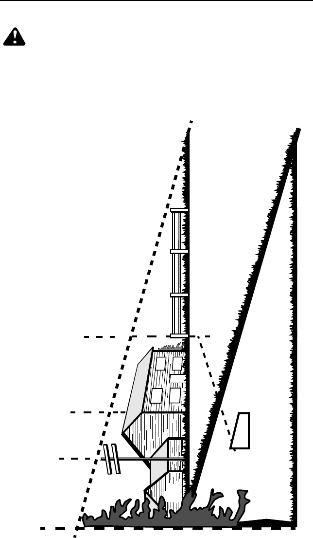
37
SECTION 14: SLOPE GAUGE
WARNING: Do not mow on inclines with a slope in excess of 15
degrees (a rise of approximately 2-1/2 feet every 10 feet). A riding
mower could overturn and cause serious injury. If operating a walk-
behind mower on such a slope, it is extremely difficult to maintain
your footing and you could slip, resulting in serious injury.
• Operate RIDING mowers up and down slopes, never across the face of slopes.
• Operate WALK-BEHIND mowers across the face of slopes, never up and down
slopes.
38

39
CUB CADET LLC
MANUFACTURER’S ONE YEAR LIMITED WARRANTY
(COMMERCIAL USE)
The limited warranty set forth below is given by CUB CADET LLC (“CUB CADET”)
with respect to new merchandise purchased and used in the United States, its
possessions and territories.
CUB CADET warrants this product against defects in material and workmanship
for a period of one (1) year for commercial users, commencing on the date of
original purchase and will, at its option, repair or replace, free of charge, any part
found to be defective in material or workmanship. This limited warranty shall only
apply if this product has been operated and maintained in accordance with the
Operator’s Manual furnished with the product, and has not been subject to
misuse, abuse, neglect, accident, improper maintenance, alteration, vandalism,
theft, fire, water or damage because of other peril or natural disaster.
Batteries and belts are subject to separate terms as follows:
a. Batteries have a one-year prorated limited warranty with 100%
replacement during the first three months. After three months, the
battery replacement credit is based on the months remaining in the
twelve (12) month period dating back to the original date of sale. Any
replacement battery will be warranted only for the remainder of the
original warranty period.
b. All belts are covered by a one (1) year limited warranty against defects
in material and workmanship.
HOW TO OBTAIN SERVICE: Warranty service is available, WITH PROOF OF
PURCHASE, THROUGH YOUR LOCAL AUTHORIZED CUB CADET DEALER.
To locate the dealer in your area, please check for a listing in the Yellow Pages or
contact CUB CADET by calling 1-877-282-8684 or writing to P.O. Box 361131,
Cleveland, Ohio 44136-0019. You may also log on to our Web site at
www.cubcadet.com.
This limited warranty does not provide coverage in the following cases:
a. Routine maintenance items such as lubricants, filters, blade sharpening
and tune-ups, or adjustments such as brake adjustments, clutch adjust-
ments or deck adjustments; and normal deterioration of the exterior fin-
ish due to use or exposure.
b. Normal wear parts or components, including blades, blade adapters,
grass bags, rider deck wheels, seats, snow thrower skid shoes, shave
plates and tires.
c. CUB CADET does not extend any warranty for products sold or exported
outside of the United States of America, its possessions and territories,
except those sold through CUB CADET’S authorized channels of export
distribution.
No implied warranty, including any implied warranty of merchantability or
fitness for a particular purpose, applies after the applicable period of
express written warranty above. No other express warranty or guaranty,
whether written or oral, except as mentioned above, given by any person or
entity, including the dealer, with respect to any product shall bind CUB
CADET. During the period of the Warranty, the exclusive remedy is repair
or replacement of the product as set forth above. (Some states do not allow
limitations on how long an implied warranty lasts, so the above limitation may not
apply to you.)
40
The provisions as set forth in this Warranty provide the sole and exclusive
remedy arising from the sale. CUB CADET shall not be liable for incidental
or consequential loss or damages including, without limitation, to any claim
for loss of profits, loss of savings or revenue, loss of the use of the
equipment or any associated equipment, facilities or service, downtime, the
claims or costs of third parties including customers, and injury to property,
and further including expenses incurred for substitute or replacement lawn
care services, for transportation or for related expenses, or for rental
expenses to temporarily replace a warranted product. (Some states do not
allow the exclusion or limitation of incidental or consequential damages, so the
above exclusion may not apply to you.)
In no event shall recovery of any kind be greater than the amount of the purchase
price of the product sold. Alteration of the safety features of the product shall void
this Warranty. You assume the risk and liability for loss, damage, or injury to you
and your property and/or to others and their property arising out of the use or
misuse or inability to use the product.
This limited warranty shall not extend to anyone other than the original purchaser
or original lessee.
How State Law Relates to this Warranty: This limited warranty gives you
specific legal rights, and you may also have other rights which vary from state to
state.

41
CUB CADET LLC
MANUFACTURER’S LIMITED WARRANTY
(RESIDENTIAL USE)
The limited warranty set forth below is given by CUB CADET LLC (“CUB CADET”)
with respect to new merchandise purchased and used in the United States, its
possessions and territories.
CUB CADET warrants this product against defects in material and workmanship
for a period of two (2) years for residential users, (one (1) year for commercial
users), commencing on the date of original purchase and will, at its option, repair
or replace, free of charge, any part found to be defective in material or
workmanship. This limited warranty shall only apply if this product has been
operated and maintained in accordance with the Operator’s Manual furnished with
the product, and has not been subject to misuse, abuse, neglect, accident,
improper maintenance, alteration, vandalism, theft, fire, water or damage
because of other peril or natural disaster.
Batteries and belts are subject to separate terms as follows:
a. Batteries have a one-year prorated limited warranty with 100%
replacement during the first three months. After three months, the
battery replacement credit is based on the months remaining in the
twelve (12) month period dating back to the original date of sale. Any
replacement battery will be warranted only for the remainder of the
original warranty period.
b. All belts are covered by a one (1) year limited warranty against defects
in material and workmanship.
3 Year Limited Warranty - PTO Clutch
CUB CADET warrants the power take off (“PTO”) clutch and mounting hardware
against defects in material and workmanship for a period of three (3) years for
Series 2000 products manufactured after August 1, 1997 for residential users,
commencing on the date of original purchase or lease and CUB CADET will, at its
option, repair or replace, free of charge, any PTO clutch or mounting hardware
found to be defective in material or workmanship provided this product has been
operated and maintained as set forth above.
5 Year/500 Hour Limited Warranty
CUB CADET warrants the frame, front cast iron pivot axle and drive shaft on
Series 2000 and 3000 models against defects in material and workmanship for a
period of five (5) years or 500 hours, whichever occurs first, for residential users,
commencing on the date of original purchase or lease and CUB CADET will, at its
option, repair or replace, free of charge, any part found to be defective in material
or workmanship provided this product has been operated and maintained as set
forth above. In addition to any other reason set forth herein, CUB CADET may
deny warranty coverage if the hour meter, or any part thereof, is altered, modified,
disconnected or otherwise tampered with.
HOW TO OBTAIN SERVICE: Warranty service is available, WITH PROOF OF
PURCHASE, THROUGH YOUR LOCAL AUTHORIZED CUB CADET DEALER.
To locate the dealer in your area, please check for a listing in the Yellow Pages or
contact CUB CADET by calling 1-877-282-8684 or writing to P.O. Box 361131,
Cleveland, Ohio 44136-0019. You may also log on to our Web site at
www.cubcadet.com.

42
This limited warranty does not provide coverage in the following cases:
a. Routine maintenance items such as lubricants, filters, blade sharpening
and tune-ups, or adjustments such as brake adjustments, clutch adjust-
ments or deck adjustments; and normal deterioration of the exterior fin-
ish due to use or exposure.
b. CUB CADET does not extend any warranty for products sold or exported
outside of the United States of America, its possessions and territories,
except those sold through CUB CADET’S authorized channels of export
distribution.
c. Normal wear parts or components, including blades, blade adapters,
grass bags, rider deck wheels, seats, snow thrower skid shoes, rubber
auger spirals, shave plates and tires.
No implied warranty, including any implied warranty of merchantability or
fitness for a particular purpose, applies after the applicable period of
express written warranty above as to the parts as identified. No other
express warranty or guaranty, whether written or oral, except as mentioned
above, given by any person or entity, including the dealer, with respect to
any product shall bind CUB CADET. During the period of the Warranty, the
exclusive remedy is repair or replacement of the product as set forth above.
(Some states do not allow limitations on how long an implied warranty lasts, so
the above limitation may not apply to you.)
The provisions as set forth in this Warranty provide the sole and exclusive
remedy arising from the sales. CUB CADET shall not be liable for incidental
or consequential loss or damages including, without limitation, expenses
incurred for substitute or replacement lawn care services, for transportation
or for related expenses, or for rental expenses to temporarily replace a
warranted product. (Some states do not allow the exclusion or limitation of
incidental or consequential damages, so the above exclusion or limitation may not
apply to you.)
In no event shall recovery of any kind be greater than the amount of the purchase
price of the product sold. Alteration of the safety features of the product shall void
this Warranty. You assume the risk and liability for loss, damage, or injury to you
and your property and/or to others and their property arising out of the use or
misuse or inability to use the product.
This limited warranty shall not extend to anyone other than the original purchaser
or original lessee.
How State Law Relates to this Warranty: This limited warranty gives you
specific legal rights, and you may also have other rights which vary from state to
state.
43
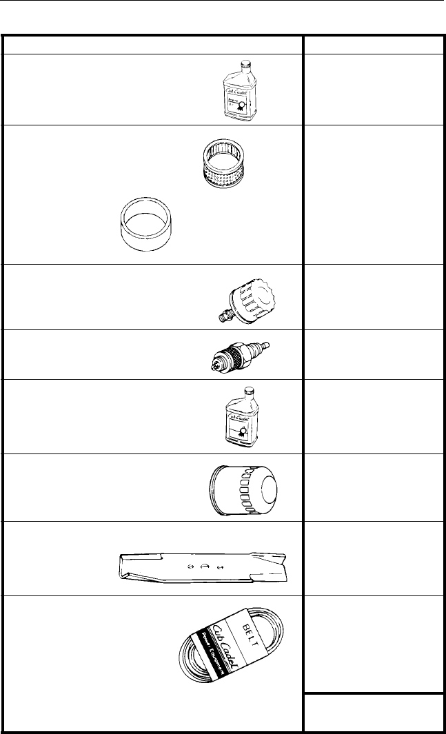
SECTION 15: QUICK REFERENCE PARTS
Description Part Number
Engine Oil
737-3030A (10W30)
737-3049 (5W30)
Air Filter
KH-47-083-03
KH-24-083-02
Engine Oil Filter
KH-12-050-08
Spark Plug
759-3336
Transmission Oil Cub Cadet Drive
System Fluid Plus
737-3120 - Quart
737-3121 - Gallon
Transmission Oil Filter
923-3014
Mower Deck
Blades 44” Deck -759-3939 (3)
48” Deck -759-3826 (3)
54” Deck -759-3820 (3)
60” Deck -759-3809 (3)
Mower Deck Belts
PTO Belt (set of 2)
44” Deck - 954-3098
48” Deck - 954-3053
54” Deck - 954-0197
60” Deck - 954-3093
954-3084
CARTRIDGE
FOAM
PRE-CLEANER
