Cub Cadet 7530 Operators Manual 7532 Pg A 81
7530 to the manual c879e7a1-b4e7-d114-cd37-da850460f18b
2015-01-05
: Cub-Cadet Cub-Cadet-7530-Operators-Manual-163779 cub-cadet-7530-operators-manual-163779 cub-cadet pdf
Open the PDF directly: View PDF ![]() .
.
Page Count: 126 [warning: Documents this large are best viewed by clicking the View PDF Link!]
IMPORTANT:
READ SAFETY RULES AND INSTRUCTIONS CAREFULLY
CUB CADET LLC P.O. BOX 361131 CLEVELAND, OHIO 44136-0019 [www.cubcadet.com]
OPERATOR’S MANUAL
COMPACT TRACTOR
Model Numbers
SERIES 7000
7530
7532
PRINTED IN U.S.A. FORM NO. 769-01060
(1/04)

A
Emission Related System Defect Warranty
Manufacturer Statement
Manufacturer Statem
Mitsubishi Heavy Industries, ltd. (MHI) will give a warranty condition, required by the
U.S. Environmental Protection Agency(EPA) and the California Air R esource
Board(CA RB) to Original Equipment Manufacturers (OEMs) for small off-road engines
purchased in 1997 and later which are used in U.S.A.
It is the OEMs responsibility to give the following warranty to the end-users for small
off-road engines purchased in 1997 and later which are used in U.S.A.
The manufacturer of MHI small off-road engines has authorized equipment
manufacturers to be th e direct contact for all warranty and service related questions
and/or repairs. All inquiries should be directed to equipment manufacturers only.
Em issio
issio
n Co
Co
ntrol Warranty Statement
ntr
Applicable only to engines purchased in U.S.A. in 1997 and thereafter which are used
in U.S.A. .
EPA emission control defects warranty statement – Your ( Customer) defects warranty
rights and obligations:
EPA and Mitsubishi Heavy Industries, Ltd. are pleased to explain the emission control
system warranty on your 1997 and later small off-road engine. In U.S.A., new small
off-road engines must be designed, built and equipped to meet the EP A stringent
anti-smog s tandards. Mitsubishi Heavy Industries, Ltd. must warrant the emission
control system on your small off-road engine for the periods of time listed below,
pr ovided there has been no abuse, neglect or imp roper maintenance of your small
off-road engine.
Where a warrantable condition exists, the (OEMs) will repair your small off-road
engine at no cost to you i ncluding diagnosis, parts and labor .
Off-Road Diesel Engine
Emission Control System Warranty Statement
B
Manufacturer
Manufacture
r
’s Emission Control Warranty Coverage
Applicable only to engines purchased in U.S.A. in 1997 and thereafter which are used
in U.S.A.
Emission control systems warranty coverage.
The small off-road engines are warranted as to emission control parts defects for a
period, which is prescribed by US EPA CFR Part 89, subject to provisions as set forth
hereafter . If any covered part on your engine is defective, the part will be repaired by
(OEMs).
Owner ’s warran
s warra
n
ty responsibility
As the sma ll off-road engine owner , you ar e responsible for the performance of the
required maintenance listed in your owner ’s manual. (OEMs) recommends that you
retain all receipts covering maintenance on your small off-road engine. But (OEMs)
cannot deny warranty solely for the lack of re ceipts or for your failure to ensure t he
performance of all scheduled maintenance.
As the small off-road engine owner, you should be aware, howe ver, that OEMs may
deny you warranty coverage if your small off-road engine or a part has failed due to
abuse, neglect, impr oper maintenance or unapproved modifications.
You are responsible for pr esenting y our small off-road engine to an authorized service
dealer (authorized by OEMs) of small off-road engines as soon as a problem exists. The
undisputed warranty repairs should be completed in a reasonable amount of time, not
to exceed 30 days. If you have any questi on regarding your warranty rights and
responsibilities, you should contact (CUB CADET) at 1-330-273-4550. The emission
warranty is a defects warranty. Defects are jud ged on nor mal engine perf ormanc e.
The warranty is not rela ted to an in-use emission test.
Specific W
ecific W
arranty Provisions
The following are specific provisions relative to your emissions control systems
warranty coverage.
Warr
rr
anted Parts
anted Parts
Coverage under this warranty extends only t o the parts listed below (the emission
control systems parts) to the extent these parts were present on the engine purchased.
C
Fuel injection system
Fuel injection pump
Fuel inj ectors
Inlet system
Intake manifold
Exhaust system
Exhaust manifold
Turbocharger system
Turbocharger (it equipped)
Miscellaneous items used in above systems
Cylinder Head Gasket
Valve Stem Seal
Length of Coverage
Length of Coverage
MHI warrants to the initial owner and each subsequent purchaser that the warranted
parts shall be free from defects in materials and workmanship which cause the failure
of the warranted part(s) for a period, which is prescribed by US EP A CFR Part 89,
from the date the engin e is delivered to a retail purchaser.
For all engines rated under 19kW and for constant speed engines rated under 37kW
with rated speeds greater than or equal to 3,000 rp m, the warranty period is
3,000 hours or 5 years of use, whichever first occurs.
For all other engines rated at or above 19kW, the warranty period is 5,000 hours or 7
years of use, whichever f irst occurs.
No Charge
No Charge
Repair or replacement of any warranted part will be performed at no charge to the
owner, including diagnostic labor which leads to the determination that a warranted
part is defective, if the diagnostic work is perfor med at an authorized service d ealer of
small off-road engines to whom OEM s would sell engines.
Claims an
Claims an
dCoverage Exclus
Coverage Exclus
ions
Warranty claims shall be filled in accordance with the provisions of the OEMs engine
warranty policy . Warrant y coverage shall be excluded for failures of warr anted parts
D
which are not or iginal OEMs parts or because of abuse, neglect or i mpr oper
maintenance as s et forth in the OEMs engi ne warranty policy . OEMs is not liable to
cover failures of warranted parts caused by the use of add-on, non-original, or modified
parts.
Maintenance
Maintenance
Any warranted part which is not scheduled for rep lacement as required maintenance
or which is scheduled only for regular inspection to the effect of “repair or replace as
necessary” shall be warranted as to defects for the warranty period. Any warranted
part which is scheduled for replacement as required maintenance shall be warranted
as to defects only of the period of time up to t he first scheduled replacement for that
part. Any replacement part that is equivalent in performance and durability may be
used in the performance of any maintenance or repairs. The owner is responsible for
the p erfor mance of all required mai ntenance, as defined in t he MHI owner ’s manual.
Conse
Conse
quential Coverage
uential Coverage
Coverage hereunder sha ll extend to the failure of any engine components caused by
the failure of any warranted part still under warranty.
INTRODUCTION
I
INTRODUCTION
This instruction manual contains information on the operation, lubrication
and maintenance of your tractor. The information contained is
comprehensive and essential, and is designed to assist you, even if
unexperienced, in utilizing your tractor.
How well your tractor continues to give satisfactory performance depends
greatly upon the manner in which it is operated. It is, therefore, requested
that this manual be read carefully and kept ready for use so that the
operation and maintenance service will properly be carried out in order to
keep the tractor in top mechanical condition at all times.
Should any information as to your tractor be required, consult your local
dealer or distributor stating the machine and engine serial numbers of the
tractor concerned. We are sure you will be happy with your tractor.
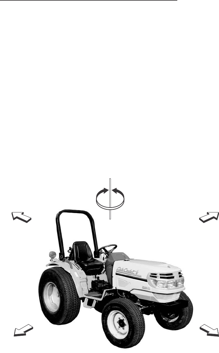
NOTE: Expressions such as LEFT, RIGHT, FRONT, or REAR used in this
manual should be understood in accordance with following rules:
FRONT means the front grill end while REAR means the lifting arm end of
the tractor. LEFT or RIGHT means the left or right hand side of the tractor
looking forward from operator’s seat.
REAR
RIGHT
LEFT
FRONT
TURN RIGHT TURN LEFT
SERIAL NUMBERS
II
SERIAL NUMBERS
Write your machine Model Name and Serial Numbers of major components
on the lines provided. If needed, give these numbers to your dealer when
you need parts or information for your machine.
1. TRACTOR MODEL NAME
2. TRACTOR SERIAL NUMBER
3. ENGINE SERIAL NUMBER
4. ROPS SERIAL NUMBER
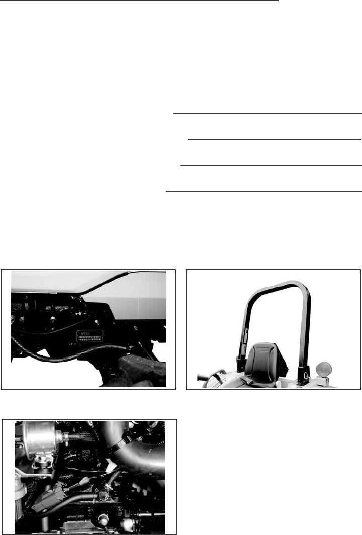
SERIAL NUMBER LOCATIONS
ROPS SERIAL NUMBER PLATETRACTOR MODEL NUMBER AND
SERIAL NUMBER PLATE
ENGINE SERIAL NUMBER

III
GENERAL TABLE OF CONTENTS
Safety/Decals 1~13
Specifications 14~18
Instruments/Controls 19~35
Operating Instructions 36~54
Field Operation 55~64
Tires/Wheels/Ballast 65~75
Lubrication/Filters/Fluids 76~103
Maintenance/Adjustments 104~109
Electrical System 110~116
Storage 117~118
SAFETY/DECALS
SAFETY PRECAUTIONS
Improper handling of the tractor could cause an accident. Prior to the
operation of the tractor, be sure to read this Manual carefully and have
a thorough understanding of all of the contents. In particular, the instructions
given in this section entitled “Safety Precautions” must be strictly followed.
REMEMBER: “SAFETY” IS ONLY A WORD UNTIL IT IS PUT INTO
PRACTICE
A. GENERAL OPERATING
SAFETY PRECAUTION
1. Observe all the safety
precautions in this manual
when operating the tractor.
2. Operate the tractor while
wearing tight clothing that
allows easy movement.
Avoid loose jackets, mufflers, ties,
scarves, or loose shirt
sleeves to prevent from being
caught by moving parts.
3. Always work when you are in
good physical condition by
taking sufficient rest to avoid
overwork.
4. Do not allow children or adults
having no knowledge of the
tractor or tractor operation,
to operate the tractor.
B. BASIC SAFETY REQUIREMENTS
FOR MAINTENANCE
Always follow these maintenance
instructions before operating
the tractor:
1. Immediately repair the head
lights and work lamps required
to conform to traffic regulations
where the tractor is operated.
2. Keep tractor steps clean to
avoid accidents due to
slippage.
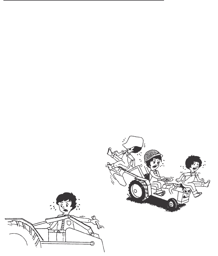
5. Never allows riders on the
tractor, linkage drawbar or
attachment while traveling
and operating them.
1
SAFETY/DECALS
3. Cover the PTO shaft with a guard
when not using.
4. Be sure to engage the brake and
lower any attachment or implement
before disassembling any part.
5. Never adjust or service the tractor
when it is in motion or while the
engine is running. Always adjust
the brake or clutch properly in
accordance with the adjusting
procedure in the instruction book.
7. Hydraulic oil or fuel escaping
under pressure can penetrate
the skin, causing serious injury.
Before disconnecting oil or fuel
lines, be sure to relieve all pressure.
Before restoring pressure after
repair, be sure all connections are
tight and all hydraulic components
are in normal condition. If injured
by leaked fluid, see a doctor
immediately for proper treatment.
2
6. Do not remove the radiator cap
while the engine is running.
Shut down the engine and wait
until it cools sufficiently. For
removal, turn the cap to the first
stop to relieve pressure.
To replace the coolant, use the
coolant recovery tank.
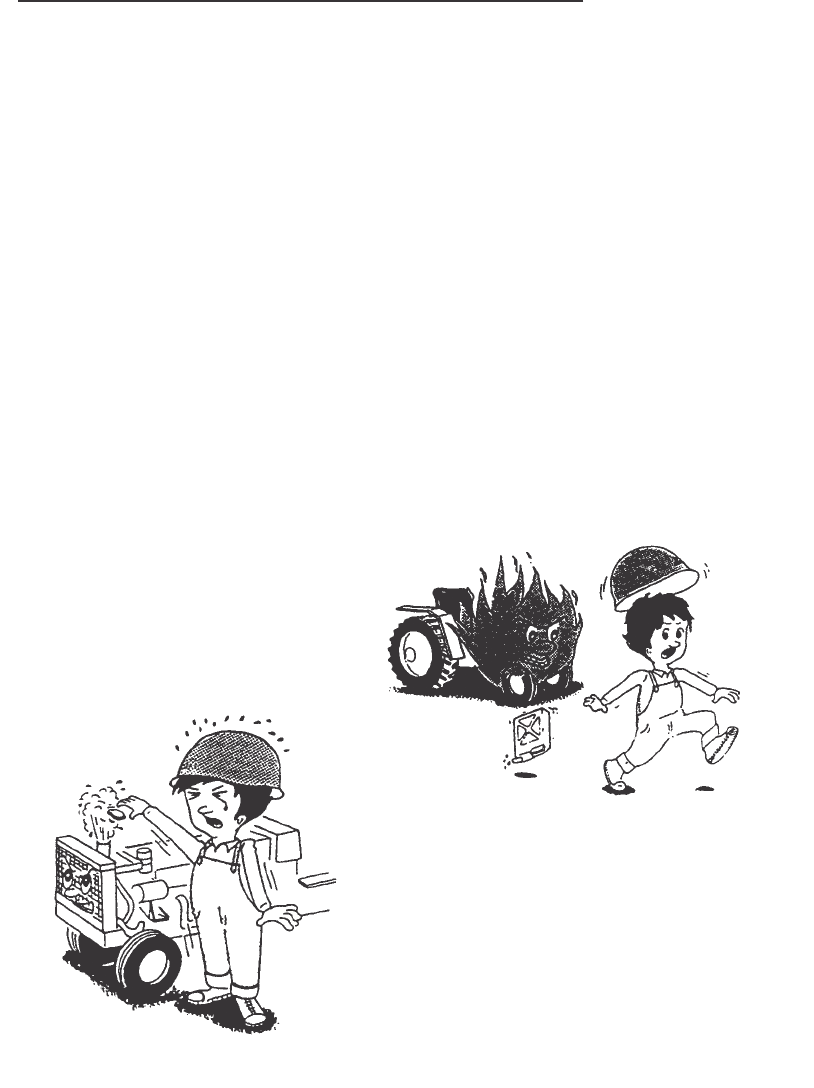
8. When refueling, be particularly
careful first to stop the engine
completely to prevent the fuel
from igniting. Never refuel in the
presence of an open flame or
while smoking.

SAFETY/DECALS
9. Before starting any work on
electrical equipment or work that
may cause you to touch the
electrical parts accidentally, first
disconnect the battery cables.
Never remove the rubber cap
cover at the positive terminal of
the battery cable end. Before
connecting the battery to the
charger, make sure that the
charger switch is in “OFF” position.
Be sure to connect the charger to
the correct terminals on the battery
(positive to positive, negative to
negative).
A great amount of hydrogen gas is
generated by the battery when it is
being charged. Take precautions
against fire: Do not have any
exposed flame in the area where
you are working.
Be sure not to cause any leakage
of the electrolyte, since it will
corrode the skin or clothing.
In case of accident as described
below, immediately seek first aid,
and see a doctor immediately for
proper treatment.
a) If the diluted sulfuric acid from
the battery has gotten into
the eyes:
Cleanse the eyes with a lot of
clean running water for more
than 15 minutes, while opening
the eyes widely.
b) If diluted sulfuric acid from the
battery has been swallowed:
Rinse the mouth with clean
water immediately and drink
a lot of raw eggs or milk. Lie
down quietly.
c) If diluted sulfuric acid has gotten
on the skin of clothing: Wash away
the diluted sulfuric acid completely
with a lot of clean running water and
neutralize with soap solution.
Then rinse with water.
d) If the diluted sulfuric acid is spilled:
Wash away with a lot of water or
neutralize with slacked lime or
bicarbonate of soda.
10. Stop the engine and make sure
the PTO shift lever is in Neutral
before performing any of the
following services, including.
a) Removal of the propeller shaft
between PTO and any attachment.
b) Adjustment of PTO drive train
and hitch.
c) Adjustment or cleaning of PTO
driven attachment.
11.The steering wheel always has
built-in play to some extent, which
is required for smooth meshing
of sector gear and pinion gear.
Always inspect the amount of
the play. Do not operate the
tractor if there is too much or
too little play in the steering.
3
SAFETY/DECALS
C. OPERATION OF THE TRACTOR
Before driving the tractor,
follow these rules:
C-1. Before starting and Driving
the Tractor
Operate the tractor only when
seated properly in operator’s seat
and keep a firm grip on the
steering wheel at all times.
Never attempt to perform any
operation of the tractor from
anywhere else, on or off the tractor.
Always wear a “hard hat” when
operating the tractor.
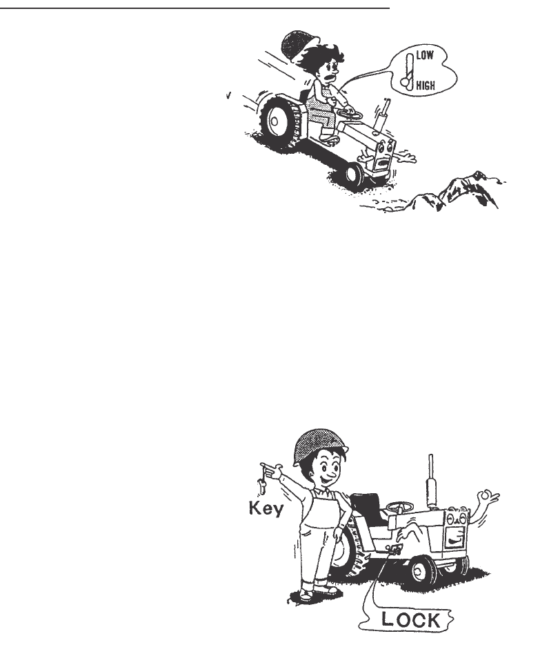
C-2. Starting and Driving the Tractor
Always operate the tractor at the
proper speeds which enable you
to keep the tractor in complete
control.
To start traveling, lower the
engine speed and release the
clutch pedal slowly.
Before leaving the tractor, stop
the engine, remove the key,
apply the parking brake and
make sure that the engine has
come to a complete stop, and
any attachment is completely
touching the ground.
4
SAFETY/DECALS
5
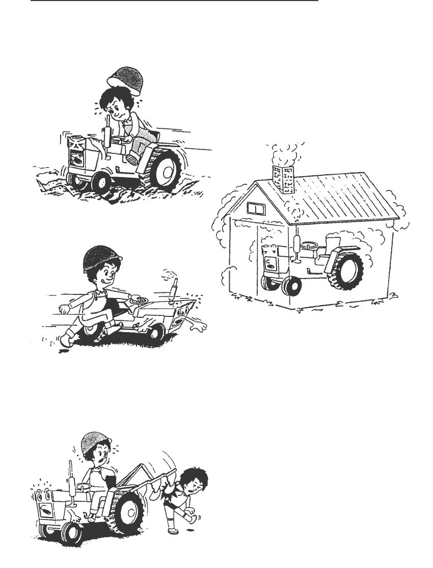
Slow down when operating the
tractor on rough ground.
Never attempt to jump on or off
a moving tractor.
When starting the tractor,
operating any attachment or
engaging the PTO make sure
that no one is in the way,
especially children.
When starting the engine in an
enclosed area or building, ensure
proper ventilation by opening the
doors and/or windows to prevent
carbon monoxide inhalation.
Mount the extension exhaust pipe
on the tractor which has a cabin.
SAFETY/DECALS
6
C-3. Traveling on Roads and Streets
For traveling on roads and streets
be sure to lock both brake pedals
together before driving to prevent
either brake from acting
independently.
Never operate the differential lock
while driving at high speed or
traveling on the road. For driving
the 4-WD tractor on the road,
be sure to place the 4-WD shift
lever in OFF position.
C-5. Towing and Operating
on Hills
For towing work on downward
slope, place the shift lever in low
speed and use engine brake.
Never try to reduce the speed with
brake only.
Towing a heavy object on a hill is
highly hazardous.
Widen the tread of the tractor and
mount the wheel weight or chassis
weight to increase the stability
and operate with extra precaution.
C-4. Steering and Turning the
Tractor
Slow down your tractor and
disengage the differential lock
before going into a turn, being
careful to prevent any attachments
mounted on the front or rear from
hitting anyone or anything
SAFETY/DECALS
7
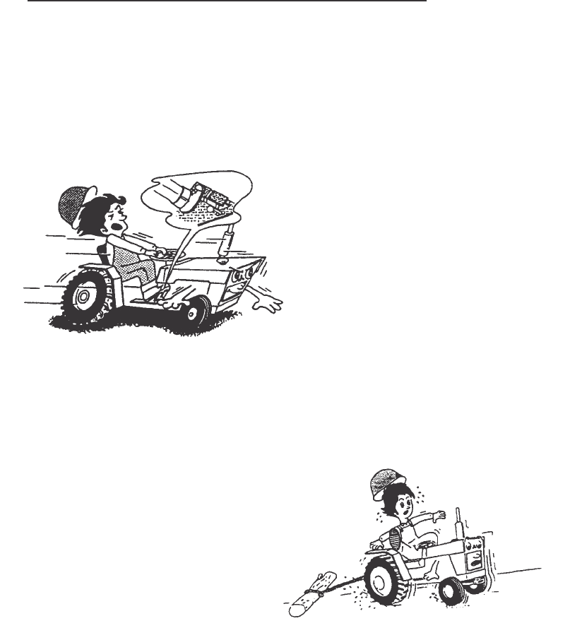
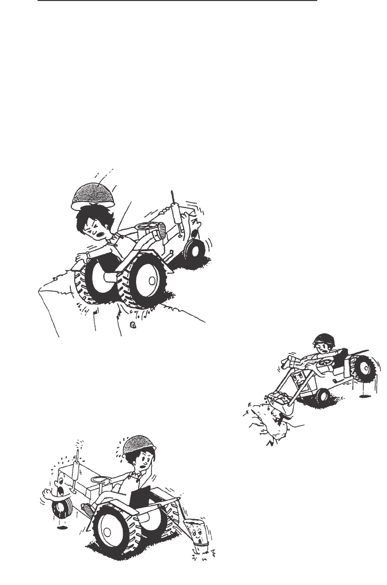
When operating the tractor on
either a steep slope or flat ground,
be sure not to suddenly steer,
brake, clutch or operate
attachments.
Do not operate the tractor at the
edge of cliff or slope. Be
particularly careful right after the
rain when soil is soft and may
give way easily.
Avoid operating the tractor on
an extreme slope that appears
hazardous, when forced to
operate on such slope, use extra
care. Driving forward out of a ditch
or mired condition or up a steep
slope could cause tractor to tip
over rearward.
Back out of such situation if possible.
If the situation does not permit you
to back out, use the front wheel
weight or the chassis weight for
balancing the tractor lengthwise.
Also in case any extra-heavy rear
mounting attachment is used, try
to obtain better balance in this
manner.
For towing, be sure to use the
drawbar only. Set the hitch point
below the center line of the rear axle.
When using a chain, never try to
move forward abruptly.
C-6. Using Attachment
To mount or operate attachment,
follow the instruction manual for
the particular attachment for safe
operation.
When using agricultural
chemicals with an attachment
on the tractor, always follow the
instructions in the manual for
the attachment as well as the
instructions provided by the
chemical manufacturer.
SAFETY/DECALS
IMPORTANT: Install new decals if the old decals are destroyed, lost,
painted over or can not be read. When parts are replaced that have decals,
make sure you install a new decal with each new part.
8
DECALS
NOTE: New decals are available from your Dealer.
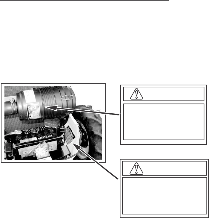
WARNING
EXPLOSION AND INJURY
CAN RESULT FROM USE
OF STARTING AIDS WITH
HOT GLOW PLUGS.
DO NOT INJECT GASOLINE
OR ETHER IN AIR INTAKE.
WARNING
BATTERIES CONTAIN ACID AND EXPLOSIVE
GAS. EXPLOSION CAN RESULT FROM
SPARKS,FLAMES, OR WRONG CABLE CON-
NECTIONS. TO CONNECT JUMPER CABLES
OR CHARGER, SEE MANUAL(S) FOR THE
CORRECT PROCEDURE. FAILURE TO
FOLLOW THE ABOVE INSTRUCTIONS CAN
CAUSE SERIOUS PERSONAL INJURY OR
DEATH
321-6714
SAFETY/DECALS
9
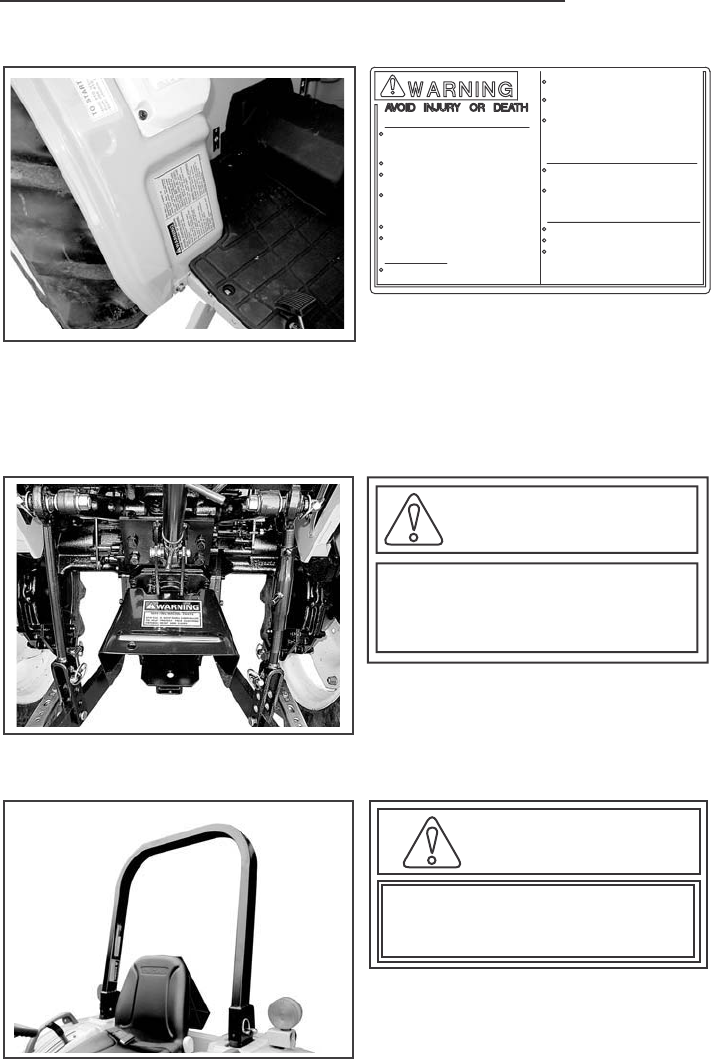
WARNING
321-3710
ROTATING MACHINE PARTS
STAY CLEAR,KEEP SHIELDS INSTALLED
TO HELP PROTECT FROM CLOTHING
ENTANGLEMENT AND INJURY.
When improperly operated,this tractor can rollover or upset.Use of ROPS
and seat belt minimize the possibility of injury or death if rollover or
upset occurs.For low clearance use only,the ROPS can be lowered.NO
protection is provided in this position and the seat belt should not be
fastened.For all other uses.secure ROPS in upright position and fasten
seat belt.
WARNING
1991603C1

SAFETY/DECALS
ROPS is a special safety unit. After an accident the ROPS must be
replaced so that you will get the same protection as a new ROPS.
ROPS, the seat, the seat belts and all the mounting, accessories and
wiring inside the operator’s protective area must be carefully checked
after a tractor accident and all parts with damage should be replaced
immediately. DO NOT TRY TO MAKE REPAIRS OR WELD ROPS.
10
Tractor Roll Over
Safety Rules
1. Do not make modification to the ROPS. Example, welding an accessory
to the ROPS, or drilling a hole in the ROPS.
2. Special fasteners are used to install the operator protective parts.
Replacement parts must be the same as given in the Parts Catalog
for your tractor.
ROPS Label
1. ROPS is equipped with a ROPS label.
2. The label contains the ROPS serial number and applicable standards.
SAFETY/DECALS
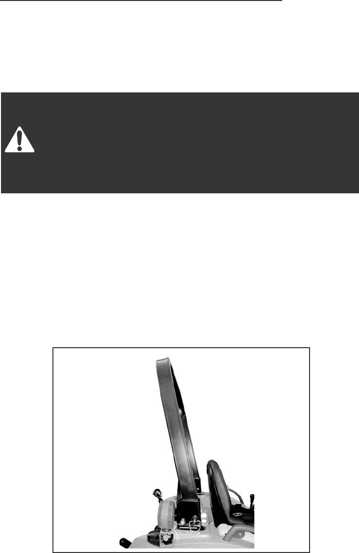
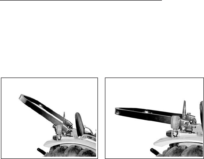
Foldable ROPS Frame
ROLL OVER PROTECTIVE STRUCTURE (ROPS)
ROPS is foldable so that the tractor can be operated in places such as
orchards where the height is restricted. See Folding the ROPS in this manual.
Normal Operating Position
For normal operation, including transport, always use the foldable ROPS
in the secured upright position with a fastened seat belt for full rollover
protection.
11
When improperly operated, this tractor can roll over or upset.
Use of the ROPS and seat belt minimize the possibility of injury
or death if rollover or upset occurs. For low clearance use only,
the ROPS can be lowered. No protection is provided in this
position and the seat belt should not be fastened. For all other
uses, secure the ROPS in the upright position and the fasten
the seat belt.
SAFETY/DECALS
Low Clearance Positions
12
For low clearance operation, such as operating in buildings, orchards or
vineyards, the ROPS can be lowered and secured in the down position.
No rollover protection is provided in the lowered positions and the seat
belt should not be fastened. When the low clearance operation is
completed, return the ROPS to the secured upright position for all other
tractor uses and transport.
IMPORTANT: When the ROPS frame is in the lowered position, make
sure there is clearance between the frame and hitch mounted equipment.
Slowly raise the hitch to maximum height to check for necessary clearance.
For drawbar attached and/or PTO driven equipment, check for clearance
including turning corners.
SAFETY/DECALS
13
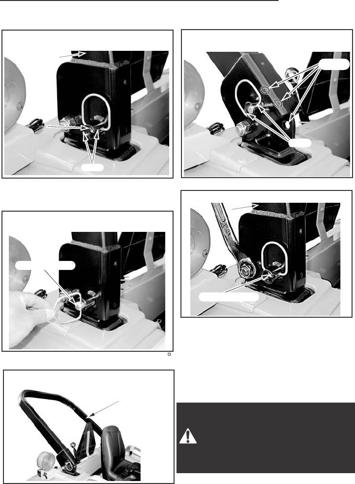
STEP 1
While holding the ROPS bar.
CAREFULLY pull the position pins.
CAREFULLY move the ROPS bar
to the desired position.
Rotate position pin and insert GUIDE
to SLIT. In this state, move ROPS bar
up and down and position pin is
installed completely ROPS bar can
set at three position.
And then Rotate position pin to (90 ).
Rollover protection is provided
only with proper assembly. Lock
pins, must be in place. Correct
parts may be obtained from your
dealer.
POSITION PIN
HOLE
SLIT
SLIT
POSITION
PIN
ROPS BAR
ROPS BAR
NORMAL
NORMAL
OPERATING
OPERATING
POSITION
(
(
ROPS BAR
NORMAL
OPERATING
POSITION
(
(
POSITION
PIN
ROPS BAR
STEP 2
STEP 3
STEP 5
Adjustment of Foldable ROPS.
If you feel less friction when the ROPS
is in the upright position, tighten the
nut untill you feel the right friction
in the movement.
STEP 4
POSITION PIN
ROPS BAR
ROPS BAR
UPRIGHT
UPRIGHT
POSITION
(
((
ROPS BAR
UPRIGHT
POSITION
(
((

SPECIFICATIONS
DIESEL ENGINE
General
Type
14
Three Cylinders, Four Stroke Cycle,
Valve in Cylinder Head, Cross
Flow Porting
Firing Order
Bore
Stroke
Piston Displacement
Compression Radio
Governor Engine Speed without Load
Rated Engine Speed
Engine Idle Speed
Maximum Horsepower (Per SAE J816b & J245)
Valve Clearance (Intake and Exhaust Cold Engine)
IMPORTANT: Valve clearance adjustment must be made when the
engine is not running and is cold.
Engine Lubrication System
Oil Pressure
Fuel Injection Pump
Injection Pump Timing
Fuel Injectors
1-3-2
84mm (3.307 inch)
90mm (3.543 inch)
1496cm (91.29 Cubic inch)
18.0 to 1
2670 to 2730 RPM
2500 RPM
1005 to 1055 RPM
30 HP at 2500 RPM
32 HP at 2500 RPM
0.25 mm (0.010 inch)
BOSCH M Plunger In Line
NIPPONDENSO ND – PFR
11Degrees Before Top Dead Center (BTDC)
Hole Type, NIPPONDENSO, ND – DLLA150P
Fuel System
3
296 to 441kPa (43 to 64 PSI) at 2500
Engine RPM with 20 W Oil at
93.3 C (200 F)
7530
7532

SPECIFICATIONS
Air Intake System
Type
15
Dry Type Air Cleaning System
with 2nd Filter
Cooling System
Type
Radiator
Thermostat
Pressure Cap
Water Temperature
Transmission
Gear Drive
Pressure System, Thermostat
Controlled Bypass, Impeller Type Pump
Corrugated and Wave Fin Type
Start to Open at Approx.82 C (180 F)
88.3kPa (12.8PSI)
Thermometer on Instrument Panel
Wet Disk Plate Type
Fully Open at 95 C (203 F)
POWER TRAIN
Operation
Parking Brakes
Type
Tractor Brakes
Mechanical
Hand Operating Lock Type
Type
Synchromesh on shuttle shift
(forward-reverse section) and main
Gear Shift of constant mesh with
two Ranges of Selective Sliding Gears
Hydrostatic Drive Hydrostatic Transmission with Three
Ranges of Selective Sliding Gears
Gear Selection
Gear Drive 8 Speeds Forward and 8 Speeds Reverse
Hydrostatic Drive 3 Speed ranges in Forward and Reverse
with Variable Speeds.
Shift Control
Gear Drive Actuated by Two Shift Levers on the LH
Fender and shuttle lever on the column.
Hydrostatic Drive Actuated by Pedal on the RH Step and
lever on the LH Fender
Oil Cooler Hydrostatic Drive only

SPECIFICATIONS
Clutch
16
Dry, Single Disc, Diaphragm Type,
215mm (8.46 Inch)
Operation Mechanical
Gear Drive
Hydrostatic Drive Dry, Single Disc, Diaphragm Type,
215mm (8.46 Inch)
Mechanical Front Drive (MFD)
Front Axle Spiral Bevel Gear Type Differential
with Bevel Gear Reductions
Differential Lock
Type
Gear Drive
Hydrostatic Drive
Controlled by Pedal on the RH Step
and Mechanically Actuated
Controlled by Pedal on the LH Step
and Mechanically Actuated
Steering
Type of Steering Hydrostatic Type
Hitch System
Type Three Point, Category
Type Control
Three Positions, Lift, Hold and lower
Type Valve
Type of Cylinder
780kg (1720lbs)
Single Acting Type
Lifting Capacity at 24”behind Lift Point (Per ASAE S349.1)
Position Control
Type, Diameter

SPECIFICATIONS
Hydraulic System
17
Front Mounted, Engine Driven,
Pressure Loading Gear Type
Hydraulic Pump Type
Capacity
Pump for Three Point Hitch
Pump for Power Steering
27.2 l/min (7.2GPM)
at 2500 Engine RPM
12.3 l/min (3.3GPM)
at 2500 Engine RPM
Maximum System Pressure 15200kPa (2204PSI)
Auxiliary Connector Front Hydraulic Block
Connector Size 9.5mm (3/8 inch)
Rear Power Takeoff (PTO)
PTO Type
Gear Drive Independent PTO
Hydrostatic Drive Live PTO
Location
Rotation
Shaft Size
Speed
At the rear of transmission
Clockwise from rear of tractor
34.9 mm (1.375 Inch) Diameter, 6Splines
540 RPM at 2376 Engine RPM
Mid Power Takeoff (PTO) OPTION
PTO Type
Gear Drive Independent PTO
Hydrostatic Drive Live PTO
Location
Rotation
Shaft Size
Speed
At the Bottom of Transmission
Clockwise from Rear of Tractor
25.4mm (1 Inch) Diameter, 15Splines
2000 RPM at 2632 Engine RPM
Drawbar
Type
Distance from Hitch Hole to the End of PTO Shaft
Maximum Vertical Load on Drawbar
Fixed Type
358mm (14.092 inch)
440Kgf (969Lb)

SPECIFICATIONS
Overall length (To end of Lower link)
18
3080 mm (121 inch)
Overall width (To end of tire)
7530
7532
Height (To top of ROPS)
Wheel base
Ground Clearance
Turning Radius (with Brake Assistance)
Weight
1360 mm (53.5 inch)
1365 mm (54 inch)
7530
7532
2110 mm (83 inch)
2140 mm (84.3 inch)
7530 1710 mm (67 inch)
7530 370 mm (15 inch)
7532 325 mm (12.8 inch)
7530
7532
2300 mm (78.8 inch)
2300 mm (78.7 inch)
7530
7532
1060 kg (2370 lbs)
1115 kg (2456 lbs)
INSTRUMENTS/CONTROLS
19
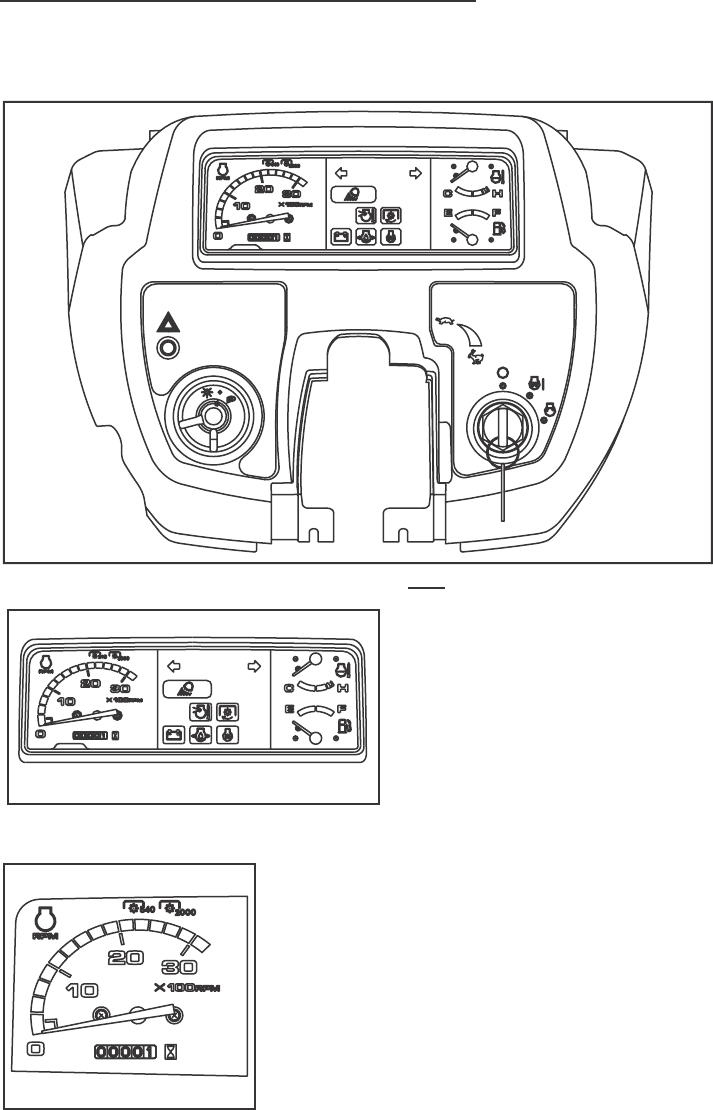
INSTRUMENTS AND INDICATORS
1. TACHOMETER AND HOURMETER The tachometer shows the
engine speed in revolutions per
minute (RPM). A symbol on the
face indicates the correct Power
Takeoff (PTO) operating speed.
The hour meter shows the hours
and tenths of hours that the engine
has operated at an average RPM.
Yellow line [A] shows the 540 rpm of the Rear
PTO speed.
Yellow line [B] shows the 2000 rpm of the MID
PTO speed.
[A] [B]
INSTRUMENTS/CONTROLS
20
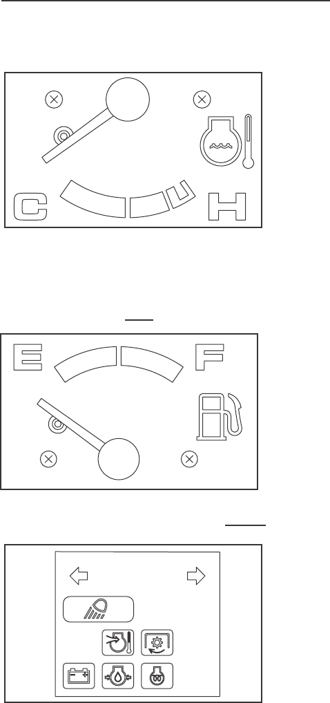
2. ENGINE COOLANT TEMPERATURE GAUGE
The gauge indicates the coolant
temperature when the starter key
switch is in ON position.
If the engine overheats, the pointer
moves right into H position area.
In this case, run the engine at
1500 RPM without load until the
pointer moves left out from H
position area. If the pointer still
stays in the H position area, stop
the engine immediately and check
for the cause.
3. FUEL GAUGE The meter shows how much fuel is in the tank.
NOTE: The pointer can be in
any position when the starter
key switch is in the OFF position.
4. TURN SIGNAL INDICATORS The LH indicator on the
TACHOMETER will operate when
the turn signal switch is turned to
the left. The RH indicator will
operate when the switch is turned
to the right. Both indicators will
operate ON and OFF when Hazard
switch is pushed down.
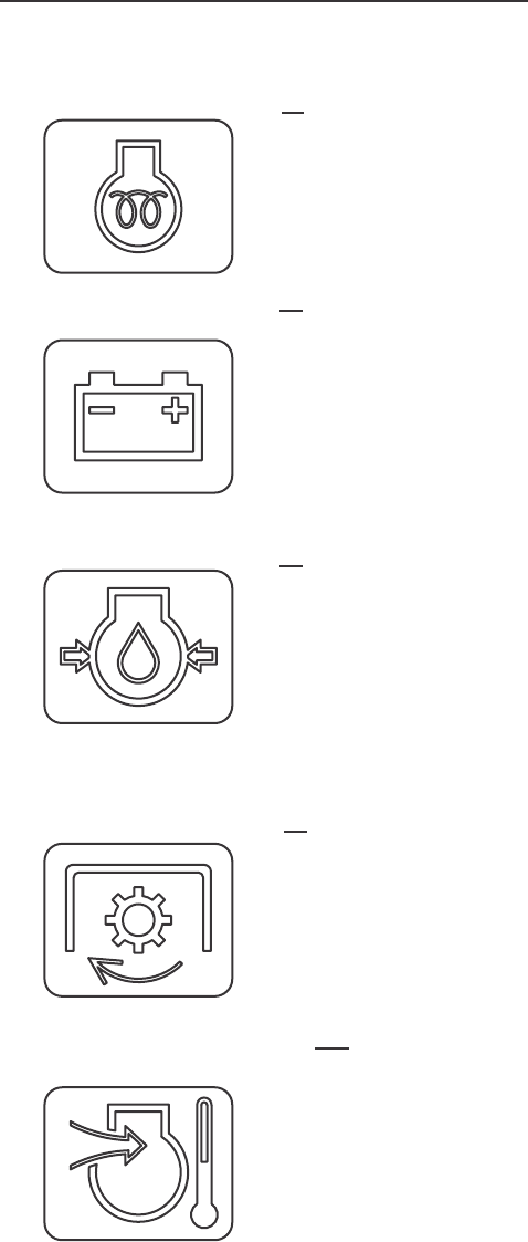
INSTRUMENTS/CONTROLS
21
5. ENGINE GLOW PLUG INDICATOR
This signal indicates the correct functioning
of the glow plug circuit. When the glow plugs have
reached the correct temperature for engine starting,
the glow plug indicator lamp will be put out.
6. CHARGE INDICATOR The charge indicator indicates the battery is
being discharged. If the lamp illuminates during
operation, stop the engine and check for the cause.
7. ENGINE OIL PRESSURE INDICATOR
The engine oil pressure indicator indicates
low engine oil pressure. If the engine oil pressure
drops below its normal pressure, the engine oil
pressure indicator will come on. Shut off the
engine immediately. Check for the cause.
8. INDEPENDENT PTO CLUTCH INDICATOR(GEAR DRIVE ONLY)
This signal indicates the INDEPENDENT
PTO CLUTCH is ON or OFF.
9. AIR HEATER INDICATOR This signal indicates AIR HEATER is ON.
INSTRUMENTS/CONTROLS
22
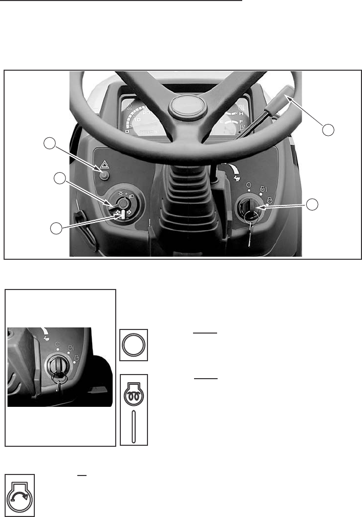
OPERATING CONTROLS
Control Switches
1. STARTER KEY SWITCH
The starter key switch can be removed with
the switch in the OFF position. Four position
switch as follows:
position
(OFF)
Engine and all lamps except
the turn signal and flasher lamps
are turned off.
Position
(HEAT)
&
(ON)
First position clockwise from
OFF. In this position (Engine not
running) energizes the glow plugs.
The charge indicator, glow plug
indicator and oil pressure indicator
will illuminate.
The fuel gauge and temperature gauge will show correct values.
position
(START)
Turn the key fully clockwise against the force of the
spring in the switch. The starter motor will turn the engine.
Release the key immediately when engine starts.
NOTE: To prevent operation by persons not authorized and the possible
discharge of the battery, remove the starter key when you leave the tractor.
IMPORTANT: Do not keep the starter key switch in the ON position for
a long period of time when the engine is not operating.
4
3
5
2
1
INSTRUMENTS/CONTROLS
23
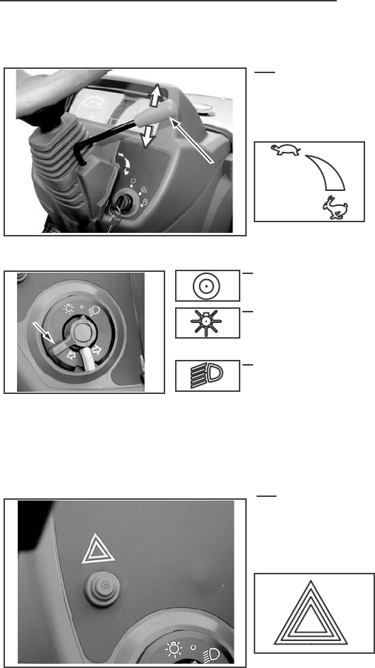
2. ENGINE SPEED CONTROL LEVER
Move the engine speed control lever
to the rear to increase engine speed.
Move the engine speed control lever
forward to decrease engine speed.
3. LAMP SWITCH Three position switch as follows:
ALL lamps are OFF. (Turn signal and
flasher lamps can be turned on.)
First position clockwise illuminates
instrument panel lamp and rear red
lamp.
Second position clockwise illuminates
headlamps, instrument panel and
rear red lamp.
Use dimmer switch to dim or brighten
the headlamps.
4. FLASHER CONTROL BUTTON
To flash the Flasher Lamps
whenever the tractor is operated or
traveling onroads.
Push the button to energize the lamps.
DECREASEDECREASE
LAMP
LAMP
SWITCH
LAMP
SWITCH
ENGINE
CONTROL
LEVER
ENGINE
CONTROL
LEVER
INCREASE
INCREASE
INCREASE
INSTRUMENTS/CONTROLS
24
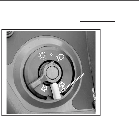
5. TURN SIGNAL SWITCH To indicate that you are going
to turn the tractor to the RIGHT, move
the turn signal switch to right . To indicate
that you are going to turn the tractor to
the LEFT, move the turn signal switch
to left . Center position is OFF.
TURN
SIGNAL
SWITCH
TURN
SIGNAL
SWITCH
INSTRUMENTS/CONTROLS
25
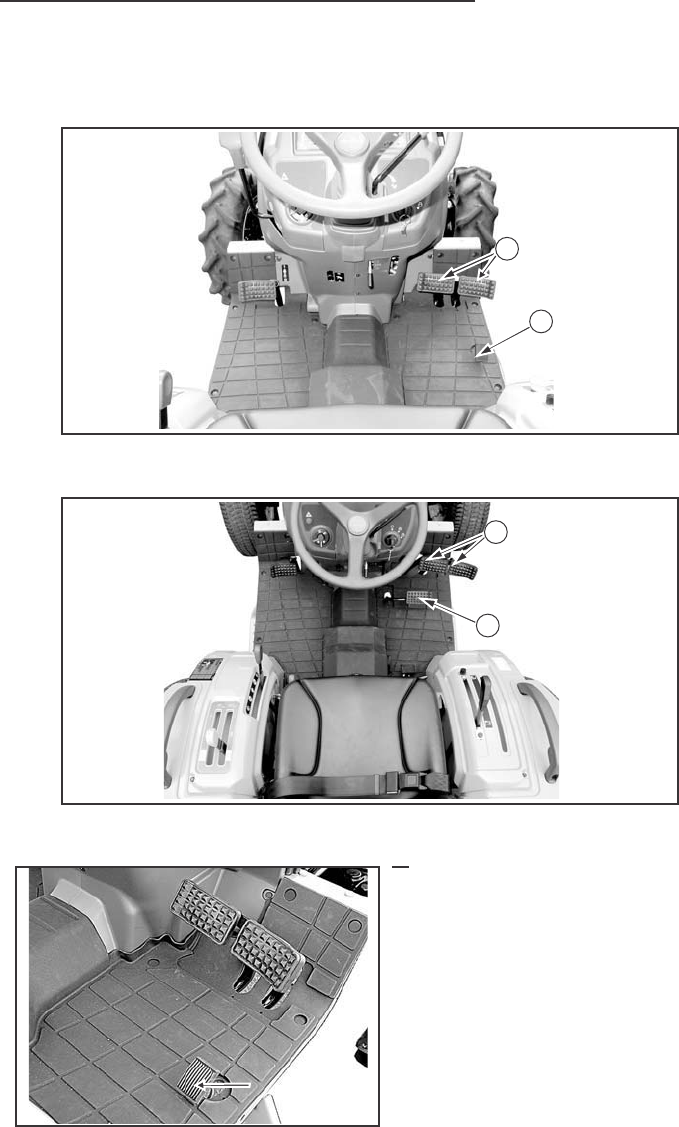
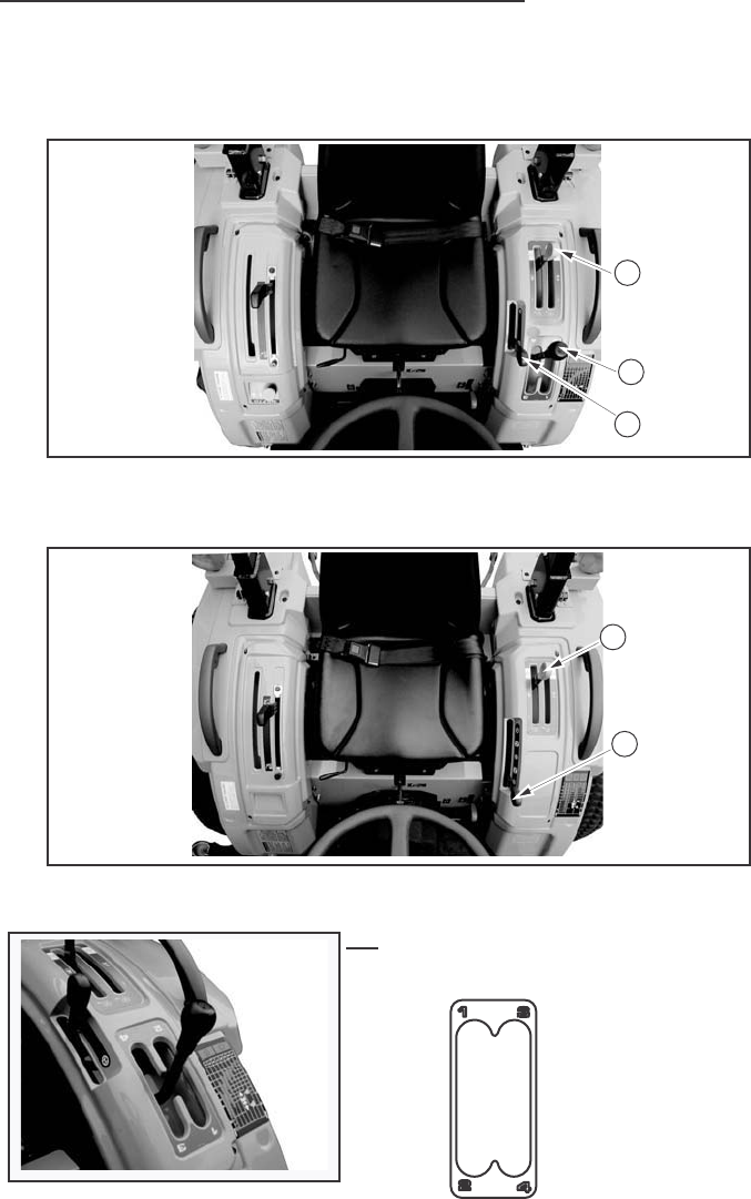
Control Levers and Pedals
(Gear Drive)
(Hydrostatic Drive)
1. ACCELERATOR PEDAL (GEAR DRIVE ONLY)
Use this pedal when operating
the tractor on the road. Push the
pedal down to increase engine
speed.
NOTE: The engine speed control
lever must be set to give the slowest
engine speed when the throttle
pedal is used.
ACCELERATOR
PEDAL
ACCELERATOR
PEDAL
3
1
2
3
INSTRUMENTS/CONTROLS
26
2. SPEED RATIO CONTROL PEDAL (HYDROSTATIC DRIVE ONLY)
The control pedal is spring loaded to
the center or neutral position. Push down
on the front of the pedal to increase
forward speed. Push down on the rear
of the pedal to increase reverse speed.
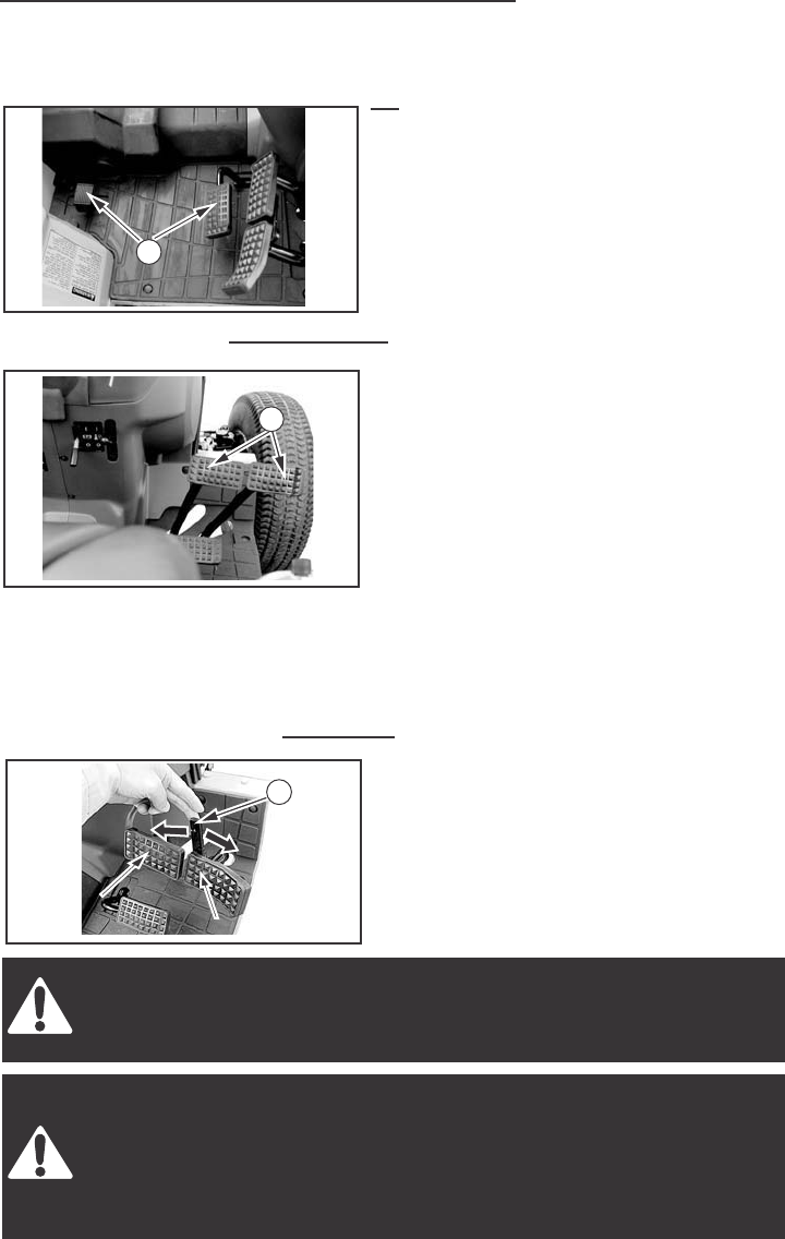
3. BRAKE PEDALS The pedals when locked together,
provides braking to both rear wheels
for stopping the tractor. When the brake
pedals are unlocked, the pedals are
used for individual braking of the rear
wheels to aid in turning the tractor
in soft soil conditions.
Push the RH brake pedal down to slow
or stop the RH rear tractor wheel, push
the LH brake pedal down to slow or slow
or step the LH rear wheel. The tractor
will turn in the direction of the wheel
that is slowed or stopped.
4. BRAKE PEDAL LOCK The brake pedal lock is located at
the brake pedal arms and is used to
lock the two brake pedals together so
that both brakes are applied.
CAUTION: Brake pedals must be locked together for road travel.
This will insure uniform brake application and maximum stopping
ability.
WARNING: Extra weight and bad traction conditions such as mud
or ice increase your stopping distance. Remember that liquid in the
tires, weight on the machine or wheels, tank filled with fertilizer,
herbicides or insecticides - all these add weight and increase
the distance you need in which to stop.
LOCKLOCK
REMOVEREMOVE
BRAKE PEDAL
BRAKE PEDAL
(LEFT SIDE)
(LEFT SIDE)
BRAKE PEDAL
(LEFT SIDE)
BRAKE PEDAL
BRAKE PEDAL
(RIGHT SIDE)
(RIGHT SIDE)
BRAKE PEDAL
(RIGHT SIDE)
2
3
4
INSTRUMENTS/CONTROLS
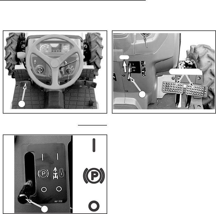
27
(GEAR Drive) (Hydrostatic Drive)
5. PARK BRAKE LEVER 1. The park brake must be on to prevent
movement of the tractor during stationary
power takeoff work or when the tractor
is parked. To engage the park brake,
lock the brake pedals together, push
down on the brake pedals and move
the park brake lever downward. Push
the brake pedal down to release the
park brake.
PARK BRAKE
PARK BRAKE
2. Before getting off the tractor,
disengage the PTO, lower all implements
to the ground, place all control levers
in their neutral positions,set the parking
brake, stop the engine and remove
the key.
3. If it is necessary to park on an incline,
be sure to check the wheels to prevent
accidental rolling of the machine.
ON
BRAKE PEDAL
(HYDROSTATIC DRIVE)
It is free on engine brake with the
range lever engaged, be sure set
the parking brake.
7
5
5
INSTRUMENTS/CONTROLS
28
6. SPEED LOCK LEVER (Hydrostatic Drive only)
To keep a constant forward travel speed,
move the lever fully upward, while holding
the speed ratio control pedal at the desired
speed. It does not work in reverse.
7. CLUTCH PEDAL
The clutch must be disengaged when starting the engine, stopping the
tractor, storing the tractor and operating the following levers, gear shift lever,
rear PTO lever, MID PTO lever If EQUIPED, MFD lever, shuttle lever.
7-1. SINGLE CLUTCH (7532)
1. Pedal completely released – Transmission and PTO engaged.
2. Pedal completely depressed – Transmission and PTO disengaged.
7-2. SINGLE CLUTCH (7530)
1. Pedal completely released – Transmission engaged
2. Pedal completely depressed – Transmission disengaged
8. CLUTCH LOCK LATCH For long term storage, lock the clutch
pedal in the disengaged position. This will
prevent the clutch disc from sticking to the
engine flywheel.
6
7
INSTRUMENTS/CONTROLS
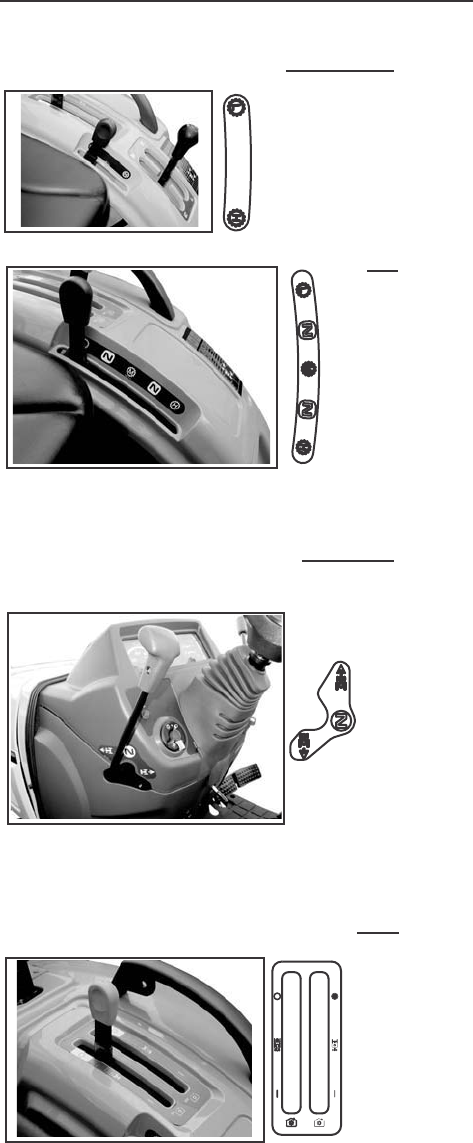
29
Control Levers
(Gear Drive)
(Hydrostatic Drive)
1.GEAR SHIFT LEVER (Gear Drive only)
The gear shift lever is used to shift the
transmission gears into any of four speeds.
3
1
2
2
3
INSTRUMENTS/CONTROLS
30
2. RANGE SHIFT LEVER Move the range shift lever forward
to place the transmission in H range.
Move the lever rear ward to place
the transmission in L range.
Move the range shift lever forward
to place the transmission in H range.
Move the lever to the rearward to
place the transmission in M or L range.
The center position between M and
L or H and M places the transmission
in N.
3-1. SHUTTLE SHIFT LEVER The shuttle shift lever is used to
shift the transmission gear into
forward of reverse position. Move
the shuttle shift lever forward
(F position) to the forward position.
Move the shuttle shift lever rearward
(R position) to the reverse position.
The center position between F and
R places the transmission in N position.
(neutral)
3-2. REAR PTO CONTROL LEVER Move the lever forward to engage
the REAR PTO. Move the lever
rearward to disengage the Rear
PTO.
NOTE: Be sure the Rear PTO
control lever is in OFF slot when
starting the engine.
NOTE: Be sure the range shift lever
is in N (Engine start) slot when starting
the engine.
NOTE: Be sure the shuttle shift lever
is in N (Engine start) position when
starting the engine.
(GEAR DRIVE ONLY)
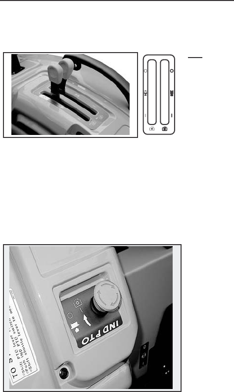
INSTRUMENTS/CONTROLS
31
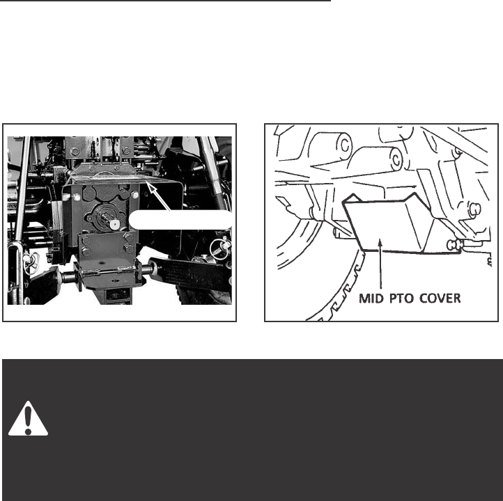
4. MID PTO CONTROL LEVER (IF EQUIPPED)
Move the lever forward to
engage the Mid PTO. Move the lever
rearward to disengage the Mid PTO.
NOTE: Be sure the Mid PTO
control lever is in OFF slot when
starting the engine.
NOTE:
1. The Rear and Mid PTO shaft can be operated at the same time.
2. When not using the Mid PTO shaft, cover the shaft with the Mid PTO cover.
PTO SWITCH PTO switch is used to engage or
disengage the Independent PTO
clutch. Turn right to engage push
to disengage.
(stop the turning of PTO shaft)
PTO indicator lamp in the meter
panel is illuminating when PTO is
in ON position.
PTO indicator lamp is not illuminating
when PTO is in OFF position.
NOTE: Be sure the PTO switch is
in OFF position when starting the
engine.
INSTRUMENTS/CONTROLS
32
(Gear Drive)
(Hydrostatic Drive)
5. HITCH CONTROL LEVER Use this lever to control the position of
the hitch. Move the lever forward to lower
the hitch to the required depth. Move the
lever to the rear to raise the hitch to the
required height.
5
5
INSTRUMENTS/CONTROLS
33
(Gear Drive)
(Hydrostatic Drive)
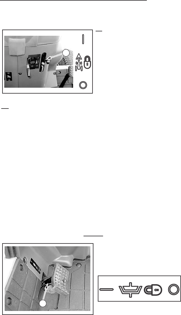
1. DIFFERENTIAL LOCK PEDAL
Push the pedal down to engage the differential lock. A spring inside the
differential lock will push it out of engagement when pedal is released.
GEAR DRIVE HYDROSTATIC DRIVE
1
3
2
2
1
3
INSTRUMENTS/CONTROLS
34
NOTE: When engaging the differential lock, push the clutch pedal down
or bring speed ratio control pedal to Neutral, to stop the wheels that are
rotating, then push the differential lock pedal. Do not engage the differential
lock pedal while the wheels are rotating.
Do not drive on roads, or at high speed anywhere, with the
differential lock engaged. Difficult steering will occur, and can result
in an accident. In field operation, use the differential lock for traction
improvement, but release for turning at row ends.
2. MFD CONTROL LEVER To engage the MFD (Mechanical
Front Drive), move the MFD control
lever downward. Move the lever upward
to disengage MFD (drive to the rear
wheels only).
IMPORTANT: The clutch pedal
must be pushed down to operate the
MFD lever.
3. HYDRAULIC FLOW CONTROL KNOB
Use the hydraulic flow control knob to adjust the hitch lowering speed.
Adjust the lowering speed to provide smooth operation of the hitch with
the implement being used. Turn the knob fully clockwise to lock the hitch
in position. See Hitch Lowering Speed Adjustment in this manual for
more information.
2WD
MFD
2WD
MFD
INSTRUMENTS/CONTROLS
35
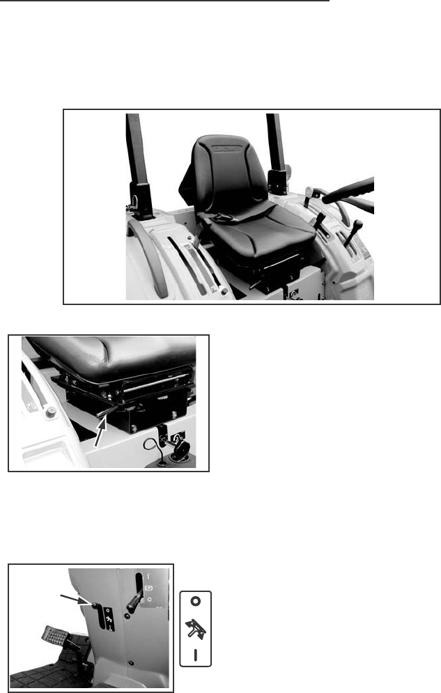
OPERATORS SEAT
The seat can be adjusted in 5 fore/aft position by the lever located under
the RH side of the seat.
The seat is adjustable fore and aft by moving a lever.
1. Move the lever upward.
2. Move the seat rearward or forward to
the required position then release the
lever.
3. Push the seat rearward to make sure
that the lock is engaged.
STEERING COLUMN TILT
The steering wheel angle can be adjusted
in three positions by the lever located under
the steering column.
To adjust the position of the steering wheel,
use following procedure.
1. Move the lever fully downward to
disengage the latch from the column.
2. Move the steering wheel rearward of
forward to the required position, then
return the lever upward to lock the
steering column.
3. Make sure that the lock is engaged.
STEERING
COLMN TILT
COLMN TILT
LEVER
STEERING
COLMN TILT
LEVER
SEAT
SEAT
ADJUSTING
LEVER
SEAT
ADJUSTING
LEVER

OPERATING INSTRUCTION
36
BEFORE STARTING THE ENGINE
Before starting your tractor for the first time and before each operating
period after that, make these checks:
1. Make sure all persons who operate or do maintenance on the tractor
understand that clean fuel is important.
2. Check all lubrication fittings for grease as given in the Lubrication Chart.
3. Check the oil level in the engine crankcase. Check the fluid level in the
transmission.
4. Check the tractor fuel tank is filled with clean fuel that has the
specifications given in this manual.
NOTE: Clean around the fuel tank cap before you remove cap.
5. Check the fuel system, cooling system and engine oil pan for leaks.
6. Check the fan belt is adjusted correctly.
7. Remove any water or sediment from the fuel filter cup.
8. Check the air pressure of the tires.
9. Make sure the PTO safety guard is installed.
10. Check the coolant level in the radiator and reservoir bottle.
Add water and ethylene glycol coolant as needed.

OPERATING INSTRUCTION
37
RUN – IN PROCEDURE
If run-in instructions for a new engine are not followed, you can cause
damage to piston rings and cylinder walls.
LOAD
Never operate an engine immediately under full load. Allow the engine to
warm up before operating it at full load. Run-in the engine carefully as
shown in the table.
NO LOAD
Do not run the engine at idle speed. When not operating the engine with
a load, you can keep the correct engine operating temperature if you run
the engine at approximately 1500 RPM.
REAR WHEEL BOLTS
After the first 10 hours of operation, check the rear wheel bolts. Tighten
all wheel bolts to the torque give in the Wheel Mounting Torques in this
manual.
FRONT WHEEL BOLTS
After the first 10 hours of operation, check the front wheel bolts. Tighten
the bolts to the torques shown in the Wheel Mounting Torques in this
manual.
FRONT FRAME BOLTS
After the first 10 hours of operation, check the front frame bolts. Tighten
the bolts to the torque shown below.
Front Frame Mounting Torques
Side (M12x35), 12Bolts (6LH and 6RH) … 83 to 93 Nm (61 to 69 lb ft)
LOWER LINK BRACKET BOLTS
After the first 10 hours of operation, check the Lower Link Bracket bolts.
Tighten the bolts to the correct tightening 39 to 44 Nm (29 to 33 lb ft).
Engine Speed
Control Lever
Position
Maintain engine speed
100 RPM above full load
governed speed
2nd
Full load governed
Through
speed with occasional
5th Hour
short periods of lighter load
Fully
advanced
Period Load
1st Hour Fully
advanced
OPERATING INSTRUCTION
NORMAL STARTING PROCEDURE
IMPORTANT: It is very important that enough lubricant reaches the engine
parts before operating the engine at rated speed.
38
Operate controls only when seated in the operators seat.
Engine can start with transmission in gear when neutral or safety
start switch is by-passed:
1. Do not connect across terminals on starter.
2. Attach a booster battery by connecting the positive terminal of
the booster battery to the “positive terminal” provided or to the
positive terminal of the machine battery. Connect the negative
terminal of the booster battery to the “negative terminal” provided
or to the chassis of the machine.
Then use recommended starting procedures from operators seat.
3. When necessary, repair electrical system components promptly
so that “jump starting” will not be attempted.
Machine run-away can cause injury or death to operator and
bystanders.
Before starting the engine, be sure all operating controls are in
neutral or park lock position. This will eliminate accidental
movement of the machine or start up of power driven equipment.
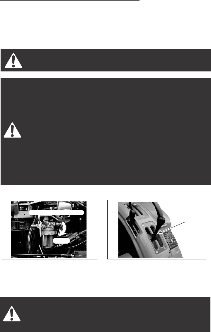
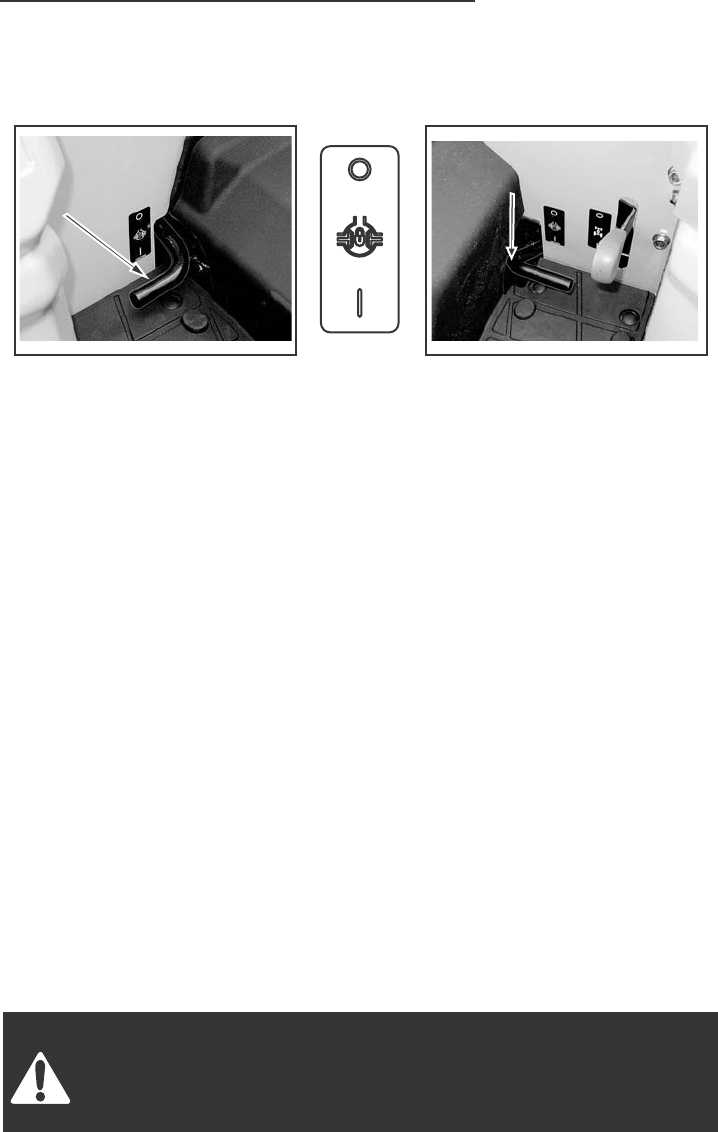
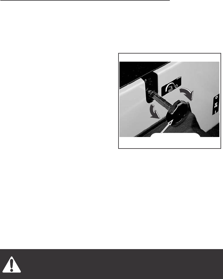
STEP 1
Make sure the fuel shut-off valve
is open. The valve is located at the
bottom RH side of the fuel tank.
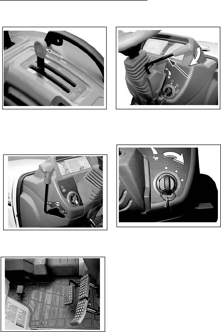
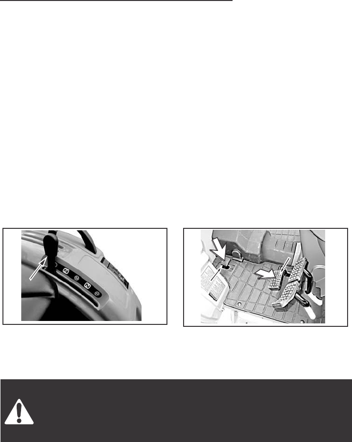
STEP 2
Put the gear shift lever in the
Neutral position (Gear Drive) or
the Speed Lock Lever to be released
(Hydrostatic Drive).
FUEL SHUT-OFF VALVE
FUEL SHUT-OFF VALVE
FUEL SHUT-OFF VALVE NEUTRAL
POSITION
OPEN
OPERATING INSTRUCTION
39
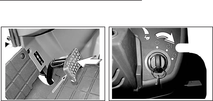
STEP 3 STEP 5
Put the REAR PTO and MID PTO
control levers in the OFF
(Engine start) position.
Put the engine speed control lever
at the middle position.
STEP 4
Put the SHUTTLE lever in the N
(Engine start) slot (Gear Drive).
STEP 6
Turn the starter key switch to the
heat & ON position.
Wait until the glow plug indicator lamp
is put out.
(Approximately 1 to 3 seconds.)
HST control pedal in the N position
CLUTCH pedal (HST Drive)
OFF
POSITION
OFF
POSITION
ENGINE
SPEED
CONTROL
LEVER
ENGINE
SPEED
CONTROL
LEVER
OPERATING INSTRUCTION
40
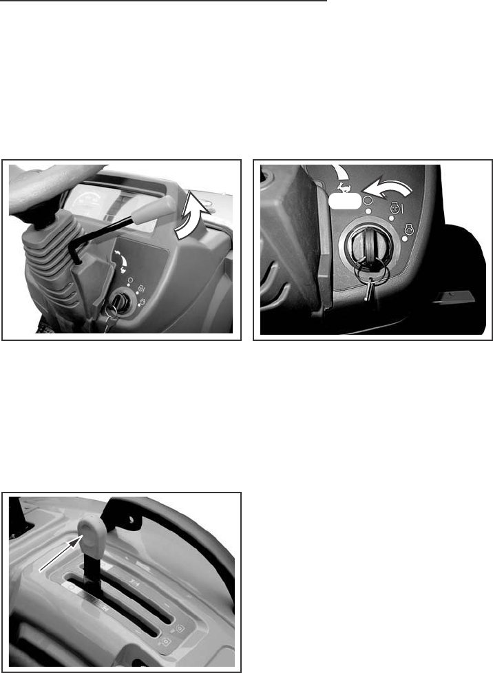
STEP 7
STEP 9
Push the clutch pedal down.
When the engine starts, check the
oil pressure indicators stay on, stop
the engine and find out what is wrong.
NOTE: If the oil pressure indicator stays on after the engine starts,
stop the engine and check the oil level in the crankcase. Add oil if necessary.
Start the engine, if the indicator is still on, do not operate the engine.
Operating the engine without oil pressure will damage engine bearings and
other engine parts. See your dealer.
IMPORTANT:
1. If the engine starts and then stops, wait for the starting motor to stop
turning before you turn the key switch to START position again.
CLUTCH PEDAL
CLUTCH PEDAL
CLUTCH PEDAL
STEP 8
Turn key switch to start position until
engine starts, but no more than
10 seconds, then release the key.
Run engine for two minutes at
1500 RPM.
START
2. Do not use the starter motor for more than 10 seconds without stopping.
Wait one minute between starts so the starter motor can cool.
3. If engine stops when operating with a load, immediately start the engine
again to prevent overheating caused by stopping the flow of oil for cooling
and lubrication.

OPERATING INSTRUCTION
41
Starting Procedure for Hydrostatic Drive Tractors
After Transporting on Truck or Flatcar
IMPORTANT: Hydrostatic transmission can jump into gear without warning,
if the fluid leaks out of the control system. This can occur due to vibration
if the tractor is transported on a truck or rail car. It can also happen if
the transmission is drained or if the tractor sits still for very long periods.
If any of these have happened, start the tractor as follows:
1. Put the range shift control lever into the N (Engine start) slot and release
the speed lock lever to permit the speed ratio control pedal to return to
N (Neutral) position.
2. Lock the brake pedals together, press down on the brake pedals.
3. Pull the engine speed control lever and start the engine. Set the engine
speed to about 1000 RPM.
4. Slowly move the range shift lever to H range for high speed engagement.
If gear clash is obvious the engine should be shut off immediately and
the tractor unloaded by other means. Tow the tractor with the range
shift lever in N(Neutral) to an area where the transmission can be checked
by your Dealer. Refer to Towing the Tractor in this manual.
If there is no obvious gear clash, drive the tractor in the normal manner.
4. If the charge indicator comes on during operation, determine and correct
the cause to avoid complete discharge of the battery and possible damage
to other components of the electrical system. See your Dealer.
5. If the coolant temperature indicator comes on, remove the load and
allow the engine to run at 1500 rpm until the indicator goes out.
If the indicator does not go out within one minute, stop the engine and
determine the cause.
OPERATING INSTRUCTION
STOPPING THE ENGINE
IMPORTANT: When stopping the engine after operating under heavy load,
run the engine at 1500 RPM for a short period of time. This will allow the
engine temperature to decrease gradually.
42
STEP 1
Move the engine speed control
lever to run engine at idle speed
for three to five minutes to decrease
the temperature of engine.
STEP 2
Put the REAR PTO control lever,
MID PTO control lever and the
range shift lever in the OFF or N
(neutral) position.
STEP 3
Turn the key switch to OFF position.
Remove the key.
STOP
STOP
STOP
OFF
REAR
PTO
PTO
REVER
REAR
PTO
REVER

OPERATING INSTRUCTION
COLD TEMPERATURE OPERATION
To start and operate your tractor during cold ambient temperatures, use
these procedures:
43
1. BATTERY – Must have a full charge.
2. FUEL – Must be clean and with no water. See Fuel Specifications in
this manual.
3. ENGINE OIL – Must have the correct viscosity for the ambient
temperature range.
4. TRANSMISSION HYDRAULIC FLUID – Use Cub Cadet Hydraulic
Transmission fluid.
5. COOLING SYSTEM – Must have ethylene glycol solution for protection.
6. TIRES – If there is liquid in the tires, the tires must have protection
against temperatures below 0 C(32 F). See your Dealer.
7. STOPPING THE ENGINE – Run the engine at idle speed for a short
period of time to permit the engine temperature to decrease before
stopping.
8. CONDENSATION IN FUEL TANK – To prevent condensation in the
fuel tank and water entering the fuel system, fill the fuel tank after each
operating day.
9. FUEL FILTER CUP – During cold ambient temperatures, make sure
you remove water from the fuel filter cup each day.
NOTE: Do not use ether as a cold temperature starting aid.

OPERATING INSTRUCTION
IMPORTANT: During cold ambient temperatures, never run the engine
at low idle speed for long periods of time.
44
During cold ambient temperatures, if the engine will not heat to or keep the
rated operating temperatures can cause damage to the engine can occur.
Use the following procedures to warm the engine and transmission fluids,
and to keep the correct operating temperatures.
1. WARMING THE ENGINE AND TRANSMISSION.
A. To heat the transmission fluid to operating temperature, run the
engine at 1500 RPM for approximately five minutes.
IMPORTANT: Operating the tractor with cold transmission fluid can
cause rough tractor operation with possible injury to the operator.
2. KEEP ENGINE AT CORRECT OPERATING TEMPERATURE.
A. Never run the engine below 1500 RPM.
B. Put a cover in front of the grille to control the amount of air going
through the radiator.
3. STOPPING THE ENGINE
A. Run the engine at slow speed for a short period of time. This will
permit the engine temperature to decrease gradually before stopping
the engine.

OPERATING INSTRUCTION
45
TOWING
When towing a tractor, follow these rules:
1. Never tow the tractor faster than a ground speed of 16 Km/h (10MPH).
2. Make sure all controls are in the neutral or OFF position.
3. Because of a possible loss of steering and brakes when the tractor engine
is not running, use only a rigid towing bar and safety chains to pull
the tractor.
Make sure that the weight of a trailed vehicle that is not equipped
with brakes, NEVER EXCEEDS the weight of the machine that is
towing the vehicle. Stopping distance increases with increasing
speed as the weight of the towed load increases, especially on
hills and slops.
HOW TO TRANSPORT TRACTOR
When you transport the tractor by truck or rail, follow these rules:
1. Hold the tractor with tie downs and block the wheels.
2. Gear Drive: Put the gear shift lever in 1 st position and put the range
shift lever in the L position and shuttle shift (over in F or R) position.
Hydrostatic Drive: Move the Speed Lock lever to OFF position and put
the range shift lever in the L position.
3. Lock the brake pedals together, push the brake pedals down and move
the park brake lever up to engage the park brake .
OPERATING INSTRUCTION
46
GEAR DRIVE TRANSMISSION
The gear drive transmission has forward and a reverse gear section,
a four-speed main shift gear section, and a three-speed range section.
This arrangement gives 8 forward and 8 reverse speeds.
Transmission Operation
1. Push the clutch pedal and stop the tractor. Move the gear shift lever to
the gear needed.
2. Move the range shift lever to the position needed, H, L (The tractor
must be stopped before the range lever is operated.)
3. Move the shuttle lever to Forward or Reverse position.
4. Release the clutch pedal slowly.
NOTE: When shifting from fourth to another range, be careful not to run
the engine at more than 2700 RPM.
IMPORTANT: Before selecting a new range, push the clutch pedal halfway
and stop the tractor. Do not change range when the tractor is moving.
OPERATING INSTRUCTION
47
HYDROSTATIC DRIVE TRANSMISSION
The Hydrostatic drive transmission has a forward/reverse hydrostatic section
and a three-speed range section. This arrangement gives three forward
and three reverse speeds ranges.
Transmission Operation
1. Push the clutch pedal fully and stop the tractor. Move the range shift
lever to the position needed, H, M or L.
2. Release the clutch pedal slowly.
3. Operate the speed ratio control pedal to move the tractor.
To shift from reverse to forward or from forward to reverse, move the
speed ratio control pedal without disengaging the clutch.
IMPORTANT: Before selecting a new range, stop the tractor and push
the clutch pedal. Do not change range when the tractor is moving.
Travel speed should be such that complete control and machine
stability is maintained at all times. Where possible, avoid operating
near ditches, embankments and holes. Reduce speed when turning,
crossing slopes, and on rough, slick, or muddy surfaces.
RANGE
SHIFT
LEVER
RANGE
SHIFT
LEVER
SPEED RATIO
SPEED RATIO
CONTROL
PEDAL
(REVERSE)
SPEED RATIO
CONTROL
PEDAL
(REVERSE)
SPEED RATIO
SPEED RATIO
CONTROL
PEDAL
(FORWARD)
(FORWARD)
SPEED RATIO
CONTROL
PEDAL
(FORWARD)
OPERATING INSTRUCTION
48
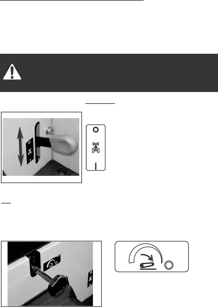
DIFFERENTIAL LOCK
GEAR DRIVE
RIGHT SIDE of the transmission
HYDROSTATIC DRIVE
LEFT SIDE of the transmission
Your tractor has a differential lock that will make both rear wheels turn at
the same speed. The differential lock prevents loss of power when
one wheel does not have traction but the other wheel does have traction.
It also provides a straight in line steering aid when opening up the field
and to control implement overlap.
TO ENGAGE THE DIFFERENTIAL LOCK:
Depress and hold the differential lock pedal down.
IMPORTANT: Do not engage the differential lock while one rear wheel is
rotating and the other rear wheel is stopped. Always stop the wheel that is
rotating and then engage the differential lock.
IMPORTANT: When you engage or disengage the differential lock, the front
wheels must be in the straight forward position. Before turning the tractor,
disengage the differential lock.
TO DISENGAGE THE DIFFERENTIAL LOCK:
The differential lock will disengage when the differential lock pedal is
released. If the differential lock does not disengage easily, push down on
either brake pedal momentarily.
Do not drive on roads, or at high speed anywhere, with the
differential lock engaged. Difficult steering will occur, and can result
in an accident. In field operation, use the differential lock for
traction improvement, but release for turning at row ends.
DIFFERENTIAL
LOCK PEDAL
LOCK PEDAL
DIFFERENTIAL
LOCK PEDAL
DIFFERENTIAL
LOCK PEDAL
LOCK PEDAL
DIFFERENTIAL
LOCK PEDAL
OPERATING INSTRUCTION
49
POWER TAKEOFF (PTO)
PTO driven machinery can cause serious injury or death, usually due
to wrapped clothing. When required by the job to be in the
drive shaft area, stay clear of rotating parts. Before working on the
drive shaft, or servicing or clearing the driven machine, where
applicable on this tractor, put the PTO clutch lever in the DISENGAGE
position, the PTO lever in the NEUTRAL or OFF, and STOP the engine.
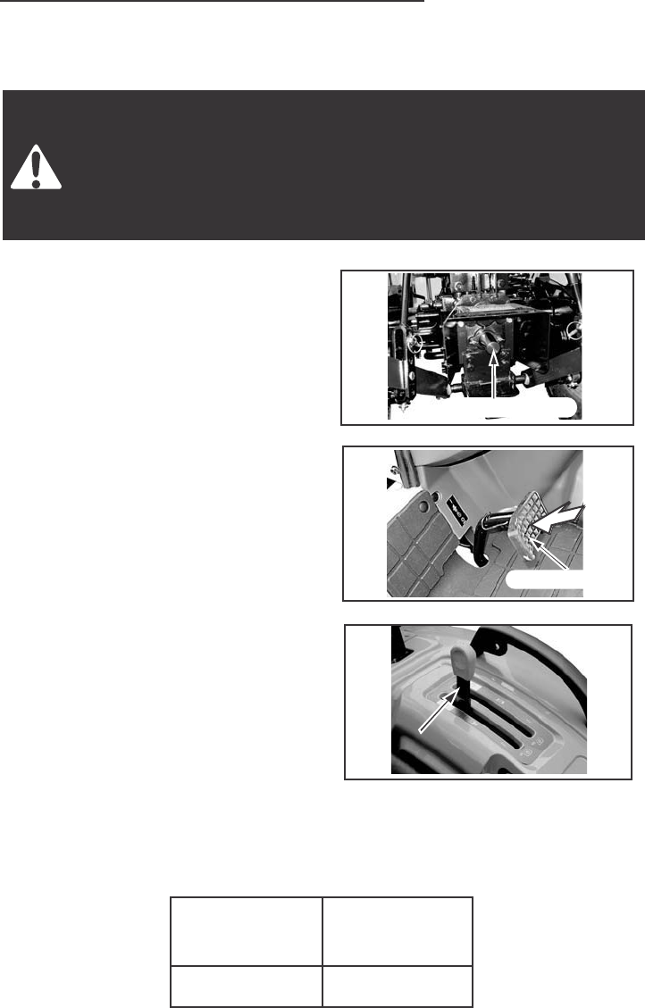
Rear PTO (HST)
The rear PTO is a 540 RPM with a
34.9 mm (1 3/8 inch) diameter 6
spline output shaft.
ENGAGE THE REAR PTO AS
FOLLOWS:
1. Push the clutch pedal fully.
2. Move the PTO control lever to the
ON position.
3. Release the clutch pedal slowly.
DISENGAGE THE REAR PTO
AS FOLLOWS:
1. Push the clutch pedal fully.
2. Move the PTO control lever to the
OFF (Engine Start) position.
NOTE : Keep the PTO control lever
in the OFF (Engine Start) position
when starting the engine and when
the PTO is not being used.
3. Release the clutch pedal slowly.
The following table shows the required speed to get the required Rear
PTO output shaft speed.
PTO Output
Shaft Speed
540 RPM
Required
Engine Speed
2376 RPM
REAR PTO SHEFT
REAR PTO SHEFT
CLUTCH PEDAL
CLUTCH PEDAL
REAR PTO
REAR PTO
CONTROL LEVER
CONTROL LEVER
REAR PTO
CONTROL LEVER
REAR PTO SHAFT
CLUTCH PEDAL
OPERATING INSTRUCTION
50
POWER TAKEOFF (PTO)
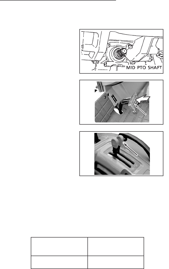
Mid PTO (OPTION)
The Mid PTO has a 25.4 mm
(1 inch) diameter 15 spline
output shaft.
ENGAGE THE MID PTO AS
FOLLOWS:
1. Push the clutch pedal fully.
2. Move the Mid PTO control
lever to the ON position.
3. Release the clutch pedal
slowly.
DISENGAGE THE MID PTO
AS FOLLOWS:
1. Push the clutch pedal fully.
2. Move the Mid PTO control
lever to the OFF (Engine Start)
position.
NOTE: Keep the Mid PTO
control lever in the OFF (Engine Start)
slot when starting the engine and when
the PTO is not being used.
3. Release the clutch pedal.
The following table shows the required engine speed to get the required
Mid PTO output shaft speed.
Mid PTO Output
Shaft Speed
2000 RPM
Required
Engine Speed
2526 RPM
MID PTO
MID PTO
LEVER
MID PTO
LEVER
CLUTCH
PEDAL
CLUTCH
PEDAL
OPERATING INSTRUCTION
51
POWER TAKEOFF GUARDS
All tractors have a safety guard for the Rear PTO shaft and safety cover
for the Mid PTO shaft.
Whenever a PTO driven machine is in operation, the PTO guard
must be in place for most operations to prevent injury to the operator
or bystanders. Where attachments, such as pumps, are installed on
the PTO shaft (especially if the tractor PTO guard is moved upward
or removed) extended shielding equivalent to the PTO guard must be
installed with the attachment. Install the PTO guard to its original
position immediately when the attachment is removed.
REAR PTO GUARD

OPERATING INSTRUCTION
52
PTO OPERATING SAFETY
For the safe operation of the PTO, follow these safe operating procedures.
Three Point Hitch Connecting Implements
1. Connect the implement to the hitch.
See THREE POINT HITCH SYSTEM in this manual.
2. Connect the implement driveline to the tractor.
3. Check the driveline for correct length and for free telescopic movement
by lifting and lowering hitch system. The correct length is important to
prevent the driveline from hitting bottom or from separating in any tractor
implement operating position.
Drawbar Connecting Implements
1. Connect the implement hitch to the drawer with a hardened steel pin.
Make sure the pin is securely held in place with a cotter pin or lock pin
and does not make contact with the implement driveline.
2. Connect the implement hitch to the tractor drawbar before connecting the
implement driveline to the PTO.
3. Connect the implement driveline to the tractor. Check the driveline for
correct length and for free telescopic movement. The correct length is
important to prevent the driveline from hitting bottom or from separating
in any tractor or implement operating position.
When doing stationary PTO work and dismounting from the tractor
with the PTO running, keep clear of all moving parts as they are
a potential safety hazard.
IMPORTANT: Follow the implement manufacturers recommendations in
adjusting and aligning the implement and implement driveline with the tractor.
PTO driven machinery can cause serious injury. Before working on
or near the PTO shaft, or servicing or clearing the driven machine,
put the PTO lever in the DISENGAGE position and STOP the engine.
OPERATING INSTRUCTION
53
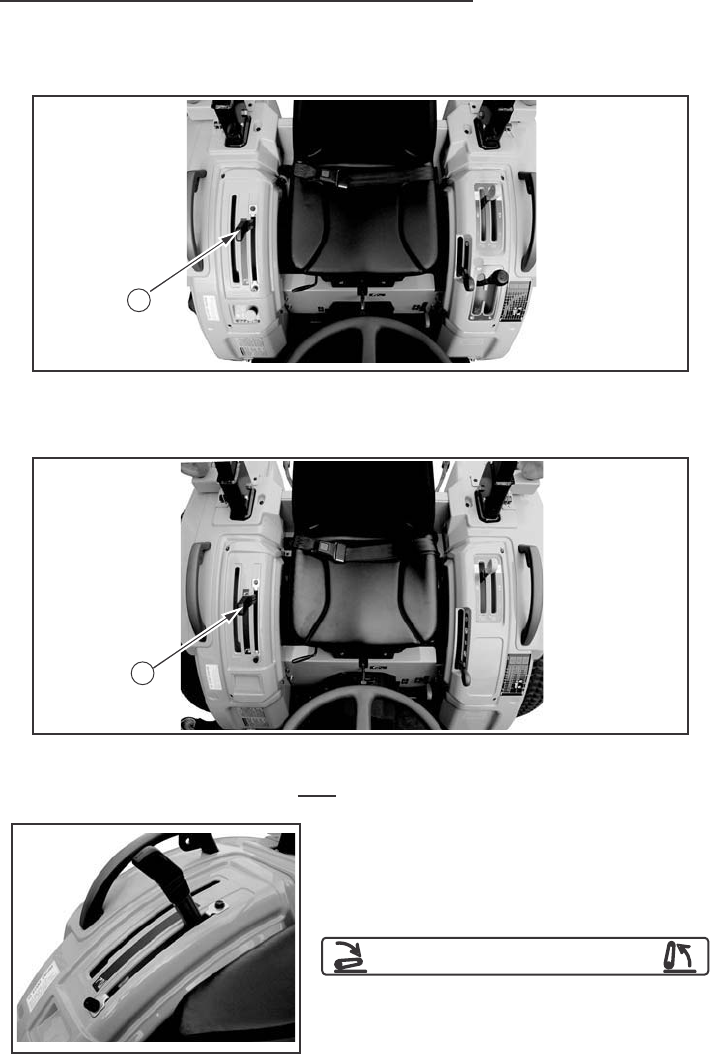
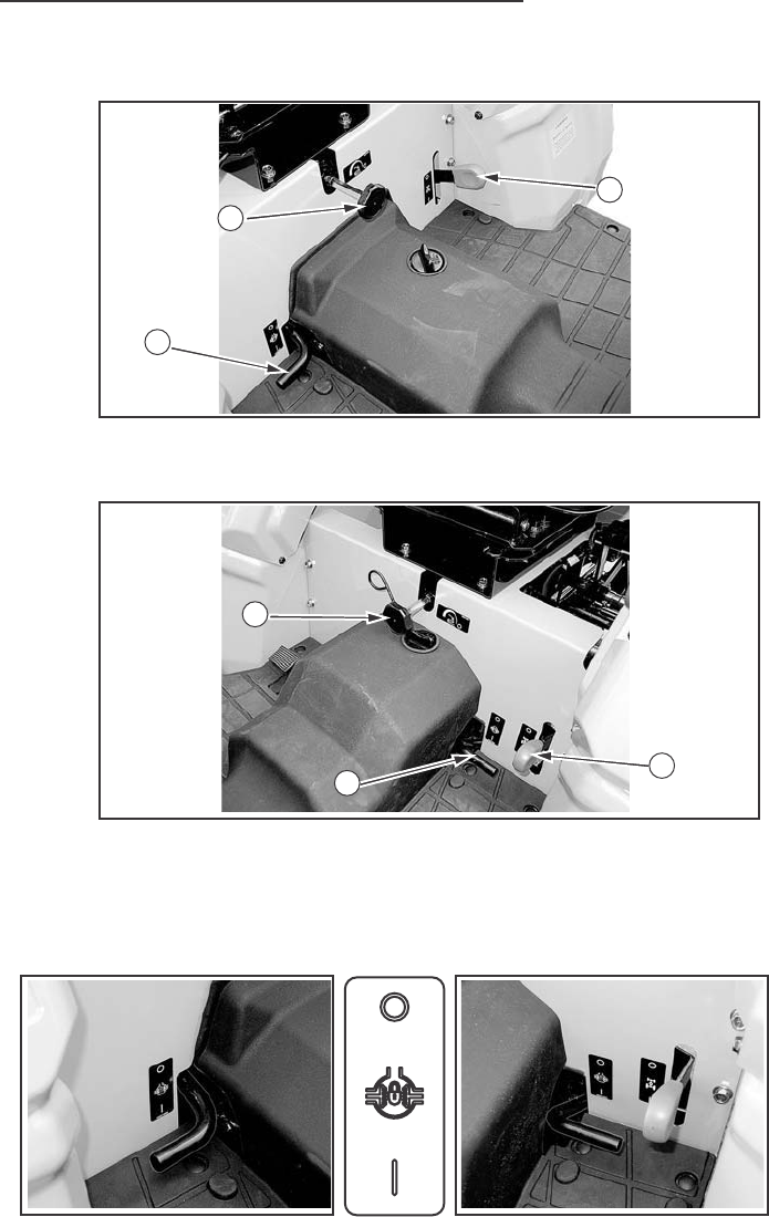
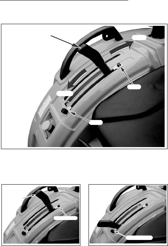
DRAWBAR
Your tractor is equipped with a drawbar. Use the drawbar for connecting
all pull-behind implements.
The drawbar must be in the storage position when using the three-point hitch.
Try to balance the load primarily on the implement wheels –as in
loading a trailer or spreader. Avoid overloading the drawbar. Add
front end weights for improved stability. Engage the clutch smoothly,
avoid jerking and use the brakes cautiously to avoid jackknifing.
Rear upset can result if pulling from wrong location on tractor.
Hitch only to the drawbar. Use 3 point hitch only with the implements
designed for its use – not as a drawbar.
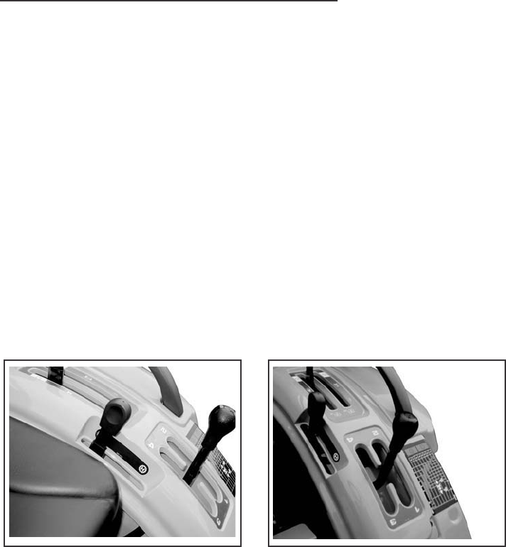
WITH MID PTO WITHOUT MID PTO
DRAWBAR
OPERATING
POSITION
IMPLEMENT CONNECTING
PIN HOLE
DRAWBAR HITCH
CONNECTING PIN HOLE
STORAGE PIN HOLE
WITHOUT MID PTO
STORAGE POSITION
STORAGE POSITION
(WITH MID PTO)
(WITH MID PTO)
STORAGE POSITION
(WITH MID PTO)
STORAGE POSITION
(WITHOUT MID PTO)
OPERATING INSTRUCTION
54
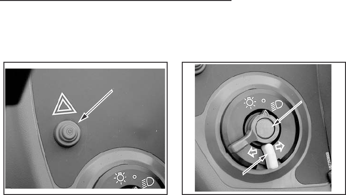
WARNING LAMPS
The lamp switch has two positions. Turn the switch clockwise to
illuminate the headlamp, rear red lamp, and instrument panel lamps.
Push the flasher control button down to operate the amber warning lamps.
When the turn signal switch is moved upward to make a right turn,
the RH warning lamp will illuminate ON and OFF and the LH lamp will
illuminate continuously.
When the turn signal switch is moved downward to make a left turn,
the LH warning lamp will illuminate ON and OFF and the RH lamp will
illuminate continuously.
When the turn signal switch is returned to the center position, both
warning lamps will illuminate ON and OFF.
IMPORTANT: When towing an implement or wagon with the tractor,
the complete rear area warning system (amber warning lamps, rear
red lamp and SMV emblem) must be easily seen by any vehicle operator
coming near the tractor.
FLASHER
CONTROL BUTTON
CONTROL BUTTON
LAMP
SWITCH
TURN
SIGNAL
SWITCH
FLASHER
CONTROL BUTTON LAMP
SWITCH
TURN
SIGNAL
SWITCH
FIELD OPERATION
55
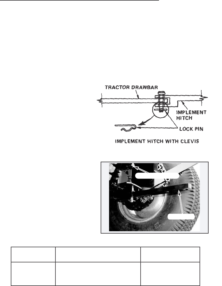
CONNECTING IMPLEMENT TO DRAWBAR
The correct connection of the implement to the drawbar will prevent stress
on both the tractor and the implement.
To assure proper tractor operation and optimum implement performance,
the implement must be connected to the drawbar correctly.
1. Connect pull-behind implements to the drawbar only.
2. Use a hardened steel hitch pin
to connect the implement to
the drawbar. Make sure the pin
is held securely in place with
a lock pin.
3. When working with the drawbar,
raise the lower links as high as
possible to prevent interference
between the lower links and
the implement.
4. The drawbar provides the
standard hitch distance from
the end of the PTO shaft to
the centerline of the rear hole
in the drawbar. This is necessary
for safe PTO operation of trailing
type equipment.
IMPORTANT: The maximum fixed drawbar vertical load is 440 Kg
PTO RPM
540
PTO SHAFT DIAMETER
1.375 In
(34.9 mm)
DIMENSION A
14 In
(358 mm)
REAR PTO SHAFT
REAR PTO SHAFT
REAR PTO SHAFT
DRAWBAR
FIELD OPERATION
56
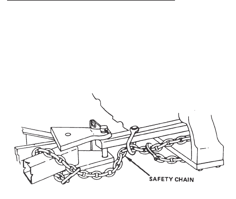
SAFETY CHAIN
When towing equipment on a highway, use a safety chain as an auxiliary
connection between the tractor and the towed equipment. The safety chain
must have a rating greater than the gross load of the towed equipment.
Connect the chain to the tractor drawbar support and the towed equipment
as shown in the illustration. Check the adjustment of the safety chain by
turning the tractor completely to the right and left. Adjust the chain
as necessary.
FIELD OPERATION
57
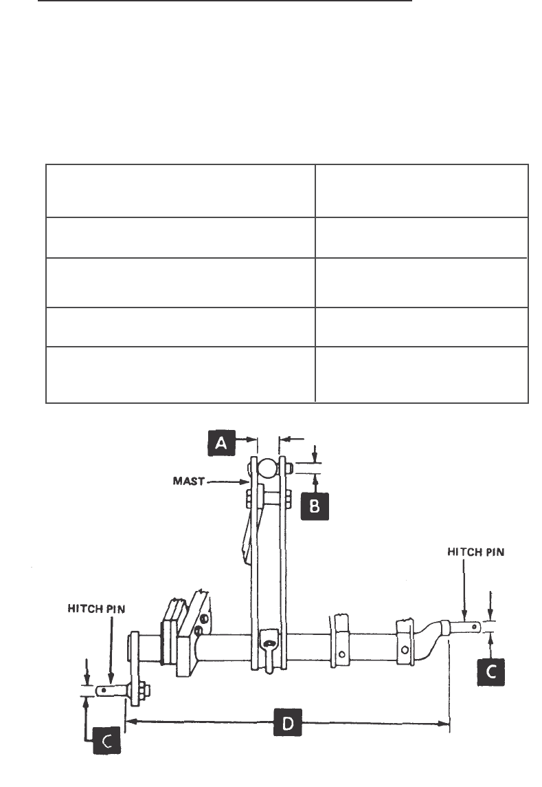
THREE POINT HITCH SYSTEM
The three point hitch system gives position control and draft control (If
equipped) of implements. This tractor is equipped with a category I hitch.
The three-point hitch dimensions are shown in the following table.
Implement Identification
Dimensions
A – Gap in top of implement mast
B – Diameter of holes in top of
Implement mast
C – Diameter of hitch pins
D – Lower Hitch Pin
Inner Shoulder Spread
Cat I
Implement
44.5 mm (1-3/4 inch)
19.1 mm (3/4 inch)
22.2 mm (7/8 inch)
682.6 mm (26-7/8 inch)
FIELD OPERATION
58
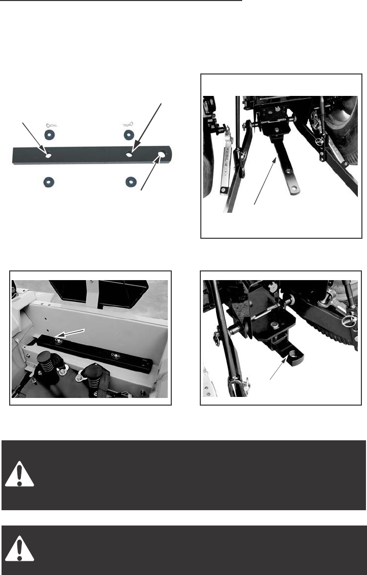
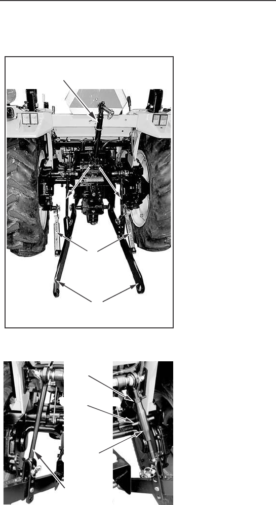
HITCH SYSTEM ADJUSTMENTS
The upper and lower links must be
adjusted correctly so the implement
can work at the needed depth and the
links are free to move up and down
with the shape of the ground.
1. Connect the lift links to the tractor
and to the lower links. Make sure
the lift links are installed on the
proper Sides as shown below.
2. The RH side lift link is adjustable
by turnbuckle to obtain the desired
position of the hitch point.
Turn the turnbuckle clockwise to
shorten the link or counterclockwise
to lengthen the link.
IMPORTANT: After the lift link is adjusted, make sure the locknut is
tightened against the turnbuckle.
LOCK NUT
Lift Links
UPPER
LINK
LOWER LINKS
LIFT
LINKS
LIFT
LINKS
STABILIZERS
TURN BUCKLE
LH LIFT LINK
RH LIFT LINK
FIELD OPERATION
59
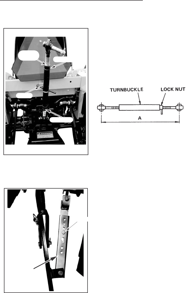
Upper Link
The length A of the upper link can be
adjusted from 470 to 750 mm (18.5 to
29.5 inches).
Turn the turnbuckle clockwise to
shorten the link or counterclockwise
to lengthen the link.
IMPORTANT: After the upper link is correctly adjusted, make sure the
lock nut is tightened against the turnbuckle.
Stabilizer When side movement of the hitch is
undesirable or hazardous, the lateral
swing is adjusted by select hole on
the stabilizer.
Slide REAR STABILIZER and adjust
hole REAR and FRONT STABILIZER
set clevis pin the hole.
IMPORTANT: After making final
adjustments carefully raise the
implement to make sure that there is
proper clearance between the
implement and tractor components.
NOTE: Insert pin to hole in clevis pin
surely.
UPPER
LINK TURNBUCKLE
HOOK
LOCK NUT
SLIDER PLATE
LOCK PIN
HOOK
TURNBUCKLE
UPPER
LINK

FIELD OPERATION
60
HITCH OPERATION
Connecting Implement to Hitch
To connect an implement to the hitch, use the following procedure:
NOTE: Be sure the tractor and implement are on level ground.
1. Put the drawbar in the storage position.
2. Slowly move the tractor backwards to the implement.
3. When the hitch points on the tractor and implement are in the correct
position, stop the tractor.
4. Apply the park brake and stop the engine.
5. Connect the implement to the Upper and Lower Links.
6. Adjust the Upper and Lower Links as necessary. See Hitch System
Adjustments in this manual.
Disconnecting Implement from Hitch
To disconnect an implement from the hitch, use the following procedure:
NOTE: Be sure the tractor and implement are on level ground.
1. Stop the tractor completely and apply the park brake.
2. Disengage the PTO, lower the implement to the ground.
3. Gear Drive: Place the gear shift and range shift levers in Neutral.
Hydrostatic Drive: Release the speed lock lever, and place the range
shift lever in Neutral.
4. Stop the engine and remove the key from the key switch before leaving
the tractor.
5. Disconnect the implement from the hitch.
NOTE: Be sure the tractor and implement are stable and free from any
tendency to roll over.
FIELD OPERATION
61
Hitch Control Lever
The hitch control lever is used to raise or lower the implement mounted to
the three point hitch. To raise the hitch, move the lever to the rear. To lower
the hitch, move the lever forward.
Adjustable stops are provided for use whenever it is desirable to return the
hitch control lever to the same operating position.
IMPORTANT: Position of the raise stop should not be set so rearward that
insufficient free play of the lift arms is available at the highest position
when hitch control lever is moved to the raise stop.
HITCH CONTROL LEVER
STOP
STOP
HITCH
CONTROL
LEVER
RAISE STOP
LOWER STOP
LOWER
RAISE
FIELD OPERATION
62
Hitch Lowering Speed Adjustment
To adjust the hitch lowering speed, use the following procedure:
1. Move the hitch control lever forward
to lower the implements.
2. Turn the hydraulic flow control knob
to adjust the lowering speed. Turn
the knob counter clockwise to
increase the lowering speed. Turn
the knob clockwise to decrease
the speed or lock the hitch.
3. After adjusting the speed, raise
the hitch and then lower it to check
the speed.
NOTE: When transporting the tractor on the road with the implement
mounted on the three point hitch, always set flow control knob to the
LOCK position.
IMPORTANT: Never park a tractor with an implement in the raised position.
Moving the control lever forward will lower the implement even though the
engine is not running. If it is necessary to service the implement in the
raised position, use jack stands to safely block the implement in place.
Put the hydraulic flow control knob in the LOCK position.
Lower or block elevated implements and other attachments before
servicing or when leaving the equipment.
HYDRAULIC FLOW
CONTROL KNOB
SLOW
LOCK
SLOW
LOCK
FAST
FAST
FAST
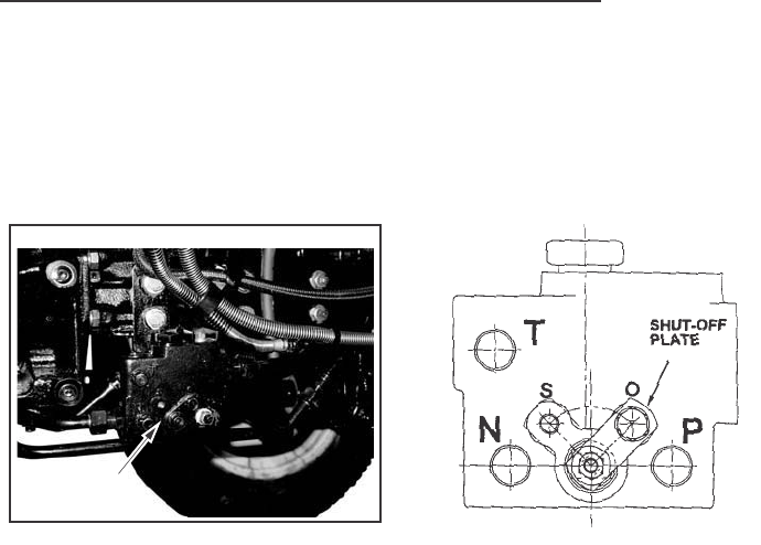
FIELD OPERATION
63
HYDRAULIC BLOCK
A hydraulic block is located on the right side of the tractor. This block can
provide an external hydraulic circuit for loader use or other applications.
See your dealer.
IMPORTANT: Never park a tractor with an implement in the raised position.
Moving the control lever forward will lower the implement even though the
engine is not running. If it is necessary to service the implement in the raised
position, use jack stands to safely block the implement in place. Put the
hydraulic flow control knob in the LOCK position.
IMPORTANT: Whenever the shut off plate is set at the “S” position, never
plug the inlet and outlet of the Hydraulic block. Change the set position of
shut - off plate to “O” position, if the remote attachment is not installed.
Failure to do so will cause damage to the hydraulic system.
HYDRAULIC
BLOCK
HYDRAULIC
BLOCK

FIELD OPERATION
64
Adding Fluid after Connecting Cylinders and Hoses
Operate the engine at a moderate idle speed. Set the stroke stop at the
yoke end of the cylinder rod to provide maximum stroke. Then operate the
cylinder in both directions about ten times, by moving the control lever
up and down.
This will fill the cylinder and hoses with fluid and remove the air from the
system. Fill the cylinder completely, stop the engine and check the fluid level
with the transmission dipstick.
Add sufficient, clean specified fluid to bring the oil up to the proper level.
See TRANSMISSION AND HYDRAULIC LUBRICATION in this manual.
NOTE: If any of the hydraulic units are removed and replaced for any reason,
check the oil level and add the specified fluid to the transmission to bring
the oil up to the proper level.
When remote cylinders are connected to the hydraulic system, cycle
the control lever about three times to remove air from the cylinder
and hoses. With air in the system, raised equipment can drop
accidentally and cause personal injury or machine damage.
Hydraulic oil or diesel fuel leaking under pressure can penetrate the
skin and cause infection or other injury.
To Prevent Personal Injury:
Relieve all pressure, before disconnecting fluid lines.
Before applying pressure, make sure all connections are tight and
components are in good condition.
Never use your hand to check for suspected leaks under pressure.
Use a piece of cardboard or wood for this purpose.
If injured by leaking fluid, see your doctor immediately.
The implement should be lowered to the ground before uncoupling
of the remote hydraulic hoses.
Lower or block elevated implements and other attachments before
servicing or when leaving the equipment.
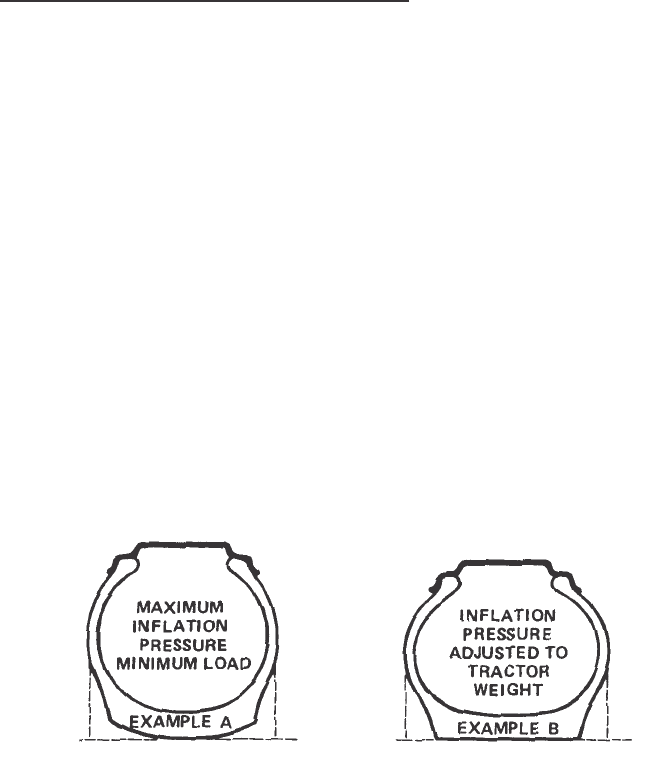
TIRES/WHEELS/SPACING/BALLAST
65
Lower or block elevated implements and other attachments before
servicing or when leaving the equipment.
TIRE AND RIM EQUIPMENT
Tire Inflation Specifications
Tire pressure can also be adjusted as required to safely meet the following
requirements.
A. Severe Service. Tire pressure can be increased 28 kPa (4 PSI) more
than the maximum pressure shown in the chart, for tires used in severe
service. Severe service includes the furrow tire in regular plowing
operations, the downhill tire in plowing and in other hillside operations.
B. Tires With Liquid Ballast. Inflate the tires 14 kPa (2 PSI) more than
the recommended pressure. This will compensate for aeration that
occurs when the tires are in motion.
IMPORTANT: During transportation on a railroad car or trailer, the tractor
tires are often inflated to higher than normal operating pressures. Before
using your tractor check the air pressure in the tires to make sure that
the air pressure does not exceed the maximum pressures shown in the tire
and wheel equipment chart.
For normal tractor operation use the inflation pressure shown in the tire
and wheel chart. The inflation pressure are based on cold inflation pressure
recommendations by Tire and Rim Association Inc.
For maximum tractor performance always adjust the tire pressure, within
the minimum/maximum range to conform with the actual load on the tires.
Under normal conditions use the minimum pressure rating for general
drawbar work. Use the higher pressure rating, up to the maximum, for heavy
three point hitch mounted equipment, or heavy front and mounted equipment.
Example A shows the cross section of a tire inflated for maximum load but
with a minimum load on the tire. The tire tread is not making full contact
with the ground which will give poor performance.
Example B shows the cross section of a tire with inflated pressure correctly
adjusted to the load on the tire. The tire tread is making full contact with
the ground which will give maximum performance.

TIRES/WHEELS/SPACING/BALLAST
66
A tire can explode during inflation and cause serious injury or
death. Never increase air pressure beyond 35 PSI to seat the
bead on the rim. Replace a tire if it has a direct. Replace a wheel
rim which has cracks, wear or severe rust. Make sure that all the
air is removed from a tire before removing the tire from the rim.
Never use force on an inflated or partially inflated tire. Make sure
the tire is correctly seated before inflating.
Tire Load Capacity
The maximum load capacity, shown in the tire pressure and load capacity
chart, is of the wheel with the tire inflated to the maximum pressure. Do not
exceed the maximum load capacity of the tire.
Rear
Front
9.5-24 6 PLY R-1 24 2070 LBS 30 PSI
13.6-16 4 PLY R-4 W 10 L 1750 LBS 14 PSI
11.2-24 4 PLY R-1 24 W 10 1860 LBS 18 PSI
41x14-20 4 PLY SofTrac 20x11 3120 LBS 25 PSI
MAX.LOAD
CAPACITY AT
MAX.INFLATION
PRESSURE
INFLATION
PRESSURE
TIRE
SIZE
TIRE
RATING
TREAD
TYPE
RIM
SIZE
7-14 4 PLY G-1 14x5 815 LBS 26 PSI
25x8.5x14 4 PLY G-2 8.0 1240 LBS 22 PSI
6.7-15 4 PLY I-3 15x5 1300 LBS 32 PSI
25x10.5-15 4 PLY SofTrac 15x8 1305 LBS 25 PSI
27x10.5x14 4 PLY SofTrac 15x8 1740 LBS 30 PSI
INFLATION
PRESSURE
MAX.LOAD
CAPACITY AT
MAX.INFLATION
PRESSURE
TIRE
SIZE
TIRE
RATING
TREAD
TYPE
RIM
SIZE

TIRES/WHEELS/SPACING/BALLAST
67
Check Air Pressure
Tire Pressure Check Interval Every 50 hours of operation or weekly.
Check the condition of the tires and rims for wear or damage. Keep the
tires inflated to the recommended pressures. See Tire and Wheel
Specifications in this manual for recommended inflation pressures for
each tire size.
For tires equipped with liquid ballast, check the air pressure as follows:
1. Use an air-water gauge. The valve must be at the bottom of the tire to
get an accurate reading.
2. Use a standard air gauge as follows:
A. The valve must be at the top of the tire.
B. Measure the rim diameter.
C. Add 3.5 kPa (1/2 PSI) for each 305 mm (12 inches) of rim diameter
to the standard gauge reading.
Tire Inflation Procedure
A tire can explode during inflation and cause serious injury or
death. Never increase air pressure beyond 35 PSI to seat the
bead on rim. Replace a tire if it has a defect. Replace a wheel
rim which has cracks, wear or severe rust. Make sure that all the
air is removed from a tire before removing the tire from the rim.
Never use force on an inflated or partially inflated tire. Make sure
the tire is correctly seated before inflating.
DO NOT inflate a tire that has had a complete loss of air. If the tire has
lost all air pressure, have a qualified tire mechanic service the tire.
To ADD air to a partly inflated tire, use the following procedure:
1. Use an air hose with a remote shutoff valve and a self – locking air chuck.
2. Stand behind the tread of the tire and make sure all persons are away
from the side of the tire before you start to add air.
3. Inflate the tire to the recommended air pressure. DO NOT inflate the
tire more than the recommended pressure.
NOTE: Tires can be inflated 28 kPa (4 PSI) over maximum recommended
in chart when tractor is used for heavy draft operation and ground compaction
is not a problem.

TIRES/WHEELS/SPACING/BALLAST
68
WHEEL MOUNTING TORQUES
Front Wheel Disc to Axle Hub Bolts
147 to 166 Nm (87 to 98 lb ft)
Rear Wheel Disc to Axle Hub Bolts
147 to 166 Nm (87 to 98 lb ft)
152 to 172 Nm (112 to 127 lb ft)
IMPORTANT: Check the wheel bolts and nuts after the first 10 hours of
operation and again after every 100 hours of operation. Also do this
procedure any time the wheel or rim is removed.
Rear Wheel Rim to Wheel Disc Nuts
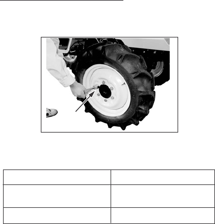
TIRES/WHEELS/SPACING/BALLAST
69
FRONT WHEEL ADJUSTMENT
The front wheels are tightened with six bolts for MFD to the axle hubs.
Torques for wheel bolts and tie rod end nuts as follows:
Check the bolts to keep them tight at the intervals recommended in the
Service Chart in this manual.
NOTE: The front wheel of tires must always be assembled with the
valve side out.
BOLTS AND NUTS POSITIONS
Front wheel disc
to axle hub bolts
Tie rod end nuts
TORQUE
147 to 166 Nm (109 to 123 LB FT)
59 to 88 Nm (43 to 65 LB FT)
109 to 123 LB FT
(147 to 166 Nm)
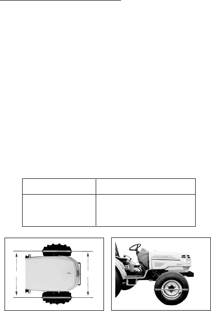
TIRES/WHEELS/SPACING/BALLAST
70
Toe-in Adjustment
TO CHECK THE TOE-IN, USE THE FOLLOWING PROCEDURE:
1. Put the tractor on level ground and the wheels in the straight-ahead
position.
2. Place chalk marks at points A on the centerlines of both front tires at
the same height as the centerline of the hubcap.
3. Measure the distance (L1) between the chalk marks at points A.
4. Move the tractor forward a distance equal to one-half revolution of the
front wheels.
5. The chalk marks will now be at points B. Measure the distance (L2)
between the chalk marks at points B.
6. The figure of L1minus L2is the toe-in. Make sure the toe-in is adjusted
properly. If not, adjust the toe-in.
FRONT AXLE TYPE
MFD
TURN THE WHEELS
ONE-HALF
REVOLUTION
TOE-IN (L1-L2)
0 TO 0.20 INCH (0 TO 10 mm)
L2
L1
AB
AB
AB
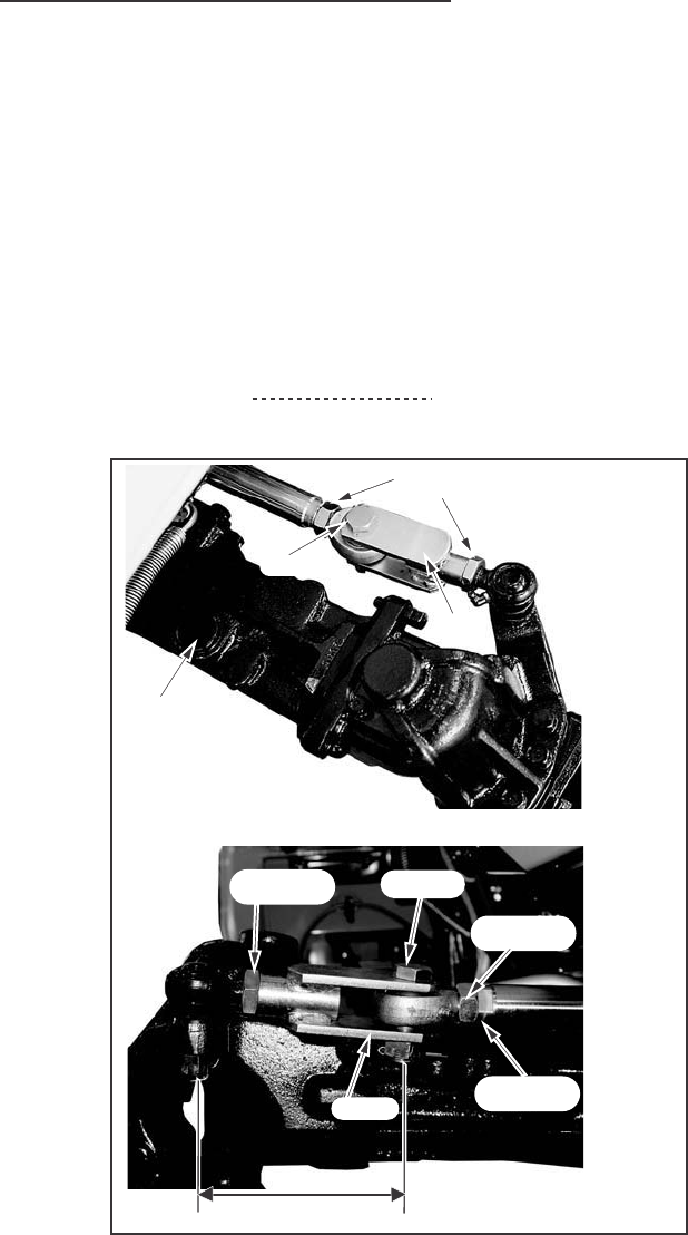
TIRES/WHEELS/SPACING/BALLAST
71
TO ADJUST THE TOE-IN, USE THE FOLLOWING PROCEDURE:
Adjust the rods to be equal the dimensions A on both side.
1. Loosen the lock nut at the rod end.
2. Turn the rod to shorten or lengthen the tie rod.
3. Look the lock nuts.
Tightening torque 147 to 166 Nm (109 to123lbft)
(RH SIDE)
(RH SIDE)
LOCK NUT
ROD END
BOLT
LOCK NUT
ROD
LOCK NUT
BOLT
ROD
FILL HOLE
A
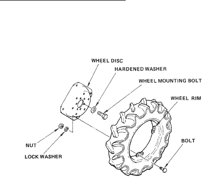
TIRES/WHEELS/SPACING/BALLAST
72
Tractor Equipped with Adjustable Wheels
If you need to change the position of the discs and rims of the wheels,
use the following procedure:
1. Put blocks at the front wheels, lift the rear of the tractor and put blocks
under the tractor.
2. Remove six wheel mounting bolts at each wheel to remove rear wheels
from rear axle.
3. Remove wheel disc from the wheel rim at each wheel.
4. Install the wheel discs and rims in the required position shown in the
Rear Wheel Tread Positions in this manual.
5. Tighten the wheel rim to wheel disc nuts to a torque of 152 to 172 Nm
(112 to 127 lb ft).
6. Put the rear wheels on the rear axle and tighten the wheel mounting
bolts with hardened washers to a torque of 118 to 132 Nm (87 to 98 lb ft).
NOTE: When putting the wheels on the axle, make sure that the tires rotate
in the correct direction. See Tire Installation in this manual.
IMPORTANT: When adjusting wheels, check nut and bolt torques after
10 hours of operation and every 100 hours thereafter.

TIRES/WHEELS/SPACING/BALLAST
73
TIRE SIZE COMBINATIONS-MFD
Your MFD Tractor must use front and rear tire combinations that are
correctly matched. The use of recommended tire combinations will give
maximum tractor performance, extended tire and reduced wear on
drive train components.
IMPORTANT: The tire size combinations shown below are specified to
provide matched ground speeds of the front and rear tires. Mixing worn
and new tires or tires of different diameters or loaded radii can give incorrect
ground speed match. When replacing tires, consult your Dealer.
MODEL NUMBER
7530/7532
TIRE
Front
Rear
Front
Rear
SIZE
7-14
9.5-24
25x8.5-14
13.6-16
STYLE
R1*
RI*
GT*
R4*
SUPPLIER
Goodyear
Goodyear
Firestone
Firestone
*R1-Agricultural tread for general farming.
GT-All traction utility.
R4-All traction utility.
TIRE
Front
Rear
Front
Rear
SIZE
6.7-15
11.2-24
27x10.50-15
41x14.00-20
STYLE
13*
RI*
Sof Trac
Sof Trac
SUPPLIER
Goodyear
Goodyear
Goodyear
Goodyear
*13-Agricultural treads for general farming.
R1-Aguricultural treads for general farming.
Sof Trac-Wide flat treads for good floatation.
MODEL NUMBER
7530/7532
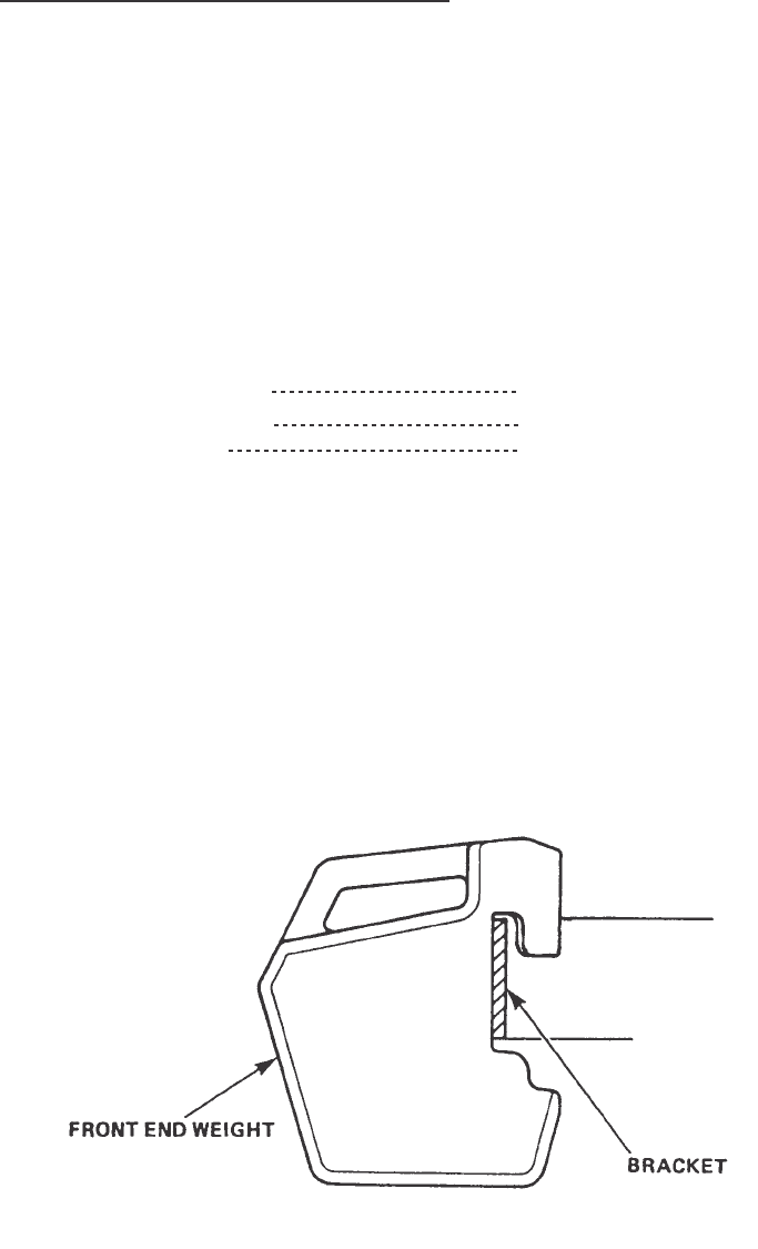
TIRES/WHEELS/SPACING/BALLAST
74
TRACTOR BALLAST
Ballast for your tractor includes front-end weights, rear wheel weights and
liquid ballast in the rear tires. Front-end weights improve the steering
characteristic when heavy hitch loads cause a movement of tractor weight
from the front to the rear wheels. Rear wheel weights and adding liquid to
the rear tires increase traction by putting weight on the driving wheels.
IMPORTANT: The Maximum operating weight of tractor should not exceed
the following values. The operating weight of tractor includes the weight of
tractor, ballast weight and implement.
Front Axle 1350kg (2977 lbs)
Rear Axle 1350kg (2977 lbs)
Total 2200kg (4851 lbs)
Front End Weights
Front-end weights can be mounted on the front-end bracket of the tractor
with locking bolts and nuts. The weights, locking bolts and nuts are available
from your Dealer. A maximum of six weights at 22 kg (49 lbs) each can be
installed, depending on implement application and soil conditions.
Use front-end weights as needed to provide effective steering control and
front end stability and to achieve maximum operating efficiency and tractor
filed performance. Refer to the weight table in this section for optional
methods of adding weight to the tractor.
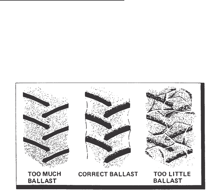
TIRES/WHEELS/SPACING/BALLAST
75
NOTE: When you have too much ballast installed on the tractor, you will
see the clear shape of the tire tread in the ground which is an indication of
no slippage. With too little ballast, the tire tread marks will not show because
of the tire slippage.
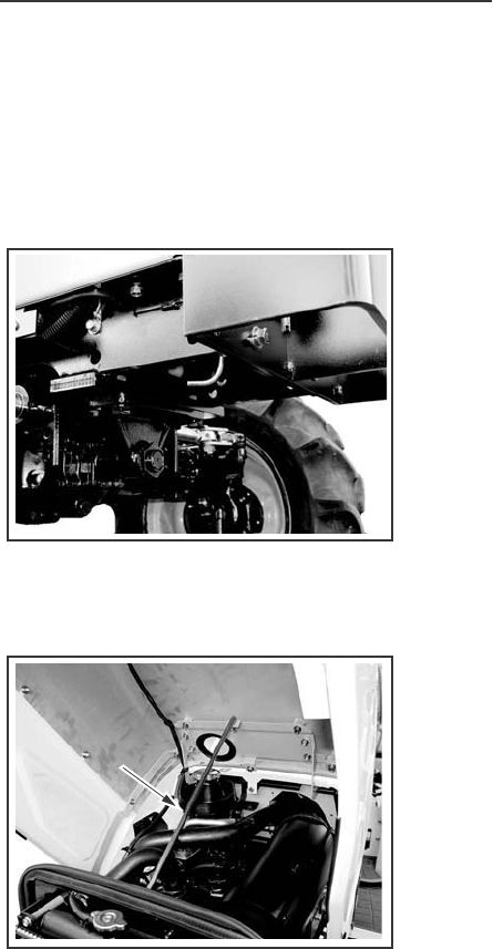
LUBRICATION/FILTERS/FLUIDS
76
HOOD
To do maintenance work on the engine lubrication system, cooling system,
fuel system and air induction system, you must life the tractor hood.
Pull the Lever release the hood.
Lift the hood, and insert the Support Rod into hole.
Remove both side covers.
STEP 1
STEP 2
BONNETBONNET
PROP ROD
PROP ROD
PROP ROD
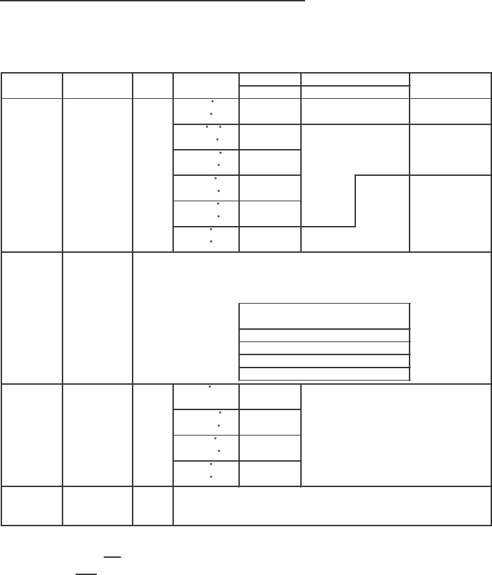
LUBRICATION/FILTERS/FLUIDS
77
Lubrication Table
NOTE: *-10W Cub Cadet Diesel Oil 737-3031
30 Cub Cadet Diesel Oil 737-3032
Grade
Single
-10 C
(14 F)
-20 -0 C
(-4-32 F)
-10-10 C
(14-50 F) 10W-
0-20 C 30
(32-68 F)
10-30 C
(50-86 F)
30 C
(86 F)
Size
1 Quart
5 Quarts
5 Gallons
55 Gallons
-0 C
(32 F)
-10-30 C
(14-86 C)
0-35 C
(32-95 F)
10 C
(50 F)
Description
(SEA No.)
Multi
Application Kind of oil
API
Classifi-
cation
Ambient
Temperature
5W-20
20W-40
Engine Engine Oil CC
CD
30*
40
5W
10W*
20W
20
Use High
Grade Diesel Oil
Cub Cadet
Engine Oil
737-3030A
Use high
Grade
737-3025
737-3026
737-3035
737-3027
Trans-
mission Oil
Use Cab Cadet
Hydraulic
Transmission
Fluid
Cub Cadet
Part No.
80W
85W
85W
Hydraulic
Transmission
Fluid
Gear
Lube
Front diff. Oil
Grease
Nipple Grease
Use Cub Cadet Muiti-
Purpose Grease 251H
14-1/2 oz. Cartridge 737-3034
GL-3
or
better
-
Use Cub Cadet
Gear Lube 5 qt.
737-3033
75W
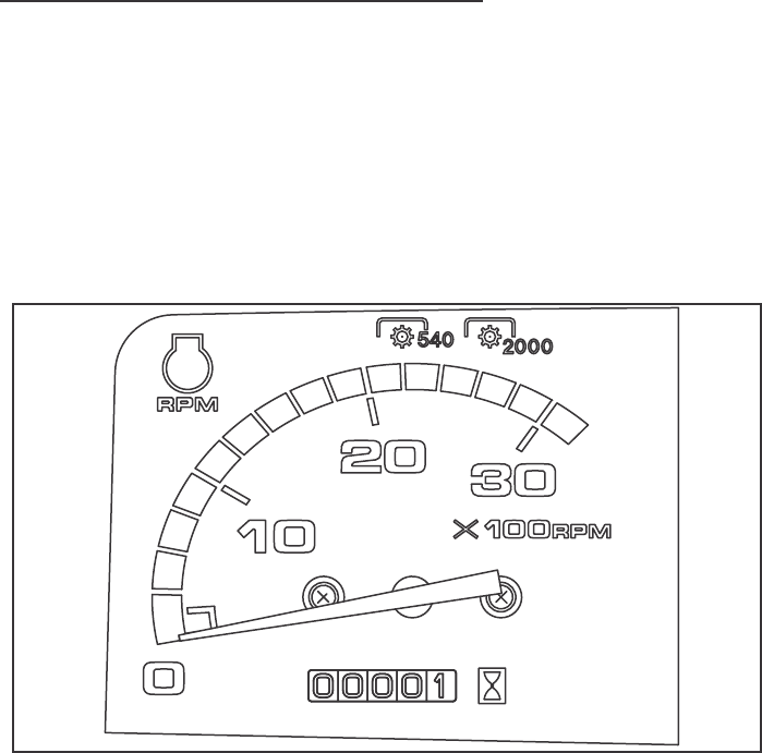
LUBRICATION/FILTERS/FLUIDS
78
SERVICE HOUR INTERVAL
Service your tractor at the intervals and locations given on the Lubrication
and Service Chart.
When you service your tractor, use only high quality lubricants.
Engine Hour meter
The engine hour meter shows the amount of actual hours of the tractor
has operated at an average RPM. The first number to the right displays
tenths of an hour and is a black number on a white surface. The remaining
numbers are white on black. Use the hour meter along with the Lubrication
Chart to service your tractor at the correct time periods.
[A] [B]

LUBRICATION/FILTERS/FRUIDS
79
Service After First 50 Hours
1. Engine Oil
Drain all the oil from the crankcase while the engine is warm and refill
with new oil to the upper Notch (full) on the engine oil dipstick. See
Engine Oil Change in this manual.
2. Engine Oil Filter
Replace the engine oil filter. See Engine Oil Filter in this manual.
3. Transmission & Hydraulic System.
(1) Transmission Oil
Check the level of the transmission oil. Add the specified fluid as
needed to maintain proper level. See Transmission Oil Level (Gear Drive)
or Transmission Oil Level (Hydrostatic Drive) in this manual.
(2) Hydrostatic Filter (Hydrostatic Drive)
Replace the filter with a new one. See Hydrostatic Filter in this manual.
(3) Hydraulic Filter
Replace filter with a new one. See Hydraulic filter in this manual.
4. Front Axle Lubricant (MFD)
Change the oil. See FRONT AXLE LUBRICATION (MFD) in this manual.
5. Radiator Core
Inspect the radiator core and clean if necessary. See COOLING
SYSTEM in this manual.
6. Hoses and Connections between Air Cleaner and Manifold.
Inspect for loose fit or leakage. See AIR INDUCTION SYSTEM in
this manual.
7. Water Pump, Fan and Alternator Belt Tension.
Check the belt for tension, replace if necessary. See Fan Belt Adjustment
in this manual.

LUBRICATION/FILTERS/FLUIDS
80
SYSTEM U.S.
MEASURE
METRIC
MEASURE
IMPERIAL
MEASURE
Engine Oil
Filter change 4.7 QTS 4.5 Litres 4.0 QTS
with filter change 5.3 QTS 5.0 Litres 4.4 QTS
Fuel tank 7.1 Gallons 27 Litres 5.9 Gallons
Coolant
Engine and radiator 5.8 QTS 5.5 Litres 4.9 QTS
coolant bottle 0.4 QTS 0.4 Litres 0.4 QTS
Transmission Oil
gear drive 31.7 QTS 30 Litres 26.4 QTS
hydrostatic drive 32.7 QTS 31 Litres 27.3 QTS
Front Axle
MFD 4.2 QTS 4.0 Litres 3.5 QTS
SYSTEM CAPACITIES

LUBRICATION/FILTERS/FLUIDS
81
MARK Y: Yearly or 1000 Hours, Whichever occur first.
AY:Yearly or as needed.
Note 1: Consult your Dealer.
Note 2: Replace element after 10 cleanings or yearly.
Note 3: Apply Gear Oil.
C
L
E
A
N
C
H
A
N
G
E
C
H
E
C
K
G
R
E
A
S
E
D
R
A
I
N
Engine Oil Level 110
Front Axle Tie Rod 210
Front Axle Pivot Pin 110
Popwer Steering Cyllinder End 10
Brake Pedal Boss 210
Transmission Oil Level 110
Radiator Coolant Level 110
Fuel Fillter Cup 110 10
Air Cleaner 110 10
Fan Belt Tension 110
Grill and Radiator Area 150 50
Tire Pressure 450
Fuel Tank Water Drain Plug 150
Engine Oil 1100
Wheel Retaining Bolts and Nuts 100
Engine Oil Filter 1200
Transmission Oil 1200
Hydroustaic Filter (Hydrostatic Drive)
1200
Hydraulic Filter 1200
MFD-Front Axle Lubricant 1200
Clutch Pedal 1200
Brake Pedal 2200
Air Induction Systems 1200
Engine Valve Clearance (See Note 1)
b200
ROPS Equlment 200
Cooling System YY Y
Air Cleaner Filter Element (See Note 2)
1AY
All Linkage Pivot Points (See Note 3)
8AY
Threads of 3-Point Hitch Links 2AY
Fuel Filter 1AY
Hydraulic System AY
Battery Water Level and terminals AY AY
N
O
.
O
F
.
P
O
I
N
T
S
FREQUENCY IN HOURS
SERVICE POINT
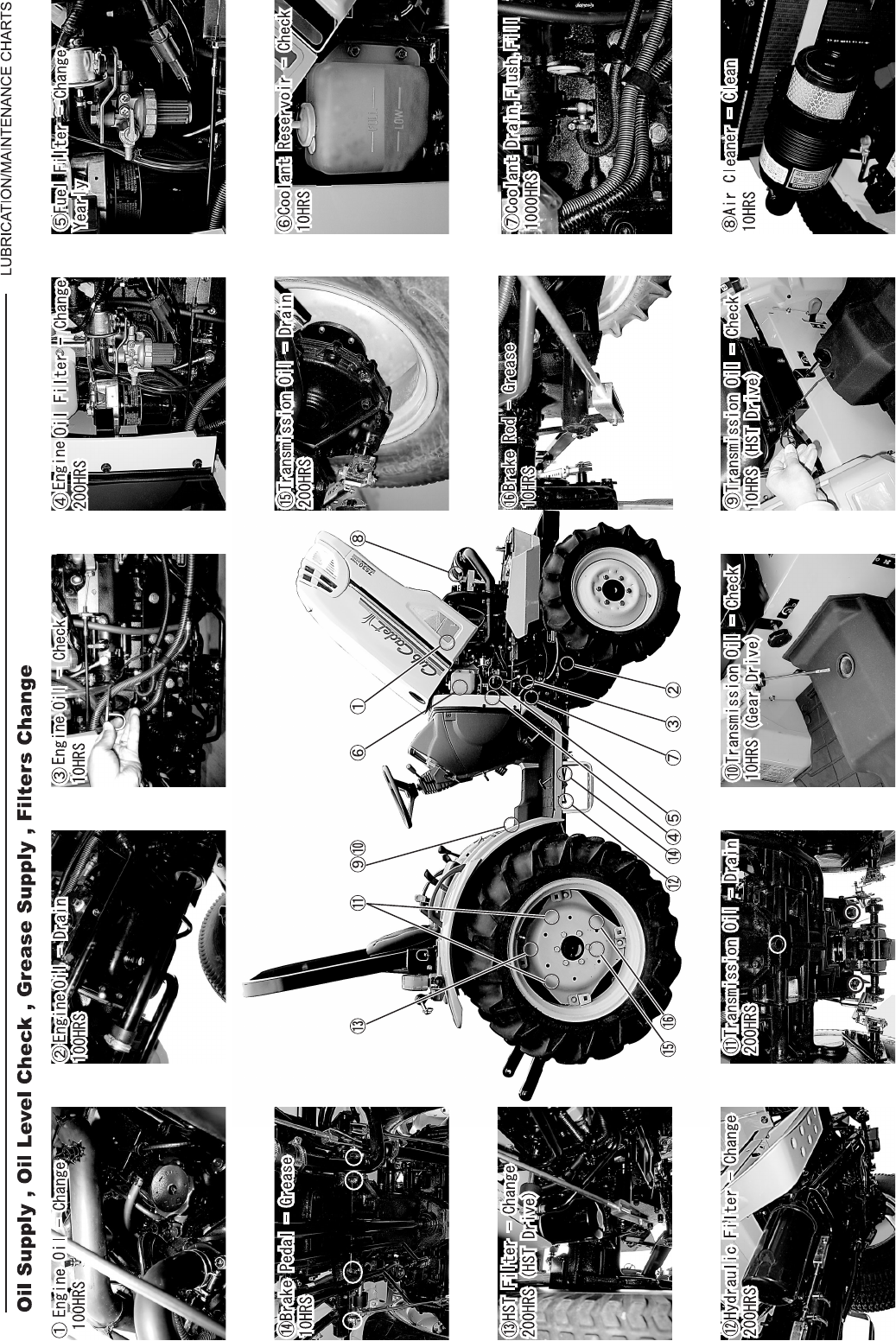
82
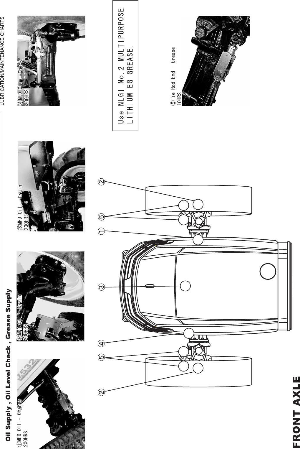
83
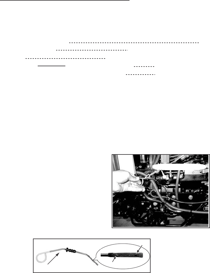
LUBRICATION/FILTERS/FRUIDS
84
ENGINE LUBRICATION
Service Specifications
Oil Level Check Interval Daily
Oil Change Interval Every 100 hours (See NOTE)
Oil Type See Lubrication Table in this manual.
Oil Capacity Without Filter Change 4.5 Liters (4.7 QTS)
With Filter Change 5.0 Liters (5.3 QTS)
NOTE: Change the engine oil after the first 50 hours of operation and
then use the regular change interval. Change the engine oil more frequently
when the operating conditions are severe, such as, operating in very high
or very low ambient temperatures.
Engine Oil Level
To check the engine oil level, put the
tractor on level ground and stop the
engine. Pull the dipstick out, wipe the
dipstick with a dry cloth and install
the dipstick to check the oil level.
If the oil level is below the A (Add)
mark, add oil to raise the oil level to
the F (Full) mark.
Do not raise the oil level above the
F (Full) mark.
IMPORTANT: The level should be checked before starting or 5 minutes
after the engine has been shut off.
NOTE: Above illustrations are in case of 7530/7532.
ENGINE OIL DIPSTICK
ENGINE OIL DIPSTICK FULL MARK
FULL MARK
FULL MARK
ADD MARKADD MARK
ADD MARK
ADD MARK
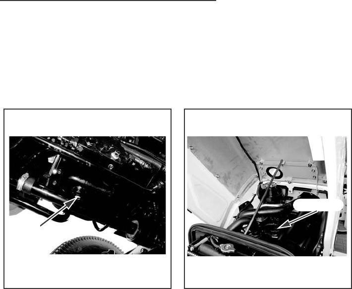
LUBRICATION/FILTERS/FRUIDS
85
Engine Oil Change
To change the engine oil, put the tractor on level ground and stop the engine.
Change the engine oil as follows:
NOTE: For best results change the oil while the engine is still warm.
1. Remove the oil pan drain plug and drain the oil from the engine.
2. See Engine Oil Filter in this manual, if the filter is to be changed.
3. Install the drain plug in the oil pan. Tighten the plug to a torque of 50
to 60 Nm (36 to 43 lb ft).
4. Put the correct type and amount of new oil into the engine. See
Engine Oil Selection in this manual for recommended oil type.
IMPORTANT: Do not use the oil level dipstick as a guide when you fill
the engine crankcase with oil. Always measure the amount of oil you install.
5. Start the engine and run for five minutes at 1200 rpm.
Check for oil leaks at the filter base and drain plug.
6. Stop the engine. Wait approximately five minutes for the oil to return
to the oil pan. Check the oil level on the dipstick and add oil if needed.
DRAIN PLUG
OIL FILL CAP
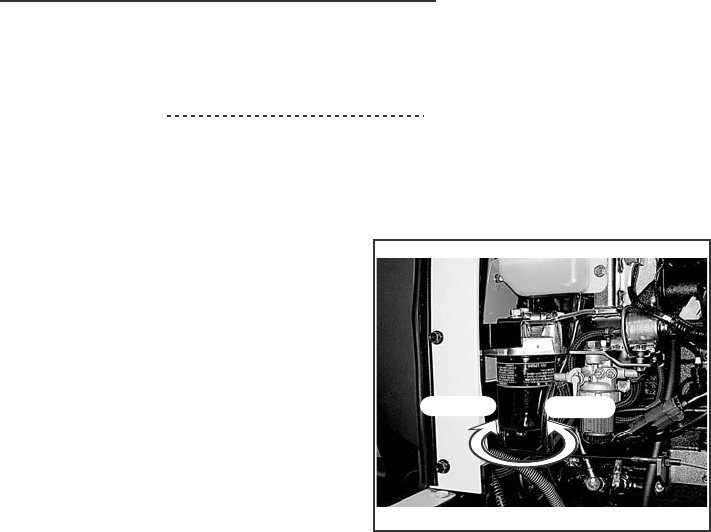
LUBRICATION/FILTERS/FRUIDS
86
Engine Oil Filter
Change Interval Every 200 hours (See NOTE)
NOTE: Change the engine oil filter after the first 50 hours of operation
and then use the regular change interval.
IMPORTANT: Change the oil filter
at the recommended time interval.
Your Dealer has approved genuine
filters. Do not use other type filters.
Change the engine oil filter as follows:
1. Drain the oil from the engine.
See Engine Oil Change in this
manual.
2. Turn the oil filter counterclockwise
to remove. Use a filter wrench,
if necessary.
3. Apply clean oil to the O-ring on the new filter.
4. Install the filter. Turn the filter until the O-ring comes in contact with the
case surface. Tighten the filter an additional 2/3 turns by hand.
IMPORTANT: DO NOT use a filter wrench to install the oil filter. When
the filter is too tight, you can cause damage to the O-ring and filter.
5. Put new oil in the engine. See Engine Oil change in this manual.
INSTALL
REMOVE
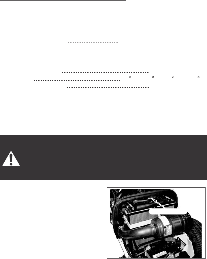
LUBRICATION/FILTERS/FRUIDS
87
COOLING SYSTEM
Service Specifications
Coolant Change Interval Every 1000 hours or once each
year whichever occurs first.
Capacity of System
Engine and Radiator 5.5 Liters (5.8 QTS)
Coolant bottle 0.4 Liters (0.4 QTS)
Thermostat 82 C to 95 C (180 C to 203 F)
Radiator Cap Pressure 88.2 kPa (12.8 PSI)
Daily before starting the engine, check the coolant level the coolant reserve
bottle. The coolant level should be between the "FULL" and "LOW" lines
when the engine is cool.
Pressure Cooling System
Check and service cooling system according to maintenance
instructions. Hot coolant can spray out if radiator cap is removing
while system is hot. To remove radiator cap, let system cool, turn
to first notch, and then wait until all pressure is released. Scalding
can result from fast removal of radiator cap.
1. The pressure cap on a pressure
cooling system has a control valve
that operates as a SAFETY RELIEF
VALVE to keep the pressure within
the system operating range.
Operating the engine without a
pressure cap or with a pressure cap
that has a control valve that is not
set to operate at the correct
pressure can cause damage.
2. A pressure cooling system decreases the loss of coolant caused by
evaporation or boiling. The system must have good seals at the radiator
cap, hoses and hose connections. It is important that you stop ALL
LEAKS OF ANY SIZE as soon as the leaks are found. A small leak can
become a large flow when pressure is increased in the cooling system.
While the tractor is in operation, a weak hose can break and cause injury
or damage. Check all hoses and hose connections with frequency. KEEP
HOSES, HOSE CONNECTIONS AND PRESSURE CAP IN GOOD
CONDITION.
PRESSURE CAP

LUBRICATION/FILTERS/FRUIDS
88
Coolant Solutions
Your tractor cooling system is equipped with an ethylene glycol coolant
solution that has a high boiling point.
IMPORTANT: Change the coolant solution at the change interval
recommended in this manual (See Lubrication and service Chart). The heat
generated by the diesel engine causes a natural change in the inhibitors in the
coolant, which results in loss of corrosion protection. The loss of the inhibitors
may cause water pump cavitations and cylinder block erosion.
Install only ethylene glycol coolant solution in the cooling system. Use a
good quality, high boiling point, ethylene glycol that does not have any
additives to stop leaks. Do not install any rust inhibitors that are not approved.
It is possible that the rust inhibitors and ethylene glycol will not mix and
work against each other to decrease corrosion protection, form deposits
in the cooling system and cause damage to the cooling system and
the radiator.
Do not use a low boiling point, alcohol type coolant solution.
The boiling point of alcohol is below the tractor minimum operating
temperature; loss of coolant due to evaporation will result.
IMPORTANT: Always have a minimum of 50 percent ethylene glycol
coolant in the cooling system at all times and at all ambient temperature
ranges. Do not install more than 50 percent ethylene glycol in the cooling
system unless the ambient air temperature will be less than -37 C (-34 F)
More than 50 percent ethylene glycol decreases heat transfer and will cause
the engine surface temperature to be higher than normal.
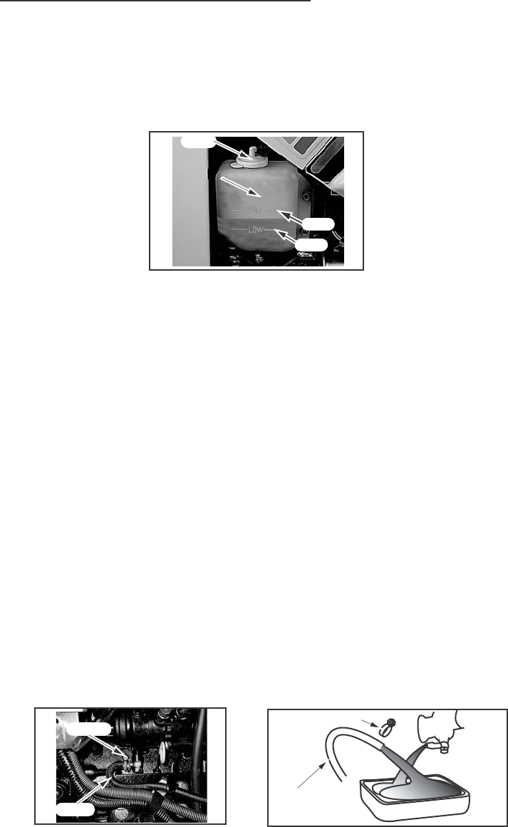
LUBRICATION/FILTERS/FRUIDS
89
Cleaning The Cooling System
IMPORTANT: NEVER PUT COOLANT IN A HOT ENGINE: THE ENGINE
BLOCK OR CYLINDER HEADS CAN GET CRACKS BECAUSE OF THE
DIFFERENCE IN TEMPERATURE BETWEEN THE METAL AND THE COOLANT.
Clean the cooling system each time the coolant is changed. See the
Lubrication and Service Chart in this manual for recommended change
intervals. Clean the system as follows:
1. Remove the hose from to drain the coolant. Close the plug after the
system is empty.
2. Install a good type of radiator cleaner and fill the system with clean water.
Follow the instructions given with the radiator cleaner.
3. Remove the radiator cleaner solution. Flush the system with clean water.
4. Fill the cooling system with the coolant solution specified in this manual.
Install coolant system treatment (If required). See Coolant Solutions
in this manual for more information.
5. Check the hoses, radiator, pump and water manifold for leaks.
IMPORTANT: Never drain the coolant when the engine is hot.
NOTE: After the cooling system is completely filled, run the engine for
approximately five minutes to remove all air from the system. Check the
coolant level and add coolant if needed.
CAP
COOLANT
RECOVERY
RECOVERY
RESERVOIR
RESERVOIR
COOLANT
RECOVERY
RESERVOIR
FULL
LOW
CLUMP
HOSE
HOSE
CLUMP
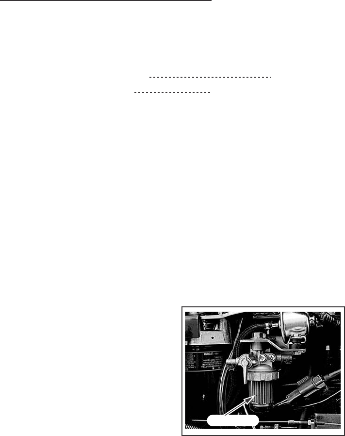
LUBRICATION/FILTERS/FRUIDS
90
FUEL SYSTEM
Service Specifications
Fuel Filter Cup Service Interval Every 10 Hours
Fuel Filter Element Change Replace when loss of
power or misfiring occurs
This type filter cannot be cleaned. Change the filter when the engine is
misfiring or a loss of power is evident. It is necessary to remove the air
from the system after each replacement.
Only a filter recommended by your Dealer should be used, to be sure
that it is both effective and capable of withstanding the required suction or
pressure without damage to the filter element.
Fill the fuel tank at the end of each day to reduce condensation.
NOTE: Do not fill the fuel tank to its full capacity. Space is required for
vapor expansion in the event of a temperature change. A tank filled to
capacity may overflow if exposed to a rise in temperature or direct sunlight.
Water Removal from the Filter Cup
Before starting each day's work,
check for water or sediment in the
filter cup. If water or sediment is in
the cup, close the fuel shut-off valve,
remove filter cup, clean and reinstall.
NOTE: Be careful not to allow dirt,
water and other foreign materials to
get into the filter when cleaning the cup. FILTER CUP

LUBRICATION/FILTERS/FRUIDS
91
Diesel Fuel Specifications
Use a good grade of Number Two Diesel Fuel in your Diesel Engine. Do not
use other types or fuel. The use of other fuels will result in loss of engine
power and high fuel consumption.
NOTE: When the temperature is very cold, the use of a mixture of Number
one and number Two Diesel Fuel is permitted for a short period of time.
See your fuel Dealer for winter fuel requirements in your area.
Specifications For Acceptable
Number Two Diesel Fuel
A.P.I. Gravity (Min) 34
Flash Point, (Min) 60 C (140 F)
Cloud Point (Wax Appearance Point) (Max) - 21 C(-5 F)
Pour Point, (Max) - 26 C (-15 F)
Distillation Temperature, 90% Point 282 to 338 C
(540 to 640 F)
Viscosity, at 38 C (100 F)
Centistokes 2.0 to 4.3
Saybolt seconds Universal 32 to 40
Cetane Number (Min) 43 (45 to 55 for
winter or high
altitudes)
Water and Sediment By Volume (Max) 0.05 of 1%
Sulfur, by weight (Max) 0.50 of 1%
Copper Strip Corrosion (Max) No.2
Ash, By Weight (Max) 0.01 of 1%
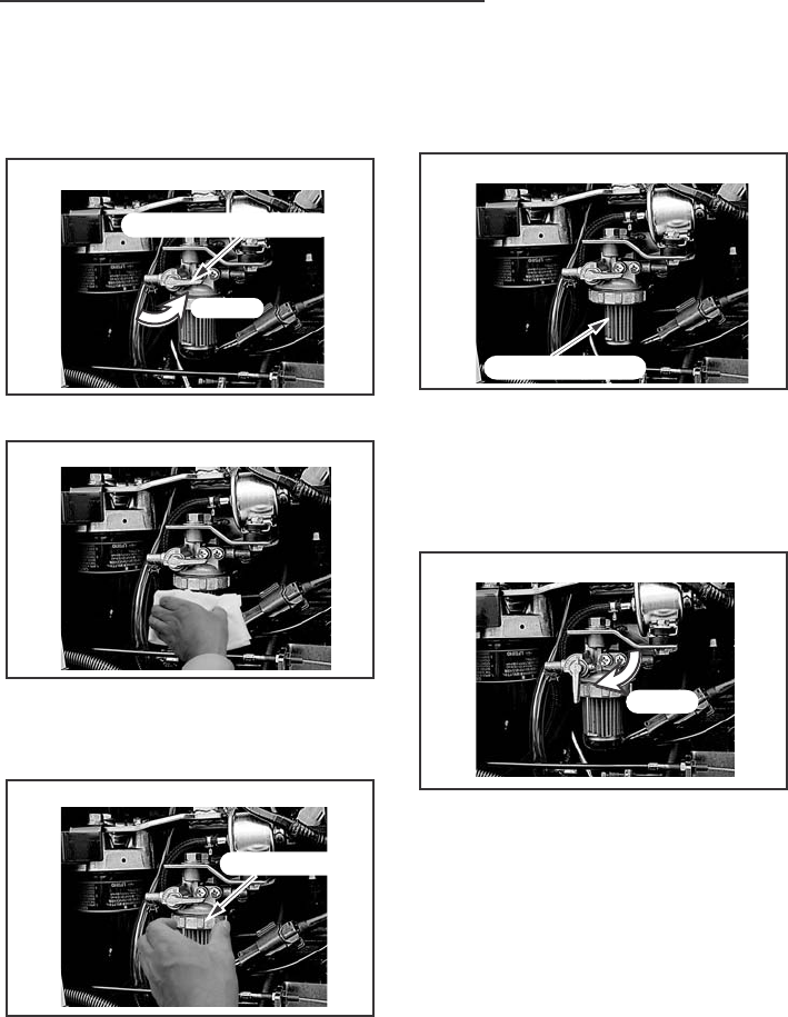
LUBRICATION/FILTERS/FRUIDS
92
Fuel Filter Element Replacement
To replace the filter element, use following procedure:
Close the fuel shut-off valve. Install new filter element. Assemble
filter cup and retaining nut to filter body.
Clean the outside of the filter body
and cup to prevent dirt or foreign
materials from entering the system.
Loosen the filter cup-retaining nut.
Remove filter cup. Remove old filter
element and clean inside of filter cup.
NOTE: Be sure O-ring is in place on
the filter body and filter cup.
Open the fuel shut-off valve and vent
the fuel system. See Fuel System
Air removal in this manual.
STEP 6
Clean fuel off the engine. Start the
engine to check for fuel leaks around
the filter, lines and fittings.
NOTE: If the engine does not have
power with a full load after you have
done the filter service and removed
the air from the system, see your Dealer
to find and correct the cause.
STEP 1
STEP 5
STEP 4
STEP 3
STEP 2
FUEL SHUT-OFF VALVE
CLOSE
RETAINING NUT
FILTER ELEMENT
OPEN
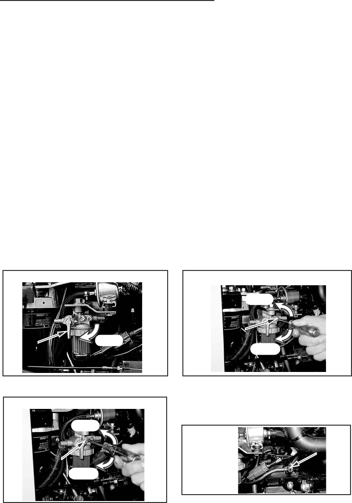
LUBRICATION/FILTERS/FRUIDS
93
Fuel System Air Removal
AIR MUST BE REMOVED FROM THE FUEL SYSTEM.
AIR CAN ENTER THE FUEL SYSTEM WHEN:
1. An engine stopped from lack of fuel.
2. The fuel filter has been replaced or the filter cup has been cleaned.
3. Any connections between the injection pump and fuel tank have been
loosened or disconnected for any reason.
4. The tractor has not been operated of time.
5. The fuel pump has not operated correctly.
NOTE: If the tractor has not completely run out of fuel, it is possible to put
fuel in the tank and start the engine without doing the air removal procedure,
but a small amount of air can be in the filters. Air in the system will cause
loss of power and stall the engine when a load is applied.
To remove air from the fuel system, turn off the engine and use the
following procedures:
Open the fuel shut-off valve. Loosen the No.2 air vent screw until
the fuel flowing is free of air bubbles.
Tighten the No.2 air vent screw.
Loosen the No.1 air vent screw on
the fuel filter until the fuel flowing
from the fuel filter is free of air bubbles.
Tighten the No.1 air vent screw.
Loosen the air vent bolt on the
injection pump and turn the key switch
"ON" position until the fuel flowing
from the pump is free of air bubbles.
Tighten the air vent bolt.
STEP 1 STEP 3
STEP 2
STEP 4
FUEL
FUEL
SHUT-OFF
SHUT-OFF
VALVE
VALVE
FUEL
SHUT-OFF
VALVE
OPEN
AIR VENT BOLT
AIR VENT BOLT
AIR VENT BOLT
OPEN
CLOSE
NO.2 AIR VENT
NO.2 AIR VENT
SCREW
NO.2 AIR VENT
SCREW
OPEN
CLOSE
NO.1 AIR VENT
NO.1 AIR VENT
SCREW
NO.1 AIR VENT
SCREW
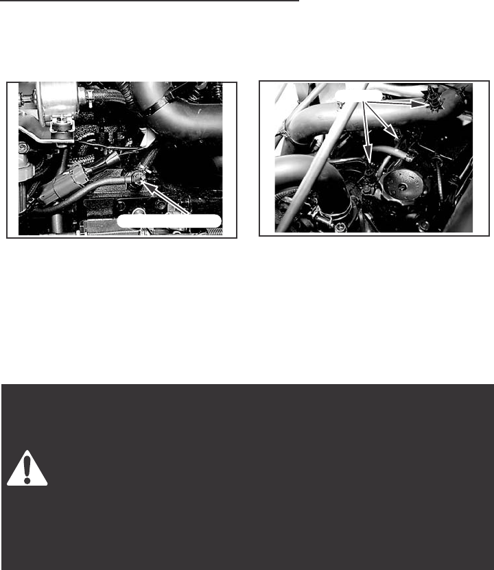
LUBRICATION/FILTERS/FRUIDS
94
Fuel Injection Pump and Nozzle Check
The fuel injection pump and nozzles are precision units and must be
serviced only by your dealer.
The injection pump is correctly set and sealed at the factory and should
not require an adjustment. Whenever adjustment or repairs are necessary,
see your dealer. Do not tamper with any of the pump units.
Hydraulic oil or diesel fuel leaking under pressure can penetrate
the skin and cause injection or other injury.
To Prevent Personal Injury:
Relieve all pressure, before disconnecting fluid lines.
Before applying pressure, make sure all connections are tight and
components are in good condition.
Never use your hand to check for suspected leaks under pressure.
Use a piece of cardboard or wood for this purpose.
If injured by leaking fluid, see your doctor immediately.
INJECTION PUMP
INJECTION PUMP
INJECTION PUMP
NOZZLE
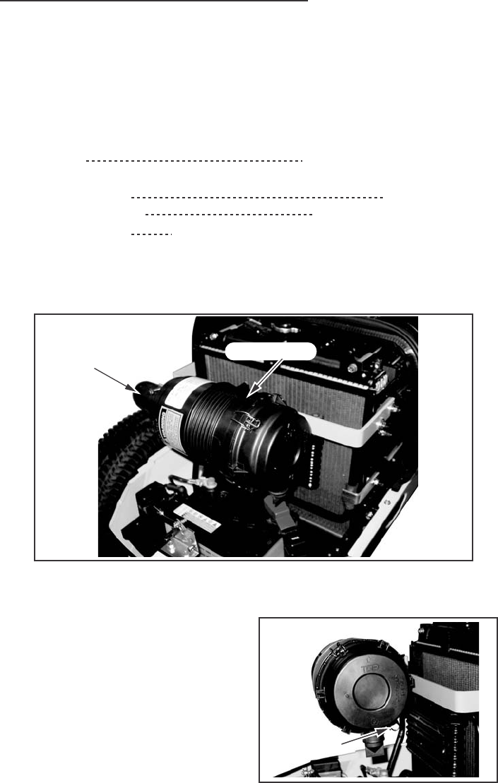
LUBRICATION/FILTERS/FRUIDS
95
AIR INDUCTION SYSTEM
The air induction system components require service at different intervals
according to local operating conditions.
Service Specifications
Dump Valve Clean daily or every 10 hours
Filter Element
Clean Element When necessary
Replace Element After 10 cleanings or yearly
System Inspection Every 200 hours or yearly whichever occurs first
Your tractor is equipped with a dry-type air cleaner with a replaceable
element.
IMPORTANT: Service the air induction system at the given service intervals.
Correct maintenance will add to the life of the engine. Keep all connections
on the outlet hose tight.
Dump Valve
The dust in a filter case should be
dumped daily using the dump valve
when operating in extremely dusty
conditions.
INLET HOSE AIR CLEANER
DUMP VALVE
DUMP VALVE
DUMP VALVE
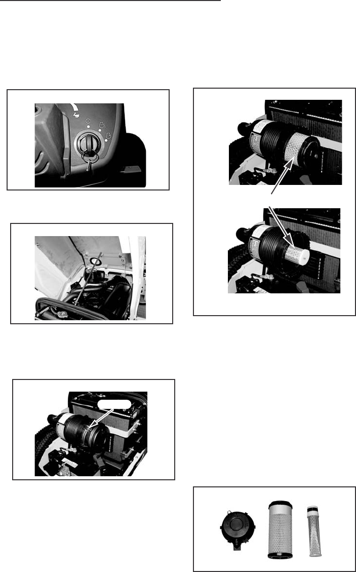
LUBRICATION/FILTERS/FRUIDS
96
Air Filter Element Removal
Avoid over servicing the air filter element. The filter element should be
removed for cleaning only when restriction causes a power loss.
Stop the engine
Lift the hood and connect the hood
support rod.
When servicing the air filter element,
remove clamp and remove element
by pulling it straight out very slowly
and carefully. Clean interior of canister.
After replacing the new or cleaned
element, install and tighten the
wing bolt.
NOTE: Never attempt to remove the
element from the air cleaner while the
engine is running.
When installing the element, inspect
the element gasket. If the gasket or
element surface is damaged, replace
the element immediately.
STEP 1
STEP 2
STEP 3
STEP 4
OUTER
INNER
CLAMP
ELEMENT
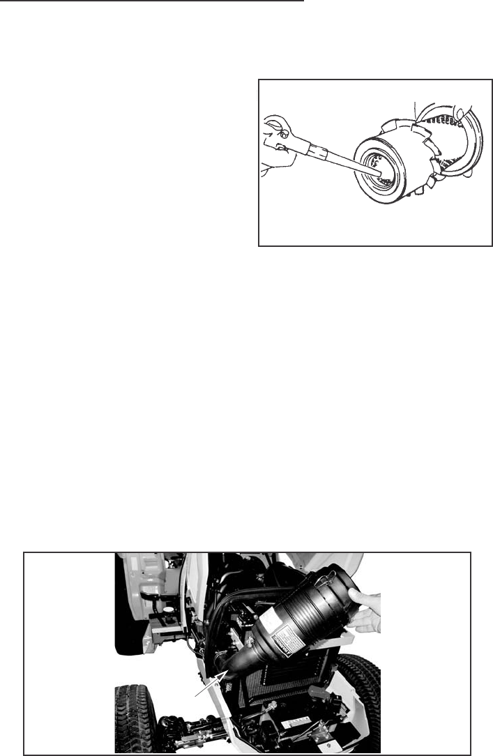
LUBRICATION/FILTERS/FRUIDS
97
Element Cleaning
Use clean, dry compressed air up
and down the pleats on the clean
side (inside) of the element.
Continue this until the element is clean.
NOTE:
1. The paper element must be
handled with care. Do not hit the
element against a hard surface.
2. Air pressure at the nozzle must not exceed 689 kPa (100 PSI).
3. It may be necessary to replace the element sooner if the time interval
between servicing becomes short indicating the element does not
respond to cleaning (soot contaminated).
System Inspection
Check the dump valve and the all hoses for cracks and wear. Replace if
needed. All the connections on the hoses must be tight. All the gaskets
must be in good condition and the bolts must be drawn up tight.
NOTE: Inspect the hoses and connections after the first 50 hours of
operation and replace when necessary.
DUMP
VALVE
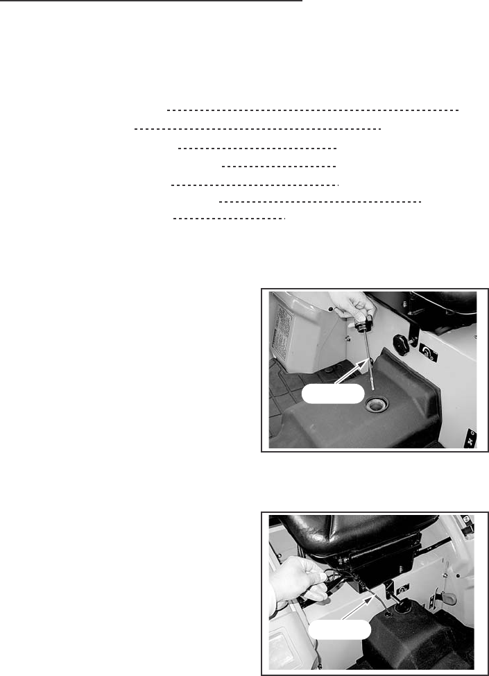
LUBRICATION/FILTERS/FRUIDS
98
TRANSMISSION & HYDRAULIC LUBRICATION
Service Specifications
Oil Level Check Interval Daily
Oil Change Interval Every 200 hours.
Oil Capacity - Gear Drive 28 Liters (29.6 Quarts).
Hydrostatic Drive 31 Liters (32.7 Quarts).
Oil Type - Gear Drive STOU OIL or TOU OIL
Hydrostatic Drive STOU OIL
Hydraulic System Check Yearly inspect for leaks, cracks
and abrasion. Tighten fittings or
replace as needed.
Transmission Oil Level
(Gear Drive)
To check the transmission fluid level,
put the tractor on level ground.
Unscrew the filler cap with dipstick
and wipe it clean. Check level - Do
not screw in cap when checking. If the
fluid level is below the lower line of
the dipstick, add the recommended
fluid to raise the fluid level to the
F (Full) marked position.
Transmission Oil Level
(Hydrostatic Drive)
Before checking the oil level of the
hydrostatic drive tractor, run the engine
for three to five minutes at 1500 RPM
with the speed ratio control lever,
range shift lever and PTO control lever
in Neutral or OFF position. Then check
the oil level in the transmission.
To check the transmission oil level, put the tractor on level ground.
Check the oil level on the transmission dipstick. If the oil level is below the
lower line of the dipstick, add the recommended oil to the transmission to
raise the oil level to the F (Full) marked position.
DIP STICK
DIP STICK
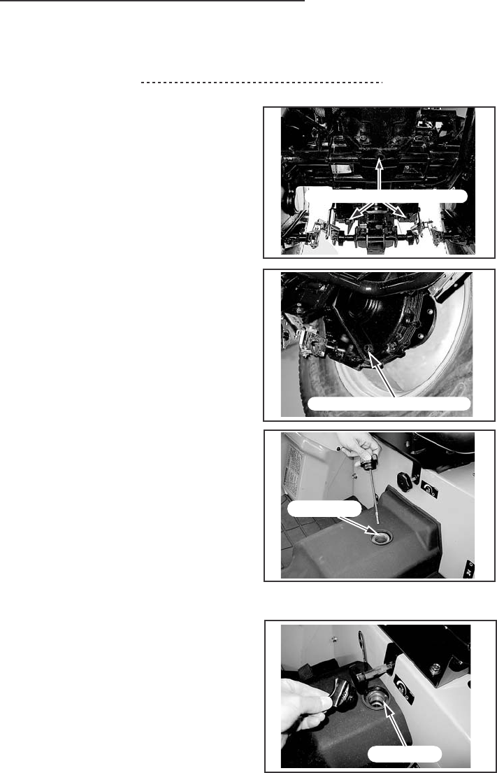
LUBRICATION/FILTERS/FRUIDS
99
Transmission Oil Change
Oil Change Interval Every 200 hours
To change the transmission oil, use
the following procedure:
1. Put the tractor on level ground,
apply the park brake and stop the
engine. Move the range shift lever
to L position.
2. Remove the drain plugs from the
transmission case. (5 )
NOTE: For best results, drain the oil
when the oil is warm.
3. Replace the hydraulic filter. See
Hydraulic Filter in this manual.
4. For the hydrostatic drive tractor,
replace hydrostatic filter, See
Hydrostatic Filter (Hydrostatic Drive)
in this manual.
5. Install the drain plugs with a seal
washer and tighten to a torque of
39 to 44 Nm (29 to 33 lb ft).
6. Add the recommended oil through
the fill hole and check the oil level.
7. Start the engine and check for
leaks.
8. Recheck the oil level after stopping
the engine. If the oil level is low,
add oil up to the specified level.
GEAR DRIVE
HYDROSTATIC DRIVE
FILL HOLE
TRANSMISSION DRAIN PLUG
TRANSMISSION DRAIN PLUG
FILL HOLE
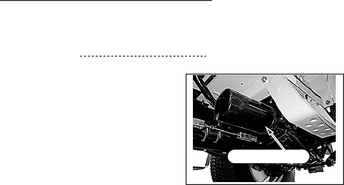
LUBRICATION/FILTERS/FRUIDS
100
Hydraulic Filter (Gear & Hydrostatic Drive)
Change Interval Every 200 hours (See NOTE)
NOTE: Replace the hydraulic filter
after the first 50 hours of operation
and every 200 hours of operation
thereafter. Your Dealer has approved
genuine filters. Do not use other type
filters.
CHANGE THE HYDRAULIC FILTER AS FOLLOWS:
1. Put the tractor on level ground, move the range shift lever to the L
position and apply the park brake.
2. Put an oil canister under the hydraulic filter.
3. Turn the filter counterclockwise to remove. Use a filter wrench if
necessary.
4. Apply clean oil to the O-ring on the new filter.
5. Install the filter. Turn the filter until the O-ring comes in contact with the
case surface. Tighten the filter an additional 2/3 turns by hand.
IMPORTANT: DO NOT use a filter wrench to install the hydraulic filter.
When the filter is too tight, you can cause damage to the O-ring and filter.
6. Wipe around the hydraulic filter with a dry cloth.
7. Change the transmission oil. See Transmission Oil Change in this
manual.
HYDRAULIC FILTER
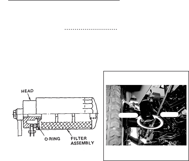
LUBRICATION/FILTERS/FRUIDS
101
Hydrostatic System Filter (Hydrostatic Drive)
Filter Change Interval Every 200 hours (See NOTE)
NOTE: Change the filter after the first 50 hours of operation and every 200
hours of operation thereafter. Replace the filter more frequently when
operating under unusual dirt and dust conditions. Your Dealer has approved
genuine filters. Do not use other type filters.
When the transmission fluid filter needs changing, change the filter as
follows:
1. Drain the transmission oil. See Transmission Oil Change in this manual.
2. Remove the hydrostatic system filter by turning it counterclockwise.
Use a filter wrench, if necessary.
3. Apply clean oil to the O-ring on the new filter.
4. Install the new filter. Turn the filter clockwise until the O-ring comes in
contact with the filter head surface. Tighten the filter an additional 2/3
turns by hand.
5. Add the transmission oil through the fill port and check the oil level.
6. Run the engine and check for leaks.
7. After stopping the engine, check the oil level. If it is low, add clean oil.
HYDROSTATIC
HYDROSTATIC
SYSTEM
SYSTEM
FILTER
FILTER
HYDROSTATIC
SYSTEM
FILTER
INSTALL
REMOVE
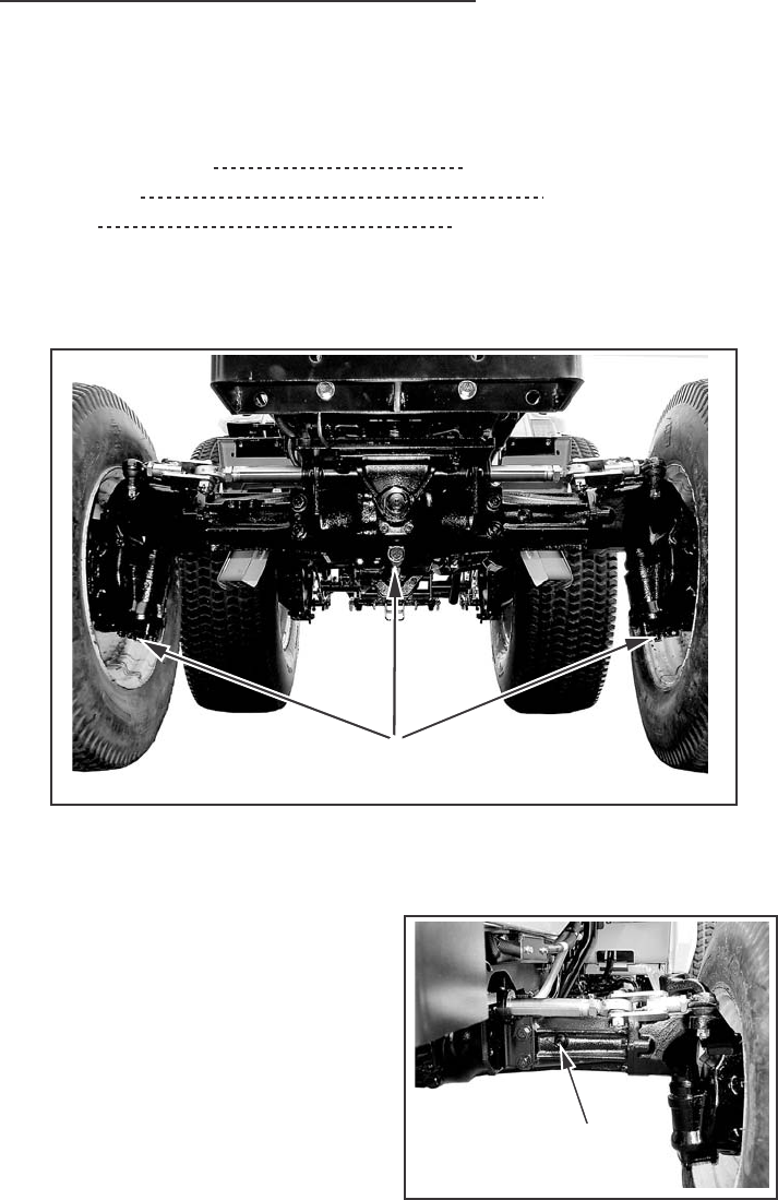
LUBRICATION/FILTERS/FRUIDS
102
FRONT AXLE LUBRICATION (MFD)
Service Specifications
Oil Change Interval Every 200 hours (See NOTE)
Oil Capacity 4.0 Liters (4.2 Quarts)
Oil Type SAE 85W-140 Gear Lubricant
NOTE: Change the oil after the first 50 hours of operation and then every
200 hours of operation.
Front Axle Oil Level
To check the front axle oil level, put
the tractor on level ground. Remove
the oil level plugs located on the rear
of the both gear cases. If the oil level
is low, add the recommended oil type
through the fill hole located on the RH
side of axle housing until the oil
begins to flow out of the level plug
holes. OIL LEVEL PLUG
DRAIN PLUG
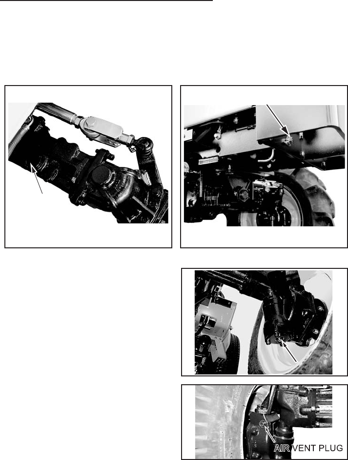
LUBRICATION/FILTERS/FRUIDS
103
Front Axle Oil Change
1. To change the front axle oil, put the tractor on level ground. Put the
range lever in L, engage the park brake and stop the engine.
2. Remove the fill cap located on
the axle housing, the differential
drain plug located in the bottom
of the housing and the gear case
drain plugs located on the bottom
of both side gear cases to drain
the oil.
NOTE: For best results, drain the oil
when the oil is warm.
3. Install the differential and both gear cases drain plugs. Remove the oil
level plugs located on both gear cases. Remove both Air Vent Plug
located on both GearCases. Supply oil through the Fill Hole.
Supply multipurpose sulfur-phosphorous type gear lube until the oil
flows out of the Air Vent Plug Hole, and install Air Vent Plug.
Until the oil flows out of the Level Plug Hole. Add the recommended
oil through the fill hole until the oil begins to flow out the level plugholes.
Install the oil level plugs and the fill cap.
FILL HOLE
DIFFERENTIAL DRAIN PLUG
DRAIN PLUG
DRAIN PLUG
DRAIN PLUG
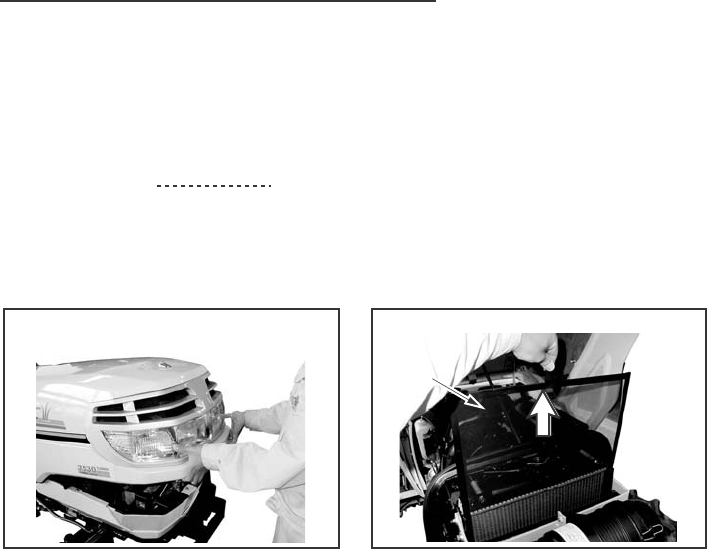
MAINTENANCE/ADJUSTMENTS
104
COOLING SYSTEM
Grille Screens and Radiator Area
Grille Screens and Radiator Area
Service Interval Every 50 hours or more frequently if required.
To clean the radiator screen, put the tractor on level ground, apply the park
brake and stop the engine.
STEP3
Clean the radiator screen and the
surrounding area.
STEP4
Install the radiator screen.
Lower the hood.
Lift and Lock the hood. Lift the radiator screen.
STEP 1 STEP 2
RADIATOR
SCREEN
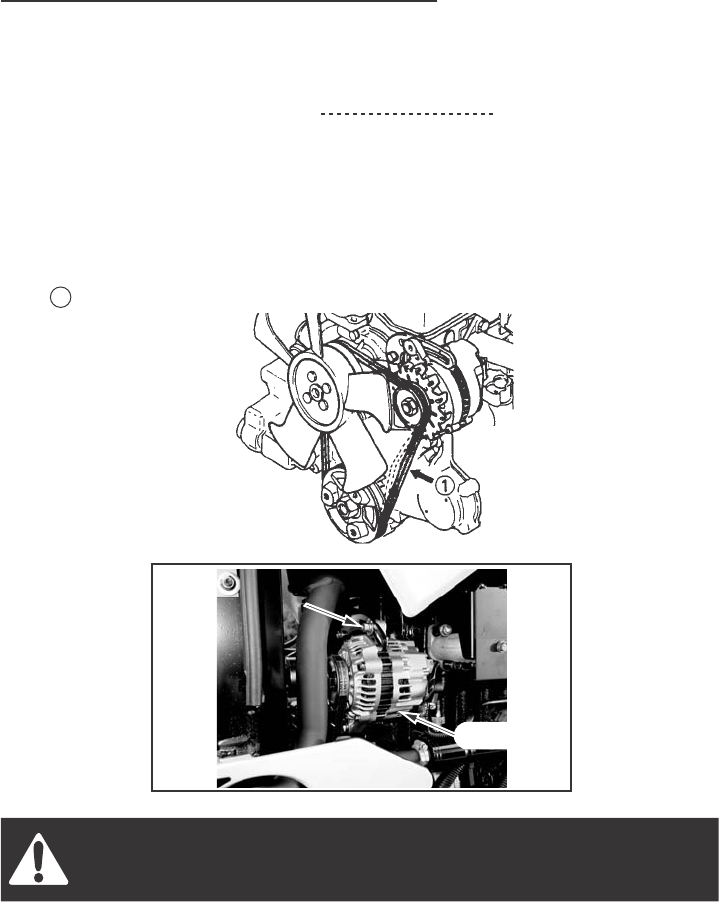
MAINTENANCE/ADJUSTMENTS
105
Fan Belt Adjustment
Fan Belt Tension Check Interval Daily or after 10 Hours
NOTE: Adjust the belt tension after the first 50 hours of operation and
replace when necessary.
Measure the fan belt for correct tension. Check to see if the belt deflection
is about 13mm (0.5 inch) when pushing the belt with 10 kg (22 lb) load at
point 1 .
Rotating fan and belts. Contact can injure. Keep clear.
To Adjust the fan belt tension loosen the adjusting bolt and pivot nut of the
alternator. Move the alternator away from the engine until correct belt tension
is reached. Tighten the adjusting bolt and pivot nut to a torque of 16 Nm
(12 lb ft).
NOTE: Too much tension will cause alternator and water pump bearing
failure and belt wear. Too little tension will cause a decrease in alternator
output and belt wear.
ADJUSTING
ADJUSTING
BOLT
BOLT
ADJUSTING
BOLT
PIVOT NUT
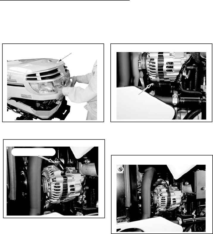
MAINTENANCE/ADJUSTMENTS
106
Fan Belt Replacement
To replace the fan belt, use following procedure:
Open Bonnet. Loosen the alternator pivot nut and
push the alternator toward the engine
to remove the belt.
Loosen the alternator-adjusting bolt.
Install new fan belt and adjust the belt
tension. See Fan Belt Adjustment in
this manual for instructions.
STEP 1
STEP 2
STEP 3
STEP 4
ADJUSTING BOLT
PIVOT NUT
PIVOT NUT
PIVOT NUT
BONNET
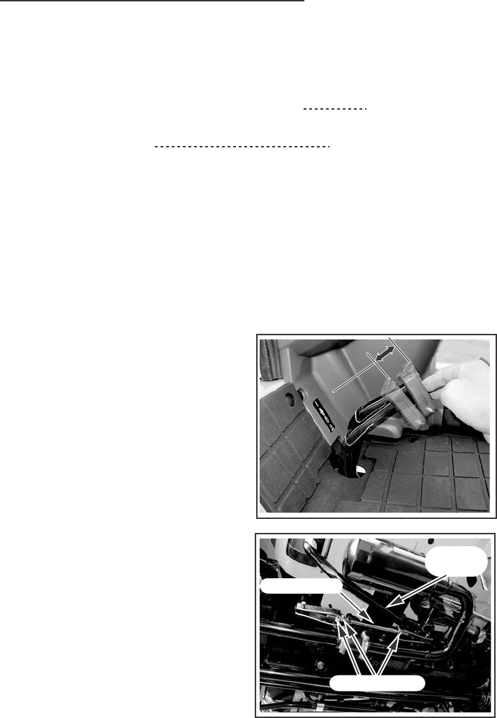
MAINTENANCE/ADJUSTMENTS
107
Rotating fan and belts. Contact can injure. Keep clear.
CLUTCH PEDAL ADJUSTMENT
Service Specifications
Clutch Pedal Check and Adjustment Interval Every 200 hours of
operation or yearly
Free Pedal Movement 20-30mm (0.8 - 1.2 inch)
Free Movement Adjustment
Clutch pedal free movement is very important and must be checked at the
recommended intervals. If there is no free movement, the clutch disc will
wear quickly. If there is too much free movement, the clutch will not
disengage correctly and the transmission will be difficult to shift.
Put the tractor on level ground,
move the range shift lever in the L
position, apply the park brake, stop
the engine and adjust the clutch
pedal free movement as follows:
Push the clutch pedal down by hand,
to measure the amount of pedal free
movement.
The pedal free movement must be
within the specification shown above.
Adjust the pedal free movement as
necessary with the adjusting nuts on
the clutch rod.
To increase free movement, turn the
nuts in.
To decrease free movement, turn the
nuts out. Tighten the nuts to a torque
of 44 to 54 Nm (32 to 40 lb ft).
2020
ADJUSTING NUT
CLUTCH
(PEDAL)
CLUTCH ROD
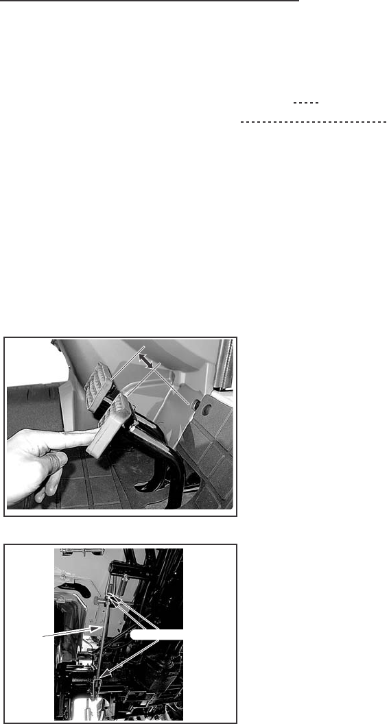
MAINTENANCE/ADJUSTMENTS
108
Rotating fan and belts. Contact can injure. Keep clear.
BRAKE PEDAL ADJUSTMENT
Service Specifications
Brake Pedal Check and Adjustment Interval Every 200 hours or yearly
Free Pedal Movement Specification 35mm (1.4inch)
Brake pedal free play is very important and must be checked at the
recommended intervals. If there is no free movement, the brake shoes will
wear quickly.
If there is too much free movement, accidents may occur. If there is not the
same free movement between LH pedal and RH pedal, it may cause
serious accidents.
Put the tractor on level ground, move the range lever in the L position.
Stop the engine.
Loosen lock nut and rotate the brake
rod to make a free play of 20 to 30 mm
(0.79 to 1.18 in.) at the brake pedal.
With this much play obtained, tighten
the lock nut.
Confirm that the right and left brakes
operate simultaneously by running
the tractor.
If not, adjust both of them by means
of the brake rods.
ADJUSTING NUT
BRAKE
ROD
2020
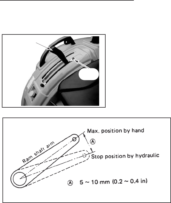
MAINTENANCE/ADJUSTMENTS
109
Rotating fan and belts. Contact can injure. Keep clear.
RAISE STOP SETTING POSITION
If raise stop setting position is incorrect,
the hydraulic pump might be damaged.
Therefore carefully adjust as below.
1. Disconnect an implement from the hitch. (See Disconnecting Implement
from Hitch in this manual.)
2. Disconnect LH and RH lifts rods from the lift arms.
3. Start the engine.
4. Move the hitch control lever rearward to raise the lift arm to the
maximum lifting position.
5. With the arm so raised, stop the engine.
6. Check a free play of the lift arm to be 5 to 10 mm at the tip of the lift
arm by hands.
7. If the insufficient free play is available, move the raise stop forward
and check again with the same procedure as before.
HITCH CONTROL
HITCH CONTROL
LEVER
LEVER
HITCH CONTROL
LEVER
RAISE
STOP

ELECTRICAL SYSTEM
110
Rotating fan and belts. Contact can injure. Keep clear.
SPECIFICATIONS
Electrical System
Type of System 12 Volt, Negative Ground
Battery 12 Volt, 500 CCA
Group 22F, Top Stud Terminals
Alternator 7530/7532 12 Volt, 50 Ampere Output
Voltage Regulator IC Built in Alternator
Starter Motor 7530/7532 12 Volt, 1.7 kw with Solenoid Switch
Head Lamp 25 Watt
Flasher Lamp 27 Watt
Rear Red Lamp 10 Watt
Rear Working Lamp (If Equipped) 23 Watt
Panel Lamp 3 Watt
Turn Indication Lamp 1.4 Watt
Indicator Lamp 1.4 Watt
(a)
15A HAZARD LAMP
(b)
15A HEAD LAMP,TAIL LAMP
(c)
10A
ALTERNATOR,GLOW CONTROLLER
ELECMAGNET PUMP ,ETR SOL
PANEL INDICATOR
AIR HEATER CONTROLLER
(d)
10A TURN LAMP,WORKING LAMP
(e)
15A
IND PTO (7530)
(WORKING LAMP,HORN)

ELECTRICAL SYSTEM
111
GENERAL SERVICE INFORMATION
Alternator Charging System
Follow these general rules to prevent damage to the electrical system:
1. Before working on the electrical system, disconnect the battery cables.
2. Do not make a reverse battery connection.
3. When you use an auxiliary battery for starting, connect positive-to-positive
and negative on the auxiliary battery to the tractor side rail as a ground.
4. When charging the tractor battery, disconnect the battery cables from
the battery terminals. Do not use a battery-charging machine for starting
the tractor.
5. Never operate the tractor when the battery cables are disconnected.
6. When you do maintenance on the engine, prevent foreign material
from entering alternator.
7. If you must do welding, disconnect the battery. Put the welder ground
cable as close as you can to the weld area. Do not put the ground cable
where the current can flow through bearings or along channels with
wire harnesses.
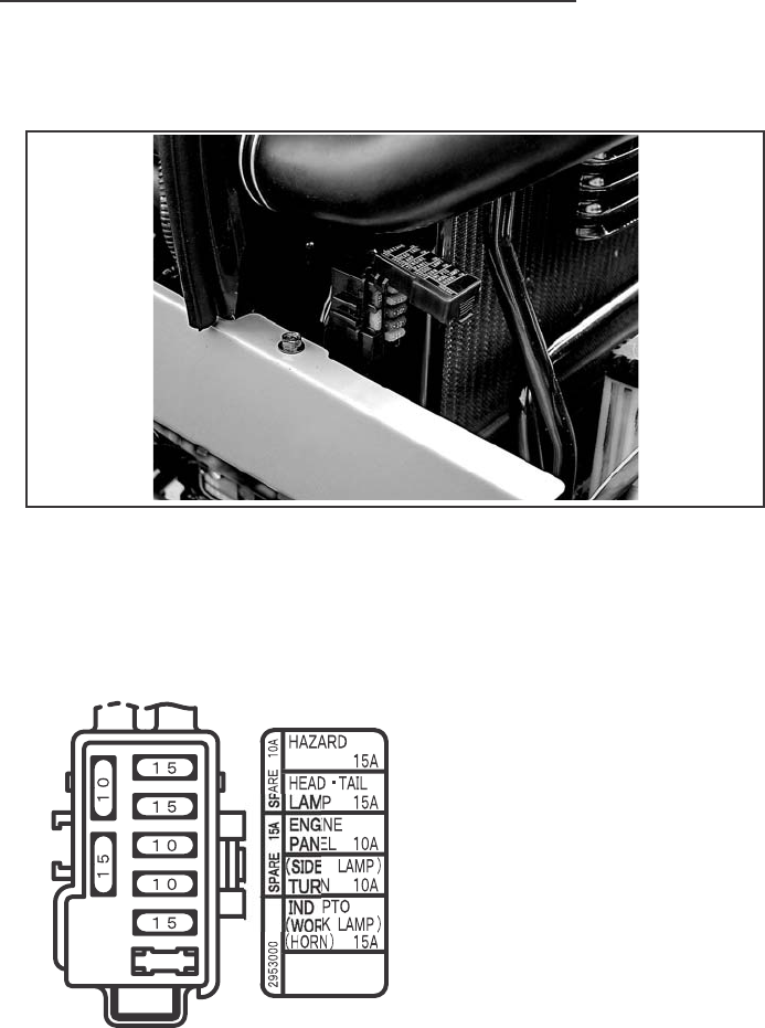
ELECTRICAL SYSTEM
112
Rotating fan and belts. Contact can injure. Keep clear.
Fuses
Cartridge type fuses are used for headlamps, rear red lamp, instrument
lamps, turn signal and flasher lamps, and rear work lamp (if equipped).
The fuses are located in the fuse block, R.H. rear of engine room.
If a short circuit occurs, the fuse will burn out and break the circuit,
preventing damage to the electrical system.
nd
nd
b
b
e
el
d
t
C
C
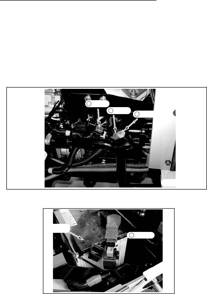
ELECTRICAL SYSTEM
113
Rotating fan and belts. Contact can injure. Keep clear.
Line Fuse
If the electrical circuit is accidently grounded or a reverse battery connection
is made, the Line fuse located on the LH side of the engine will burn out
and break the circuit to prevent the solenoid switch, wiring harness and
alternator charging system from being damaged. If electrical problems
occur, the Line fuse must be checked for continuity to determine if one of
the circuits is broken, see your Dealer to replace and correct.
(1) Protection of an ETR sorenoido circuit
(2) Protection of the main electrical machinery circuits
(3) Protection of a starting switch and a hazard lamp
(4) Protection of an air heater circuit
50MP
50AMP 20AMP
ENGINE LH SIDE
BATTERY
1 50AMP
2 50AMP 320AMP
4 100AMP

ELECTRICAL SYSTEM
114
BATTERY
Auxiliary Battery Connections
Engine can start with transmission in gear when neutral or safety
start switch is by-passed:
1. Do not connect across terminals on starter.
2. Attach a booster battery by connecting the positive terminal of
the booster battery to the "positive terminal" provided or to the
positive terminal of the machine battery. Connect the negative
terminal of the booster battery to the "negative terminal"
provided or to the chassis of the machine.
Then use recommended starting procedures from operators
seat.
3. When necessary repair electrical system components promptly
so that "jump starting" will not be attempted.
Machine run-away can cause injury or death to operator and
bystanders.
When connecting an auxiliary battery or charger to the tractor battery,
make sure you connect positive-to-positive and negative on the auxiliary
battery to the tractor side rail as a ground.
Do not connect auxiliary battery cables across the terminals of the starter.
Start the engine from the operator's seat.
IMPORTANT: This is the only safe method to start the tractor engine with
an external power supply. Any other method of starting can cause injury or
death to the operator or other persons.
Connect the positive (+) cable clamp
of the auxiliary battery to the positive
cable terminal of the tractor battery.
Connect the negative (-) cable
clamp of the auxiliary battery to the
tractor side rail as a ground.
IMPORTANT: Always connect the negative cable last and disconnect
the negative cable first so you do not cause a spark at the battery. A spark
can cause a battery explosion and cause injury.
NEGATIVE(-)
POSITIVE(+)
TERMINAL
ELECTRICAL SYSTEM
115
Battery Cables and Terminals
The battery Terminals must be kept
clean and tight. A good method to
clean terminals is to use Battery Saver.
If Saver is not available, remove all
corrosion with a wire brush, then
wash with a weak solution of baking
soda or ammonia. Put some petroleum
jelly or light grease on terminals to
prevent corrosion.
Removal and Installation of Battery
To remove the battery, disconnect the battery cables and remove the
battery bracket. When the battery is installed, make sure the cables are
installed on the correct terminals. This is a 12-volt, negative ground
electrical system and must be so connected.
NOTE: When disconnecting the battery, remove the negative cable first
from the battery and reconnect it last for safety reasons.
IMPORTANT: Do not start or operate the engine with the electrical system
not completely connected.
WARNING
BATTERIES CONTAIN ACID AND EXPLOSIVE
GAS. EXPLOSION CAN RESULT FROM
SPARKS,FLAMES, OR WRONG CABLE CON-
NECTIONS. TO CONNECT JUMPER CABLES
OR CHARGER, SEE MANUAL(S) FOR THE
CORRECT PROCEDURE. FAILURE TO
FOLLOW THE ABOVE INSTRUCTIONS CAN
CAUSE SERIOUS PERSONAL INJURY OR
DEATH
321-6714

ELECTRICAL SYSTEM
116
When Charging the Battery
IMPORTANT: Battery can explode during boosting or charging. Always
wear proper eye protection, such as a safety goggles.
If the electric circuit inside the battery is broken, charging can generate a
spark inside the battery, which can cause it to explode. If the battery is
discharged, and the reason for discharge is unknown and if the lamps or
horn do not indicate some battery voltage, check the battery with a volt
meter for an open circuit using following procedure.
1. Disconnect the negative (-) cable.
2. Connect the voltmeter across battery terminals.
3. If there is no voltage present, an open internal circuit is indicated.
Replace the battery.
4. If voltage is present, the battery is okay to charge. Charge the battery
with a current of 4 amperes for 5 to 10 hours. To charge the battery
quickly for urgent need, use a current of 25 amperes for 30 minutes or
less. A current larger than specified will cause liquid overflow due to
foaming.
5. The specific gravity of electrolyte of a fully charged battery is 1.280 at
20 C (68 F).
NOTE:
1. If using a battery charger, be certain the charger is turned off before
connecting to the battery.
2. Charge the battery in a well ventilated area.
3. Do not attempt to charge a frozen battery.
When working around storage batteries, remember that all of the
exposed metal parts are "live". Never lay a metal object across
the terminals because a spark or short circuit may result.
When the tractor is not in use, the battery will need a charge every three
mouths to keep the specific gravity at or above 1.240. A storage battery
not in use will slowly discharge. A battery that has discharged can freeze
at low ambient temperature and cause damage to the battery and tractor.
When Battery Is Not in Use

STORAGE
117
STORING THE TRACTOR
When your tractor is not to be used for some time, it should be stored in
a dry and protected place. Leaving your tractor outdoors, exposed to the
elements, will shorten its life. Follow the procedure outlined below when
your tractor is placed in storage for periods up to approximately six months.
See your Dealer for the procedure on longer storage periods.
A. Store the tractor so the tires are protected from light. Before storing
the tractor, clean the tires thoroughly, Jack up the tractor, when it is to be
out of service for a long period. If not jacked up, inflate the tires at regular
intervals.
B. Run the engine long enough to thoroughly warm the oil in the crankcase,
and then drain the oil. Change the oil filter as instructed in Engine Oil Filter.
Refill the crankcase with new oil as specified in Engine Oil Selection in this
manual and run the engine for five minutes.
C. Fill the fuel tank with a good grade of Number Two diesel engine fuel.
If this grade has not been used regularly, drain the fuel and refill. Run the
engine for about five minutes to circulate the fuel through the injection
system.
D. Drain flush and fill the cooling system with an antifreeze mixture ratio
to protect the engine to the lowest anticipated temperature or a minimum
of 50 % antifreeze and add cooling system conditioner. See COOLING
SYSTEM in this manual.
E. Do not remove the battery from the tractor, except for prolonged
storage at below freezing temperature. The battery should be fully changed
to prevent freezing of electrolyte. Disconnect the negative ground cable
at the battery to prevent possible discharge.
F. Clutch assembly may become
bound together if a tractor is not used
for an extended period of time. A
clutch lock latch is provided on your
tractor to lock the clutch in the
disengaged position and should be
used to prevent this condition if your
tractor is not used for an extended
period of time.
CLUTCH LOCK LATCH

STORAGE
118
REMOVING FROM STORAGE
Be sure that the grade of oil in the engine crankcase is as specified in
Engine Oil Selection in this manual.
A. Loosen the fuel tank drain plug and fuel filter cup, and be sure all water
and sediment has drained from the fuel system before closing.
Tighten the drain plug and replace the filter cup.
B. Check the level of the coolant in the radiator.
C. Check engine oil level.
D. Check hydraulic fluid level.
E. See that the battery is fully charged and that the terminal connections
are clamped tightly.
F. On hydrostatic drive tractors, follow the same procedure for starting as
Starting Procedure for Hydrostatic Drive Tractors after Transporting on
truck or flatcar in this manual.
G. Start the engine and let it run slowly.
IMPORTANT: Keep the doors wide open and move the machine outside of
the storage room immediately to avoid danger from exhaust fumes. Do not
accelerate the engine rapidly or operate it at high speed immediately after
starting.
NOTE: CUB CADET CORPORATION reserves the right to make
improvements in design or changes in specifications at any time without
incurring any obligation to install them on units previously sold.
