Cub Cadet 8454 Operators Manual
8454 to the manual 2d47dfb0-01cd-b074-718f-87807435839a
2015-01-05
: Cub-Cadet Cub-Cadet-8454-Operators-Manual-163787 cub-cadet-8454-operators-manual-163787 cub-cadet pdf
Open the PDF directly: View PDF ![]() .
.
Page Count: 56
S
ERIES
8000
CUB CADET LLC P.O. BOX 361131 CLEVELAND, OHIO 44136-0019 [www.cubcadet.com]
Operator’s Manual
PRINTED IN U.S.A. FORM NO. 769-00708
(03/03)
COMPACT TRACTOR
MODEL 8454
ECO
IMPORTANT: READ SAFETY RULES AND INSTRUCTIONS CAREFULLY

2
TABLE OF CONTENTS
TO THE OWNER .................................................................................................................... 2
CALLING SERVICE INFORMATION ...................................................................................... 2
RECORDING MODEL AND SERIAL NUMBER INFORMATION ........................................... 3
IMPORTANT SAFE OPERATION PRACTICES ..................................................................... 4
SAFETY LABELS ................................................................................................................. 10
SECTION 1: CONTROLS AND FEATURES ........................................................................ 12
SECTION 2: OPERATION .................................................................................................... 20
SECTION 3: ADJUSTMENTS .............................................................................................. 30
SECTION 4: TRACTOR MAINTENANCE ............................................................................ 34
SECTION 5: TROUBLESHOOTING ..................................................................................... 50
SECTION 6: SPECIFICATIONS ........................................................................................... 54
WARRANTY ......................................................................................................................... 56
TO THE OWNER
This Operator’s Manual is an important part of your new tractor. The information contained in this
manual has been prepared in detail to help you better understand the features, correct operation,
adjustments, and maintenance of your tractor. The performance and dependability of this tractor rely
greatly on the manner in which it is operated and maintained. Therefore, it is recommended that all
operators of the tractor carefully read this manual and fully understand its operation. Also keep the
manual available for reference to ensure proper operation, and that maintenance procedures are
performed as scheduled to assure the tractor’s optimal mechanical condition.
NOTE: All references to LEFT, RIGHT, FRONT, and REAR, unless specifically stated otherwise,
indicate that relative position on the tractor when facing forward while seated in the operator’s seat.
Your authorized Cub Cadet dealer is interested in the performance you receive from your tractor, and
with the maintenance needed to ensure the satisfactory operation of your tractor. The dealer has
trained service personnel familiar with the latest servicing information, is equipped with the latest
tools, and has a complete line of genuine Cub Cadet service parts which assure proper fit and high
quality.
CALLING SERVICE INFORMATION
The engine manufacturer is responsible for all engine-related issues with regards to performance,
power-rating, and specifications.
If you have difficulties with the tractor and/or equipment; have any questions regarding the operation
or maintenance of this equipment; or desire additional information not found in this manual, contact
your dealer. If you need assistance in locating a dealer in your area, contact the Customer Dealer
Referral Line by calling:
1-877-282-8684
Before calling your dealer, make sure that you have your model number(s) and manufacturing date
available for the dealer.
3
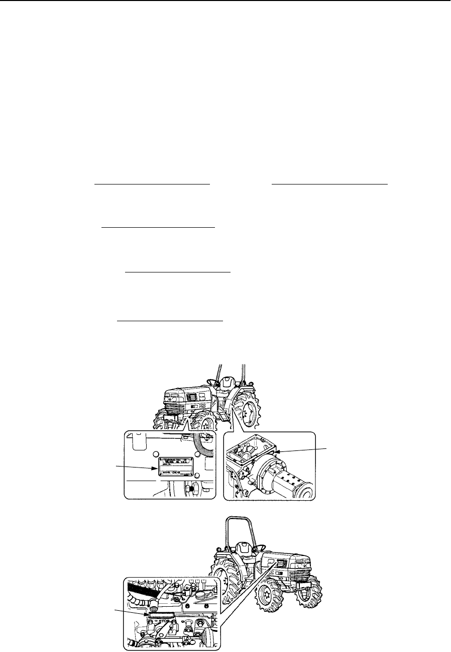
RECORDING MODEL AND SERIAL NUMBER INFORMATION
Product identification plates are provided for major components of your tractor. The numbers on these
plates are important if your tractor should require dealer service, or if you need additional information
on your tractor. Prior to using your tractor for the first time, record the numbers from the identification
plates in the appropriate spaces provided below.
• The tractor model plate is located on the transmission housing on the left side of the tractor.
• The engine serial number is located on the right side of the engine crankcase.
• The transmission serial number is located on the left side of the transmission case near the left
brake case.
• The ROPS information plate is located on the ROPS.
Tractor Model Plate:
Model Number Serial Number
Engine Information:
Engine Serial No.
Transmission Information:
Transmission Serial No.
ROPS Information:
ROPS Serial No.
TRACTOR TRANSMISSION
SERIAL NO.
MODEL
PLATE
ENGINE
SERIAL NO.
4
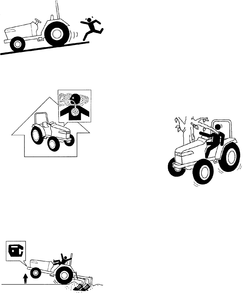
IMPORTANT SAFE OPERATION PRACTICES
WARNING: THIS SYMBOL POINTS OUT IMPORTANT SAFETY INSTRUCTIONS WHICH, IF
NOT FOLLOWED, COULD ENDANGER THE PERSONAL SAFETY AND/OR PROPERTY OF
YOURSELF AND OTHERS. READ AND FOLLOW ALL INSTRUCTIONS IN THIS MANUAL
BEFORE ATTEMPTING TO OPERATE YOUR UNIT. FAILURE TO COMPLY WITH THESE
INSTRUCTIONS MAY RESULT IN PERSONAL INJURY. WHEN YOU SEE THIS SYMBOL,
HEED ITS WARNING.
WARNING:
The engine exhaust, some of its constituents, and certain vehicle components
contain or emit chemicals known to the State of California to cause cancer, birth defects or other
reproductive harm.
WARNING:
This unit is equipped with an internal combustion engine and should not be used on
or near any unimproved forest-covered, brush-covered or grass-covered land unless the engine’s
exhaust system is equipped with a spark arrester meeting applicable local or state laws (if any). If a
spark arrester is used, it should be maintained in effective working order by the operator. In the
State of California the above is required by law (Section 4442 of the California Public Resources
Code). Other states may have similar laws. Federal laws apply on federal lands. A spark arrester for
the muffler is available through your nearest engine authorized service dealer or contact the service
department, P.O. Box 361131Cleveland, Ohio 44136-0019.
DANGER:
Your tractor was built to be operated according to the rules for safe operation in this
manual. As with any type of power equipment, carelessness or error on the part of the operator can
result in serious injury. To help prevent accidents, read and take the following precautions before
operating this tractor. Failure to observe the following safety instructions could result in serious
injury or death.
1. GENERAL OPERATION
• Read, understand, and follow all instructions in
the operator’s manual and on the machine
before starting. Keep this manual in a safe
place for future and regular reference.
• Only allow responsible individuals familiar with
the instructions to operate the machine. Know
controls and how to stop the machine quickly.
• Pay special attention to the warning and
caution labels affixed to the tractor.
• Keep all safety decals clean and readable.
Replace any missing, illegible, or damaged
safety decals.
• Use the handholds and step plates when
getting on and off the tractor to help prevent
accidental falls. Keep the steps and running
boards clear of mud and debris.
• Before driving the tractor in reverse, check to
see that there are no people or obstacles
around.
• Watch where you are going at all times. Watch
for and avoid all obstacles. Be alert at row
ends, near trees and other obstructions.
5
• Never operate the machine while under the
influence of alcohol or drugs, or while fatigued.
• When working in cooperation with others, let
them know in advance what you are doing.
• Always sit in the tractor seat when starting the
engine or operating controls. Do not start the
engine or operate controls while standing
beside the tractor.
• Do not allow anyone but the operator to ride on
the tractor unless a passenger seat is fitted.
Keep bystanders away from the tractor during
operation.
• Never leave a running machine unattended.
Always engage the parking brake, lower imple-
ments to the ground, stop the engine and
remove the key before dismounting.
• Do not modify or alter, or permit anyone else to
modify or alter, any tractor components or any
tractor functions.
• Before starting the engine, sit in the seat,
disengage the clutch, and place the shift levers
in the neutral position.
• Use the ROPS (Roll Over Protective Structure)
and seat belt for safe operation. Overturning
the tractor without a ROPS, or with a ROPS
and the seat belt unfastened, can result in
injury or death.
• Always use the seat belt when the tractor is
equipped with a ROPS. Never us the seat belt
when the tractor is not equipped with a ROPS.
• Whenever possible, adjust the rear wheels to
their maximum tread width to improve stability
of the tractor during operation.
• Engage the parking brake, place the position
control lever in the down position, and place the
transmission levers in neutral before starting
the tractor.
• Avoid accidental contact with control pedals
while the engine is running, as this can cause
unexpected movement of the tractor.
• Shut off the engine and PTO, and engage the
parking brake before getting off the tractor.
6
• Never try to get on or off a moving tractor.
• Never park the tractor on a steep incline.
• Do not run the engine in an enclosed building
without adequate ventilation. Exhaust fumes
can cause death.
• Pull only from the drawbar. Make certain the
drawbar pin is locked in place. Pulling from the
rear axle of the tractor or any point above the
axle could cause the tractor to overturn.
• Maintain the weight balance of the tractor.
Install front end weights to counterbalance
heavy implements attached to the three point
hitch. Do not operate the tractor with a light
front end.
• Check all connections, and tighten if necessary,
before starting the engine or pressurizing lines.
• Do not leave equipment in the raised position
when the vehicle is stopped or unattended.
• Use only accessories approved for this
machine by the manufacturer. Read, under-
stand and follow all instructions provided with
the approved accessory. Know your equipment
and its limitations.
• Use the 3-point hitch only with equipment
designed for 3-point hitch usage.
• Do not operate near embankments, ditches,
holes, or other terrain features which may col-
lapse under the tractor’s weight. The tractor
could suddenly turn over if a wheel goes over
the edge of a cliff or ditch, or if an edge caves in.
• Driving forward out of a ditch or mired condi-
tion, or up a steep slope, increases the risk of
the tractor flipping over backward. Use reverse
to free the tractor in these situations.
• Check overhead clearance carefully before
driving under power lines, wires, bridges or low
hanging tree branches, before entering or
leaving buildings, or in any other situation
where the operator and/or roll bar may be
struck, which could result in serious injury.
• Remember that your tractor, if abused or incor-
rectly used, can be dangerous and become a
hazard both to the operator and to bystanders.
Do not overload, or operate with attached
equipment which is unsafe, not designed for
the particular task, or is poorly maintained.
• Lock the brake pedals together when traveling
at road speeds. Brake both wheels simulta-
neously when making an emergency stop.
Uneven braking at road speeds could cause
the tractor to tip over.
• Watch for traffic when operating near or
crossing roadways. If local laws permit road
travel, use the headlights, flashing hazard lights
and SMV signs when traveling on public
roadways.
• Do not engage the differential lock while
traveling at road speeds. Difficulty steering
could cause you to lose control of the tractor.
• Avoid sudden motions of the steering wheel as
they can lead to a dangerous loss of stability.
The risk is especially great when the tractor is
traveling at road speeds.
7
• Always slow the tractor down before turning.
Turning at high speed may tip the tractor over.
• To avoid upsets, drive the tractor with care and
at a safe speed. Use extra caution when
operating over rough ground, when crossing
ditches or slopes, and when turning corners.
• Wear sturdy work shoes. Never operate the
tractor in bare feet, sandals, or sneakers.
• Do not wear loose fitting clothes or jewelry.
They can be caught in moving parts.
• When towing equipment, use safety chains and
place an SMV emblem on the equipment.
• Any towed vehicle with a total weight exceeding
that of the tractor should be equipped with its
own braking system that is operational from the
tractor seat.
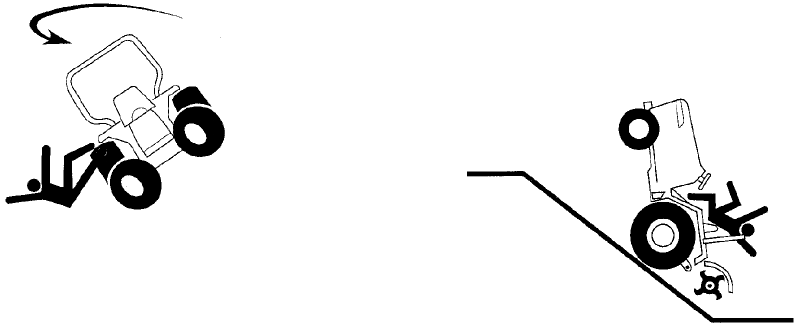
2. SLOPE OPERATION
Slopes are a major factor related to loss of control
and tip-over accidents which can result in severe
injury or death. All slopes require extra caution. If
you cannot back up the slope or if you feel uneasy
on it, do not operate this unit on that area or serious
injury could result.
DO:
• Operate up and down slopes, not across.
• Remove obstacles such as rocks, limbs, etc.
• Watch for holes, ruts or bumps. Uneven terrain
could overturn the machine. Tall grass can hide
such obstacles.
• Place the transmission in the low range. when
climbing or descending slopes. Always keep
machine in gear when going down slopes to
take advantage of engine braking action.
• Follow the manufacturers recommendations for
counterweights to improve stability.
• Keep all movement on the slopes slow and
gradual. Do not make sudden changes in
speed or direction. Rapid engagement or
braking could cause the front of the machine to
lift and rapidly flip over backwards which could
cause serious injury.
• Avoid starting or stopping on a slope. If tires
lose traction, disengage the PTO and proceed
slowly straight down the slope.
DO NOT:
• Do not turn on slopes unless necessary; then,
turn slowly and gradually downhill, if possible.
• Never "free-wheel". Disengaging the clutch or
shifting into neutral while descending a slope
could lead to a loss of control.
3. CHILDREN
• Tragic accidents can occur if the operator is not
alert to the presence of children. Children are
often attracted to the machine. Never assume
children will remain where you last saw them.
• Keep children out of the operating area and in
watchful care of an adult other than the
operator.
• Be alert and turn machine off if children enter
the area.
• Before and when backing, look behind and
down for small children.
• Never carry children. They may fall off and be
seriously injured or interfere with safe machine
operation.
• Never allow children to operate the machine.
• Use extra care when approaching blind cor-
ners, shrubs, trees or other objects that may
obscure your vision of a child or other hazard.
• Remove key when machine is unattended to
prevent unauthorized operation.
8
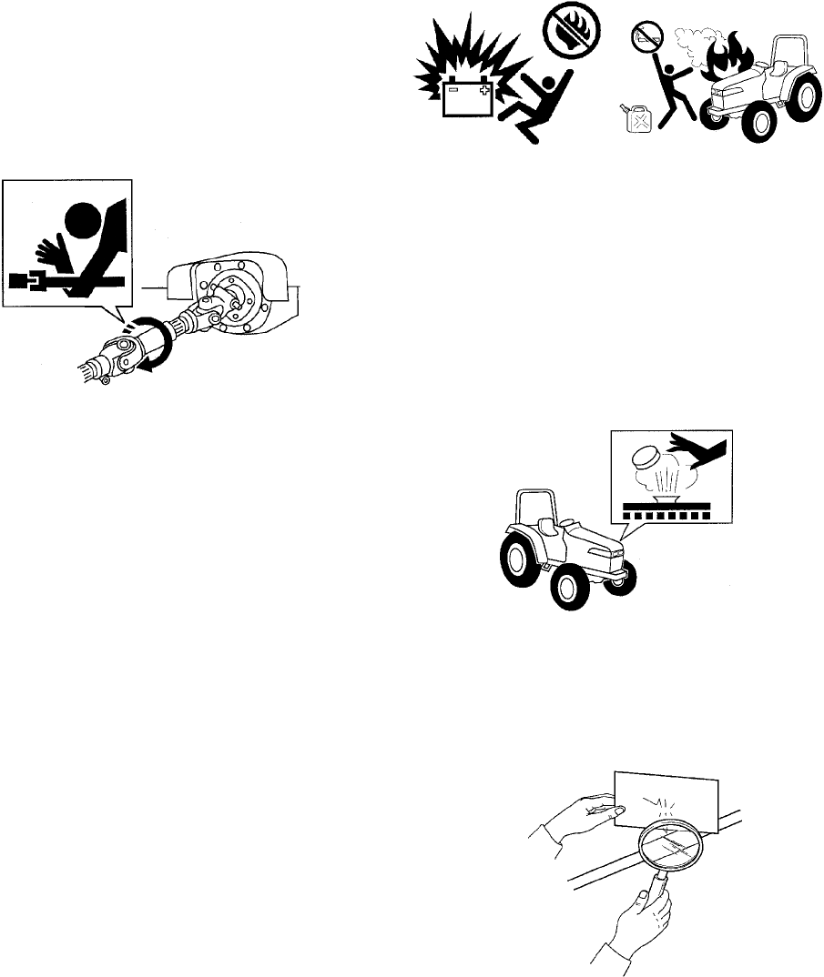
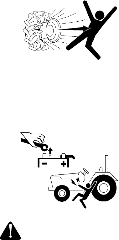
4. OPERATING THE PTO
• Disengage the PTO, stop the engine, and wait
until all moving components have completely
stopped before dismounting the tractor and
connecting, disconnecting, adjusting, cleaning,
or servicing any PTO driven equipment.
• Do not wear loose fitting clothing when
operating the PTO or when near rotating
equipment.
• Keep the PTO shaft cover in place at all times.
Replace the PTO shaft cap when the shaft is
not in use.
• When operating stationary PTO driven equip-
ment, always apply the tractor parking brake
and place chocks behind and in front of the rear
wheels. Stay clear of all rotating parts.
5. SAFETY FRAME (ROPS)
Your tractor is equipped with a rollover protective
structure (ROPS) which must be maintained in a
fully functional condition. Use care when driving
through doorways or spaces with a low overhead.
• Never modify the ROPS in any way.
• Never attempt to straighten or reweld any part
of the main frame or retaining brackets that
have been damaged. Doing so may weaken
the structure and endanger your safety.
• Never secure any parts on the main frame or
attach the safety frame with anything other than
the special fasteners specified.
• Never attach ropes, chains, or cables to the
ROPS for pulling purposes.
• Although the ROPS provides you the maximum
protection possible, never take unnecessary risks.
6. SERVICE
• Use extreme care in handling fuels. They are
extremely flammable and the vapors are
explosive. Use only an approved container.
• Never remove fuel cap or add fuel with the
engine running.
• Replace fuel cap securely and wipe off any
spilled fuel before starting the engine as it may
cause a fire or explosion.
• Do not smoke when working around the battery
or when refueling. Keep all sparks and flames
away from the battery and fuel tank. The
battery presents an explosive hazard because
it gives off hydrogen and oxygen... especially
when recharging.
• Never store the fuel container or machine
inside where there is an open flame or spark,
such as a gas hot water heater, space heater
or furnace.
• The cooling system is under pressure. Never
remove the radiator cap when the system is
hot. Slowly turn the cap the to the first stop to
release pressure before removing the cap. If
the tractor has a coolant recovery tank, add
coolant there instead of to the radiator.
• Escaping hydraulic fluid under pressure can
penetrate the skin. If fluid is injected into the
skin, seek immediate medical attention. Do not
use your hand to check for leaks. Use a piece
of cardboard or paper.
9
• Engine components become hot during
operation and can cause a burn. Allow to cool
down before touching.
• Before "jump starting" a dead battery, read and
follow all of the instructions.
• Do not attempt to mount a tire on the rim. This
should be done by a qualified person with
proper equipment.
• Always maintain the correct tire pressure. Do
not inflate tires above the recommended
pressure shown in the operator’s manual.
• Securely support the tractor when changing
wheels or the wheel tread width.
• Make sure that wheel bolts have been
tightened to the specified torque.
• To avoid sparks from arcing, always discon-
nect the battery’s negative cable first and
connect it last.
• Disconnect negative cable from battery before
working on or near electrical components.
• To reduce fire hazard, keep the tractor free of
any debris build-up. Clean up oil or fuel spillage.
• Before cleaning, repairing or inspecting, make
certain all moving parts have stopped. Keep all
nuts, bolts and screws tight to be sure the
equipment is in safe working condition.
• Never tamper with safety devices. Check their
proper operation regularly.
• Check brake operation frequently. Adjust and
service as required.
• Observe proper disposal laws and regulations.
Improper disposal of fluids and materials can
harm the environment and the ecology.
• Prior to disposal, determine the proper method
to dispose of waste from your local
Environmental Protection Agency. Recycling
centers are established to properly dispose of
materials in an environmentally safe fashion.
• Use proper containers when draining fluids. Do
not use food or beverage containers that may
mislead someone into drinking from them.
Properly dispose of the containers immediately
following the draining of fluids.
• DO NOT pour oil or other fluids into the ground,
down a drain or into a stream, pond, lake or
other body of water. Observe Environmental
Protection Agency regulations when disposing
of oil, fuel, coolant, brake fluid, filters, batteries,
tires and other harmful waste.
• We do not recommend the use of a pressure
washer or garden hose to clean your unit. They
may cause damage to electrical components;
spindles; pulleys; bearings; or the engine. The
use of water will result in shortened life and
reduce serviceability.
WARNING:
- YOUR RESPONSIBILITY: Restrict the use of this power machine to persons who
read, understand and follow the warnings and instructions in this manual and on the machine.
10
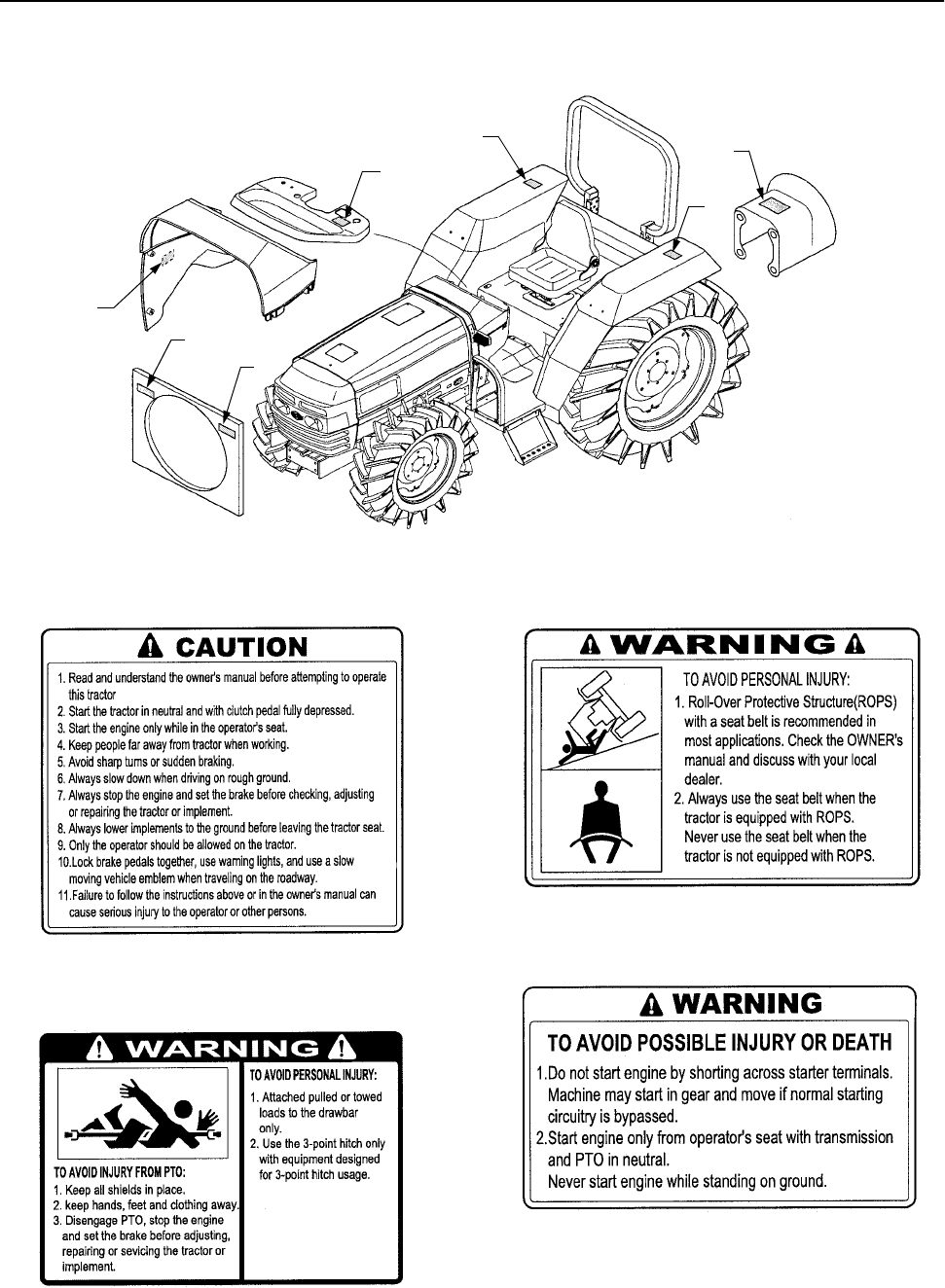
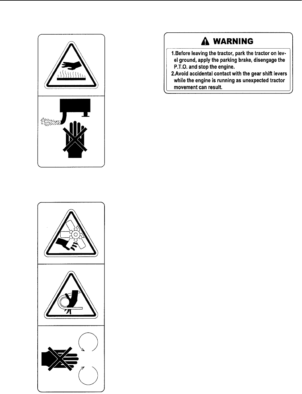
SAFETY LABELS
1. DD-T2325-50512
2. DD-T2325-50743
3. DD-T2325-50724
4. DD-T2241-50702
12
3
4
5
6
7
11
SAFETY LABELS (Cont.)
5. DD-T4625-52361
6. DD-T4625-52351
7. DD-T4625-53191
12
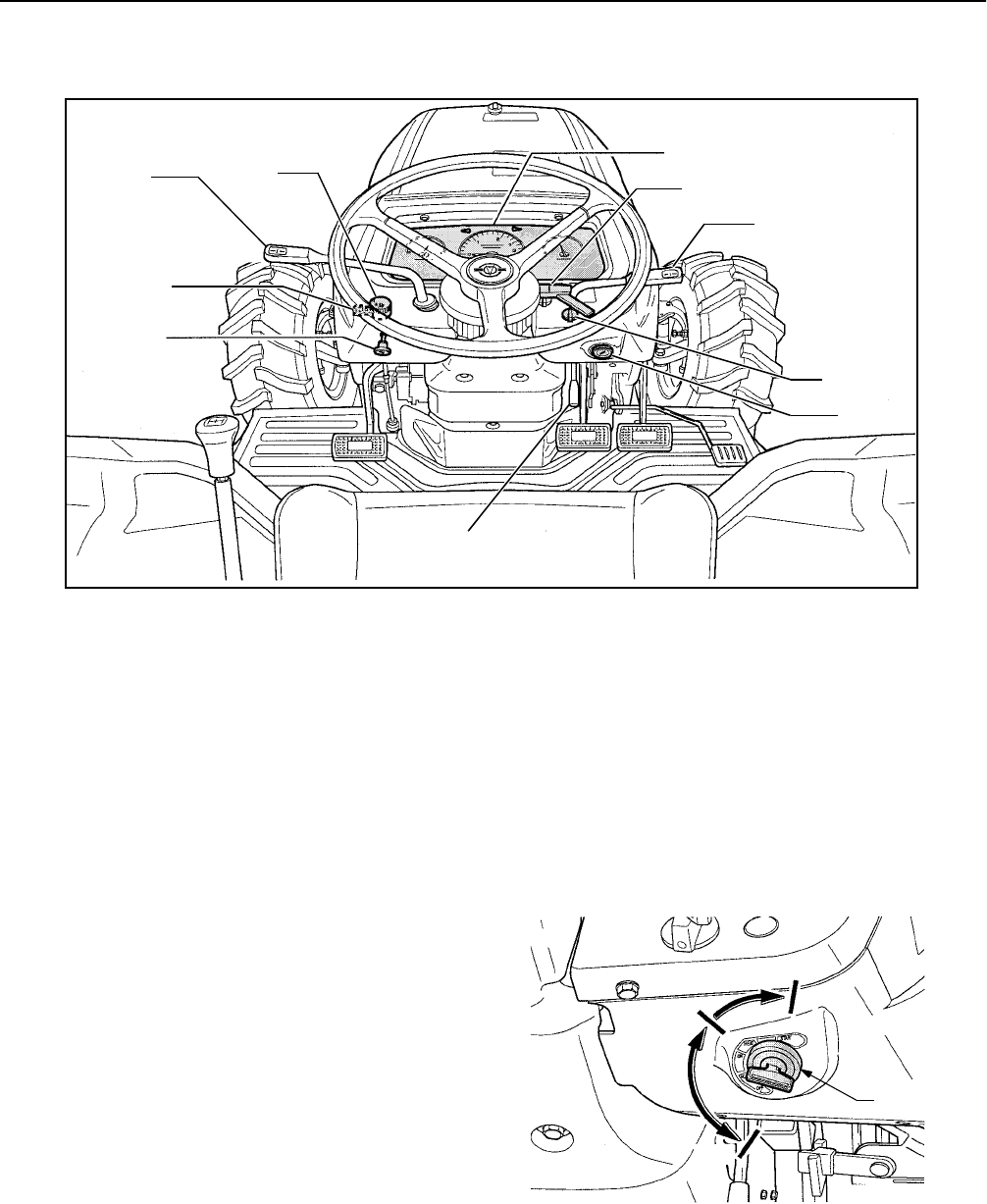
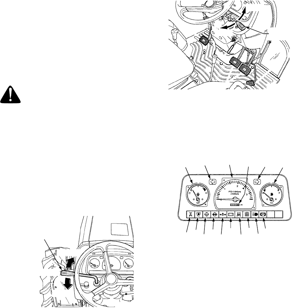
SECTION 1: CONTROLS AND FEATURES
SWITCHES AND DASH MOUNTED CONTROLS
Figure 1
A. Ignition Switch
NOTE: To prevent accidental starting and/or battery
discharge, remove the key from the ignition switch
when the tractor is not in use.
The ignition switch has four positions turning
clockwise as follows (Refer to Figure 2):
OFF - The engine and electrical system is turned off.
ACC - Energizes the accessory circuit.
ON/HEAT - Energizes the tractor’s electrical system.
Warning lamps on the instrument panel are
momentarily illuminating to test the system. Engine
glowplugs are also energized to preheat the
combustion chamber.
START - Activates the starter motor to turn over and
start the engine. When the engine starts release the
key immediately and it will return to the ON position.
NOTE: The safety circuit will prevent the starter from
turning if the clutch pedal is not depressed.
Figure 2
Start
On/Heat
Off
IGNITION
SWITCH
A
B
C
D
E
F
G
H
I
J
F.
G.
H.
I.
J.
Ignition Switch
Light Switch
Turn Signal Switch
Hazard Lamp Switch
PTO Switch
Steering Tilt Lock Lever
Parking Brake Lever
Forward/Reverse Shift Lever
Hand Throttle Lever
Instrument Panel
A.
B.
C.
D.
E.
13
B. Light Switch
Turn the light switch one click clockwise to illuminate
the low beam headlights and the taillights.
Turn the light switch one more click clockwise to
illuminate the high beam headlights. See Figure 3.
Figure 3
C. Turn Signal Switch
Use the switch lever to activate one of the rear amber
lights and hazard lights in a blinking mode to indicate
a turn in that direction. Refer to Figure 3.
Lever downward — Left light flashes
Lever upward — Right light flashes
D. Hazard Lamp Switch
Use to turn on the two amber hazard lights located on
top of the rear fender in the flashing mode. Refer to
Figure 4.
• Pull the switch outward to activate amber lights.
• Push in to turn off.
E. PTO Switch
Use this switch to engage and disengage the 540
RPM rear PTO shaft. See Figure 4.
The PTO switch has three positions as follows:
OFF Position — Center position of switch. Stops the
rotation of the rear PTO shaft.
NOTE: The PTO switch must be placed in the OFF
position before starting the engine. The engine starter
motor will not engage if the PTO switch is not in the
OFF position.
AUTOMATIC Position — Turn top of switch to left.
The PTO will operate only when the 3-point hitch and
its mounted implement are lowered using the position
control lever.
MANUAL Position — Turn top of switch to right. The
PTO will operate continuously until the switch is
returned to the OFF position.
Figure 4
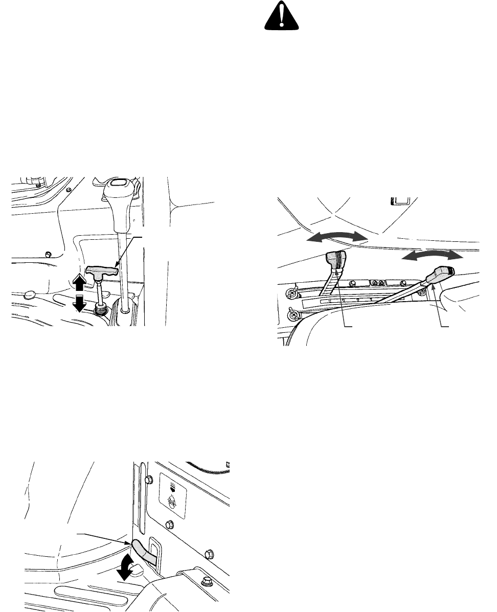
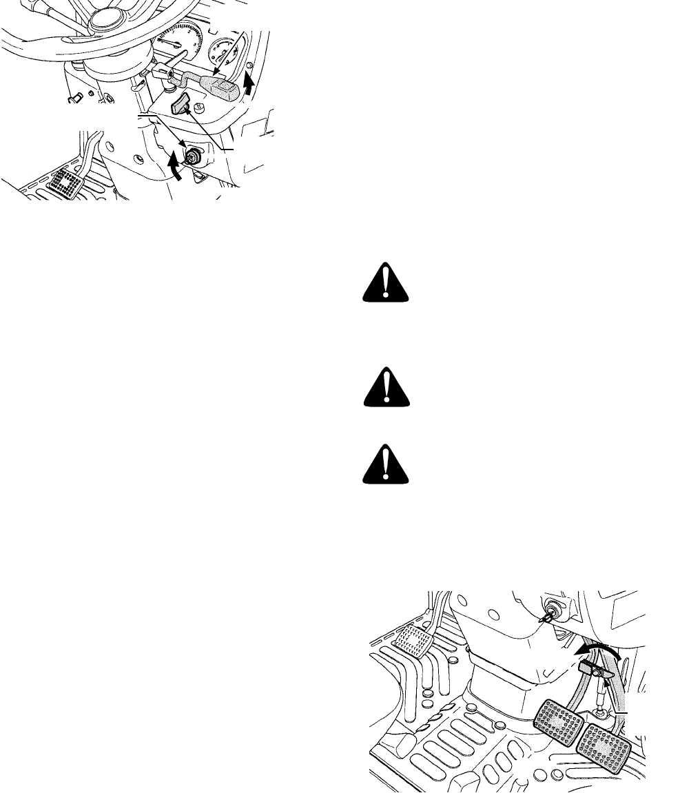
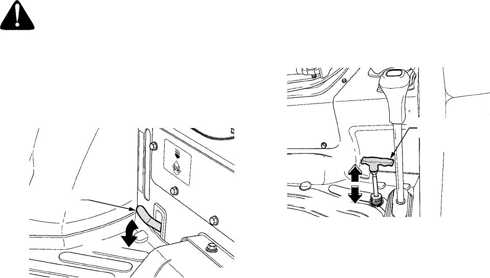
F. Steering Tilt Lock Lever
Use this lever to lock the steering wheel in the tilt
position selected by the operator. See Figure 4.
To reposition the steering wheel proceed as follows:
• Grasp the handle of the lever and push inward.
• Rotate the lever counterclockwise to loosen.
• Adjust the position of the steering wheel.
• Push the handle inward and rotate clockwise until
tight to lock the steering wheel.
• Pull the handle outward.
WARNING: Make sure the steering wheel
is locked before driving the tractor. Never
adjust the steering wheel while in motion.
G. Parking Brake Lever
Use this lever, located below the dash panel to the
right of the steering column, to set the parking brake
before dismounting the tractor. See Figure 5.
Figure 5
Low
Beam
High
Beam
LIGHT
SWITCH
TURN SIGNAL
SWITCH
Manual
Auto.
Off
PTO SWITCH
HAZARD
LAMP
SWITCH
TILT LOCK
LEVER
Engage
PARKING
BRAKE
LEVER
Brake
Pedals
Locked
14
To set the parking brake proceed as follows:
• Lock the right and left brake pedals together
using the brake lock. Refer to Brake Lock in
Floorboard and Fender Mounted Controls later
in this section.
• Fully depress and hold the brake pedals.
• Pull the brake lock lever upward and hold while
while releasing the brake pedals. If properly
engaged, both the lever and the brake pedals will
lock in their present position.
• Depress the brake pedals again to release the
parking brake.
H. Forward/Reverse Shift Lever
Use this lever to set the tractor’s direction of travel.
WARNING: Never shift the forward/
reverse lever without first disengaging
the tractor’s clutch by depressing the
clutch pedal. Failure to do so will result
in severe damage to the transmission.
To change the direction of travel, proceed as follows:
• Fully depress the clutch pedal.
• Shift the lever into one of three positions (See
Figure 6).
Forward position — The tractor will drive in the
forward direction.
Center position — Tractor in neutral.
Rearward position — The tractor will drive in the
reverse direction.
• Slowly and evenly release the clutch pedal.
Figure 6
I. Hand Throttle Lever
When the hand throttle is pushed forward, the engine
speed will increase. When pulled rearward, the
engine speed will decrease.
Figure 7
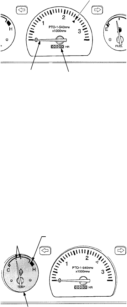
J. Instrument Panel
The instrument panel contains the following gauges
and indicator lights to inform the operator of tractor
conditions (See Figure 8):
Figure 8
1. Tachometer - Indicates the engine speed in
revolutions per minute (RPM). When operating
PTO driven equipment, adjust the engine speed
so that the tachometer needle is at the 540 PTO
rpm mark, unless otherwise specified in the
equipment owner’s manual. See Figure 9.
Forward
Neutral
Reverse
FORWARD/REVERSE
SHIFT LEVER
Fast
Slow HAND
THROTTLE
123
4
5678910 11 12 13 14
15
15
15
Figure 9
2. Hour meter (In Tachometer) - This meter shows
the number of hours the tractor has been oper-
ated at rated engine RPM. The right-most digit
(white background) indicates tenths of an hour.
Monitor the hour meter to ensure all mainte-
nance procedures are completed according to the
maintenance schedule. Refer to Figure 9.
3. Coolant Temperature Gauge - Indicates the
temperature of the engine coolant. Monitor the
gauge to allow the engine to warm up when first
starting the tractor. Do not operate the tractor
under load before the temperature gauge
indicates the proper temperature. Monitor the
gauge to protect against overheating the engine
(the red section on the temperature gauge
indicates overheating). See Figure 10.
Figure 10
4. Fuel Gauge - Indicates the volume of fuel in the
fuel tank.
5. 4WD Indicator - Illuminates when the front drive
lever has been engaged.
6. PTO Indicator - Illuminates when the PTO is
engaged.
7. Coolant Level Lamp - Illuminates if the engine
coolant level falls below a prescribed level. Stop
the tractor and refill the cooling system.
8. Differential Lock Indicator - Illuminates when the
differential lock pedal has been engaged.
9. Engine Oil Pressure Warning Lamp - Illuminates
when the ignition switch is turned on to assure
the light is functioning properly. The light should
go off after the engine starts. If the light remains
on, stop the engine immediately and inspect for
the cause or contact your Cub Cadet dealer.
10. Battery Charge Warning Lamp - Illuminates when
the ignition switch is turned on and should go off
as the engine starts. If the lamp continues to glow
above idle speeds, indicating the battery is being
discharged, stop the tractor and have the electri-
cal system checked for the cause.
11. Glow Plug Indicator - Lights for approximately 10
seconds after the glow plugs are energized, then
turns off to indicate the combustion chambers are
preheated. NOTE: Although the lamp turns off, it
normally takes approximately 20 seconds for the
glow plugs to fully heat a cold engine. The lower
the ambient temperatures, the longer the pre-
heating time needed.
12. Hydraulic Filter Warning Lamp - Illumination indi-
cates a problem with hydraulic oil flow through
the filter.
13. High Beam Lamp - Illuminates when the head-
light switch is turned to high beam position.
14. Parking Brake Indicator - Illuminates when the
parking brake is engaged.
15. Turn Signal Indicators - One of the lamps light in
a flashing mode to indicate that turn signal has
been activated with the turn signal switch.
PTO Mark
TACHOMETER HOURMETER
COOLANT TEMP. GAUGE
Normal
Operating
Range Overheat Range
16
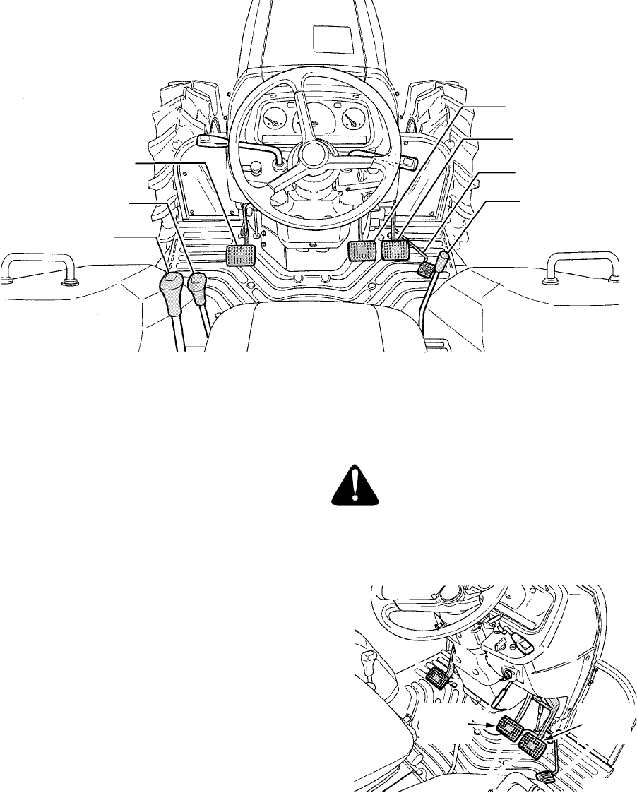
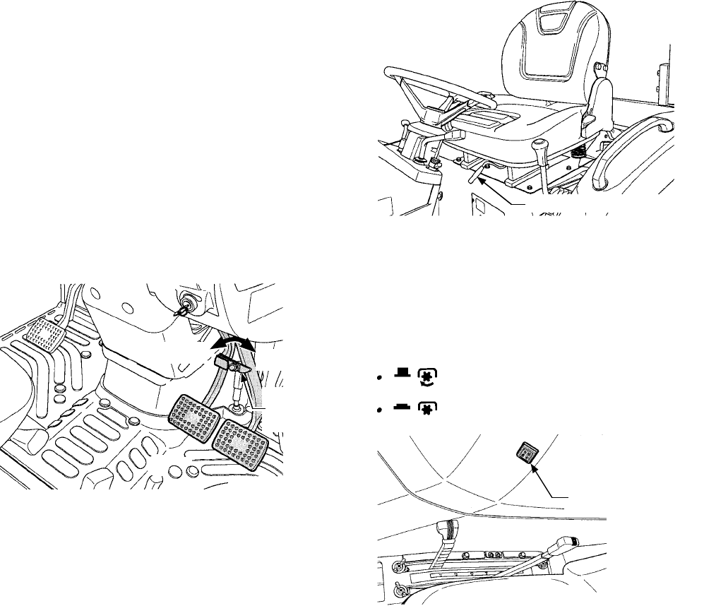
FLOOR BOARD AND FENDER MOUNTED CONTROLS
Figure 11
A. Clutch Pedal
When the clutch pedal is fully depressed, the tractor’s
drive clutch is disengaged. Fully and rapidly depress
the clutch pedal before shifting the main shift lever,
the Hi-Lo Range lever, or the forward/reverse shift
lever. Gradually release the clutch pedal after shifting.
IMPORTANT: The clutch pedal should be rapidly
depressed, but slowly and evenly released to prevent
damage to the clutch plates. Never operate the
tractor with your foot resting on the clutch pedal.
Doing so may contribute to premature clutch wear.
B. Brake Pedals (Right and Left)
• The right (outer) brake pedal engages only the
right brake assembly. Refer to Figure 12.
• The left (inner) brake pedal engages only the left
brake assembly. Refer to Figure 12.
Use the individual brake pedals to assist in making
sharp turns while operating the tractor in the field.
Depress the brake pedal corresponding to the
direction of the turn.
WARNING: Always lock the brake pedals
together before driving the tractor on
roadways or at high transport speeds.
Engaging only one brake under these
operating conditions could cause a
dangerous accident.
Figure 12
A
B
B
C
D
EF
A.
B.
C.
Clutch Pedal
Brake Pedals
Foot Throttle
D.
E.
F.
Main Shift Lever
Hi-Lo Range Shift Lever
Auxiliary Hydraulics Lever
RIGHT
BRAKE
PEDAL
LEFT
BRAKE
PEDAL
17
C. Foot Throttle
The foot throttle is interlocked with the hand throttle.
Depressing the foot throttle increases the engine
speed. Full engine speed control can be obtained
with the foot throttle if the hand throttle is in the full
rearward (slow) position. The foot throttle may also be
used to temporarily increase the engine speed above
the hand throttle setting.
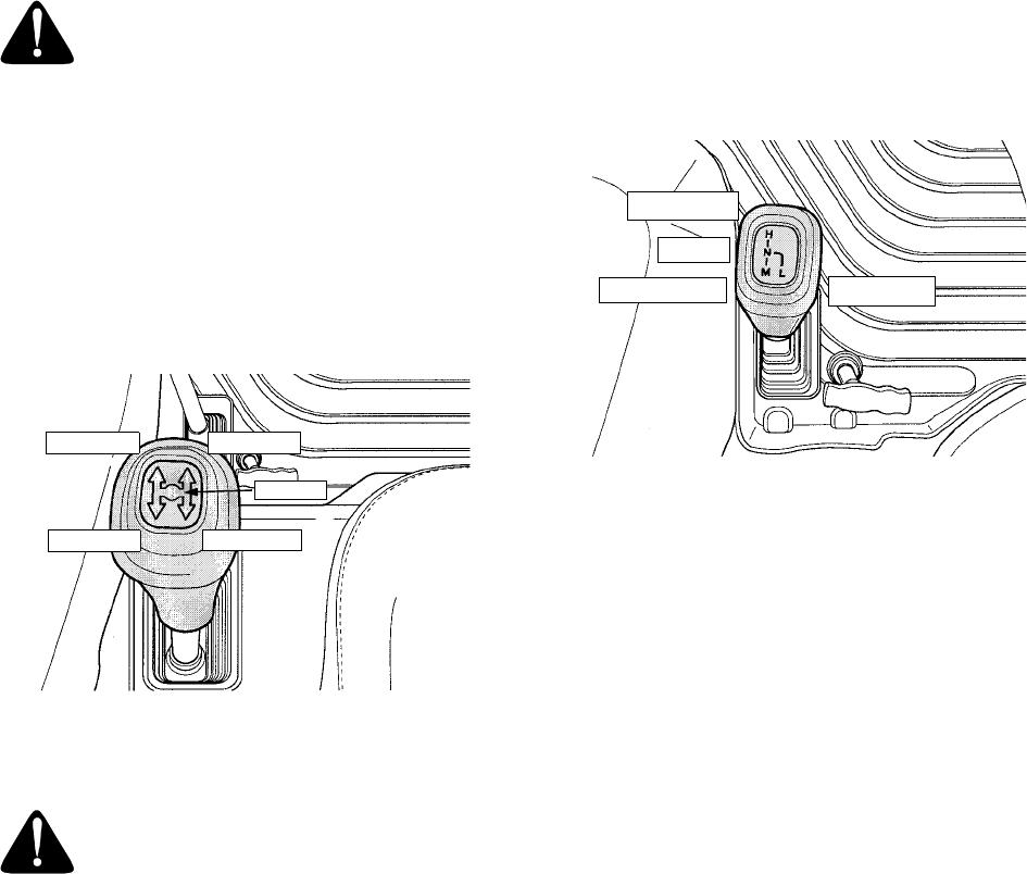
D. Main Shift Lever
WARNING: Never shift the main shift
lever without first disengaging the
tractor’s clutch by depressing the clutch
pedal. Failure to do so will result in
severe damage to the transmission.
The main shift lever allows you to shift the tractor’s
transmission into any of four gear sets. Each gear set
represents a change in tractor speed, with 1 being the
slowest speed and 4 the fastest. The synchromesh
type gearbox allows you to change gears without
stopping by just fully depressing the clutch pedal.
The shift pattern is in the form of an "H" with the cen-
ter position being neutral. See Figure 13.
Figure 13
E. Hi-Lo Range Shift Lever
WARNING: Never shift the Hi-Lo range
shift lever without first disengaging the
tractor’s clutch by depressing the clutch
pedal. Failure to do so will result in
severe damage to the transmission.
The Hi-Lo range shift lever allows you to shift the trac-
tor’s transmission into any of three speed ranges (See
Figure 14).
To shift into the High, Middle, or Low range, com-
pletely stop the tractor and fully depress the clutch
pedal.
• Move the lever to the left and forward to shift into
the High (faster) range.
• Move the lever to the left and rearward to shift
into the Middle (medium) range.
• Move the lever to the right and rearward to shift
into the Low (slower) range.
• Move the lever to the center position to place in
neutral.
Figure 14
Use in combination with the main shift lever and the
forward/reverse lever to obtain twelve speeds in for-
ward and twelve speeds in reverse
F. Auxiliary Hydraulics Lever
Use this lever to control the cylinder positions of
optional implements attached to the remote hydraulic
outlets of the tractor.
IMPORTANT: Do not hold the lever in the "Pull" or
"Push" position once the remote cylinder has reached
the end of its stroke. Doing so will force oil through
the relief valve, and over a prolonged period cause
the hydraulic oil to overheat.
1st Speed
2nd Speed
3rd Speed
4th Speed
1
2
3
4
N
Neutral
High Range
Low Range
Neutral
Middle Range
18
Front Wheel Drive Lever
The front wheel drive lever is located in the
floorboard, below and to the left of the seat.
Use the front wheel mechanism only when additional
traction is needed to drive the tractor. For example:
when operating ground engaging equipment such as
a front end loader; when climbing slopes; or when
operating in wet, sandy or loose soil conditions.
• To engage the front wheel drive mechanism,
depress the clutch pedal and push the front
wheel drive lever downward. See Figure 15.
• To disengage the front wheel drive, depress the
clutch pedal and pull the lever upward.
Figure 15
Differential Lock Pedal
Located at the rear of the right floor board, the differ-
ential lock is used to gain additional traction when
operating the tractor on wet or loose soil. When the
pedal is depressed the rear wheels of the tractor are
prevented from rotating independently of one another.
See Figure 16.
Figure 16
WARNING: When operating with the
differential lock engaged, the tractor will
be difficult to steer. To prevent loss of
control of the tractor, do not drive the
tractor on roadways or at speeds above 5
MPH with the differential lock engaged.
• To engage the differential lock, lightly step on the
differential lock pedal with your heel.
• To disengage, simple release the pedal.
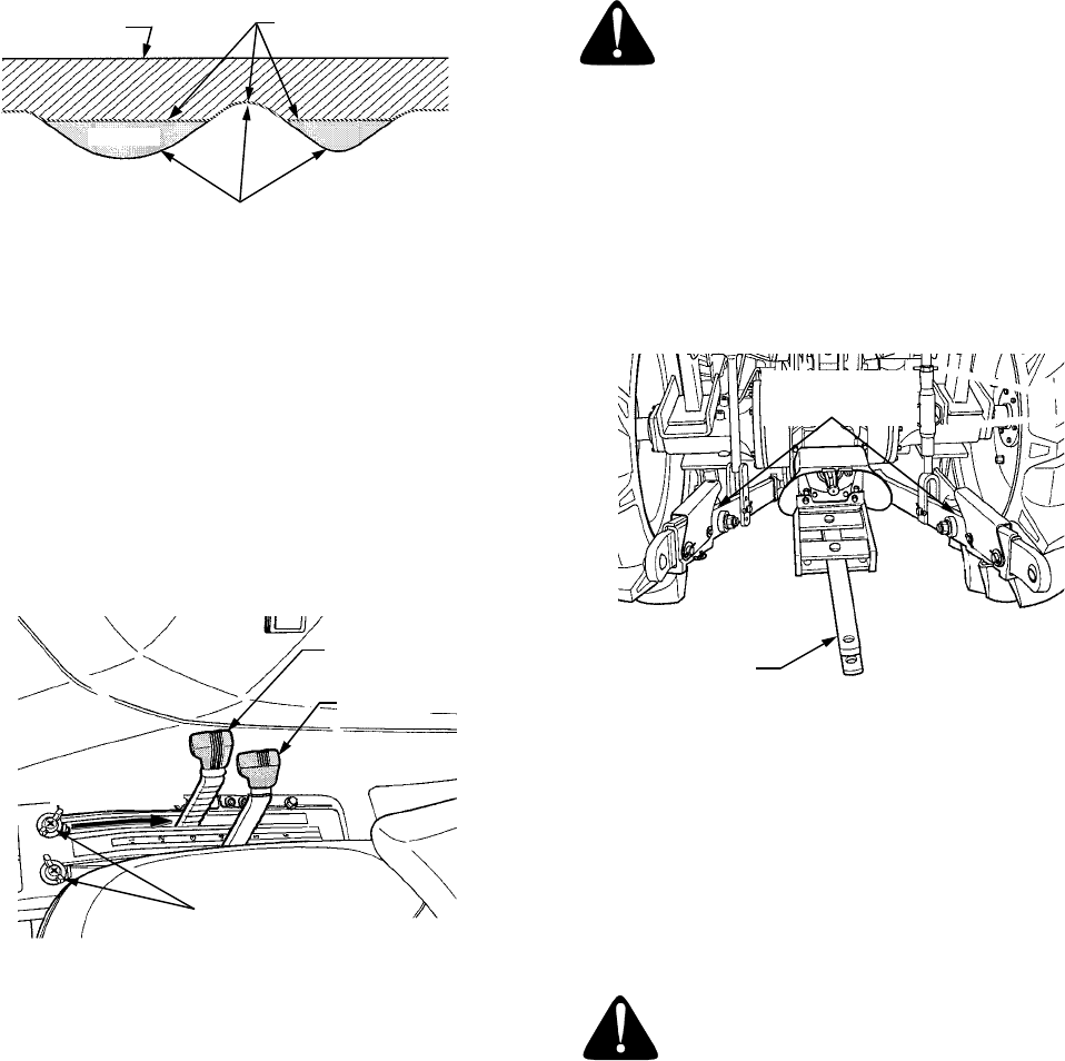
Hydraulic Control Levers
The hydraulic control levers, consisting of the position
control and draft control levers, are located on the
right fender. See Figure 17.
Figure 17
Use these control levers to control the working depth
and pull of implements attached to the three point
hitch as follows:
• Using Position Control — This will control the
working depth of 3-point implements regardless
of the amount of pull required. Push the draft
control lever forward to the lowest position and
set the implement working depth by moving the
position control lever to the desired position.
• Using Draft Control — This will control the pull of
the 3-point implement. As the pull on the 3-point
hitch changes due to various soil conditions, the
draft control system automatically responds to
these changes by either raising or lowering the
implement slightly to maintain a constant pull.
Push the position control lever forward to the
lowest position and set the implement pull by
moving the draft control lever to the desired
setting.
FRONT WHEEL
DRIVE LEVER
Engaged
Disengaged
Engage
DIFFERENTIAL
LOCK PEDAL
POSITION
CONTROL
LEVER
DRAFT
CONTROL
LEVER
Raise
Raise
Lower
Lower
19
• Using Mixed Control — In draft control, when draft
decreases, the implement automatically lowers to
increase draft. However, the implement some-
times lowers too much. To limit the degree the
implement can be lowered, set the position control
lever at the lowest working depth desired for the
implement; then lower the draft control lever to the
point where the implement is at the desired depth.
This stops the implement from going too deep and
also controls the pull to prevent loss of traction and
ground speed.
Brake Pedal Lock
The brake pedal lock is located on the right brake
pedal. Flip the lock counterclockwise so it engages
the bracket on the left brake pedal to interlock both
brake pedals. See Figure 18.
Figure 18
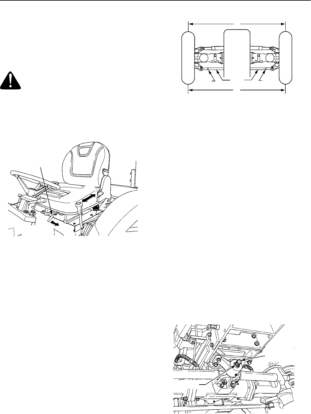
Seat Adjustment Lever
The seat adjustment lever is located beneath the left
side of the seat. This lever is used to adjust the seat
forward or backward to the desired operating position.
See Figure 19.
Figure 19
PTO Safety Switch
Located on the right fender. To stop the PTO in an
emergency, depress the switch. The switch must be
pressed a second time (switch button in the up
position) to re-engage the PTO. See Figure 20.
Figure 20
BRAKE
PEDAL
LOCK
Engage Disengage
SEAT ADJUSTMENT LEVER
OFF
ON
- On
- Off
PTO
SAFETY
SWITCH
20
SECTION 2: OPERATION
ROLLOVER PROTECTIVE STRUCTURE (ROPS)
This tractor is equipped with a foldable Rollover
Protection Structure (ROPS) and seat belts. When
used together they are effective in reducing injuries to
the operator in the event of an accidental tractor
rollover. The safety provided by the ROPS is
minimized if the seat belt is not properly adjusted
AND buckled.
WARNING: Always wear the seat belt
when operating the tractor equipped with
a ROPS. However, if the ROPS is in the
folded position or has been re-moved, the
seat belt must not be used.
Use the following guidelines when using a tractor
equipped with a ROPS:
• Be aware of overhead clearances in the area of
operation. Check for clearance of door (or gate)
openings and other overhead objects such as
utility lines and tree branches. Overhead objects
could catch the ROPS and upset the tractor.
• Do not modify the ROPS by drilling holes for, or
welding accessories to the structure.
• Do not use the ROPS to pull objects with the
tractor. Use ONLY the tractor drawbar for pulling.
• In the event of an accident, have the ROPS
carefully inspected and, if necessary, replaced by
your Cub Cadet dealer. Do not attempt to repair
the ROPS.
PRE-STARTING CHECKS
Perform the following checks every day before start-
ing and operating the tractor.
• Check the air pressures and general condition of
the tires.
• Check under the tractor for any indications of oil
or water leakage.
• Check that all lamps and lights work properly.
• Walk around the tractor and inspect for loose
fasteners.
• Check the transmission oil level.
• Check the engine oil level.
• Check the engine coolant level.
• Check that the air cleaner is free of obstructions
and excessive dirt.
• Check the fuel supply.
• Check operation of the clutch and brake pedals.
• Check operation of the parking brake.
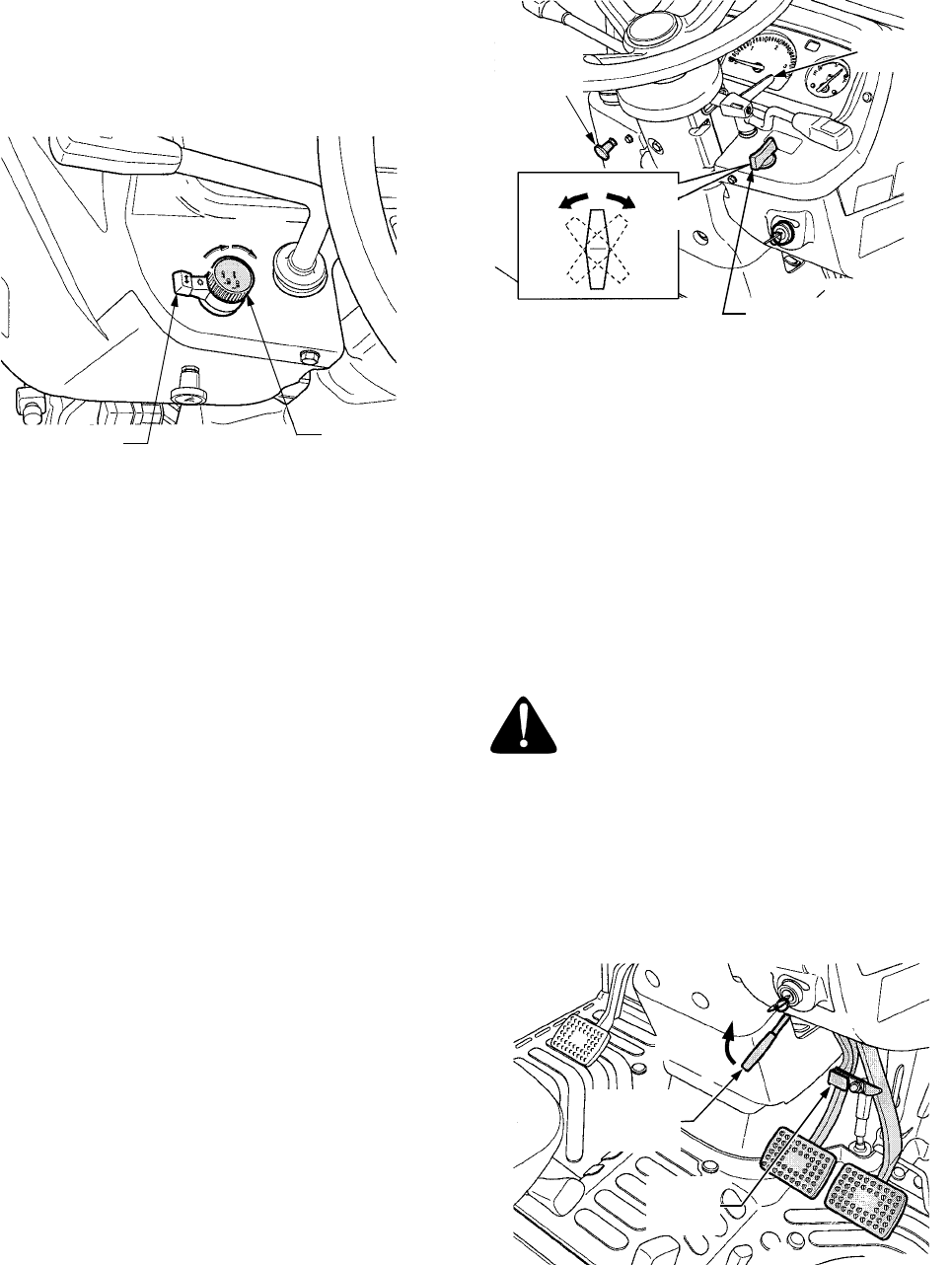
FUELING THE TRACTOR
Fill the fuel tank with only clean, fresh, diesel fuel. To
ensure the freshness of the fuel, purchase fuel in a
quantity that can be used within 30 days.
NOTE: DO NOT USE KEROSENE OR GASOLINE in
your diesel engine. Damage to the engine will occur.
Generally a good grade Number Two Diesel Fuel
should be used in your diesel engine. However, in
extremely cold temperatures a quality Number One
Diesel Fuel, or a blend of Number One and Number
Two Diesel fuels should be used. In most areas,
diesel fuel is properly blended for seasonal use as
ambient temperatures change. Therefore, it is
important to monitor fuel purchases so that seasonal
grade fuels are not carried over after the average
ambient temperature has changed.
WARNING: Never fill the fuel tank to the
top of the filler neck. Expansion could
result in overflow through the vents in
the cap.
• Do not smoke while refueling the tractor.
• Do not fill the fuel tank when the engine is
running or while the engine is hot.
• The fuel fill cap is located beneath the small
access door in the rearward end of the hood.
Press downward on the rear of the door to open.
See Figure 21.
Figure 21
IMPORTANT: Use of a strainer when refueling is rec-
ommended to prevent impurities from entering the
fuel system and causing contamination of the injec-
tion pump.
• Unscrew the fuel cap and fill tank from an
approved container. Do not fill the fuel tank to
capacity. Allow room for expansion.
ACCESS
DOOR
FUEL CAP
21
• Tighten the fuel cap securely, and immediately
wipe up any spilled fuel.
• To minimize condensation, keep the fuel tank as
full as possible without filling to capacity. It is a
good practice to fill the fuel tank at the end of the
day to reduce overnight condensation.
• Do not allow the fuel tank to run dry. Running out
of fuel requires bleeding air and priming the fuel
system.
WARNING: Fuel in the engine injection
system is under high pressure. If not a
qualified mechanic, do not attempt to
service the fuel injection system. Do not
use your hand to check for leaks.
NEW TRACTOR BREAK-IN PROCEDURES
A new tractor is built with high tolerance, well fitted
components, but various parts require a break-in
period before being subjected to severe work loads.
The manner in which the tractor is handled during the
"break-in" period greatly affects the life of the tractor.
Therefore, to obtain the maximum performance and
longest service life from the tractor, it is very
important to properly break-in the tractor. Care should
be taken during the first 100 hours of operation to
operate the tractor at slower speeds and to avoid
excessive work loads. In handling a new tractor the
following precautions should be observed.
• Do not operate the tractor at full speed for the
first 100 hours.
• Do not start quickly or apply the brakes suddenly.
• Never operate a new engine immediately under
full load. Allow the engine to warm up.
• Avoid operating the engine for prolonged periods
at either high or low speeds with no load.
• Use the transmission’s middle (or low) speed
range for heavy loads to avoid lugging down the
engine due to overload.
• Closely monitor the engine oil and coolant levels,
and keep filled to the recommended levels.
• As parts "break-in", minute particles of material
may break away, and could cause wear to the
component. Therefore, it is very important to
perform all break-in maintenance procedures
found in the MAINTENANCE section.
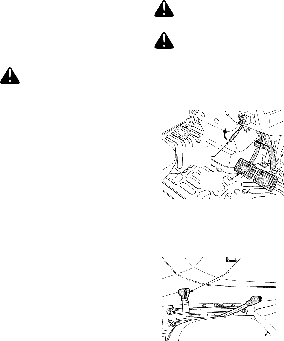
STARTING THE ENGINE
WARNING: Always sit in the operator’s
seat when starting the tractor, Never
attempt to start the engine while standing
beside the tractor.
WARNING: Never use a starting fluid,
such as ether, as a starting aid. Using a
starting fluid could cause severe engine
damage or a fire, and will void the engine
warranty.
• Sit in the operator’s seat, adjust the seat position
(see ADJUSTMENTS), and fasten the seat belt
(only if a ROPS is installed and in the up
position).
• Engage the parking brake. See Figure 22.
Figure 22
• Place the main gear shift lever, Hi-Lo range shift
lever, and the PTO switch in the neutral position.
• Place the position control lever in the lowest
position. See Figure 23.
Figure 23
Engage
PARKING
BRAKE
LEVER
Depress
Brake
Pedals
Position Control
Lowest Position
22
• Set the throttle lever approximately 1/4 of the way
forward (approximately 1500 RPM position).
Figure 24
• Turn the ignition switch to the "ON/Preheat"
position. Refer to Figure 24.
NOTE: Some of the instrument panel lamps will
light momentarily to indicate they are functioning.
The oil pressure and battery charge lamps should
remain on until the tractor is started.
• Observe the glow plug indicator light on the
instrument panel — it should go out after approxi-
mately 10 seconds, indicating the combustion
chamber has been preheated. However, allowing
the glow plugs to preheat an additional 10 sec-
onds (or longer in colder ambient temperatures)
is recommended.
NOTE: It is not normally necessary to preheat the
engine when restarting after its been warmed up.
• Fully depress the clutch pedal.
• Turn the ignition key to the “START” position and
release it as soon as the engine starts; however,
do not crank the engine continuously for more
than 10 seconds at a time. If the engine does not
start within this time, turn the key to “OFF” and
wait at least 30 seconds to allow the engine’s
starter motor to cool. Try again after waiting.
• Slowly release the clutch pedal and allow the
engine to run at medium speed for 5 to 10
minutes (depending on ambient temperatures) to
warm the tractor before operating under load.
IMPORTANT: The engine oil pressure and battery
charge lights should turn off. If they do not, stop the
engine immediately and check for the cause or
contact your Cub Cadet dealer.
STOPPING THE ENGINE
• Reduce the engine speed to idle using the hand
throttle lever and apply even foot pressure on
both brake pedals.
• Depress the clutch pedal and place the main shift
lever and Hi-Lo range shift lever in neutral.
• Turn the PTO switch to the neutral (OFF)
position.
• Use the position control lever to lower equipment.
• Allow the engine to idle for a short period of time.
NOTE: Stopping a hot engine at high speed may
cause internal engine damage.
• Interlock the brake pedals using the brake pedal
lock and set the parking brake using the parking
brake lever.
• Turn the ignition switch counterclockwise to the
OFF position to stop the engine.
WARNING: To prevent unauthorized
operators from starting the tractor,
always remove the key from the ignition
switch when leaving the tractor.
DRIVING THE TRACTOR
WARNING: Always allow the engine to
warm up before applying load. Avoid
sudden starts, excessive speed and sud-
den stops.
WARNING: Always look behind and
down for bystanders or obstacles before
operating the tractor in the reverse
direction
• If transporting the tractor to a job site or traveling
on roadways, make certain the two brake pedals
are interlocked. See Figure 25.
Figure 25
PTO Switch
In Neutral
On/Preheat
Position
Throttle Lever
1/4 forward
BRAKE
PEDAL
LOCK
Engage
23
• Fully depress the clutch pedal and proceed as
follows:
- Shift the Forward/Reverse Shift Lever to desired
direction. See Figure 26.
Figure 26
- Shift the Main Shift Lever to desired gear speed.
See Figure 27.
- Shift the Hi-Lo Range Shift Lever to desired
range. See Figure 27.
Figure 27
• Pull the position control lever rearward to raise the
attachment.
• Momentarily depress the brake pedals to disen-
gage the parking brake. Refer to Figure 28.
• Throttle up the engine to a moderate speed using
either the hand throttle or foot throttle. See Figure
28.
Figure 28
• Slowly release the clutch pedal to start the tractor
moving.
NOTE: If operating power driven equipment running
off the PTO, the throttle must be increased to the 540
PTO mark unless otherwise specified in the
equipment operator’s manual. Use the gear shift
levers to select a safe travel speed. Proper travel
speed will depend on the type of equipment and the
condition of the terrain.
IMPORTANT: Do not drive with your foot resting on
the clutch pedal. Partial engagement of the clutch will
cause clutch slippage and result in premature wear of
clutch components.
STOPPING THE TRACTOR
• Reduce the engine speed by pulling the hand
throttle rearward and remove your foot from the
foot throttle.
• Evenly depress both brake pedals to stop the
tractor.
• Depress the clutch pedal and place the main shift
lever and Hi-Lo shift lever in neutral.
• Push the position control lever forward to lower
equipment to the ground.
• Interlock the brake pedals and fully depress and
hold the brake pedals.
• Pull the brake lock lever upward and hold while
releasing the brake pedals to engage the parking
brake.
Forward
Reverse
Select
Gear
Speed
Select
Speed
Range
Depress
Clutch
Pedal
Disengage
Parking Brake
Throttle Up Using
Hand or Foot
Throttle

24
• If leaving the tractor, turn the ignition key to the
OFF position and remove the key.
• If parking on an incline, chock the wheels to
prevent accidental rolling of the tractor.
TURNING THE TRACTOR
WARNING: Turning the tractor while
traveling at a fast speed may cause the
tractor to overturn.
NOTE: The tractor is equipped with hydraulic power
steering. If front mounted equipment is installed on
the tractor and the engine is running at a slow speed,
it may take increased steering effort to turn the
tractor.
IMPORTANT: When the steering wheel is turned
completely and held in this position, the hydraulic
system may emit a high pitched sound from the relief
valve being actuated. Avoid prolonged turns with the
tractor’s steering wheel held in the completely turned
position.
• Always slow down the tractor by reducing throttle
speed and/or downshifting the transmission
before turning the tractor.
• Engagement of the differential lock will prevent
proper steering and could cause loss of tractor
control when turning. Always release the
differential lock pedal and make the certain it is
disengaged before turning the tractor.
• Use the individual wheel brakes to assist turning
ONLY when the tractor is working in the field and
operating at slower speeds.
WARNING: Sudden application of one
brake while traveling at high speed or
while making fast turns could cause the
tractor to roll over.
DRIVING ON SLOPES
WARNING: When climbing or descending
a hill, do not shift the transmission into
the neutral position or disengage the
clutch.
• Interlock the brake pedals before operating the
tractor on a slope. Never use the individual wheel
brakes when operating on a slope.
• Operate the tractor up and down slopes, never
across slopes. Do not drive so that the tractor
may tip over sideways.
• Prior to going uphill, shift the transmission into a
low enough gear to allow the tractor to climb the
hill without lugging down the engine.
• Prior to going downhill, reduce the engine speed
and shift the transmission into a lower gear to
take advantage of the braking action of the
engine.
• Before operating the tractor on a slope, walk the
slope to look for possible hazards such as rocks,
mounds, stumps, or surface irregularities which
could cause the tractor to be upset.
• Back the tractor with attachment up the steepest
portion of each slope you intend to work. If the
tractor cannot negotiate the slope in reverse, the
slope is too steep to be worked.
• Avoid turns when driving on a slope. If a turn
must be made, turn down the slope. Turning up a
slope greatly increases the chance of a roll over.
• Avoid stopping when driving up a slope. If it is
necessary to stop while driving up a slope, start
up smoothly and carefully to reduce the
possibility of flipping the tractor over backward.
DRIVING ON ROADWAYS
WARNING: Ensure proper weighting of
the tractor, and travel at a safe speed
when driving with a rear mounted imple-
ment in the raised position. Bouncing of
the implement while traveling at higher
speeds could momentarily raise the front
end of the tractor and result in loss of
steering and control of the tractor.
• Make certain the left and right brake pedals are
interlocked before driving on public roads.
• Attach an SMV (slow moving vehicle) sign in a
visible location on the back of the tractor or rear
mounted equipment.
• Reduce the speed of the tractor when turning on
sharp curves.
• Downshift the transmission and use the engine to
brake when descending steep slopes.
• Use the turn signal to alert other vehicles of your
intentions when making turns.
• If driving after dusk or before dawn, turn on all the
tractor lights - including the flashing hazard lights.
Dim the headlights to oncoming traffic if using the
high beams.
• Pay close attention for low shoulders on the side
of the road. Dropping the tractor’s wheels off the
road onto a low shoulder could upset the tractor.
• Obey all traffic laws and allow faster moving
vehicles to pass. Do not block the road.

25
CHECK WHILE OPERATING
While operating the tractor, regularly check the
gauges and warning lights on the instrument panel to
ensure the tractor is functioning properly.
Coolant Temperature Light
Regularly check that the gauge needle is within the
normal operating range. If the needle moves into the
red section (overheat) of the gauge, stop the tractor
immediately and check for the following causes:
WARNING: After the engine has been
running for a short period, the radiator,
muffler, engine block, and any metal sur-
face in close proximity to the engine will
be HOT. Allow these areas to cool and
use extreme caution to avoid burns.
WARNING: Do not remove the radiator cap
until the coolant temperature is below its
boiling point. Then carefully loosen the
cap to its first stop to relieve any pressure
before completely removing the cap .
• Check the coolant level. If coolant is low check for
possible cause, such as a radiator or hose leak.
• Check for debris on the screen in front of the radi-
ator. Check the passages between the radiator
cooling fins for accumulations of dust or dirt.
• Check for a loose fan drive belt.
• Check for internal radiator blockage.
Engine Oil Pressure Lamp
The oil pressure lamp alerts the operator that the
engine oil pressure is below the prescribed level. If
the lamp should light during operation, stop the
engine immediately.
• Check the engine oil level. If the oil level is within
the operating range, contact your Cub Cadet dealer.
NOTE: If the engine is left running at idle speed for a
prolonged period, the oil pressure lamp may light.
This does not indicate a problem with the engine, but
this situation should be avoided.
Battery Charge Lamp
The battery charge lamp alerts the operator that the
alternator in not charging the battery. If the lamp
should light during operation, stop the engine
immediately.
• Loose alternator/regulator or wire harness connection.
• Loose alternator drive belt.
• Loose or corroded connections at the battery.
Fuel Gauge
Regularly check the fuel gauge. Do not allow the fuel
tank to empty completely. If the tractor runs out of
fuel, air is allowed to enter the fuel system, which
could cause the engine to run poorly after refueling. If
this happens, the fuel system should be bled prior to
restarting the engine (refer to MAINTENANCE).
Observed Problems
The engine should be stopped immediately and the
tractor checked if any of the following are observed
while operating the tractor.
• The engine suddenly slows down or speeds up.
• Unusual noises are suddenly heard.
• The engine exhaust suddenly and for no
apparent reason becomes very dark .
NOTE: The engine exhaust is normally colorless.
If the tractor is overloaded the exhaust may
become darker until the load is reduced. Try to
avoid this situation. Operating the tractor in a
prolonged overloaded condition may cause
damage to tractor components.
TRAVEL SPEEDS
Using combinations of shift positions for the main
shifter, Hi-Lo shifter, and forward/reverse shifter, the
tractor can be placed in any of twelve speeds in
forward and twelve speeds in reverse.
• Fully depress the clutch pedal before shifting any
of the transmission shift levers.
• Do not shift the Hi-Lo range shifter while the
tractor is moving. Stop the tractor before shifting.
• At the rated engine speed (approx. 2600 RPM)
with standard tires, the approximate speeds are
as follows:
Fwd./Rev.
Position Hi-Lo
Position Main Gear
Position Approx. Speed
mph (kph)
Forward
Low
1 0.2 (0.4)
2 0.3 (0.5)
3 0.5 (0.8)
4 0.7 (1.2)
Medium
1 1.1 (1.7)
2 1.6 (2.5)
3 2.2 (3.6)
4 3.6 (5.8)
High
1 4.6 (7.4)
2 6.5 (10.5)
3 9.6 (15.4)
4 15.3 (24.6)
Reverse
Low
1 0.2 (0.3)
2 0.2 (0.4)
3 0.4 (0.6)
4 0.6 (1.0)
Medium
1 0.9 (1.4)
2 1.2 (2.0)
3 1.9 (3.0)
4 3.0 (4.8)
High
1 3.8 (6.1)
2 5.4 (8.7)
3 7.9 (12.7)
4 12.7 (20.4)
26
USING THE DIFFERENTIAL LOCK
Depressing the differential lock pedal engages a
mechanism in the transmission that locks the
differential. This prevents the rear wheels from
rotating independently of each other and provides
constant power to both rear wheels when additional
traction is needed.
IMPORTANT:
Do not engage the differential
lock when one of the rear wheels is rotating. Stop
the wheel rotation and then engage the
differential lock.
WARNING: When operating with the dif-
ferential lock engaged, the tractor will be
difficult to steer. Do not drive the tractor
on roadways or at high speeds with the
differential lock engaged.
• Using your heel, fully depress and hold the
differential lock pedal to engage the transmission
differential lock. Release the pedal to disengage
the differential lock. See Figure 29.
Figure 29
• Apply the differential lock moderately. Limit its
use to situations where the tractor is stopped or is
unable to drive straight because one its rear
wheels has lost traction due to slippery or loose
soil.
• Do not engage the differential lock for prolonged
periods. Release the pedal when traction has
been restored.
NOTE: Because of the drive load on the internal
engagement mechanism, releasing the pedal may not
always disengage the differential lock even though
the pedal springs back. It may be necessary to slow
the tractor, or engage the brake pedal, to disengage
the differential lock.
USING THE FRONT WHEEL DRIVE
Use the front wheel drive when the conditions require
the additional traction provided by all four wheels
driving the tractor.
For example:
• When operating ground engaging equipment,
such as a front end loader, that may cause the
rear wheels to break traction.
• When climbing slopes.
• When operating in wet, sandy or loose soil
conditions.
To engage the front wheel drive mechanism, depress
the clutch pedal, stop the tractor, and push the front
wheel drive lever downward. See Figure 30.
Figure 30
To disengage the front wheel drive, depress the
clutch pedal and pull the lever upward.
USING THE POSITION CONTROL AND DRAFT
CONTROL LEVERS
• Use the position control lever to set the height of
a 3-point hitch mounted implement if drag on the
tractor is not a concern.
• Set the draft control lever to control the drag on
the tractor when operating a 3-point hitch
mounted implement. Draft control will maintain a
constant pull on the tractor by continually raising
and lowering the implement as different soil
conditions are experienced.
• Use a combination of the two levers to set the
height of the implement while also controlling the
drag on the tractor. Refer to Figure 31.
Engage
DIFFERENTIAL
LOCK PEDAL
FRONT WHEEL
DRIVE LEVER
Engaged
Disengaged
27
Figure 31
• After determining a desired working position
using one, or both, controls, the stop bolts can be
used to ensure the levers are returned to their
selected positions. Loosen the wing screws and
slide the stop(s) against one (or both levers) and
re-tighten the wing screws. Once the stop bolt is
set, simply move the relevant hydraulic lever
forward until it contacts the stop. See Figure 32.
Figure 32
IMPORTANT: Do not operate the hydraulics until the
engine has warmed up. If operation is attempted
when the engine is still cold, the hydraulic system
may be damaged.
IMPORTANT: If noises are heard when the
implement is lifting after the hydraulic control lever
has been activated, the hydraulic mechanism may not
be adjusted properly. Contact your Cub Cadet dealer.
USING THE DRAWBAR
WARNING: Never pull from the top link
of the 3-point hitch, the rear axle, or any
point above the drawbar. Doing so could
cause the tractor to roll over rearward
causing personal injury.
Use only the drawbar for towing pull-behind equip-
ment (carts, trailers, etc.) or dragging loads. See
Figure 33.
Raise the lower links of the three point hitch to their
highest position to prevent interference with the
towed equipment.
Figure 33
IMPORTANT:
When transporting pull-behind
equipment on public roadways, always use a safety
chain to supplement the connection between the
tractor and towed equipment. The safety chain must
have a strength rating equal to or greater than the
gross weight of the equipment being towed.
USING THE THREE POINT HITCH
WARNING: Always disengage the PTO,
stop the engine, and set the parking
brake before dismounting the tractor to
connect, disconnect, or adjust three
point hitch mounted implements. Never
stand between the rear wheels and the
implement when attaching and adjusting
the implement.
Use the 3-point hitch only with equipment designed
for 3-point hitch usage.
Ground
Penetration w/Draft
Control Only
Surface
Penetration w/Draft
Control and Position
Control
soft soil hard soil
Position Control
Setting
Wing Screw
Draft Control
Setting
Slide Stop Against
Control Lever
DRAWBAR
3 POINT
LOWER LINKS
28
Top Link
• Use holes A or B in the top link holder for the top
link when attaching non draft sensitive
implements. See Figure 34.
• Use holes B or C in the top link holder for the top
link when attaching draft sensitive implements.
• Use hole A for the top link when transporting
implements.
Figure 34
• Adjust the length of the top link following the
information provided in the implement owner’s
manual.
• When an implement is not attached, pivot the
center link upward and store in the top link hook
on the tractor.
Lifting Rods
WARNING: Before disconnecting a lift
rod from the lower link, stop the engine
and lower the attached equipment to the
ground. Ensure the attached equipment
is safely supported and relieve any
residual pressure from the hydraulic
system by moving the hydraulic lift
control levers fully rearward and forward
several times.
• Following the information provided in the
implement owner’s manual, attach the left lift rod
to the lower link using one of the three holes
provided in the lift rod. Remove the internal cotter
pin and clevis pin to adjust the left lift rod. See
Figure 35.
Figure 35
• Loosen the jam nut on the right lift rod and adjust
its length as necessary to level the two lower
links. Re-tighten the jam nut. See Figure 36.
Figure 36
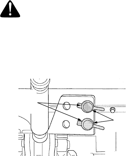
Check Links
Remove the pins and adjust the length of the check
links to limit, or increase, the side to side movement
of the lower links as suggested in the implement
owner’s manual.
WARNING: Keep the guard around the
PTO shaft in place at all times. Replace
the PTO shaft cap when the shaft is not in
use.
A
B
C
TOP LINK
HOLDER
Upper Hole
Middle Hole
Lower Hole
LEFT
LIFT
LINK
Check
Links
Check Link Pins
Jam Nut
Adjustment
Tube
29
USING REMOTE HYDRAULICS
The tractor is equipped with a remote hydraulic
system for powering hydraulically driven implements
that are approved for usage on the tractor.
WARNING: To avoid personal injury, stop
the tractor engine and relieve pressure
from the hydraulic system before
connecting or disconnecting lines. Do
not use your hand to check for leaks.
Connecting Implements
• Clean the hydraulic couplers on both the tractor
and implement.
• Remove the dust plugs and/or caps from the
couplers. See Figure 37.
Figure 37
• Insert the implement coupler into the tractor
hydraulic coupler.
• Pull slightly on the implement couplers to make
certain they are firmly connected to the tractor.
Disconnecting Implements
• Lower the implement to the ground to release
hydraulic pressure in the hoses.
• Relieve pressure by moving the hydraulic control
lever in each direction several times with the
engine shut off.
• Pull each implement hose coupler straight from
the hydraulic coupler to release it.
• Clean oil and dust from each coupler and replace
the dust plugs and/or caps.
Remote Control Valve Lever
Move the lever up or down and hold. This will raise or
lower the implement. The lever will return to neutral
when released.
IMPORTANT: Do not hold the lever in the "pull" or
"push" position once the remote cylinder has reached
the end of its stroke. Doing so will force oil through
the relief valve, and over a prolonged period cause
the hydraulic oil to overheat.
IMPORTANT: When using the tractor hydraulic
system to power a front loader, do not operate the
boom and bucket cylinders simultaneously.
TRACTOR WEIGHTING
When implements are installed on either the front or
rear of a tractor, the tractor’s normal balance is altered.
• As a rear mounted implement is raised to the
transport position, the balance point of the tractor
shifts rearward, which may result in a loss of
steering control and tractor stability.
• When a front mounted implement is raised, the
balance point shifts forward and may result in a
loss of traction and stability.
To counterbalance these weight shifts, weight should
be added to the tractor in the form of cast iron
weights or liquid ballast. However, only enough
weight should be added to obtain good traction, con-
trol, and stability. Excessive weight will unnecessarily
load down the tractor’s engine and transmission.
NOTE: When adding weight to the tractor, it may be
necessary to increase inflation pressure in the tires.
Front Weights
To counterbalance three point hitch mounted
equipment, weight should be added to the front of the
tractor. Add enough ballast to maintain steering
control and prevent tip over. Remove the weight
when it is not needed. Front weights are available at
your Cub Cadet dealer.
Follow the guidelines provided in the implement
Operator’s Manual to determine how much weight is
needed to counterbalance the equipment. If
guidelines are not available, ballast the tractor so that
a minimum of approximately 40% of the machine
weight is on the front wheels.
If necessary, contact your Cub Cadet dealer for help
in determining how much weight is needed for your
particular application.
Weighting the Rear of the Tractor
Add weight to the rear wheels if needed to improve
traction or for stability. The amount of rear ballast
should be matched to the job, and the ballast should
be removed when it is not needed. The most common
methods of adding weight are filling the rear wheels
with liquid ballast or mounting a rear weight box.
Liquid Ballast
Because special equipment and a familiarity with the
practice is required, only a qualified tire technician
should perform this procedure. Consult with your Cub
Cadet dealer about having liquid ballast added to
your tires, and for any special maintenance
instructions after the procedure is performed.
Rear Weight Box
Consult with your Cub Cadet dealer about available
rear weight boxes. Your dealer can help in
determining the positioning of the box and the amount
of weight needed for your particular application.
Auxiliary
Hydraulic
Couplers
(One Set)
Dust Cap
30
SECTION 3: ADJUSTMENTS
ADJUSTING THE SEAT
For the comfort of the operator, a single lever
adjustable seat is provided to set the fore to aft
position of the seat. Adjust the seat to the most
comfortable position that allows you to operate all
controls and pedals.
WARNING: Do not adjust the seat when
the tractor is moving, as this could cause
the operator to lose momentary control
of the tractor and result in an accident.
• To adjust the seat, pivot the seat adjustment
lever to the left and hold while repositioning the
seat to the desired position. See Figure 38.
Figure 38
• After repositioning the seat, release the lever to
lock the seat in position. Slide the seat either
slightly forward or rearward to assure it is locked
or until engagement of the lock is felt.
ADJUSTING FRONT WHEEL TOE-IN
The front wheel toe-in is set at the factory and should
maintain the proper setting. However, the toe-in
should be checked periodically and readjusted if
necessary.
CHECK THE TOE-IN AS FOLLOWS:
• Place the tractor on a level surface with the
wheels in the straight ahead position.
• Place an easily visible mark at the front and rear
center lines of both front tires, preferably at the
horizontal center line of the wheel.
• Measure and record the distance ‘A’ between the
two front marks. Then measure and record the
distance ‘B’ between the two rear marks. See
Figure 39.
Figure 39
• Distance ‘A’ should be .08" to .31" less than
distance ‘B’ if the toe-in is correct. If it is not,
adjust the toe-in.
READJUST THE TOE-IN AS FOLLOWS:
• Loosen the jam nuts at both ends of the tie rod.
Refer to Figure 39.
• Turn the tie rod in either direction to adjust its
length.
- Shorten the tie rod to increase distance ‘A’ and
decrease the toe-in.
- Lengthen the tie rod to decrease distance ‘A’
and increase the toe-in.
• Adjust the tie rod as necessary to obtain the
correct toe-in, then tighten the jam nuts.
ADJUSTING FRONT AXLE
Looseness or play in the front axle may cause serious
trembling of the front wheels and vibration of the
steering wheel. Check and adjust the front axle as
follows:
• Raise and support the front of the tractor so that
the front wheels are just off the ground.
• Check the front axle for any front to back play.
• If play is felt, loosen the jam nut on the adjusting
bolt in the center of the front axle support. See
Figure 40.
Figure 40
Pivot Lever
to Left
SEAT
ADJUSTMENT
LEVER
Slide Seat
A
B
JAM
NUT
JAM
NUT TIE
ROD
JAM NUT
ADJUSTING
BOLT
31
• Tighten the adjusting bolt as necessary to
remove the play from the front axle, then
retighten the jam nut.
• Lower the front of the tractor to the ground.
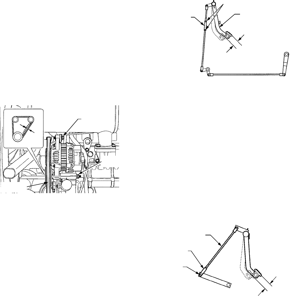
ADJUSTING THE FAN BELT TENSION
If the fan belt becomes loose, the engine may
overheat and/or the battery may not charge. Check
the belt tension and, if necessary, adjust as follows:
• With approximately 22 lbs. of pressure, depress
the backside of the belt at its center point
between the alternator and lower engine pulley.
The deflection of the belt should be
approximately 0.3 inches. See Figure 41.
Figure 41
• If adjustment is needed, loosen the nut on the
alternator mounting bolt and loosen the adjusting
bolt. See Figure 41.
• Pivot the alternator to acquire the correct belt
tension and re-tighten the adjusting screw and
mounting fasteners.
BRAKE ADJUSTMENT
Moderate brake pedal play, as measured at the end
of the pedals, ranges from 0.98 to 1.57 inches (25 to
40 mm). If the brake pedals need adjustment,
proceed as follows:
• Loosen the jam nuts from the turnbuckle on both
the left and right brake adjustment rods. See
Figure 42.
• Turn the turnbuckle on each rod until both the
right and left brake pedals are within the
acceptable range of play. See Figure 42.
• Tighten the jam nuts after adjusting the
turnbuckles.
• Interlock and depress both brake pedals and
check that the parking brake engages properly.
Figure 42
IMPORTANT: The brake pedals should be adjusted
in such a manner that the levels of the right-hand and
left-hand brake pedals are uniform. If they are not
uniform, the brakes may work excessively to one side
when the are depressed simultaneously.
CLUTCH ADJUSTMENT
Moderate clutch pedal play ranges from 1.57 to 1.96
inches (40 to 50 mm) as measured at the end of the
pedal. If it becomes difficult to disengage the clutch or
pedal play decreases, adjust the length of the clutch
rod. From inside the left side panel, remove the
internal cotter pin and clevis pin to disconnect the
clutch rod. If the clutch is difficult to disengage,
shorten the rod. If there is too little play in the clutch
pedal, lengthen the rod. See Figure 43.
Figure 43
IMPORTANT: Free travel of the clutch pedal is
governed by the clearance between the clutch’s
release thrust bearing and the release levers. This
clearance is set from 0.098 to 0.12 inches (2.5 to 3
mm) when the tractor is built, but this changes as the
tractor is used. If the pedal is used with no clearance,
it will result in the seizure of the release bearing or
wear of the facing. Therefore, be sure to check and
adjust at the intervals called for in the maintenance
schedule.
Loosen
Adjusting
Bolt
Loosen Mtg.
Bolt Nut
Depress
V-Belt
0.3 in.
Deflection
0.98-1.57 in.
Free Play
Loosen
Jam Nuts
Adjusting
Turnbuckle Brake Pedal
1.57 -1.96 in.
Free Play
Clutch Rod
Clevis Pin
Turn Clevis
to Adjust
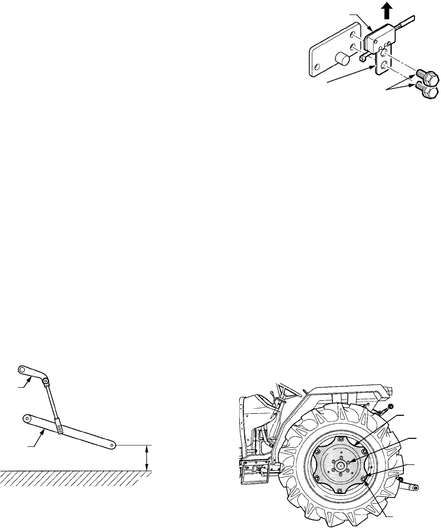
32
To Adjust
• Open the clutch access window which is located
on the right front of the clutch housing.
• Insert a 0.098 to 0.12 inch (2.5 to 3.0 mm) feeler
gauge between the release thrust bearing and
the release levers. Adjust the clearance by
adjusting the length of the clutch rod.
- Lengthen the rod if the clearance is wider than
the specification.
- Shorten the rod if the clearance is less than the
specification.
• Depress the clutch pedal and check to make
certain that the free travel at the tip of the pedal is
1.57 to 1.96 inches (40 to 50 mm).
• With the clutch pedal fully depressed, confirm
that there is adequate gap between the clutch rod
and the safety start switch.
IMPORTANT: When adjusting the clutch pedal free
travel, always use measuring devices rather than
visually estimating distances.
ADJUSTING THE MICRO SWITCH HEIGHT
The PTO micro switch, located on the right fender
aside the position control lever, is initially set so that
the PTO will disengage when the 3-point hitch lower
links are raised to approximately 23.6 to 26 inches.
See Figure 44.
Figure 44
If your application requires the PTO to run with the
lower links at a height above 23.6 to 26 inches, the
micro switch position can be adjusted as follows:
• Loosen the screws securing the micro switch
mounting bracket. Refer to Figure 45.
Figure 45
• Raise the switch slightly and recheck the position
of the lower links when the PTO shuts off.
• If necessary, repeat the above step until the PTO
shut-off height of the lower links is adequate for
your application. The switch can be adjusted so
that the lower links can be raised to approxi-
mately 35.8 inches before the PTO will be
disengaged.
ADJUSTING WHEEL TREAD
When operating the tractor in the field, it is sometimes
necessary to change the rear wheel tread to a
narrower position to avoid plant rows, or to widen the
tread to improve stability when operating on slopes.
The rear wheel tread width can be adjusted to any of
6 different positions ranging from 46.4 to 58.6 inches
by changing the position of the wheel disc relative to
the rim mounting brackets and the rear axle.
Figure 46
IMPORTANT: The front wheel tread width cannot be
adjusted. Attempting to do so will cause damage to
the tractor. If removed, torque front wheel lug nuts to
57.2 - 66.5 ft. lbs.
23.6 - 26.0 in.
Shut-off Height
Lower Link
Lift Arm
Mounting Bracket Mtg. Screws
Micro Switch
Wheel Disc
Lug Nut
Rim Mtg.
Mtg. Bolt
Bracket
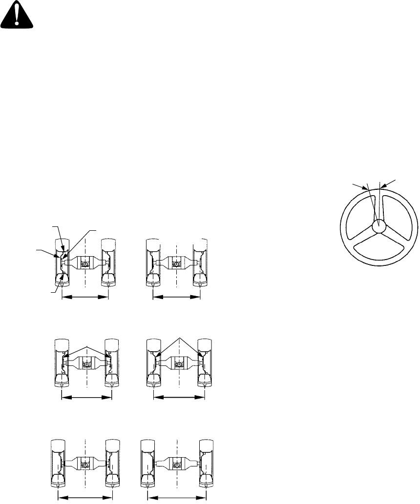
33
To Adjust
WARNING: Never operate the tractor with
loose wheel assembly fasteners. Always
tighten the fasteners to the specified
torque, and frequently check that they
are tight.
IMPORTANT: When changing the tread width of the
rear wheels, you must pay attention to the direction of
the tire’s tread design and make certain to maintain
that direction. To do this, it will at times be necessary
to switch wheel assemblies from one side of the
tractor to the other.
• Raise and support the rear of the tractor.
• Adjust the tread widths as shown by changing
the mounting relationship of the wheel disc to the
rim mounting brackets and/or the relationship of
dish of the wheel disc to the axle. See Figure 47.
Figure 47
• Torque the nuts to 145-165 ft. lbs. (196-226 N
•
m).
• Raise the rear of the tractor, remove the
supports, and lower the tractor to the ground.
CHECKING STEERING WHEEL
If it is difficult to drive the tractor in a straight line,
check the play in the steering wheel. Acceptable
steering wheel play is 0.8 to 2.0 inches (24 to 50 mm)
as measured at the outer circumference of the
steering wheel. If your steering wheel free play
exceeds the acceptable range, contact your Cub
Cadet dealer to have the tractor inspected.
Figure 48
58.6"
54.3"
50.7" 51.3"
46.4" 47.0"
Standard
Rim Mtg.
Bracket
Rim Mtg.
Bracket
Wheel
Disc
Rear Axle
Disc - Dish
Inward
Disc - Dish
Outward
Acceptable Steering
Wheel Play
0.8 - 2.0 in.

34
SECTION 4: MAINTENANCE
The service life and reliability of any machine
depends upon the care it is given. Proper lubrication
and maintenance is a vital part of that care. Using the
Lubrication and Maintenance Chart as a guide, moni-
tor the hourmeter on the instrument panel to ensure
the required maintenance procedures are performed.
The maintenance schedule reflects the minimal
requirements to maintain the equipment. More fre-
quent inspections and maintenance is preferable.
Make certain that all lubrication fittings are installed
and functioning. Wipe away all old grease and dirt
from the lube fittings to prevent foreign materials from
entering as the new grease is applied. Use a
pressure lubricating gun to force in new grease. Apply
pressure until clean grease emerges from the
lubrication point.
Miscellaneous working parts not provided with
lubrication fittings should be oiled regularly with a
good grade of lubricating oil.
Lubricant is cheap. Use plenty of it. Worn parts can
be expensive to replace.
Store your supply of lubricating grease and oil in
clean, covered containers to protect them from dust
and dirt. Keep the lubricating gun nozzle clean.
LUBRICATION TABLE
Application Type of
Lubricant
General Information
Capacity API
Classifi-
cation
SAE
Viscosity Description
Engine Engine Oil Approx.
7.6 Qts
w/Filter
CC
or
CD 15W-40 Cub Cadet
737-3039 (1Qt.)
Transmission
and
Hydraulic
System
Hydraulic
Transmission
Fluid
Approx.
36 Qts.
(9.0 Gal.)
Alternate Oils Shown Below
Shell — Donax-TD
or
Donax-TM
Mobil — Mobil Fluid 423
Exxon — Torque Fluid 56
Front Wheel
Drive Axle Gear Lube Approx.
8.8 Qts.
(2.2 Gal.)
SAE80 or SAE90
Gear Oil
Lube
Fittings Grease As Needed Use Cub Cadet
251H EP Grease
737-3034 (14.5 Oz. Cartridge)
Radiator
and
Overflow
Reservoir
Antifreeze
Approx.
2.4 Gal.
Use High Quality Permanent Type Antifreeze
(Ethylene Glycol with corrosion and rust
inhibitor chemicals)
Coolant Mixture Ratio
Distilled Water 50% : Antifreeze 50%

35
LUBRICATION AND MAINTENANCE CHART
†First 50 hours
No. Operation to
be Performed
Service Intervals
Before
each use
50 Hours
100 Hours
150 Hours
200 Hours
250 Hours
300 Hours
350 Hours
400 Hours
450 Hours
500 Hours
550 Hours
600 Hours
1 Year
2 Years
1 Check Engine Oil Level
•
2 Check and Clean Air Cleaner
•
3 Check Engine Coolant Level
•
4 Check Transmission Oil Level
•
5 Check and Clean Radiator
Screen
•
6 Check Oil Level of Front Axle
and Final Drive Gear Cases
•
7 Check and Clean Fuel Filter
••••••
8 Change Engine Oil and Replace
Oil Filter †
••••••
9 Change Oil in Front Axle and
Final Drive Cases (both sides) †
••
10 Replace Transmission and
Hydraulic Oil and Oil Filter †
••
11 Replace Air Cleaner Element
••••••
12 Change Engine Coolant
•
13 Replace Fuel Filter Element
•
14 Check Oil Pressure Lines and
Fuel Lines for Tightness
••••••••••••
15 Check Radiator Hoses for
Tightness
••••
16 Check Air Cleaner Hose for
Tightness
••
17 Check Fan Belt Tension
••••••
18 Replace Fuel Line
•
19 Replace Radiator Hoses
•
20 Replace Hydraulic Hose
•
21 Replace Hydraulic Couplers
•
21 Drain Clutch Housing
••••••••••••
22 Grease Lubrication Points
••••••••••••
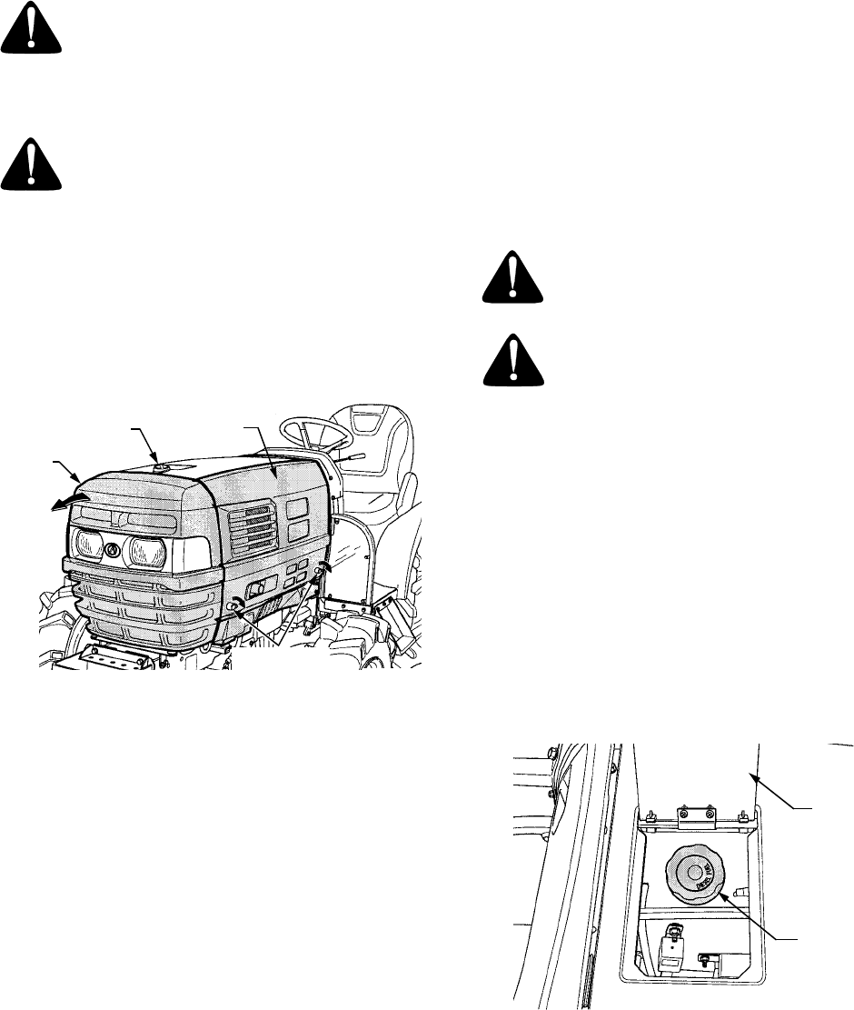
36
WARNING: Use care when servicing any
component in the engine area. If the
engine has recently been operated,
components will be hot and could cause
burns. Allow the engine to cool before
servicing.
WARNING: Before servicing the engine,
place the tractor on a level surface, stop
the engine, engage the parking brake,
and remove the key from the ignition
switch.
ACCESSING THE ENGINE COMPARTMENT
Opening the Front Grille
To open the front grille, turn the latch knob at the front
of the hood and pivot the top of the grille forward. See
Figure 49.
Figure 49
To close the grille, pivot the grille upward and align its
latch bracket with the slot in the hood. Push the grille
rearward until it locks.
Removing the Side Panels
• Locate the two latch knobs at the bottom corners
of the side panel and turn the handle of the knobs
downward. Refer to Figure 49.
• Pull the bottom of the side panels slightly outward
and securely grasp the panel while lifting it
straight upward to remove.
Installing the Side Panels
• Position the side panel and lower its top flange
into the slot of the hood.
• Pivot the bottom of the side panel inward while
making certain the pins of the latch knobs align
with the latch springs on the tractor.
• Press the latch knobs inward and turn the handle
upward to lock the side panel in place.
NOTE: It may be necessary to firmly push the latch
knobs inward to lock in the latch springs.
FUEL SYSTEM
Checking and Refilling
WARNING: Stop the engine before
adding fuel. Keep away from sparks and
flames.
WARNING: Never fill the fuel tank to the
top of the filler neck. Expansion could
result in overflow through the cap vents,
allowing fuel to come in contact with hot
surfaces, which could cause a fire.
IMPORTANT: If the fuel tank becomes empty, air is
admitted to the fuel system. If air enters the fuel
system, it must be eliminated before the engine can
be started.
When filling the fuel tank, always use a strainer to
prevent contaminants from entering the fuel system
and possibly causing fuel injection pump
contamination.
• Check the fuel level before each use. Take care
that the fuel tank is not allowed to become empty.
See Figure 50.
Figure 50
Turn Grille
Latch Knob
Grille
Side Panel
Side Panel
Latch Knob
ACCESS
DOOR
FUEL CAP
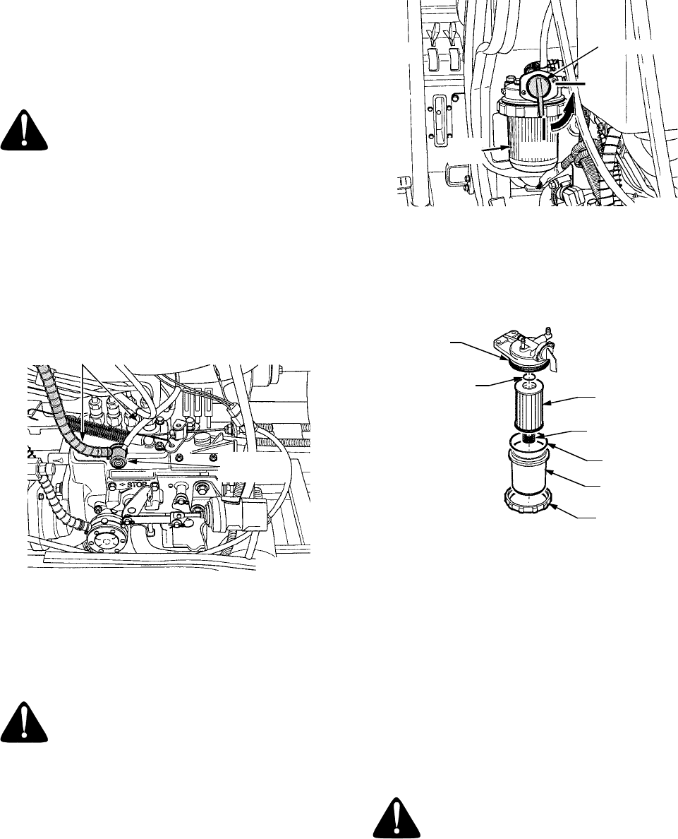
37
• Use No. 2 diesel fuel. Use No. 1 diesel fuel if the
temperature is below 15° F (-10°C).
• The fuel tank capacity is approximately 10.6 gal.
Do not overfill.
Bleeding the Fuel System
WARNING: Do not bleed the fuel system
when the engine is hot.
Air must be bled from the fuel system when the fuel
filter or fuel lines are removed; the fuel tank is
completely emptied; or the tractor has not been used
for a long period of time.
• Fill the fuel tank with No. 2 diesel fuel and make
certain the shut-off valve on the fuel filter is open.
• Loosen the air vent cock on the injection pump
two or three turns by hand, then start to turn the
engine over. See Figure 51.
Figure 51
• When there are no more air bubbles in the fuel
line, tighten the air vent cock.
Servicing the Fuel Filter
WARNING: When servicing the fuel fil-
ter element, take all precautions to
prevent dust or dirt from entering the
fuel system. Contaminants will cause
premature wear and/or malfunction of
the injection pump and injection
nozzles.
The fuel filter should be cleaned after every 100
hours of operation, and replaced after every 400
hours.
• Make certain the area is free of dust and dirt.
• Close the shut-off valve on the fuel filter. See
Figure 52.
Figure 52
• Unscrew the retaining ring and remove the ring
and fuel filter bowl from the filter. Use care not to
lose the O-ring and spring. See Figure 53.
Figure 53
• Flush the bowl out with clean diesel fuel.
• Remove the element and either dip it into a con-
tainer of clean diesel fuel to clean it, or replace it
with a new element.
• Install the new, or cleaned, element onto the fil-
ter body.
• Install the filter bowl and retaining ring over the
element, and tighten the retaining ring to secure.
• Bleed the air from the fuel system using the air vent
cock on the injection pump. Refer to Figure 51.
Checking the Fuel Lines
WARNING: The fuel line hoses are
subject to wear and natural aging. A
leaking fuel line may allow fuel to come
into contact with sources of ignition, and
could cause a fire.
The condition of the fuel line hoses and clamps
should be checked every 100 hours or six months
(whichever occurs first), and they should be replaced
every two years. Refer to Figure 51.
Fuel Line
Turn Air
Vent Cock
Close
Shut-off Valve
Open
Fuel
Filter
Retaining Ring
Bowl
O-ring
Spring
Filter Element
O-ring
Filter Body
(DD-84612-4316-0)
38
• Stop the engine before checking the fuel line
hoses and clamps.
• Check that the fuel line hose clamps are snugly
securing the hoses to their respective fittings.
Replace any damaged clamps.
• Check the fuel hoses for wear or deterioration,
and any damaged hoses should be replace
immediately.
• After replacing a fuel line, it will be necessary to
bleed air from the fuel system before starting the
engine.
IMPORTANT: When servicing the fuel line hoses and
clamps, care should be taken to prevent dirt or dust
from entering the fuel system. If replacing a fuel line
hose, inspect the new hose to make certain no dirt or
debris has entered the hose.
ENGINE OIL AND OIL FILTER
Checking the Engine Oil Level
Check the engine oil level before each use. If
checking the oil level after running the engine, wait at
least 5 minutes after stopping the engine to get an
accurate reading.
• Remove the left side panel.
• Clean the area around the dipstick to prevent
debris from entering the crankcase; then with-
draw the dipstick from the engine and wipe clean.
See Figure 54.
Figure 54
• Fully re-insert the dipstick into the engine.
• Withdraw the dipstick again, and check that the
oil level is between the upper and lower marks on
the dipstick. Always keep the oil level between
the full and add marks on the dipstick.
• Reinsert the dipstick into the engine and press
firmly into place.
Adding Engine Oil
If the oil level is low, add enough oil to bring the level
up to the full mark on the dipstick. Do not overfill the
crankcase. Refer to the LUBRICATION TABLE for
the proper type of oil to add to the crankcase. When
possible, maintain the brand and viscosity of oil
previously used to service the engine.
• Place the tractor on a level surface and engage
the parking brake. Stop the tractor engine and
remove the ignition key.
• Clean the area around the oil filler cap to prevent
debris from entering the crankcase.
Figure 55
• Turn the oil filler cap counterclockwise to unscrew
from the rocker arm cover.
• SLOWLY pour oil into the crankcase until the oil
level reaches the “FULL” mark on the dipstick.
• Insert the oil fill cap into the rocker arm cover and
turn clockwise until fully tightened. Reinsert the
dipstick into the engine and push firmly into
place.
IMPORTANT: The oil fill cap and dipstick must
always be installed securely in place when the engine
is running. Severe engine damage could result from
failure to do so.
Operating
Range
Dipstick
Oil Fill Cap
Rocker Arm
Cover
39
Changing Engine Oil and Filter
The engine oil and oil filter (located on the right/front
of the engine) should be changed after the first 50
hours of operation, then at 100 hours and every 100
hours thereafter. Refer to the LUBRICATION TABLE
for the quantity and type of oil needed.
WARNING: Because the engine is run
prior to draining the oil, the engine may
be hot. Use caution to avoid burning
yourself on engine surfaces.
Run the engine for a few minutes to allow the oil in
the crankcase to warm up. Warm oil will flow more
freely and carry away more engine impurities. Use
care to avoid burns from hot oil. While the engine oil
is warm, proceed as follows:
• Place the tractor on a level surface and engage
the parking brake. Stop the tractor engine and
remove the ignition key.
• Clean around the base of the oil filter, the oil filler
cap, and the dipstick to prevent debris from
entering the crankcase.
• Remove the dipstick and oil fill cap from the
engine. Refer to Figure 54 and Figure 55.
• Locate the engine drain plugs on the bottom of
the engine. Place a suitable container below the
drain plugs to collect the old oil. See Figure 56.
•
Figure 56
• Turn the drain plugs counter-clockwise to remove
from the engine.
• Allow the old oil to completely drain from the
engine crankcase into the container below.
• Move the drain pan beneath the filter, then
remove the filter by turning it counterclockwise
using a filter wrench to loosen. See Figure 57.
Figure 57
• Reinstall the drain plugs in the engine and clean
up any residual oil.
• Apply a light coating of clean oil on the gasket of
the new oil filter. Thread the filter onto the engine
and tighten by hand.
• Refill the crankcase to the "FULL" mark on the
dipstick with the appropriate type oil.
• Reinstall the oil fill cap and dipstick.
• Start and run the engine for a few minutes to
check that the engine oil pressure light goes out
and to circulate oil throughout the engine. Stop
the engine and check for leaks at the oil filter and
drain plug.
• Wait 3 minutes and re-check the oil level. If
needed, add oil to bring the oil level up to the
"FULL" mark.
WARNING: Never overfill the engine
crankcase. For best results, fill to the
“FULL” mark on the dipstick as opposed
to adding a given quantity of oil. Always
check the level on the dipstick before
adding more oil.
Dispose of used oil in an environmentally
safe manner. If necessary, contact your area
EPA office for proper disposal procedures
and recycling center locations.
IMPORTANT: The oil fill cap and dipstick must
always be installed securely in place when the engine
is running. Severe engine damage could result from
failure to do so.
Oil Drain
Plugs
Front Wheel Drive Shaft
Oil Filter
(DD-E6201-32443)
40
TRANSMISSION OIL AND OIL FILTER
Checking the Transmission Oil Level
Check the hydro transmission/hydraulic system oil
level before each use. Check the oil level only while
the engine is stopped and the tractor is standing on a
level surface.
• Locate the transmission dipstick on the rear of
the transmission at the back of the tractor. See
Figure 58.
Figure 58
• Clean the area around the dipstick to prevent
debris from entering the transmission; then with-
draw the dipstick from the transmission and wipe
clean.
• Fully re-insert the dipstick into the transmission.
• Withdraw the dipstick again, and check the oil
level. Always keep the oil level between the full
and add marks on the dipstick.
• If the oil level is low, refer to the LUBRICATION
TABLE for the proper type and quantity of oil to
add to the transmission.
• Clean the area around the breather cap and fill
tube on the back of the transmission to prevent
debris from entering the transmission . Then turn
the cap counterclockwise to unscrew from the oil
fill tube. Refer to Figure 58.
• Slowly pour transmission oil into the fill tube while
frequently checking the oil level with the dipstick.
Add only enough oil to bring the oil level up to the
full mark on the dipstick.
• Screw the breather cap into the fill tube, and
reinsert the dipstick into the transmission and
press firmly into place.
Changing the Transmission Oil and Filter
The oil in the transmission case is also used for the
hydraulic system. The transmission/hydraulic oil and
the oil filter (located on right side of tractor) should be
changed after the first 50 hours of operation, then at
300 hours and every 300 hours thereafter. Refer to
the LUBRICATION TABLE for the quantity and type
of oil needed.
• Clean the area around the transmission dipstick
and breather cap to prevent debris from entering
the transmission. Refer to Figure 58.
• Locate the drain plug on the bottom of the
transmission. Place a suitable container below
the drain plug to collect the old oil. See Figure 59.
Figure 59
• Remove the dipstick and breather cap from the
transmission.
• Turn the drain plug counter-clockwise to remove
from the transmission, and allow the old oil to
completely drain from the transmission. NOTE:
The capacity of the transmission is approximately
9 gallons (36 qts.), so it may be necessary to
drain the transmission in stages to capture the
used oil and/or to ease emptying the drain pan.
Dipstick
Breather/
Fill Tube
Fill Cap
Transmission
Drain Plug
41
• Move the drain pan beneath the filter, then
remove the filter by turning it counterclockwise
using a filter wrench to loosen. See Figure 60.
Figure 60
• Use a clean rag to clean the metal surface of the
filter base where the filter gasket makes contact.
• Reinstall the drain plug in the transmission and
clean up any residual oil.
• Apply a light coating of clean oil on the oil filter
gasket and on the sealing surface of the base.
Install the filter by turning it clockwise, by hand,
until the gasket contacts the filter base; then
tighten the filter an additional 1/2 to 3/4 turn.
• Slowly pour transmission oil into the fill tube while
periodically checking the oil level with the dip-
stick. Fill the transmission to the full mark on the
dipstick.
• Screw the breather cap into the fill tube and
reinsert the dipstick into the transmission and
press firmly into place.
• Start the engine and run at low to mid throttle for
approximately 5 minutes while actuating the
hydraulics (e.g. power steering and hydraulic lift).
IMPORTANT: Do not drive the tractor immediately
after changing the transmission oil and filter. Run the
engine for 5 minutes to prevent damage to the
transmission and/or hydraulic system.
NOTE: If hydraulically driven equipment, such as a
front loader, is installed on the tractor after the first 50
hours of operation, it is recommended that the filter
again be changed after the first 50 hours of operation
of that equipment.
Dispose of used oil in an environmentally
safe manner. If necessary, contact your area
EPA office for proper disposal procedures
and recycling center locations.
SERVICING THE FRONT AXLE
Check the oil level in the front axle frequently.
Change the oil in the front axle after the first 50 hours
of operation, then at 300 hours and every 300 hours
thereafter.
Checking the Front Axle Oil Lever
To check the front axle oil level, a viewing glass is pro-
vided in the axle. The oil level should be approximately
half way up in the viewing glass. See Figure 61.
Figure 61
Adding Front Axle Oil
If the oil level is low, refer to the LUBRICATION
TABLE for the proper type and quantity of oil to add
to the front axle. Add oil through the oil fill port on top
of the axle. Refer to Figure 61.
Changing the Front Axle Oil
• After cleaning the area, remove the oil fill plug
from the top of the axle. Refer to Figure 61
• Place a suitable container below the drain plugs,
then remove the plugs from the center of the front
axle and the final drives inside both wheels. See
Figure 62
Figure 62
• Replace the drain plugs and slowly fill the front
axle through the fill port until the oil level is
approximately half way up in the viewing glass.
Transmission Oil Filter
(DD-T4620-38032)
Fill Plug
Oil Level
Viewing Glass
Drain Plug
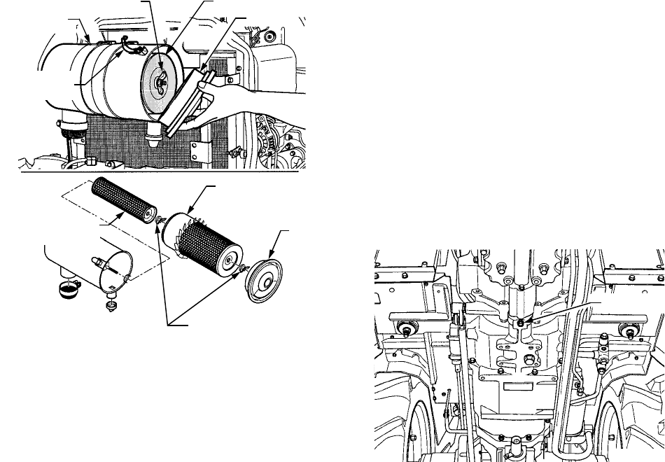
42
SERVICING THE AIR CLEANER
Check the air cleaner dust cup and element before
each use. Clean the dust out of the cup and blow off
the element weekly. Replace the element after every
100 hours of operation.
NOTE: The air cleaner uses a dry element, never
apply oil.
• Unclip the two retainers to remove the cup and
wipe out any build-up of dust. See Figure 63.
Figure 63
• Remove the wingnut and carefully withdraw the
filter element from the housing. See Figure 63.
• To clean the element, use clean dry compressed
air on the inside of the element. Air pressure at
the nozzle must not exceed 29 PSI and the
nozzle must be held a reasonable distance from
the element.
• Remove the second wingnut and carefully
withdraw the secondary filter element from the
housing. Gently blow or brush any dirt from the
element.
• Using care not to damage the elements, insert
the new, or cleaned, elements into the housing
and secure each with a wingnut.
• Install the cup and secure with the two retainers.
IMPORTANT: The air cleaner will only fulfill its
function if correctly and regularly maintained. A poorly
maintained air cleaner will mean loss of power,
excessive fuel consumption and a reduction in engine
life.
DRAINING THE CLUTCH HOUSING
The clutch housing should be checked and ,if
necessary, drained of any water after every 50 hours
of operation. The clutch housing should also be
checked if the tractor has been operated in inclement
weather or in wet fields with standing water, or has
been hosed off.
Remove the drain plug in the bottom of the clutch
housing to drain. If water is drained, allow the inside
of the clutch housing to dry. See Figure 64.
Figure 64
Filter Element
Wing Nut
Cap
Air Cleaner
Housing
Retainer
Clip
Filter Element
Wing Nut
Cap
(DD-E6300-11081)
Filter Element
(DD-E6300-11091)
Drain Plug
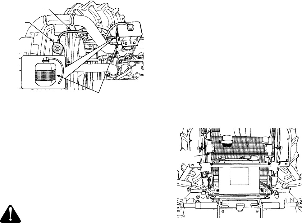
43
SERVICING THE COOLING SYSTEM
Before each use, the engine coolant level in the
overflow reservoir should be checked to ensure it is
within the operating range. Engine coolant absorbs
heat from the engine and transfers the heat to the air
flowing through the radiator. If the coolant level
becomes low, the engine may overheat and could
cause severe damage to the engine.
Use a permanent type antifreeze containing corrosion
and rust inhibitors. Dilute the antifreeze with water at a
1:1 ratio to mix the coolant solution (50% antifreeze :
50% water).
Checking and Adding Coolant
Check the coolant level in the overflow reservoir
before each use. See Figure 65.
Figure 65
If the level is below the lower line on the reservoir,
add coolant to the reservoir as follows:
• If coolant level is low due to evaporation, refill
with water only.
• If coolant level is low due to leakage, refill with
the appropriate mixture of anti freeze and water.
If the reservoir is empty, the coolant level in the
radiator should be checked before operating the
tractor. Proceed as follows:
WARNING: It is dangerous to remove the
radiator cap when the system is hot.
Allow the system to cool before
removing the radiator cap.
• Locate the radiator cap beneath the access door
at the forward end of the hood. Turn the radiator
cap counterclockwise to the first stop to release
any pressure. Refer to Figure 65.
• Push downward on the cap and turn counter-
clockwise until the cap stops then lift cap off.
• Slowly pour coolant mixture into the filler neck
until the level reaches the bottom of the filler neck
overflow flange.
• Wait a few minutes to allow as much air as
possible to escape through the filler neck, then
reinstall the radiator cap.
• Fill the overflow reservoir to the "FULL" mark.
• Start the engine and allow it to run for a short
period. Stop the engine.
• Recheck the coolant level in the overflow
reservoir and refill as needed. Reinstall the
reservoir cap.
Checking and Cleaning Radiator Screen
The radiator screen is designed to catch debris, and
prevent it from clogging the air passages between the
radiator cooling fins. See Figure 66.
Check the radiator screen daily and blow off any
minor accumulations of debris using compressed air
directed from the fan shroud side of the radiator.
NOTE: During certain times of year it may be
necessary to clean the screen more often.
If the screen becomes extremely dirty, remove the
wing bolt and slide the screen out from the right side
of the tractor. Flush the screen with water. Reinsert
the screen and secure with the wing nut.
Figure 66
Overflow
Overflow Tube
Radiator
Reservoir
Cap
Radiator
Screen
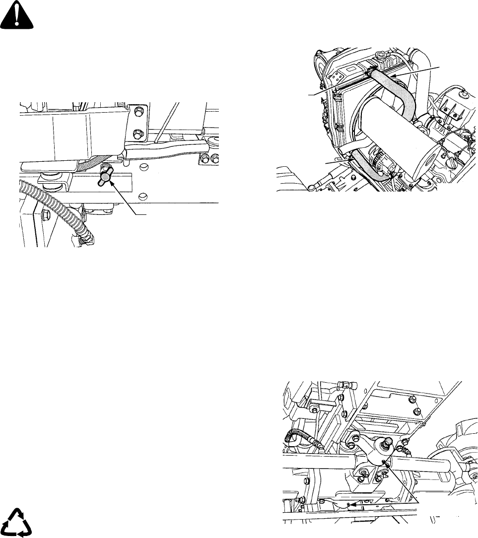
44
Changing the Coolant
The anti freeze and water coolant solution should be
changed every year. The cooling system capacity is
approximately 2.4 gallons.
WARNING: It is dangerous to remove the
radiator cap when the system is hot.
Allow the system to cool before
removing the radiator cap.
• Locate the radiator drain cock on the right side od
the front axle frame. Place a suitable container
beneath the drain cock. See Figure 67.
Figure 67
• Open the radiator drain cock and remove the
radiator cap. The radiator cap must be removed
to completely drain the radiator.
• Close the radiator drain cock.
• Slowly pour coolant mixture into the filler neck of
the radiator until the level reaches the bottom of
the filler neck overflow flange.
• Wait a few minutes to allow as much air as
possible to escape through the filler neck, then
reinstall the radiator cap.
• Fill the overflow reservoir to the "FULL" mark.
• Start the engine and allow it to run for a short
period. Stop the engine.
• Recheck the coolant level in the overflow
reservoir and refill as needed. Reinstall the
reservoir cap.
Dispose of used coolant in an environmen-
tally safe manner. If necessary, contact your
area EPA office for proper disposal proce-
dures and recycling center locations.
Checking the Radiator Hoses
Check the condition of the radiator hoses and the
tightness of the hose clamps every 150 hours of
operation. Replace a damaged hose and tighten the
hose clamps if loose. See Figure 68.
It is recommended that the hoses and, if necessary,
the hose clamps be changed every two years.
Figure 68
LUBRICATING THE TRACTOR
After every 50 hours of operation apply Cub Cadet
251HEP grease (or equivalent) to all lube fittings.
Wipe away all old grease and dirt from the lube
fittings to prevent foreign materials from entering as
the new grease is applied. Use a pressure lubricating
gun to force new grease through the lube fittings of
the following tractor components:
• Front axle pivot brackets (front and back). See
Figure 69.
Figure 69
Radiator
Drain Cock
Upper
Radiator
Hose
Lower
Radiator
Hose
Hose
Clamp
Front Axle
Lube Fitting
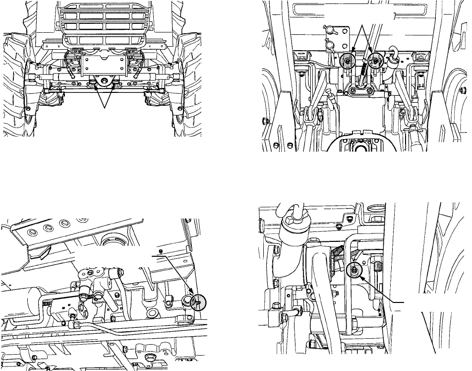
45
• Steering cylinders. See Figure 70.
Figure 70
• Brake pedal shaft (both sides). See Figure 71.
Figure 71
• 3 Point top link holder (each side). See Figure 72.
Figure 72
• Position lever support housing. See Figure 73.
Figure 73
Periodically apply grease to both seat slides and to
the threads of the right hand lift link to lubricate and
prevent rust.
Steering Cylinder
Lube Fitting
Brake Pedal Shaft
Lube Fitting
Top Link Holder
Lube Fitting
Support Housing
Lube Fitting
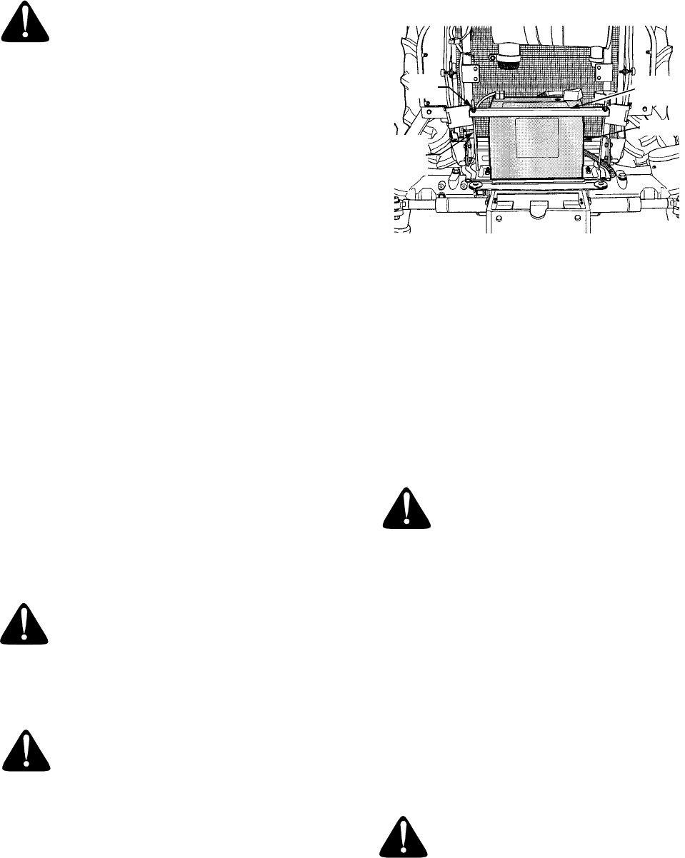
46
SERVICING THE BATTERY
General Battery Information
WARNING:
• Battery posts, terminals and related accessories
contain lead and lead compounds. Wash hands
after handling.
• Battery acid must be handled with great care, as
contact with it can burn and blister the skin. It is
advisable to wear protective clothing (goggles,
rubber gloves and apron) when working with acid.
• Should battery acid accidentally splatter into the
eyes or onto the skin, rinse the affected area
immediately with clean cold water. If there is any
further discomfort, seek prompt medical attention.
• If acid spills on clothing, first dilute it with clean
water, then neutralize with a solution of ammonia/
water or baking soda/water.
• Because battery acid is corrosive, do not pour it
into any sink or drain. Before discarding an empty
electrolyte container, rinse it thoroughly with a
neutralizing solution.
• NEVER connect (or disconnect) battery charger
clips to the battery while the charger is turned on,
as it can cause sparks.
• Keep all sources of ignition (cigarettes, matches,
lighters) away from the battery. The hydrogen
gas generated during charging can be
combustible.
• As a further precaution, only charge the battery in
a well ventilated area.
• Always shield eyes and protect skin and clothing
when working near batteries.
WARNING: Batteries contain sulfuric
acid and may emit explosive gases. Use
extreme caution when handling batter-
ies. Keep batteries out of the reach of
children.
Battery Removal
WARNING: Battery posts, terminals and
related accessories contain lead and
lead compounds. Wash hands after
handling.
The battery is located at the front of the tractor behind
the grill, just forward of the radiator.
To remove the battery:
• Open the grill as described previously.
• Remove the two nuts and the battery hold-down
strap from the battery hold-down rods. See
Figure 74.
Figure 74
• Loosen the cable clamp of the negative battery
lead, then lift the negative cable off the negative
battery post. Move the cable away from the nega-
tive battery post.
• Repeat the above procedure to remove the cable
from the positive battery post.
• Carefully lift the battery out of the tractor.
Install the battery by repeating the above steps in the
reverse order.
WARNING: Always connect the positive
lead to the battery before connecting the
negative lead.
Battery Maintenance
• Check the battery occasionally to make certain it
is tightly fixed in its battery tray.
• Make certain the battery vent caps are tightened
securely in the vent holes.
• Spray the terminals and exposed wire with a
battery terminal sealer, or coat the terminals with
a thin coat of grease or petroleum jelly, to protect
against corrosion.
• The battery should be kept clean. Any deposits of
acid should be neutralized with baking soda and
water. Be careful not to get this solution in the
cells.
WARNING: Never remove any of the
battery vent caps while the engine is
running.
Hold
Down
Rod
Hex
Nut
Battery
Battery Hold
Down Strap
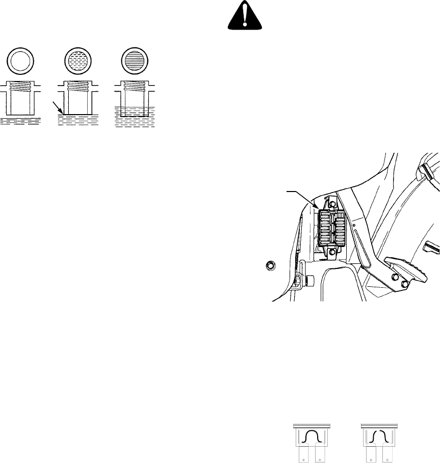
47
• Maintain the battery electrolyte level in each cell.
Keep each cell filled to the bottom of the ring in
each vent hole. Fill with distilled water if
necessary. See Figure 75.
Figure 75
Re-charging the Battery
• Remove the vent caps from the battery. Check
each cell and fill to the bottom of the ring in each
vent hole with distilled water.
• Connect the positive lead from the charger to the
positive battery terminal, then the negative lead
to the negative terminal.
• Avoid quick charging as it may shorten the
lifetime of the battery. Use a slow charge rate to
charge the battery. The charging rate should be
between 5 and 7 amps.
• Check the electrolyte level two hours after
charging is completed and correct it, if necessary,
by adding distilled water.
Battery Storage
• When storing the tractor for extended periods,
disconnect the battery cables. Removing the
battery from the unit is recommended.
• All batteries discharge during storage. Keep the
exterior of the battery clean, especially the top. A
dirty battery will discharge more rapidly.
• The battery must be stored with a full charge. As
the battery discharges, the electrolyte is weak-
ened and will freeze at a higher temperature.
• Recharge the battery every month in hot weather
seasons or every two months in cold seasons.
SERVICING THE ELECTRICAL SYSTEM FUSES
Fuse Box
WARNING: Always replace blow fuses
with fuses of the same rating. Using
incorrect fuses could cause damage to
the tractors wire harnesses. Never use a
wire, coin, or any other conductive
material to replace a fuse.
If one of the electrical circuits does not work, check
the appropriate fuses first.
• Locate the fuse box on the lower left side of the
pedestal near the clutch pedal. See Figure 76.
Figure 76
• Remove the cover from the fuse box.
• Carefully pull out the appropriate fuse(s) and
check for a blown fuse. Replace with the same
size fuse. See Figure 77 and Figure 78.
Figure 77
Battery Electrolyte Level
Deficient Correct Excessive
To
Ring
Fuse Box
GOOD BAD
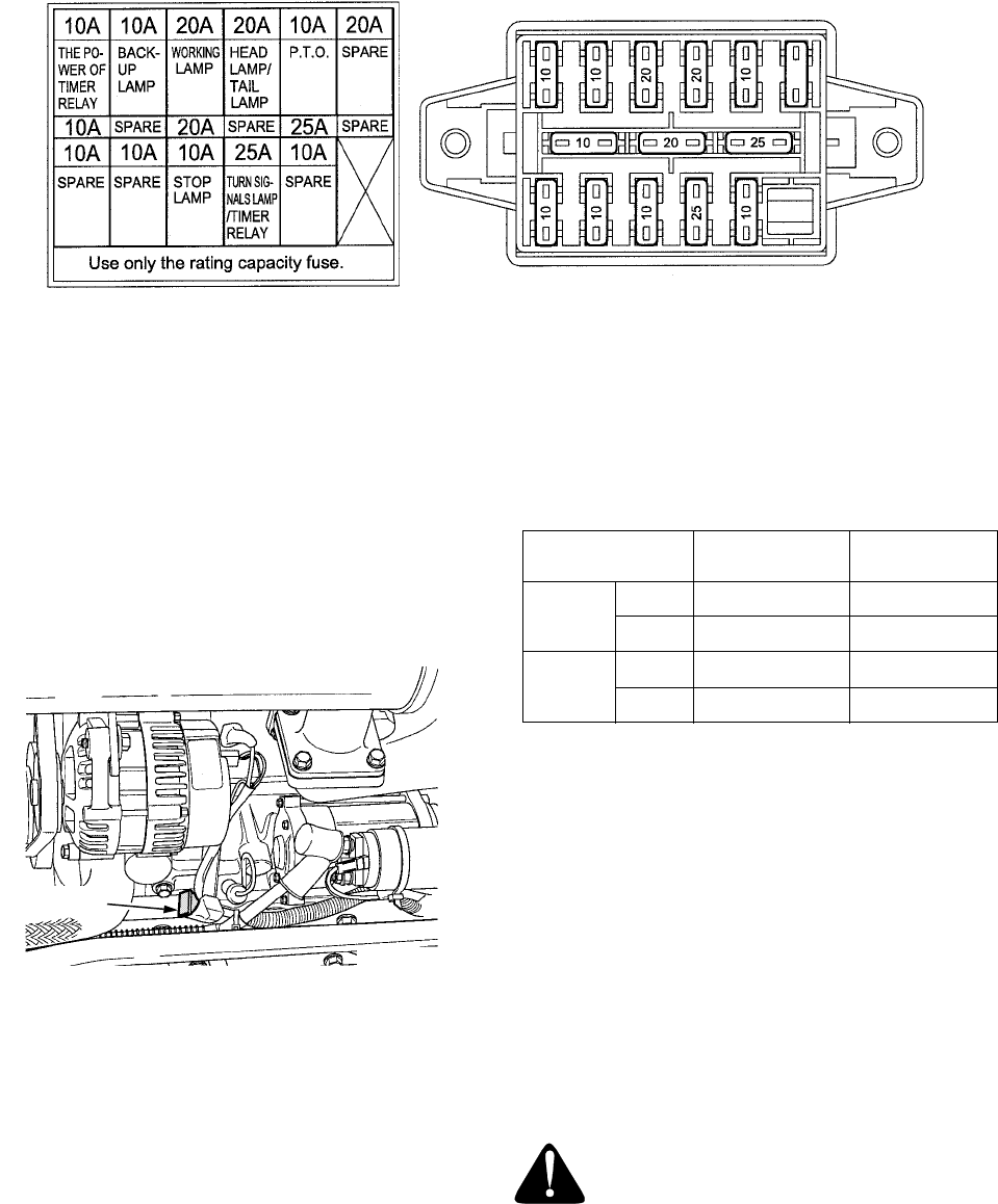
48
Figure 78
• If a fuse continually fails, have the electrical
harnesses check by your Cub Cadet dealer or a
qualified electrician.
Main Slow Blow Fuse
• Locate the slow blow fuse in the wire harness
behind the left side panel. See Figure 79.
Figure 79
• Remove the coupling and replace the old slow
blow fuse with a new one.
IMPORTANT: The slow blow fuse serves to protect
the electrical system. If the fuse blows, have the
tractor electrical system checked to find the cause.
Never substitute a different fuse.
TIRE MAINTENANCE
Check the tire air pressure before each use. Keep the
tires inflated to the recommended pressures.
Improper inflation will shorten the service life of a tire.
See the tire side wall, or the Tire Inflation chart, for
proper inflation pressures.
• Do not inflate a tire above the maximum pressure
shown either on the sidewall of the tire or the Tire
Inflation chart.
• Do not reinflate a tire that has been run flat or
seriously under inflated. Have a qualified tire
mechanic inspect and service the tire.
• WHEN SEATING THE BEADS, NEVER INFLATE
A TIRE OVER 35 PSI. If the tire beads have not
seated at or before 35 PSI, allow the tire to
deflate. Reposition the tire on the rim, lubricate
the tire beads and rim flanges, and reinflate until
seated - up to a maximum of 35 PSI. Inflating a
tire with unseated beads beyond 35 PSI could
break the bead or rim with sufficient explosive
force to cause a serious injury.
WARNING: Servicing tires can be danger-
ous. Whenever possible, trained personnel
should service and mount tires.
Slow Blow Fuse
Classification Tire Size Inflation
Pressure
Ag Front 9.5 x 16R1 20 psi
Rear 14.9 x 24R1 20 psi
Indust. Front 12 x 16.5 20 psi
Rear 17.5 x 24 20 psi
49
TRACTOR STORAGE
If the tractor will not be operated for two or three
months or longer, perform the following measures
before storing.
• Repair or replace worn or broken parts and
tighten all fasteners.
• Change the engine oil and run the engine about
five minutes to circulate oil throughout the engine
block.
• Apply oil or grease to parts which may rust.
• Remove the additional weight if mounted.
• Inflate the tires to a little above the standard
pressure.
• Drain the coolant from the radiator, flush the
radiator, and refill with new coolant.
• Depress the clutch pedal and engage the clutch
pedal lock. See Figure 80.
Figure 80
IMPORTANT: If the tractor is stored for a long period
with the clutch engaged, the clutch disc may rust and
render the clutch inoperative.
• Remove or lower any implements to the ground.
• Remove the battery from the tractor, recharge it,
refill the electrolyte to the proper level, and store
in a dry place out of direct sunlight. If the battery
cannot be removed, disconnect the ground cable
from the negative terminal of the battery.
• The battery discharges over time even while in
storage. Recharge it once a month in hot
seasons, and once every two months in cold
seasons.
• Store the tractor where dry and sheltered from
rain. Cover the tractor with a tarpaulin.
• Remove the drain plug and drain the clutch
housing.
• Turn the fuel cock on the fuel filter to the off
position.
• Clean the air cleaner dust cup and filter element.
• To decrease the weight on the tires and to protect
the tires from the moisture of the ground, jack up
the tractor and set blocks underneath the axles,
or put wood boards beneath the tires.
Clutch
Pedal
Clutch Pedal
Lock Rod
Lock
Eyelet

50
SECTION 5: TROUBLESHOOTING
ENGINE TROUBLESHOOTING
When Engine is Difficult To Start
Cause Countermeasures
Fuel is thick and doesn’t flow - Check the fuel tank and fuel filter.
- Remove water, dirt and other impurities.
- Check the fuel filter element for water, dirt , or other impurities, and
replace the filter if necessary.
Air or water mixed in fuel system - If air is in the fuel filter or injection lines, the fuel pump will not work
properly. To attain proper fuel injection pressure, check carefully for
loosened fuel cap nut, etc.
- Loosen air vent screw over fuel filter and fuel injection pump to eliminate
all the air in the fuel system.
Thick carbon deposits on orifice of
injection nozzle
- This is caused when water or dirt is mixed in the fuel. Clean the nozzle
injection piece, being careful not to damage the orifice.
- Check to see if nozzle is working properly. If not, install a new nozzle.
Valve clearance is wrong - Adjust valve clearance:
Intake — 0.0098 in. (0.25mm)
Exhaust — 0.0118 in. (0.3mm)
Leaking valves - Grind valve
Fuel injection timing is wrong - Adjust injection timing.
- The injection timing is 18° before top dead center.
Engine oil becomes thick in cold
weather and engine cranks slowly.
- Change grade of oil according to the weather (ambient temperature).
Low compression - Bad valve or excessive wear of rings, pistons and liners cause
insufficient compression. Replace with new parts.
Battery is discharged and the engine
will not crank
- Charge battery.
- In the winter, always remove battery from tractor, fully charge, and keep
indoors. Install in tractor at time of use.

51
When Output Is Insufficient
When Color of Exhaust Is Especially Bad
See your Cub Cadet dealer.
Cause Countermeasures
Carbon build-up around orifice of
nozzle piece
- Clean orifice and needle valve, while being very careful not to damage
the nozzle orifice.
- Check nozzle. If defective, replace with new parts.
Compression is insufficient - Bad valve and excessive wear of rings, pistons, and liners cause
insufficient compression. Replace with new parts.
- Grind valves.
Overheating of moving parts - Check engine lubrication system.
- Check to see if lube oil filter is working properly.
- Filter screens or elements deposited with impurities would cause poor
lubrication. Clean Screens.
- Check to see if bearing clearances ar within factory specifications.
- Check engine timing. Adjust timing to 18° before top dead center.
Valve out of adjustment - Adjust to proper valve clearance:
Intake — 0.0098 in. (0.25mm)
Exhaust — 0.0118 in. (0.3mm)
Air cleaner is dirty - Clean the element and dust cup weekly, and replace element after
every 100 hours of operation.
Fuel injection pressure is wrong - Adjust to proper pressure of 2.000 psi (140 kgf/cm
2
- 13.7 KPa).
Injection pump wear - Do not use poor quality fuel because it will cause wear of the the pump.
Only use No. 2 diesel fuel.
- Check the fuel injection pump element and delivery valve assembly and
replace as necessary.
Cause Countermeasures
Fuel governing device is bad - Contact your dealer for repairs.
Fuel is of extremely poor quality - Select good quality fuel:
Above 14°F (-10°C) — No. 2 Diesel fuel
Below 14°F (-10°C) — No. 1 Diesel fuel
Nozzle is bad - If necessary, replace with new nozzle.
Combustion is incomplete - Cause is poor atomization, improper injection timing, etc. because of
trouble in the injection system, or because of poor valve adjustment,
compression leakage, poor compression, etc. Check for the cause and
repair.

52
When Engine Suddenly Stops
IMPORTANT: When the engine has suddenly stopped, allow the engine to decompress; then try to turn the
engine over by lightly pulling on the fan belt. If the engine turns easily without any abnormal resistance, the
cause of the trouble is usually lack of fuel or a bad nozzle.
When the Engine Must Be Stopped Immediately
TRACTOR TROUBLESHOOTING
When Tractor Does Not Move While Engine Is Running
When 3 Point Hitch Does Not Move
Cause Countermeasures
Fuel Leakage - Check the fuel tank and refill if necessary.
- Check fuel system for air or leaks.
Bad Nozzle - If necessary, replace with a new nozzle.
Moving parts are overheated due to
shortage of lubricating oil or improper
lubrication
- Check amount of engine oil with the oil level gauge.
- Check lubricating oil system.
- Check to see if oil filter element has become clogged. If necessary,
replace with a new oil filter.
- Check to see if the engine bearing clearances are within factory
specifications.
Cause Countermeasures
Speed suddenly decrease or
increases
- Check the adjustments and timing of the injection pump and the fuel
system.
Unusual sound is heard suddenly - Check all moving parts carefully.
Color of exhaust suddenly turns dark - Check the fuel injection system, especially the fuel injection nozzle.
Bearing parts are overheated - Check the lubricating system.
Oil lamp lights up during operation - Check the lubricating system.
- Check to see if the engine bearing clearances are within factory
specifications.
- Check the function of the oil regulating valve.
- Check the oil pressure switch.
- Check filter base gasket.
Cause Countermeasures
Speed change lever is in neutral - Check position of shift levers.
Parking brake is engaged - Release the parking brake.
Cause Countermeasures
Oil filter is clogged - Change the oil filter.
3 point hitch does not lower - Check the hydraulic adjusting grip.

53
BATTERY TROUBLESHOOTING
Condition of Battery Cause Countermeasures Cause
Starter does not function - Key is not "ON".
- Battery is over-used until
light becomes dim.
- Defective alternator or
rectifier preventing
charging of the battery.
- Dirty or corroded terminal
contacts.
- Bad brushes, armature or
field in alternator.
- Life of battery expired.
-Turn key "ON"
- Charge for a long period
at the normal charging
rate until specific gravity
of 1.26 is reached.
- Repair alternator and
replace defective rectifier,
and fully charge the
battery.
- Wash terminal with hot
water and tighten well.
- Replace.
- Replace battery.
- Do not overuse the
battery and charge before
being fully discharged.
- Check alternator/rectifier.
- Keep terminals clean and
well tightened. Coat
terminals with grease to
prevent corrosion.
Low electrolyte level - Battery used with
shortage of electrolyte.
- Battery over-used.
Charging was neglected.
(Refrain from over-
discharging)
- Defective alternator/
rectifier, defective
terminal contacts causing
corrosion of electrodes.
- Add distilled water and
charge battery.
- Charge for a long period
at the normal charging
rate.
- Check alternator and
rectifier, and charge for a
long period at the normal
charging rate.
- Make routine checks of
electrolyte.
- Do not overuse the
battery and charge before
being fully discharged.
- Make routine checks of
terminals to make sure
they are clean and tight
Battery cannot be charged - The current of the
alternator during
operation is too high,
causing plates to drop,
warp, or short circuit.
- Lift of battery expired
- Decrease the charging
current of alternator.
- Replaced damaged
battery.
- Exchange battery.
- Check charging current at
alternator.
Corrosion of terminals is
severe
- Current of the alternator
during operation is too
high.
- Clean corrosion from
terminals and tighten well.
- Adjust charging current of
alternator.
- Keep terminals clean and
well tightened.
- Apply a coat of grease to
terminals to prevent
corrosion.
- Check charging current of
alternator.
Electrolyte decreases
rapidly
- Over heating due to over
charging.
- Battery cracked or has
small holes.
- Check charging output.
- Replace battery. - Secure battery in tractor
so it cannot move.

54
SECTION 6: SPECIFICATIONS
Model 8454
Maximum PTO Power 38.0 PS
Engine GROSS Power 45.0 HP
Engine Model 4A220
Type Indirect injection, water cooled, 4-cycle diesel
Number of cylinders 4
Bore and Stroke 3.425 x 3.638 Inches
(87 x 92.4 mm)
Total displacement 134.0 cu. in (2,197 cc)
Rated revolutions 2600 RPM
Injection timing 18° before T.D.C.
Injection order 1-3-4-2
Compression ratio 22:1
Lubrication system Forced Lubrication
Cooling system Pressurized radiator, forced circulation with water pump
Alternator 12V, 50 amps
Weight (Dry) 456 Lbs. (207 kg)
Capacities Fuel tank 11.5 Gal. (43.7 L.)
Engine crankcase 1.9 Gal. (7.0 L.)
Engine coolant 2.4 Gal. (8.9 L.)
Transmission case 9.0 Gal. (34 L.)
Front axle case 2.2 Gal. (8.2 L.)
Dimensions
(with std.
tires)
Overall length (without 3 pt.) 120.9 in.
Overall length (with 3 pt.) 130.8 in.
Overall width (max. w/ Ag tires) 61.0 in.
Overall height (Top of ROPS) 94.3 in.
Overall height
(Top of steering wheel)
63.3 in.
Wheelbase 71.6 in.
Ground Clearance 14.5 in.
Tread width
with std. tires
Front 49.8 in.
Rear 46.4 - 58.6 in.
Traveling
system
Clutch Dry single stage
Steering Hydrostatic steering system
Transmission Synchronized shuttle and transmission
12 forward and 12 reverse speeds
Brake Traveling Wet disc type
Parking Connected to traveling brake
Differential Bevel gear
Hydraulic
system
Hydraulic lift control system Position, Draft, and Mixed control
Pump capacity Main pump 8.2 gal./min. (31.2 L/min.)
Power strng. 5.0 gal./min. (18.7 L/min.)
Three point hitch SAE Category 1
Maximum lifting capacity
(at hitch lift point)
2314 lbs. (1041 kg)

55
SPECIFICATIONS
Model 8454
PTO No. or Remote control valve
ports
2 (4 optional)
PTO HP 38.0
PTO shaft SAE 1-3/8 in., 6 splines
Revolutions Rear PTO 540 (@ 2,451 rpm)
Minimum turning radius (with brake) 112.7 in. (2,865 mm)
Traction system Swing drawbar
Weight (with ROPS) 3792 lbs.
Approx.
Speed
(@2600 rpm
w/Std. tires)
Forward Low range 0.2 - 0.7 mph (0.4 - 1.2 kph)
Medium Range 1.1 - 3.6 mph (1.7 - 5.8 kph)
High range 4.6 - 15.3 mph (7.4 - 24.6 kph)
Reverse Low range 0.2 - 0.6 mph (0.3 - 1.0 kph)
Medium Range 0.9 - 3.0 mph (1.4 - 4.8 kph)
High range 3.8 - 12.7 mph (6.1 - 20.4 kph)
Tires Ag Front 9.5" - 16"
Rear 14.9" - 24"
Industrial Front 12" x 16.5"
Rear 17.5" x 24"

Proper maintenance of your Cub Cadet equipment is the owner’s responsibility. Follow the instructions in your operator’s
manual for correct lubricants and maintenance schedule. Your Cub Cadet dealer carries a complete line of genuine Cub
Cadet parts and quality lubricants and filters for your equipment’s engine, transmission, chassis and attachments.
This limited warranty covers any defect in materials or workmanship in your Cub Cadet compact tractor and Cub Cadet
attachments from the date of purchase for the first user purchaser.
COMPACT TRACTOR ....................................................... TWO YEARS OR 1500 HOURS (whichever comes first)
ENGINE AND DRIVE LINE................................................. THREE YEARS OR 2000 HOURS (whichever comes first) —
PARTS ONLY
BATTERY............................................................................ ONE YEAR PRORATED WITH 100% REPLACEMENT
DURING THE FIRST 3 MONTHS
CUB CADET ATTACHMENTS ........................................... ONE YEAR
The ENGINE AND DRIVE LINE is defined as, and is limited to:
ENGINE: Includes the Crankcase, Cylinder Head, Front Gear Case, Valve Cover Pans, and all parts contained
therein.
DRIVE LINE: Includes the Clutch Housing,Transmission Case, Differential and Final Drive Housing, and all parts
contained therein; plus Drive Axles, and Mid and Rear PTO Output Shafts.
We will replace or repair any part or parts without charge through your Authorized Cub Cadet Compact Tractor Dealer.
CUB CADET shall not be liable for incidental or consequential loss or damages including, without limitation, loss of use,
loss of profit, loss of or damage to crops, inconvenience, commercial loss, or any other incidental or consequential
damages whatsoever.
ITEMS NOT COVERED
The warranty does not cover routine maintenance items such as lubricants, filters (oil, fuel, air and hydraulic), cleaning,
tune-ups, brake and/or clutch inspection, adjustments made as part of normal maintenance, blade sharpening, set-up,
abuse, accident and normal wear. It does not cover incidental costs such as transporting your equipment to and from the
dealer, telephone charges or renting a product temporarily to replace a warranted product. Specific items not covered are:
lamp bulbs, injection nozzles, fuel injection pumps, glow plugs, strainers, fuses, brake linings, clutch facings, clutch discs,
coolant, rubber products, glass products, plastic products, packings, belts and damage caused by use in an application for
which the product is not designed, or any other misuse, neglect, incorporation or use of unsuitable attachments or parts,
unauthorized alteration, improper installation, or any causes other than defects in material or workmanship of the product.
There is no other express warranty.
HOW TO OBTAIN SERVICE
Contact your authorized Cub Cadet servicing dealer who sold you your Cub Cadet equipment. If this dealer is not
available, see the Consumer Yellow Pages under “lawn mowers” for the name of a dealer near you.
If you need further assistance in finding an authorized Cub Cadet servicing dealer, contact:
CUB CADET LLC
POST OFFICE BOX 361131
CLEVELAND, OHIO 44136-0019
HOW DOES STATE LAW APPLY?
This limited warranty gives you specific legal rights, and you may also have other rights which vary from state to state.
CHANGES
Cub Cadet LLC reserves the right to make changes in the design and other changes in its products at any time without
notice and without incurring any obligation to product previously manufactured or purchased.
LIMITED WARRANTY
FOR CUB CADET COMPACT TRACTORS
AND CUB CADET ATTACHMENTS
