Cubic Global Tracking Solutions GS5B Asset Tracking Device User Manual NGWC Mesh Network User Guide
Cubic Global Tracking Solutions Asset Tracking Device NGWC Mesh Network User Guide
User Manual


Cubic Global Tracking Solutions Page 2 of 12
451111v4d Copyright © 2011 CGTS
Notice of Ownership
Use of this information shall be limited to persons having a need to know, within the
appropriate project organizations, as defined within the nondisclosure agreement (NDA)
between Cubic Global Tracking Solutions (CGTS) and its customers.
Disclosure of the material in this document to outside organizations shall only be made
with the written consent of an authorized CGTS corporate officer.
This document contains information that is considered proprietary and confidential to
CGTS. No information contained in this document may be released, re-printed, or
redistributed without the permission of CGTS. The information contained in this
document is subject to change without notice.
If you have questions or comments about this document, please direct them to
info.cgts@cubic.com.
Copyright © 2011 by CGTS
Revision History
Revision
Date
Author(s)
Notes
1
6/13/11
Bryan Shah
Initial draft.
2
7/5/11
Bryan Shah
Initial draft reviewed and revised.
3
8/30/11
Jamie Shepard
Draft reformat
4
9/2/11
Bryan Shah
Revised and prepared for final review
NOTE: REMOVE THIS PAGE
BEFORE FINALIZING
MANUAL

Cubic Global Tracking Solutions Page 3 of 12
451111v4d Copyright © 2011 CGTS
GS-5B USER’S MANUAL
1 Table of Contents
NOTE: REMOVE THIS PAGE BEFORE FINALIZING MANUAL ...................................................... 2
2 REGULATORY COMPLIANCE ........................................................................................................ 4
3 INTRODUCTION ............................................................................................................................... 5
3.1 GS-5B .......................................................................................................................................................... 5
3.2 THE DEVICE MANAGEMENT CENTER ..................................................................................................... 6
3.3 MANAGED ASSET TAGS ............................................................................................................................. 6
3.4 CGTS MIST™ MESH NETWORK .............................................................................................................. 6
4 THE GLOBAL SENTINEL 5 – BEAM MOUNT (GS-5B) ............................................................ 7
4.1 GS-5B INTERFACES ................................................................................................................................... 9
4.2 SENSOR BOX ............................................................................................................................................. 10
4.2.1 Arms ............................................................................................................................................................. 10
4.2.2 Proximity Sensors .................................................................................................................................. 10
4.2.3 Ambient Light Sensors ......................................................................................................................... 10
4.3 HOOKPLATE DEMOUNT SENSOR .......................................................................................................... 11
4.4 IBUTTONS ................................................................................................................................................. 11
4.5 INSTALLING, CONFIGURING AND MAINTAINING A GS-5B ............................................................... 11
APPENDIX A: GS-5B INTEGRATED ANTENNA PATTERNS ....................................................... 12
APPENDIX B: SENSOR CHARACTERISTICS ................................................................................... 12
Cubic Global Tracking Solutions Page 4 of 12
451111v4d Copyright © 2011 CGTS
2 Regulatory Compliance
FCC STATEMENT:
This equipment has been tested and found to comply with the limits for
a Class A digital device, pursuant to part 15 of the FCC Rules. These limits
are designed to provide reasonable protection against harmful
interference when the equipment is operated in a commercial
environment. This equipment generates, uses, and can radiate radio frequency energy and, if
not installed and used in accordance with the instruction manual, may cause harmful
interference to radio communications. Operation of this equipment in a residential area is likely
to cause harmful interference in which case the user will be required to correct the interference
at his/her own expense.
Changes or modifications not expressly approved by Cubic Global Tracking Solutions, referred to
hereafter as CGTS, for compliance could void the user’s authority to operate the equipment.
This product includes two modular radios: The Enfora GSM0308 Enabler III (FCC ID: MIV
GSM0308) and the Iridium 9602 (FCC ID: Q639602). These modules have been tested and found
to comply with the limits for a Class A digital device, pursuant to part 15 of the FCC Rules. These
limits are designed to provide reasonable protection against harmful interference when the
equipment is operated in a commercial environment. This equipment generates, uses, and can
radiate radio frequency energy and, if not installed and used in accordance with the instruction
manual, may cause harmful interference to radio communications.
Further regulatory information for the Enabler III can be found at: http://www.enfora.com/
Further regulatory information for the 9602 can be found at: http://www.iridium.com/
EUROPEAN UNION:
This product complies with the R&TTE Directive and the EMC Directive
(89/336/EEC) issued by the Commission of the European Community
This product has been tested to verify compliance to the following
European Standards:
EN 300 328 – Technical Requirements for Radio Equipment
EN 301 489 –EMC Emissions and Immunity
INDUSTRY CANADA:
This Class A digital apparatus complies with Canadian ICES-003.
Cet appareil numérique de la classe A est conforme à la norme NMB-003 du Canada.
Cubic Global Tracking Solutions Page 5 of 12
451111v4d Copyright © 2011 CGTS
3 Introduction
Cubic Global Tracking Solutions’ Global Sentinel GS-5B is a remote container tracking device
intended to mount on the ceiling beam of a shipping container’s door frame. With its wide
variety of sensors, the GS-5B can detect unauthorized door openings and other intrusions into
the shipping container. With its various radios, it can report the status and location of the
shipping container from virtually anywhere in the world.
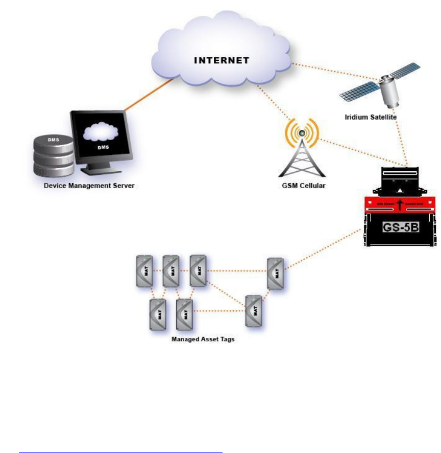
It is also capable of acting as a node and/or as a Gateway in CGTS’s MiST™ Mesh Network, thus
allowing lowest-cost reporting and enabling the formation of Mesh networks anywhere,
anytime.
Figure 1: GS-5B Reporting Path, Acting as a Gateway for a Mesh Network
3.1 GS-5B
The Global Sentinel 5 – Beam Mount (GS-5B) is a container tracking device with a number of
sensors to confirm the integrity of the shipment, a GPS radio to tracking the location of the
container it is on, a cellular radio for low-cost reporting in urban areas, a satellite radio for use
outside of developed areas and CGTS’s own Mesh radio to either report through a Mesh
network for lowest-cost reporting or to act as a Gateway to the internet for a Mesh network.
See The Global Sentinal 5 – Beam Mount (GS-5B) for more information.
Cubic Global Tracking Solutions Page 6 of 12
451111v4d Copyright © 2011 CGTS
3.2 The Device Management Center
The Device Management Center (DMC), sometimes called the Device Management Server, can
be located at a CGTS facility or at an authorized user’s site. When the GS-5B sends a report, the
data’s final destination is the DMC. With the purchase of a CGTS tracking device, the customer
will be provided log-in credentials to the DMC.
The DMC provides the following services:
Secure storage of data that is transmitted from CGTS tracking devices.
Secure system management and configuration of CGTS tracking devices.
Worldwide health monitoring of CGTS tracking devices.
Routine and Unscheduled/Unplanned Event notifications to authorized individuals via
email or short messaging service (SMS).
Software upgrade of deployed devices (future functionality).
3.3 Managed Asset Tags
The Managed Asset Tags (MATs) are small asset tracking devices capable of forming and joining
with other MATs to form CGTS MiST™ Mesh Network through a fixed or mobile Gateway to the
DMC. MATs have a number of sensors to monitor its or its asset’s condition, as well as humidity,
light, etc. It may also have a GPS receiver to track its location.
3.4 CGTS MiST™ Mesh Network
CGTS MiST™ Mesh Network is an ad-hoc, self-forming, self-healing Mesh network formed by
MATs and Gateway devices. MATs and other node devices report status and location data to the
DMC through Gateways devices.
The CGTS MiST™ Mesh Network allows for multiple paths between the MATs and the Gateways
in the network. This allows the CGTS MiST™ Mesh Network to “heal” itself if a node or number
of nodes drop off of the network.
Cubic Global Tracking Solutions Page 7 of 12
451111v4d Copyright © 2011 CGTS
4 The Global Sentinel 5 – Beam Mount (GS-5B)
The GS-5B (below) is an autonomous device that can track the location of a shipping container,
monitor the integrity of the cargo, report the status and location of itself from anywhere in the
world, and act as a Gateway for a CGTS MiST™ Mesh Network. The GS-5B is based on GS-5x
hardware platform.
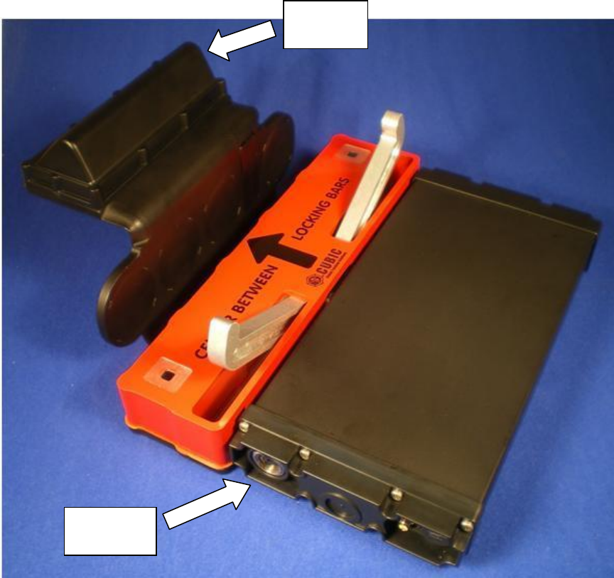
Figure 2: Global Sentinel 5 – Beam Mount
As its name suggests, the GS-5B is intended to be mounted on the ceiling beam of a shipping
container’s door frame. When mounted, only the radome is visible from the outside of the
shipping container and all of the electronics and sensors are inside the container. Refer to the
GS-5B Installation Manual for more information.
Antenna
Radome
Interface
Endcap
Cubic Global Tracking Solutions Page 8 of 12
451111v4d Copyright © 2011 CGTS
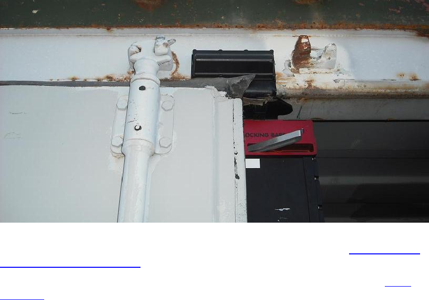
Figure 3: GS-5B as mounted
Within the Antenna Radome are the antennas for the GS-5B’s GPS receiver, Mesh radio, GSM
radio and Satellite radio. Antenna patterns for these antennas can be found in Appendix A: GS-
5B Integrated Antenna Patterns.
The Interface Endcap contains all of the user interfaces and external connectivity. See GS-5B
Interfaces for more details. Also, a covert Mesh antenna is hidden within it. The purpose of this
antenna is to extend Mesh network coverage to the inside of the shipping container on which
the GS-5B is mounted, while the Mesh antenna in the radome provides coverage to MAT tags
outside of the shipping container.
The GS-5B’s standard operating mode is to periodically report its status and location to the
DMC. The reporting interval is adjustable both via user settings and through the use of
geographically defined “GeoZones”. It can also send “alerts” when unplanned deviations from
route or unauthorized activities, such as an unauthorized door opening, occurs. Alert conditions
are user-settable through the DMC. Refer to the GS-5B Installation Manual for more details.
On a CGTS MiST™ Mesh Network, the GS-5B has two operating modes:
In Sink mode, the GS-5B provides a connection between the CGTS Device Management
Center (DMC) and the MATs in the CGTS Mesh network. In this usage mode, the GS-5B
can be referred to as a “Mobile Mesh Gateway” or MMG. MATs communicate to the
MMG using CGTS’s proprietary mesh technology. The MMG communicates with the
DMC through the Internet via Iridium satellite or GSM cellular connection. The GS-5B
acts like a MMG when it is the only or the most efficient path to the Internet.
In Pass-Through mode, the GS-5B behaves as another node on the CGTS MiST™ Mesh
Network. It will accept connections from other nodes and forward data to a Gateway
but does not communicate with the DMC directly. The GS-5B acts like this when there is
a lower-cost Gateway than itself nearby.
Refer to the CGTS Mesh Network User’s Guide for more information on Mesh usage modes.
Cubic Global Tracking Solutions Page 9 of 12
451111v4d Copyright © 2011 CGTS
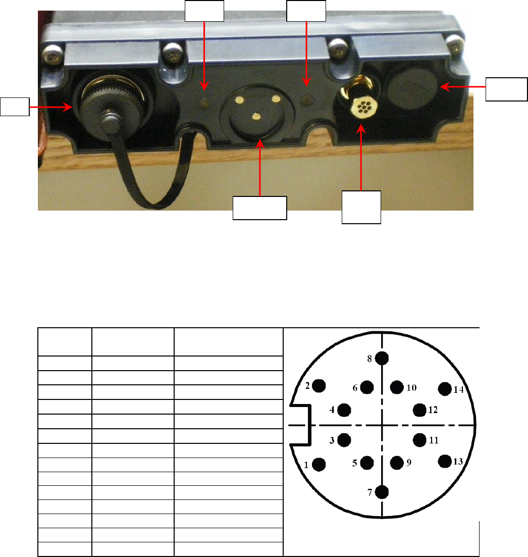
4.1 GS-5B Interfaces
Figure 4: GS-5B Interface connector
J1: The J1 Connector allows the GS-5B to communicate and source power to external
peripherals and sensors. It also allows the user to supply power to the GS-5B and to issue
console commands to it. While the connector is sealed to IP-67 compliance when unmated,
users should put the cover on J1 when not in use to keep its contacts free of dust, moisture and
other contaminants.
Table 1: J1 Pin-out
Pin
Number
Signal Name
Signal Direction (with
respect to the GS-5B)
Pin-out when viewing the face of J1
1
External Power
Input
2
Power Ground
3
Sensor Power
Output
4
Sensor Signal
Input
5
Ground
6
Console TxD
Input
7
Console RxD
Output
8
Ground
9
RESERVED
RESERVED
10
RESERVED
RESERVED
11
Ground
12
Ext. Serial TxD
Input
13
Ext. Serial RxD
Output
14
Loopback
Input
The console and serial signals comply with EIA-232 standard voltage levels by default. By
request, CGTS can customize either serial interface to operate on TTL I/O levels.
T/rH
Port
iButton
LED
Vent
J1
ALS

Cubic Global Tracking Solutions Page 10 of 12
451111v4d Copyright © 2011 CGTS
T/rH Port: Keep this port free of blockage and grime. Otherwise the GS-5B will not be able to
report accurate temperature and humidity readings of the inside of the shipping container on
which it is mounted.
iButton Socket: The primary control and arming method of the GS-5B. See iButtons for more
information on iButtons.
Status LED: A Bi-color LED gives a basic indication of the GS-5B’s operational (Arming/On/Off)
status.
Ambient Light Sensor (ALS): This ALS is used in conjunction with other GS-5B sensors to
detect whether an unauthorized intrusion has occurred. The sensitivity of the ALS ranges from
<TBD>. See Appendix B: Sensor Characteristics for more details.
Vent: This Gore-Tex vent allows the GS-5B to equalize its internal air pressure to the air
pressure of its environment without allowing moisture into the GS-5B. THE GORE-TEX VENT IS
NOT A CAP OR CONNECTOR. DO NOT ATTEMPT TO REMOVE.
Covert Mesh antenna: Behind the interface endcap is a Mesh antenna. It is intended to allow
MAT tags inside a shipping container to communicate to a Mesh network outside of the
container even when the doors are closed. The radiation pattern for this antenna can be found
in Appendix A: GS-5B Integrated Antenna Patterns
4.2 Sensor Box
The Sensor Box of the GS-5B is made to monitor the doors of the shipping container and detect
if a door has been opened or removed. See Appendix B: Sensor Characteristics for full sensor
characteristics.
4.2.1 Arms
The two arms are the GS-5B’s primary method of detecting if a door has been opened. The
sensor uses an adjustable algorithm at the start of each trip to determine what constitutes a
door opening or closure. This algorithm is automatic, and requires no interaction from the
installer. It is also self-adjusting, allowing the same GS-5B to be used on drastically different
containers with equal effectiveness.
These arms can detect objects that are perfectly flat against the sensor box and objects that are
up to 2” away from the face of the container.
4.2.2 Proximity Sensors
In addition to the arms, a pair of non-contacting proximity sensors is also in place to detect if the
doors have been opened, and to determine if a malicious party is attempting to fool the sensors.
These proximity sensors can detect objects that are as far as 6” away from the face of the sensor
box as well as objects flat against the sensor box.
4.2.3 Ambient Light Sensors
The sensor box contains ambient light sensors (ALS) to detect unauthorized intrusion into the
shipping container.
The sensitivity of the ALS of the sensor box ranges from 0.0075 lux to 150 lux.

Cubic Global Tracking Solutions Page 11 of 12
451111v4d Copyright © 2011 CGTS
4.3 Hookplate Demount Sensor
Hidden in the hookplate is a sensor that determines whether the GS-5B is mounted on the beam
of a shipping container. It is located within the radome.
4.4 iButtons
The CGTS iButtons offer an authenticated user interface to control a GS-5B. Each GS-5B comes
with a set of iButtons containing a:
Yellow = ON iButton: turns on (disarms) the GS-5B.
Black = OFF iButton: turns off the GS-5B.
Red = REPORT iButton: forces the GS-5B to send a report.
Figure 5: CGTS iButtons
4.5 Installing, Configuring and Maintaining a GS-5B
Refer to the GS-5B Installation Manual.
Cubic Global Tracking Solutions Page 12 of 12
451111v4d Copyright © 2011 CGTS
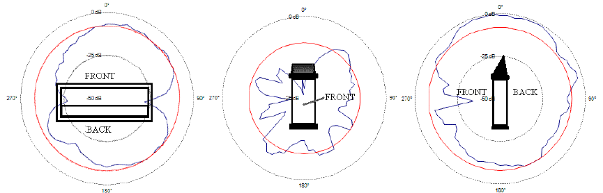
Appendix A: GS-5B Integrated Antenna Patterns
Figure 6: GS-5B ISM antenna pattern, normalized to Max signal from all orientations
Azimuth Plane
Theta=0
Elevation Plane
Phi=0
Elevation Plane
Phi=90
<TODO other patterns>
Appendix B: Sensor Characteristics
<TODO>