Cubic Transportation Systems ACT07 Access Control Card Reader User Manual manual
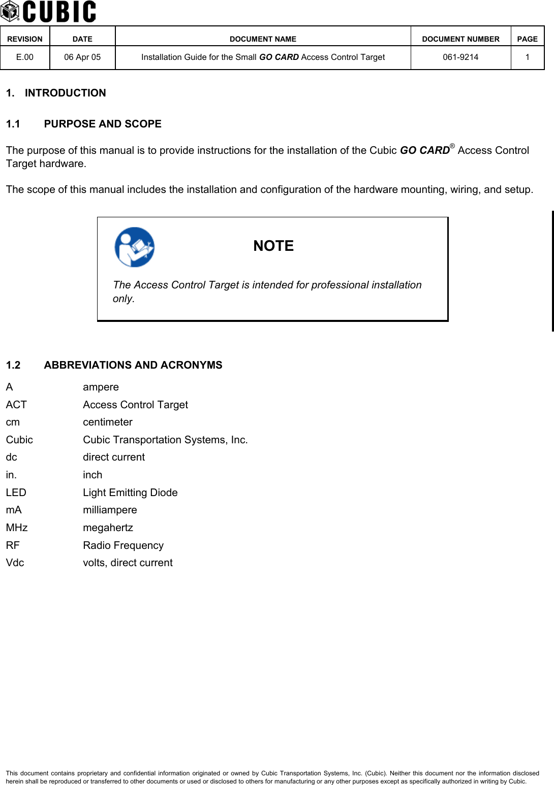
Cubic Transportation Systems, Inc. Access Control Card Reader manual
UserManual.wiki
>
Cubic Transportation Systems
>
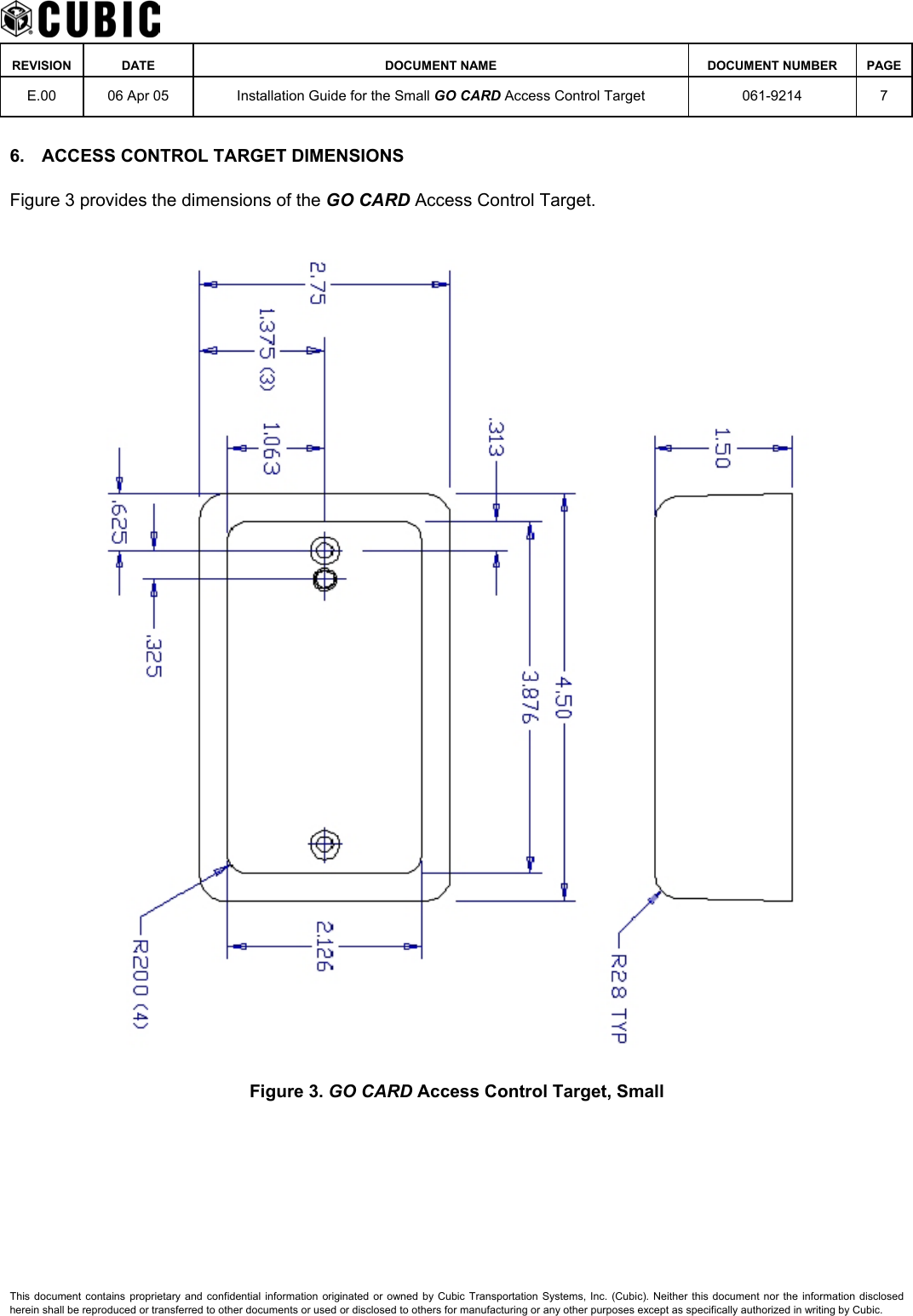
ACT07 User Manual
manual
Navigation menu
Upload a User Manual
Namespaces
Wiki Guide
HTML
PDF
Info
Views
User Manual
Discussion / Help
Navigation