Cubic Transportation Systems RTD01 TRI-Reader 2 User Manual 4200 46001 B 00
Cubic Transportation Systems, Inc. TRI-Reader 2 4200 46001 B 00
Contents
- 1. manual
- 2. addendum
manual

USER MANUAL
for the
Cubic Transportation Systems, Inc.
Tri-Reader 2
Cubic Document No. 4200-46001
Revision B.00
September 25, 2003

September 25, 2003 4200-46001 , Rev. B.00
ii User Manual for the Cubic Tri-Reader 2
This page intentionally blank

4200-46001, Rev. B.00 September 25, 2003
User Manual for the Cubic Tri-Reader 2 iii
Proprietary Notice
The information disclosed herein contains proprietary rights of Cubic Transportation Systems,
Inc. Neither this document nor the information disclosed herein shall be reproduced or
transferred to other documents. Nor shall the information be used or disclosed to others for
manufacturing or any other purposes except as specifically authorized in writing by Cubic
Transportation Systems, Inc.

September 25, 2003 4200-46001 , Rev. B.00
iv User Manual for the Cubic Tri-Reader 2
This page intentionally blank

4200-46001, Rev. B.00 September 25, 2003
User Manual for the Cubic Tri-Reader 2 v
Document Control List
Revision Date Description
A.00 May 28, 2003 Initial release.
B.00 September 25, 2003 1) Changed “MiniRTD” to “Tri-Reader 2” throughout.
2) Updated paragraph 1.7.1.
______________________________________________ ________________
Author—Approved for release Date
Thomas Busch-Sorensen
______________________________________________ ________________
Engineering Services Manager—Approved for release Date
Augie Cammarota
______________________________________________ ________________
Program Manager—Approved for release Date
Russell Shon
______________________________________________ ________________
Technical Editor—Approved for release Date
Mike Smith
______________________________________________ ________________
Configuration Management—Approved for release Date

September 25, 2003 4200-46001 , Rev. B.00
vi User Manual for the Cubic Tri-Reader 2
This page intentionally blank

4200-46001, Rev. B.00 September 25, 2003
User Manual for the Cubic Tri-Reader 2 vii
Table of Contents
Title Page
Proprietary Notice............................................................................................................................ iii
Document Control List.....................................................................................................................v
List of Figures................................................................................................................................. vii
List of Tables.................................................................................................................................. vii
Trademarks....................................................................................................................................viii
Chapter No. Title Page
CHAPTER 1 Cubic Tri-Reader 2...................................................................................... 1-1
1.1 Introduction .................................................................................................................... 1-1
1.2 Tri-Reader 2 Antenna Type ........................................................................................... 1-2
1.3 Tri-Reader 2 Interface to Host Unit................................................................................ 1-2
1.4 RF Communication ....................................................................................................... 1-2
1.4.1 RF Field Strength........................................................................................... 1-3
1.4.2 Modulation Types ........................................................................................... 1-3
1.5 Tri-Reader 2 Printed Circuit Board Size........................................................................ 1-3
1.6 Tri-Reader 2 Physical Interfaces................................................................................... 1-4
1.7 Notices........................................................................................................................... 1-6
1.7.1 Federal Communications Commission Notices............................................ 1-6
1.7.2 Industry Canada Notices................................................................................ 1-6
List of Figures
Title Page
Figure 1. Tri-Reader 2 Antenna.................................................................................................... 1-2
List of Tables
Title Page
Table 1. J5 Pinouts....................................................................................................................... 1-5

September 25, 2003 4200-46001 , Rev. B.00
viii User Manual for the Cubic Tri-Reader 2
Trademarks
Cubic® is a registered trademark of Cubic Corporation.
GO CARD® is a registered trademark of Cubic Transportation Systems, Inc.
Tri-Reader® is a registered trademark of Cubic Transportation Systems, Inc.

4200-46001, Rev. B.00 September 25, 2003
User Manual for the Cubic Tri-Reader 2 1-1
CHAPTER 1 Cubic Tri-Reader 2
1.1 Introduction
The Cubic Transportation Systems, Inc. (Cubic) Tri-Reader® 2 will serve as a front
end for a remote ticketing device used for automatic fare collection (AFC) in public
transportation systems (e.g., bus, rail, subway, etc.). It can be used in ticket
validators, ticket vending machines, gates, and other AFC equipment. This
equipment can be onboard vehicles or in fixed ground locations. The Tri-Reader 2
will be responsible for direct communication with a Contactless Smart Card (CSC),
which is a type of radio frequency (RF) tag. The design caters for at least three
types of CSC, namely Type A, Type B, and GO CARD®.
Interpretation of the information stored on the CSC, as well as the processing of the
revenue collection transaction, will be done by the Tri-Reader 2 itself, based on
faretables and hot-lists provided by the host computer.
The firmware on the Tri-Reader 2 is designed to be updated in-system using
FLASH-based technology. It will therefore be possible to cater, within limits, for
different CSC types and configurations — if so required for the future.
In broad terms, the communication task will therefore proceed as follows:
1. The Tri-Reader 2 will power the CSC through radiation by an induced RF
field.
2. By sequencing through the communication protocols for the different
cards, it will detect the card type by checking for the associated
response.
3. Once the card type and therefore its communication mechanism is
known, the Tri-Reader 2 will read and write data on the card according to
the fare rules in the faretables.
4. The Tri-Reader 2 will pass data to and from the CSC by using the
appropriate protocol for modulation and demodulation of the signal.
September 25, 2003 4200-46001, Rev. B.00
1-2 User Manual for the Cubic Tri-Reader 2
1.2 Tri-Reader 2 Antenna Type
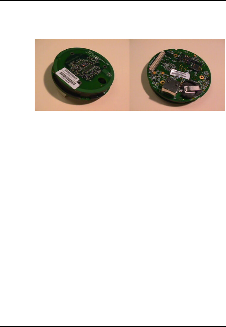
The Tri-Reader 2 is a loop antenna with a diameter of 78 mm.
Figure 1. Tri-Reader 2 Antenna
1.3 Tri-Reader 2 Interface to Host Unit
There will be a one-to-one (RS422) link between the Tri-Reader 2 and the Host unit.
The Tri-Reader 2 will operate as a single Remote Ticketing Device (RTD).
A shielded RJ45 connector connects the Tri-Reader 2 to the Host unit. This link is
for the serial data.
1.4 RF Communication
All RF communication between the Tri-Reader 2 and the CSC will be accomplished
at a carrier frequency of 13.56 MHz according to modulation/demodulation
schemes for ISO 14443 Type A, ISO 14443 Type B, and/or GO CARD
requirements. At a minimum, the RF field will be able to power three CSCs in close
proximity. The transmitter antenna is tuned to its resonance during production. The
modulation/ demodulation scheme will also be automatically selected by the local
controller.

4200-46001, Rev. B.00 September 25, 2003
User Manual for the Cubic Tri-Reader 2 1-3
1.4.1 RF Field Strength
The magnetic field strength is approximately 8 A/m in the center of the antenna and
falls off by the third power of the distance. The electric field strength is determined
by the voltage applied to the coil as well as the efficiency of the antenna as a
radiator. The effective applied voltage is approximately 6 Vrms, but the antenna is
fitted with a balanced shield, reducing the apparent common mode voltage to 0.
1.4.2 Modulation Types
The signals for communication between the Tri-Reader 2 and the CSC will differ
between card types. In some cases, data will be modulated onto a carrier only,
while in others a subcarrier will also be present. The modulation schemes used for
communication also differ from one card type to another as described below.
CSC Type A: Reader-to-card, ASK 100% modified miller, 106 kbit/s. Card-
to-reader, ASK - Manchester, load modulation - subcarrier
fc/16, 847.5 kHz, 106 kbit/s.
CSC Type B: Reader-to-card, ASK 10% modulation index NRZ, 106 kbit/s.
Card-to-reader, BPSK-NRZ load modulation subcarrier fc/16,
847.5 kHz, 106 kbit/s.
Type GO CARD: Reader-to-card, ASK 8% modulation index NRZ, 115.2 kbit/s.
Card-to-reader, ASK-NRZ load modulation, 115.2 kbit/s.
1.5 Tri-Reader 2 Printed Circuit Board Size
The Tri-Reader 2 consists of an 86.5 mm diameter circular digital board and an 83
mm diameter antenna board. Thickness, including components and antenna board,
is 17 mm, except for the RJ45 connector which extends 10 mm above the
components on the back of the board, giving a maximum thickness of 27 mm.

September 25, 2003 4200-46001, Rev. B.00
1-4 User Manual for the Cubic Tri-Reader 2
1.6 Tri-Reader 2 Physical Interfaces
The following physical interfaces apply to the Tri-Reader 2:
1. The Tri-Reader 2 is powered from 5 to 28 Vdc. It can draw a maximum
current of 1.5A (at startup) and dissipates up to 2 Watts. This can be
supplied either via an expansion connector (J8) or it can be tapped from
the host communication cable, in which case it will come in on the RJ45
serial comms connector (see the pinouts below).
2. The Tri-Reader 2 comms can be set to be either RS232 or RS422/485
levels. RS232 mode is selected by software.
3. The Tri-Reader 2 automatic baud rate detection between 9,600 bps and
921,600 bps.
4. If RS232 is used, only two of the four comms lines on the RJ45 connector
are required. Pin 2 on the RJ45 connector is the Tri-Reader 2 receive line
(232Rx) and should be connected to the host computer Tx output (pin 3
on a normal DB9). Pin 6 on the RJ45 connector is the Tri-Reader 2
transmit (232Tx) line and should be connected to the host computer Rx
input (pin 2 on a normal DB9).
5. If RS422 or RS485 is used, 485RxL must be taken to the host transmit
low, 485RxH must be taken to the host transmit high, 485TxL must be
taken to the host receive low, and 485TxH must be taken to the host
receive high.
6. The Tri-Reader 2 has an onboard tri-color LED indicator.
7. The RJ45 communications connector is a shielded type that is mounted
in the J5 position. It mates to any standard RJ45 cable connector. Table 1
provides the J5 pinouts.
4200-46001, Rev. B.00 September 25, 2003
User Manual for the Cubic Tri-Reader 2 1-5
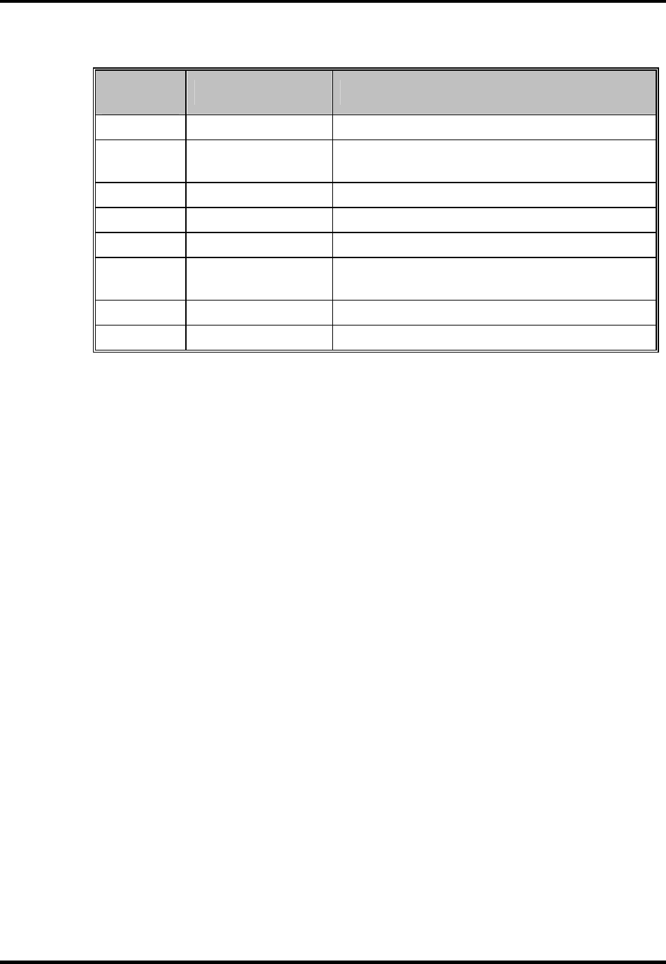
Table 1. J5 Pinouts
Pin
Number Name Description
1 485RxH Tri-Reader 2 RS422/RS485 Receive high.
2 232Rx_485RxL Tri-Reader 2 RS232 Receive or
RS422/RS485 Receive low.
3 485TxH Tri-Reader 2 RS422/RS485 Transmit high.
4 5_TO_28V Power Supply Input (5 to 28 Vdc).
5 GND Power Supply Ground.
6 232Tx_485TxL Tri-Reader 2 RS232 Transmit or
RS422/RS485 Transmit low.
7 5_TO_28V Power Supply Input (5 to 28 Vdc).
8 GND Power Supply Ground.

September 25, 2003 4200-46001, Rev. B.00
1-6 User Manual for the Cubic Tri-Reader 2
1.7 Notices
1.7.1 Federal Communications Commission Notices
The following Federal Communications Commission (FCC) notices apply:
1. The user is cautioned that changes or modifications to the Tri-Reader 2
that are not expressly approved by Cubic could void the user's authority to
operate this equipment.
2. “NOTE: This equipment has been tested and found to comply with the
limits for a Class B digital device, pursuant to Part 15 of the FCC Rules.
These limits are designed to provide reasonable protection against
harmful interference in a residential installation. This equipment
generates, uses, and can radiate radio frequency energy and, if not
installed and used in accordance with the instructions, may cause
harmful interference to radio communications. However, there is no
guarantee that interference will not occur in a particular installation. If this
equipment does cause harmful interference to radio or television
reception, which can be determined by turning the equipment off and on,
the user is encouraged to try to correct the interference by one or more of
the following measures:
Reorient or relocate the receiving antenna.
Increase the separation between the equipment and the receiver.
Connect the equipment into an outlet on a circuit different from that
to which the receiver is connected.
Consult the dealer or an experienced radio/TV technician for help.”
1.7.2 Industry Canada Notices
The following Industry Canada notices apply:
This Class B digital apparatus complies with Canadian ICES-003.
Cet appareil numérique de la classe B est conforme à la norme NMB-003 du
Canada.
Operation is subject to the following two conditions: (1) this device may not cause
interference, and (2) this device must accept any interference, including
interference that may cause undesired operation of the device."