Current Technologies 6030A CURRENT Gateway-Bridge OH 6030 User Manual Install Guide
Current Technologies, LLC CURRENT Gateway-Bridge OH 6030 Install Guide
UserManual.wiki
>
Current Technologies
>
6030A User Manual
>
Install Guide
Contents
1.
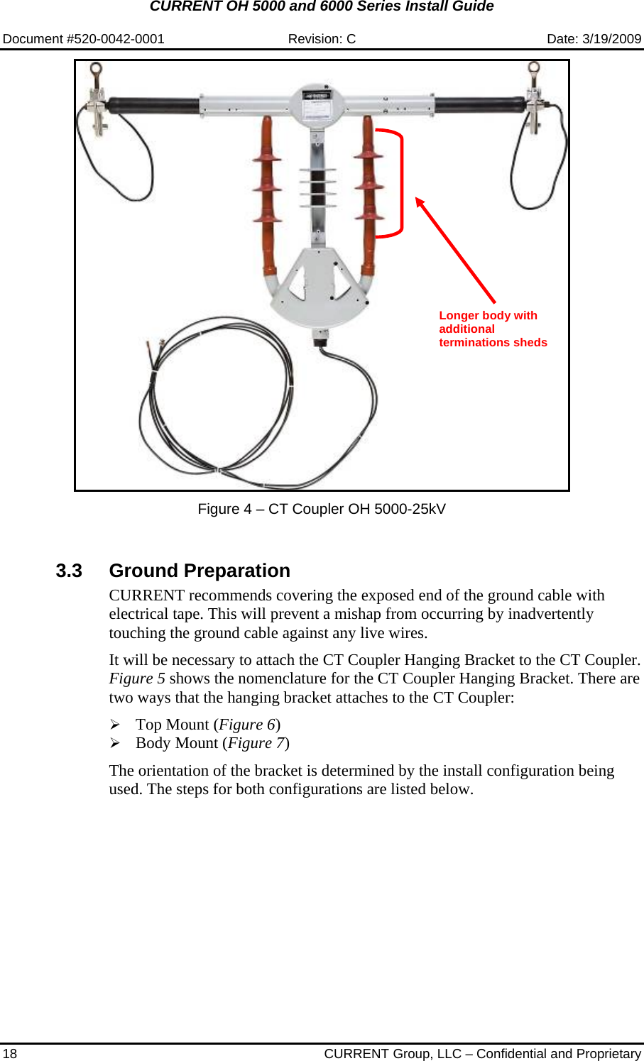
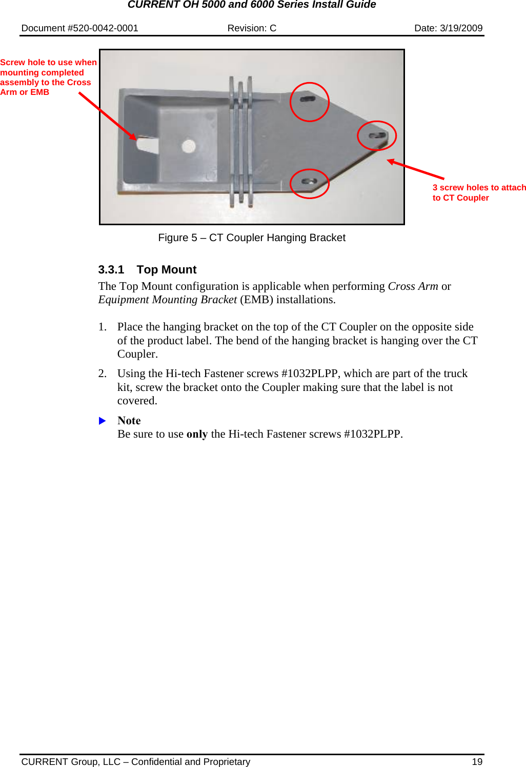
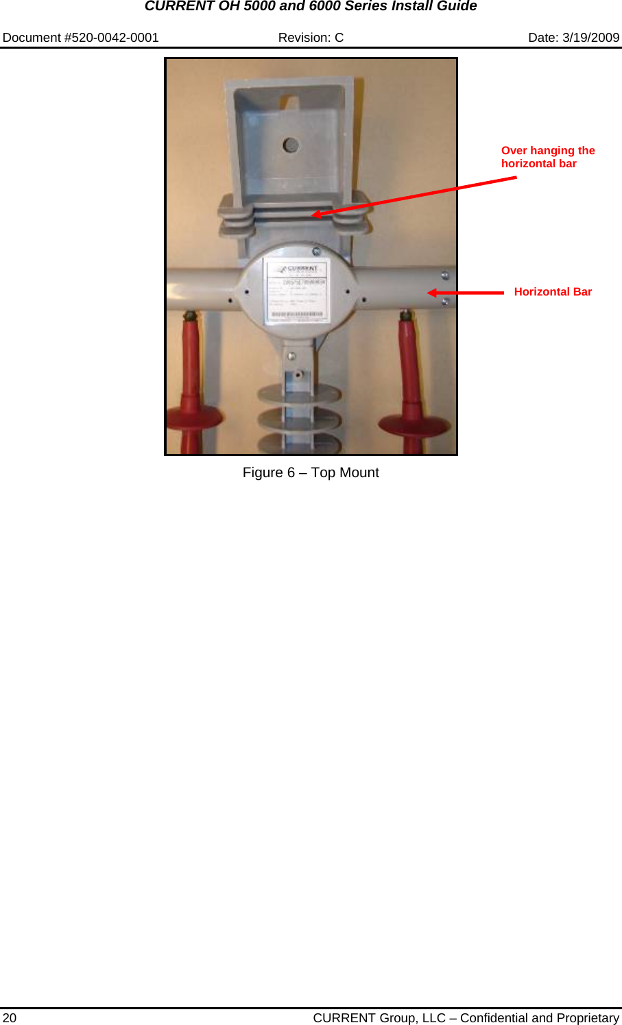
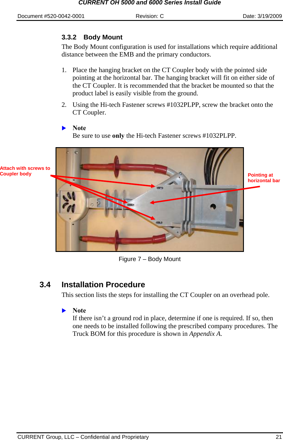
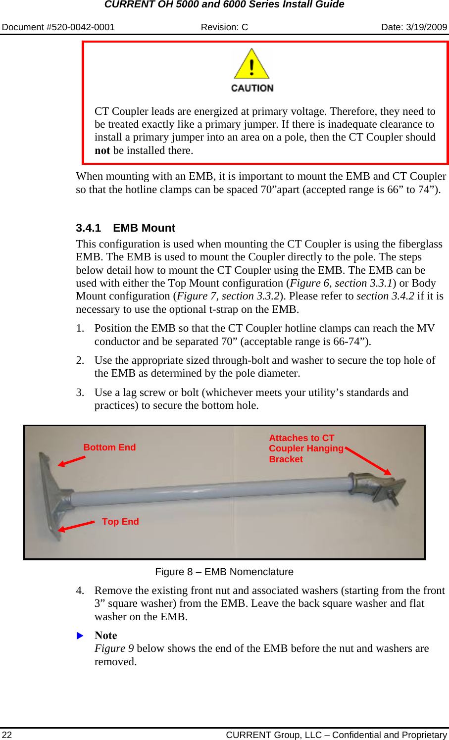
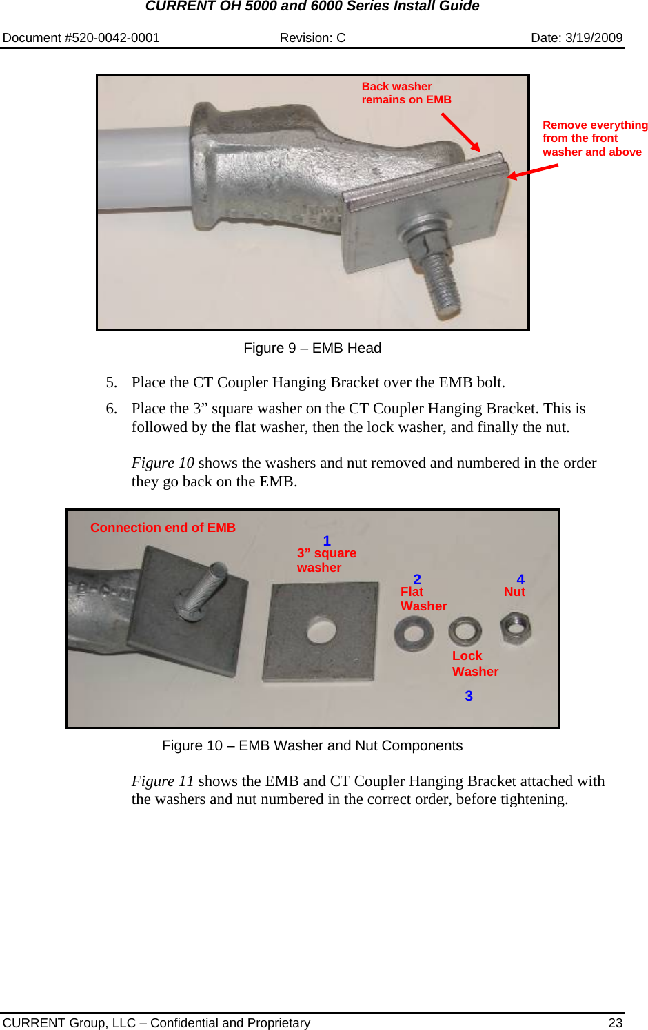
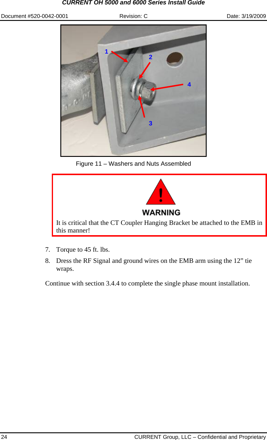
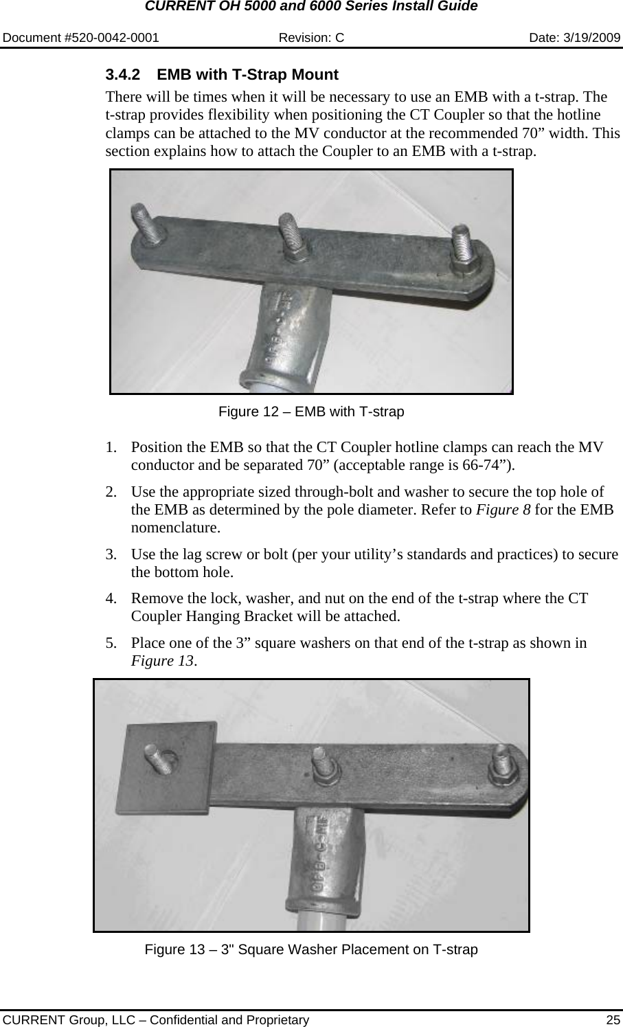
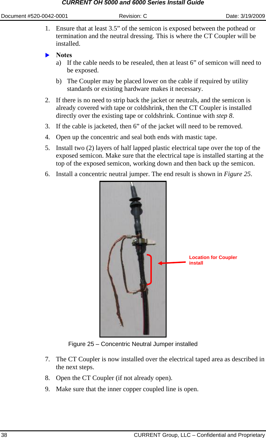
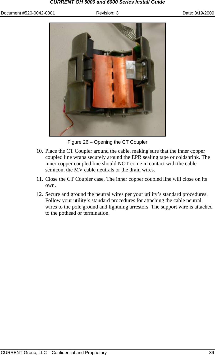
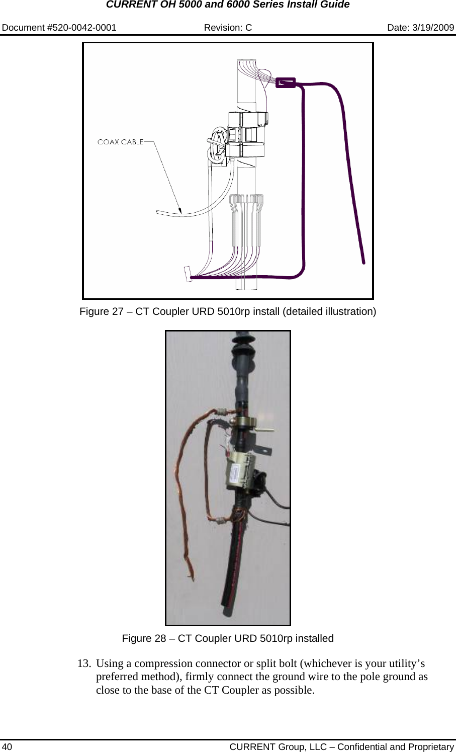
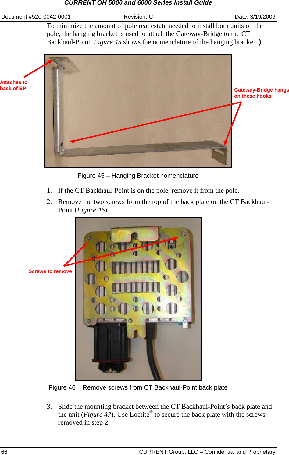
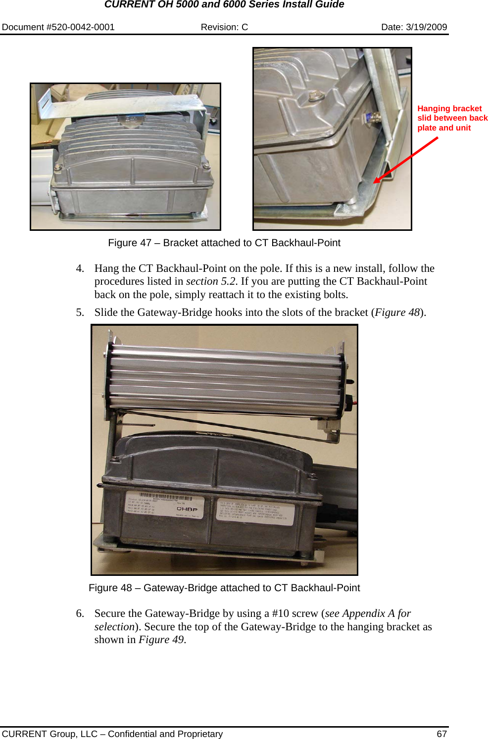
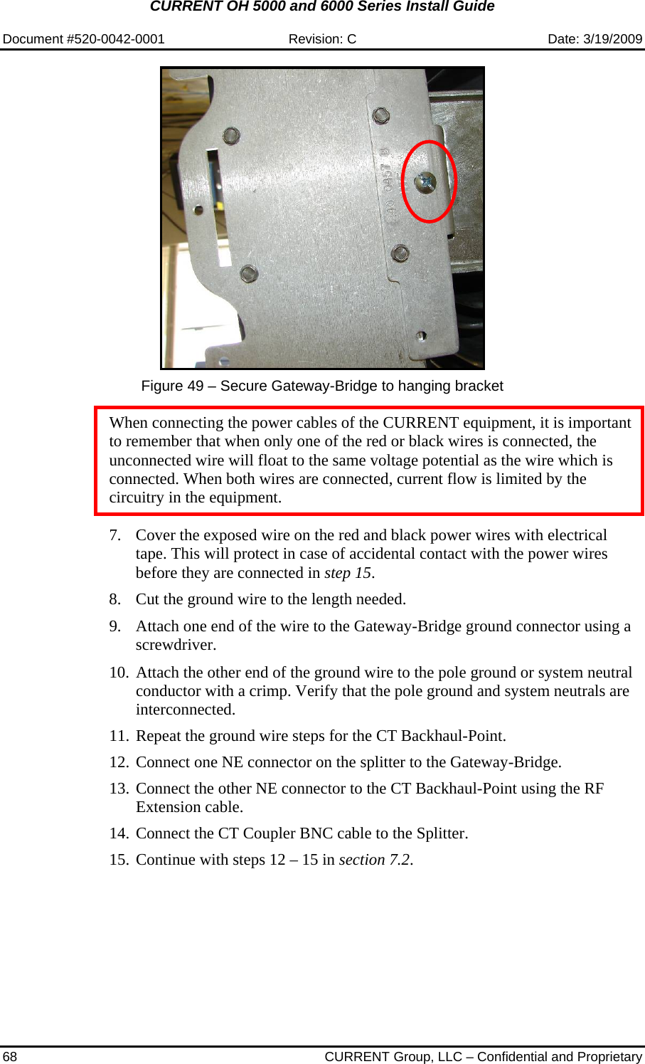
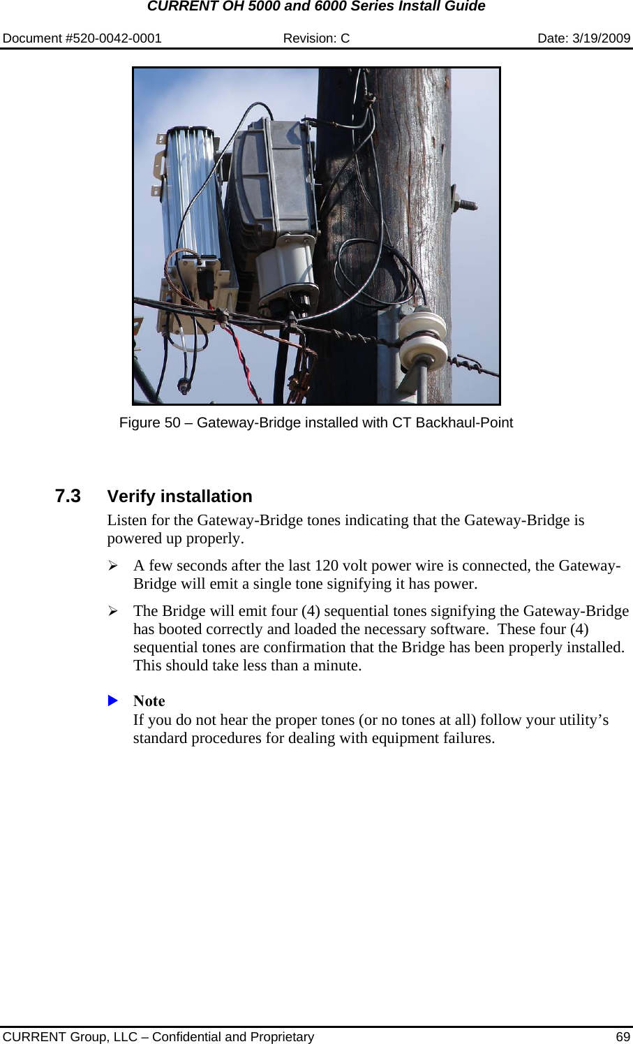
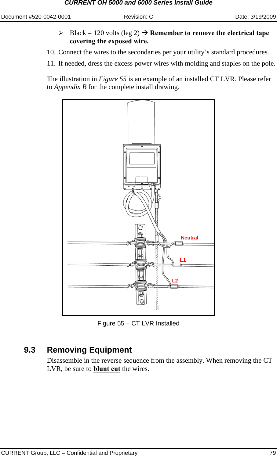
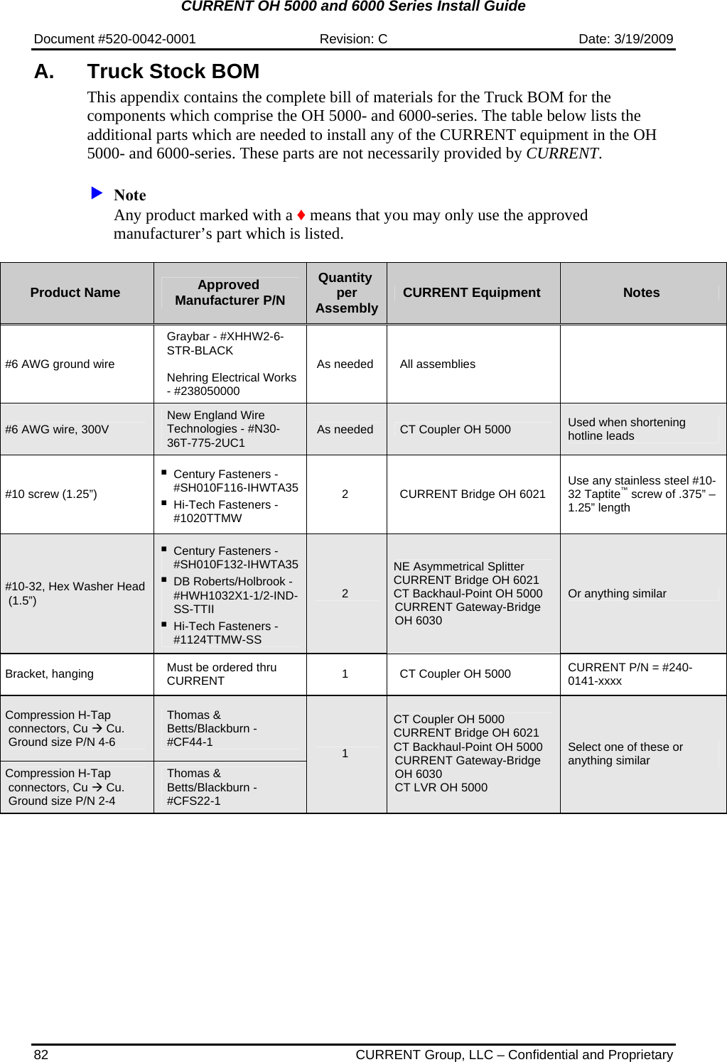
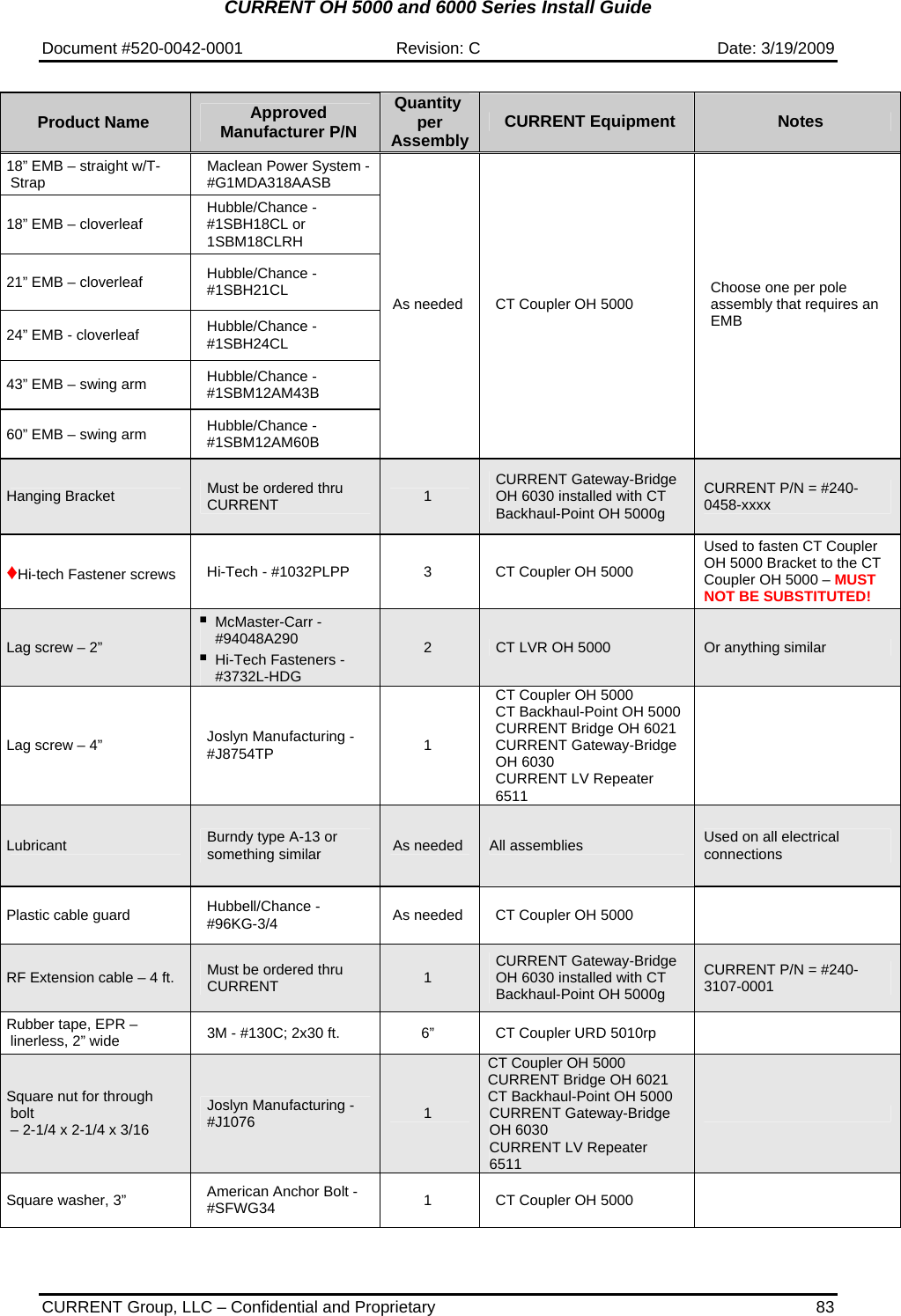
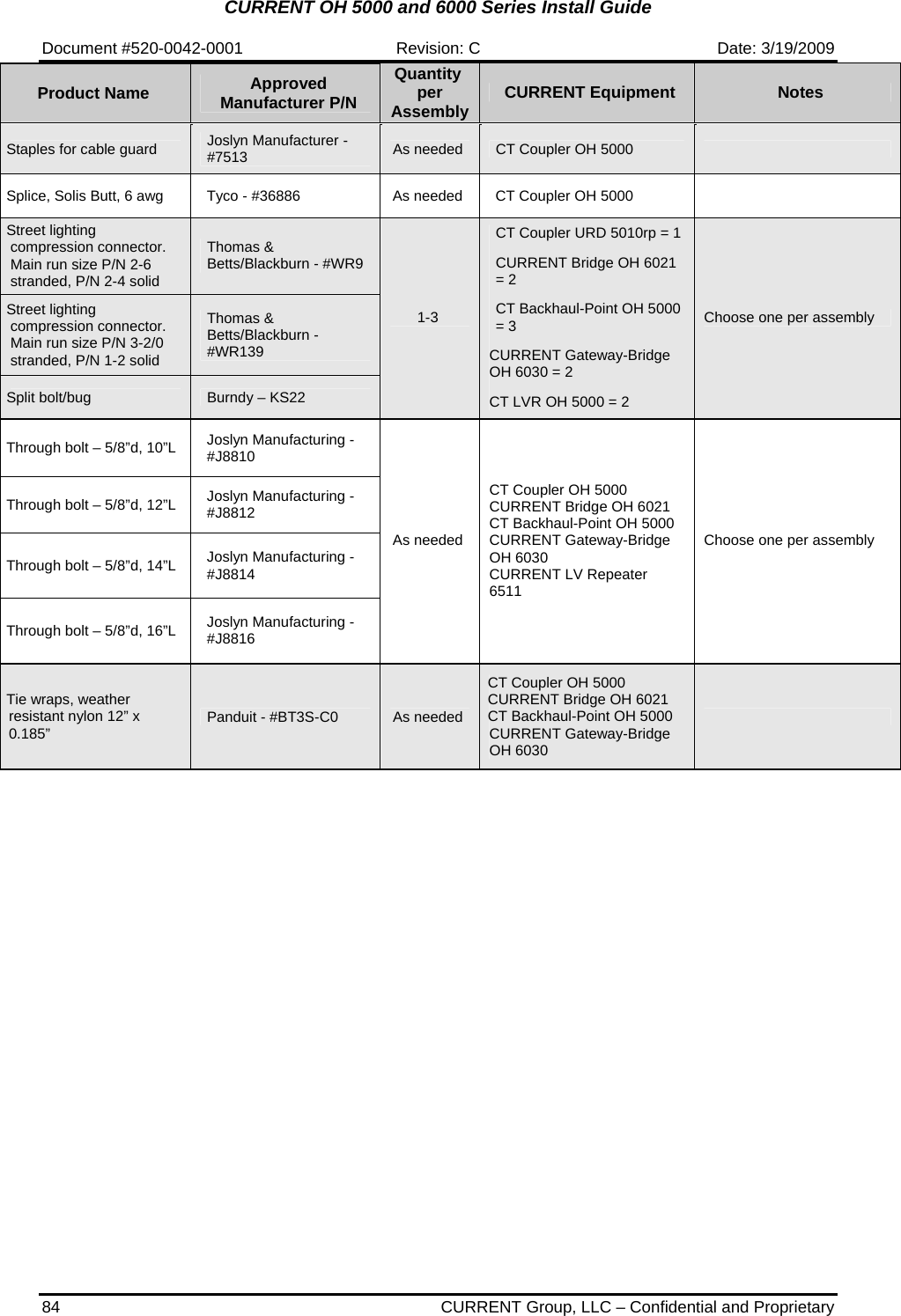
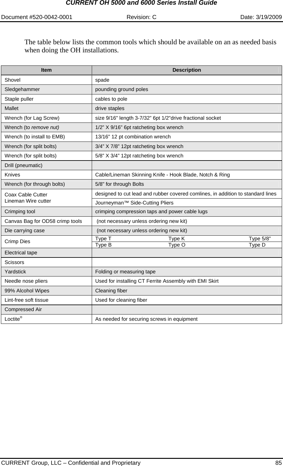
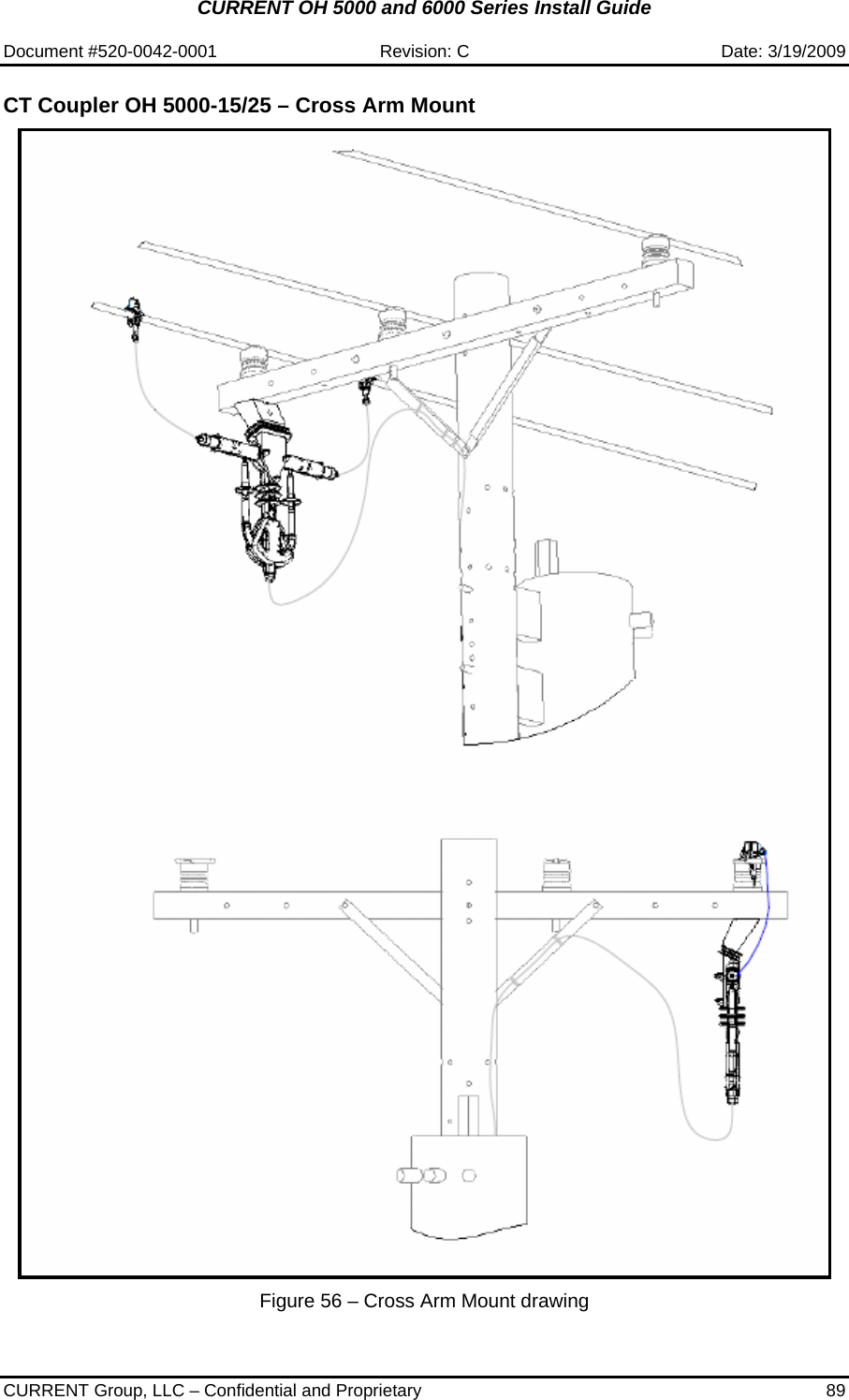
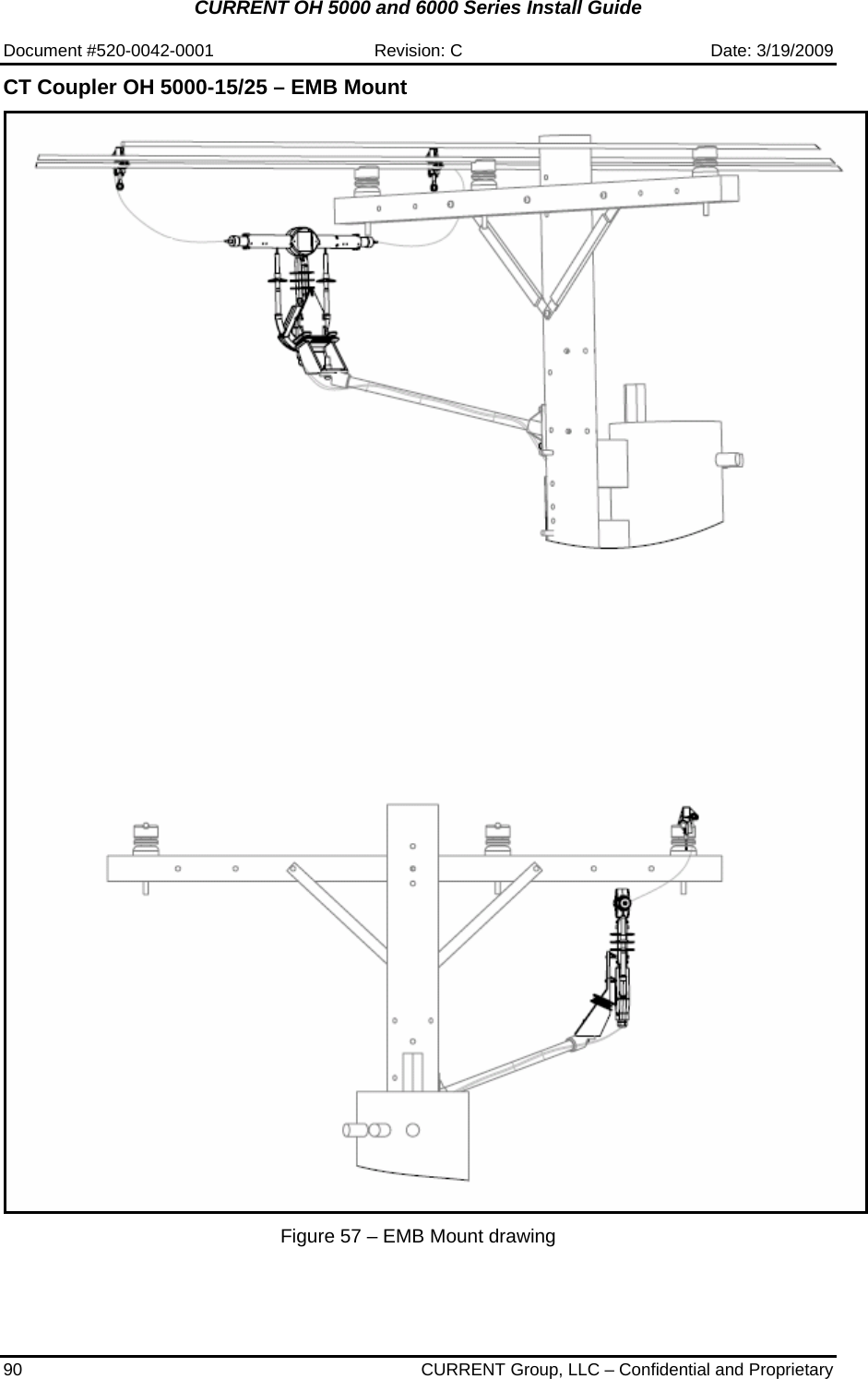
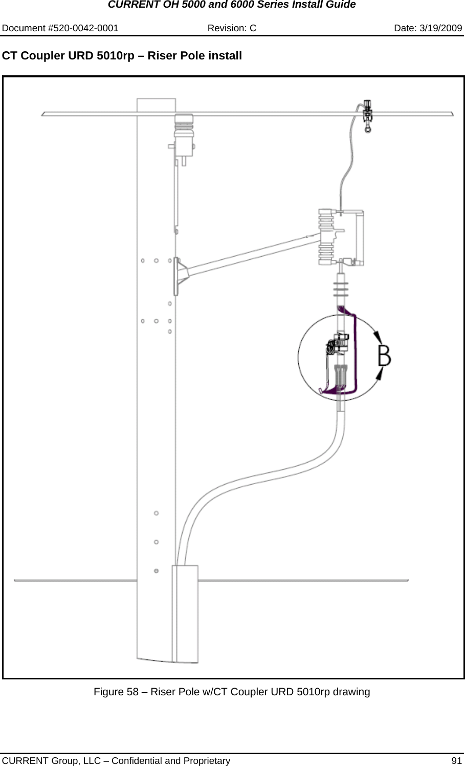
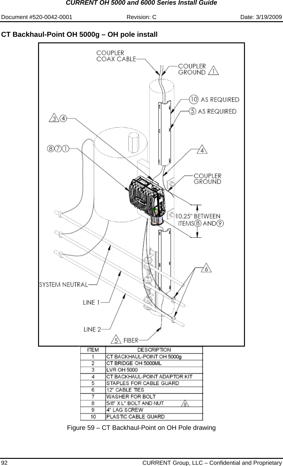
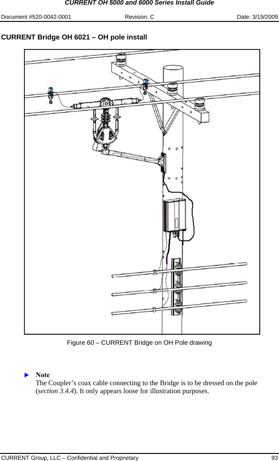
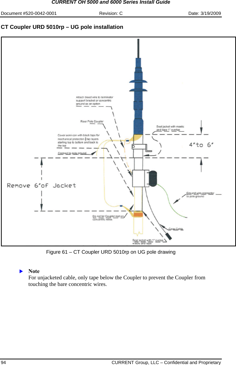
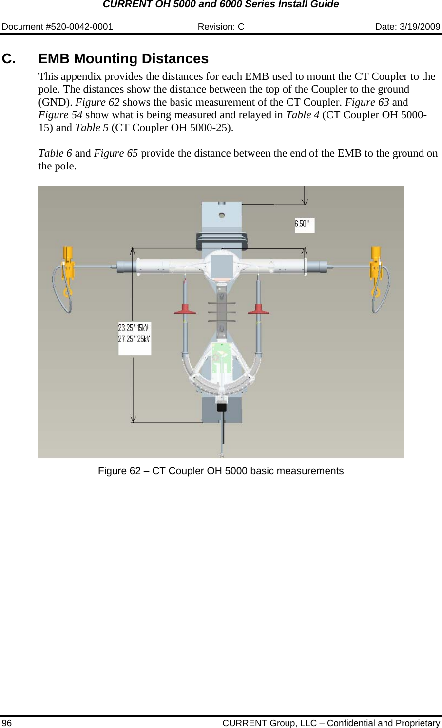
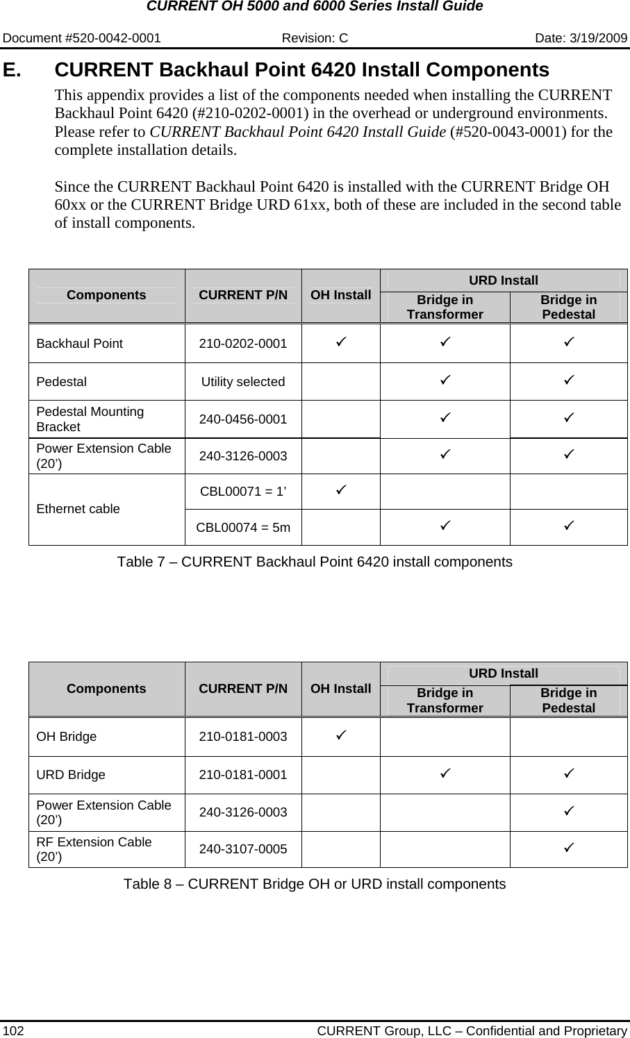
Install Guide
2.
Notching Instructions
Install Guide
Navigation menu
Upload a User Manual
Namespaces
Wiki Guide
HTML
PDF
Info
Views
User Manual
Discussion / Help
Navigation