CyberTAN Technology RV315W Cisco Broadband Wireless VPN Router User Manual RV315W AG
CyberTAN Technology Inc. Cisco Broadband Wireless VPN Router RV315W AG
User Manual.pdf
Cisco Small Business
RV315W Broadband Wireless VPN Router
ADMINISTRATION
GUIDE

© 2013 Cisco Systems, Inc. All rights reserved. OL-25648-01
Cisco and the Cisco logo are trademarks or registered trademarks of Cisco and/or its affiliates in the U.S. and other countries. To view a list of Cisco trademarks,
go to this URL: www.cisco.com/go/trademarks. Third-party trademarks mentioned are the property of their respective owners. The use of the word partner
does not imply a partnership relationship between Cisco and any other company. (1110R)

© 2013 Cisco Systems, Inc. All rights reserved. OL-25648-01
Federal Communication Commission Interference Statement
This device complies with Part 15 of the FCC Rules. Operation is subject to the
following two conditions: (1) This device may not cause harmful interference, and
(2) this device must accept any interference received, including interference that
may cause undesired operation.
This equipment has been tested and found to comply with the limits for a Class B
digital device, pursuant to Part 15 of the FCC Rules. These limits are designed to
provide reasonable protection against harmful interference in a residential
installation. This equipment generates, uses and can radiate radio frequency
energy and, if not installed and used in accordance with the instructions, may
cause harmful interference to radio communications. However, there is no
guarantee that interference will not occur in a particular installation. If this
equipment does cause harmful interference to radio or television reception, which
can be determined by turning the equipment off and on, the user is encouraged to
try to correct the interference by one of the following measures:
•Reorient or relocate the receiving antenna.
•Increase the separation between the equipment and receiver.
•Connect the equipment into an outlet on a circuit different from that to which
the receiver is connected.
•Consult the dealer or an experienced radio/TV technician for help.
FCC Caution: Any changes or modifications not expressly approved by the party
responsible for compliance could void the user's authority to operate this
equipment.
This transmitter must not be co-located or operating in conjunction with any other
antenna or transmitter.
Radiation Exposure Statement:
1. 20cm minimum when the product is operated alone without co-transmitting
with a plug-in 3G USB dongle device.
2. 33 cm minimum when the product is operated with a plug-in 3G USB device
which has maximum of 7W ERP output power.
3. For co-transmission scenario which is not covered above, please consult the RF
technician or device supplier.

Cisco RV315W Broadband Wireless VPN Router Administration Guide 1
Contents
Federal Communication Commission Interference Statement 3
Radiation Exposure Statement: 3
Chapter 1: Getting Started 5
Product Overview 5
Front Panel 5
Back Panel 8
Default Settings 9
Mounting the RV315W 10
Placement Tips 10
Wall-Mounting 10
Connecting the RV315W 11
Getting Started with the Configuration 12
Before You Begin 12
Logging in to the Configuration Utility 13
Using the Help System 13
Performing Basic Configuration Tasks 14
Changing the Default Administrator Password 14
Upgrading Your Firmware After Your First Login 14
Backing Up Your Configuration 16
Chapter 2: Using the Setup Wizard 17
Starting the Setup Wizard 17
Configuring WAN Connection 17
Configuring Default LAN Settings 21
Configuring Wireless Connection 22
Completing the Setup Wizard 27
Chapter 3: Viewing System Status 28
Device Information 28
WAN Connection 29

Cisco RV315W Broadband Wireless VPN Router Administration Guide 2
Contents
3G Wireless Connection 29
LAN Interfaces 30
WLAN Connection 30
Application Information 31
Refresh Rate 31
Chapter 4: Port Management 32
Configuring WAN Connections 32
Viewing WAN Connection Information 32
Configuring WAN Connections 33
Configuring Default Route of the Physical WAN Interface 38
Configuring Dual WAN 39
Configuring WAN1/LAN0 Interface 40
Configuring LAN 41
Configuring LAN Interfaces 41
Configuring VLAN Settings 42
Configuring Wireless Settings 43
Configuring Wireless Radio Settings 43
Configuring Wireless Security 44
Configuring 3G Wireless Connection 51
Chapter 5: Networking 53
Configuring DDNS 53
Configuring ALG 54
Configuring Port Forwarding 55
Configuring Single Port Forwarding 55
Configuring Port Range Forwarding 56
Configuring Port Triggering 57
Configuring DMZ 58
Configuring Software DMZ 58
Configuring Hardware DMZ 59

Cisco RV315W Broadband Wireless VPN Router Administration Guide 3
Contents
Configuring UPnP 59
Configuring Port Mirroring 60
Configuring Routing 60
Configuring Basic Routing Settings 61
Configuring Routing Mode 61
Configuring Inter-VLAN Routing 61
Configuring Static Routing 61
Configuring Policy-based Routing 62
Configuring Dynamic Routing 63
Viewing the Routing Table 64
Configuring IGMP 65
Chapter 6: VPN 66
Viewing IPSec VPN Status 66
Configuring IPsec VPN Policies 67
Setting Up a Site-to-Site VPN 67
Setting up a PC to Site VPN 70
Modifying or Deleting an IPsec VPN Policy 72
Chapter 7: Quality of Service (QoS) 73
Configuring Bandwidth Management 73
Configuring Flow Control Policies 74
Configuring Session Limits 75
Chapter 8: Security 77
Configuring Firewall 77
Configuring DDoS 79
Configuring Content Filtering 79
Configuring Access Control 80
Configuring Access Control Objects 80
Configuring Access Control Policies 81
Configuring MAC Address Filtering 82

Cisco RV315W Broadband Wireless VPN Router Administration Guide 4
Contents
Preventing ARP Attacks 83
Chapter 9: System Management 85
Rebooting the RV315W 85
Configuring User Accounts 86
Viewing User Information 86
Creating a New User 87
Changing User Password 87
Deleting a Local User 88
Restoring Factory Default Settings 88
Managing System Configuration 89
Upgrading the Firmware 90
Using Diagnostic Utilities 91
Ping 91
Traceroute 91
HTTP Get 92
DNS Query 92
Configuring System Time 92
Configuring TR-069 93
Configuring TR-069 Settings 93
Configuring Logic ID Authentication 94
Configuring SNMP 95
Configuring Remote Management 97
Configuring Remote Access Protocols and Ports 97
Configuring Trusted Remote Hosts 98
Appendix A: Where to Go From Here 99

1
Cisco RV315W Broadband Wireless VPN Router Administration Guide 5
Getting Started
This chapter provides information to familiarize you with the product features,
guide you through the installation process, and get started using web-based
Configuration Utility. It includes the following sections:
•Product Overview
•Mounting the RV315W
•Connecting the RV315W
•Getting Started with the Configuration
•Performing Basic Configuration Tasks
Product Overview
Thank you for choosing the Cisco RV315W Broadband Wireless VPN Router. The
RV315W provides routing, switching, security, wireless, 3G, Virtual Private
Network (VPN), quality of service (QoS), and flow-control capabilities for small
businesses.
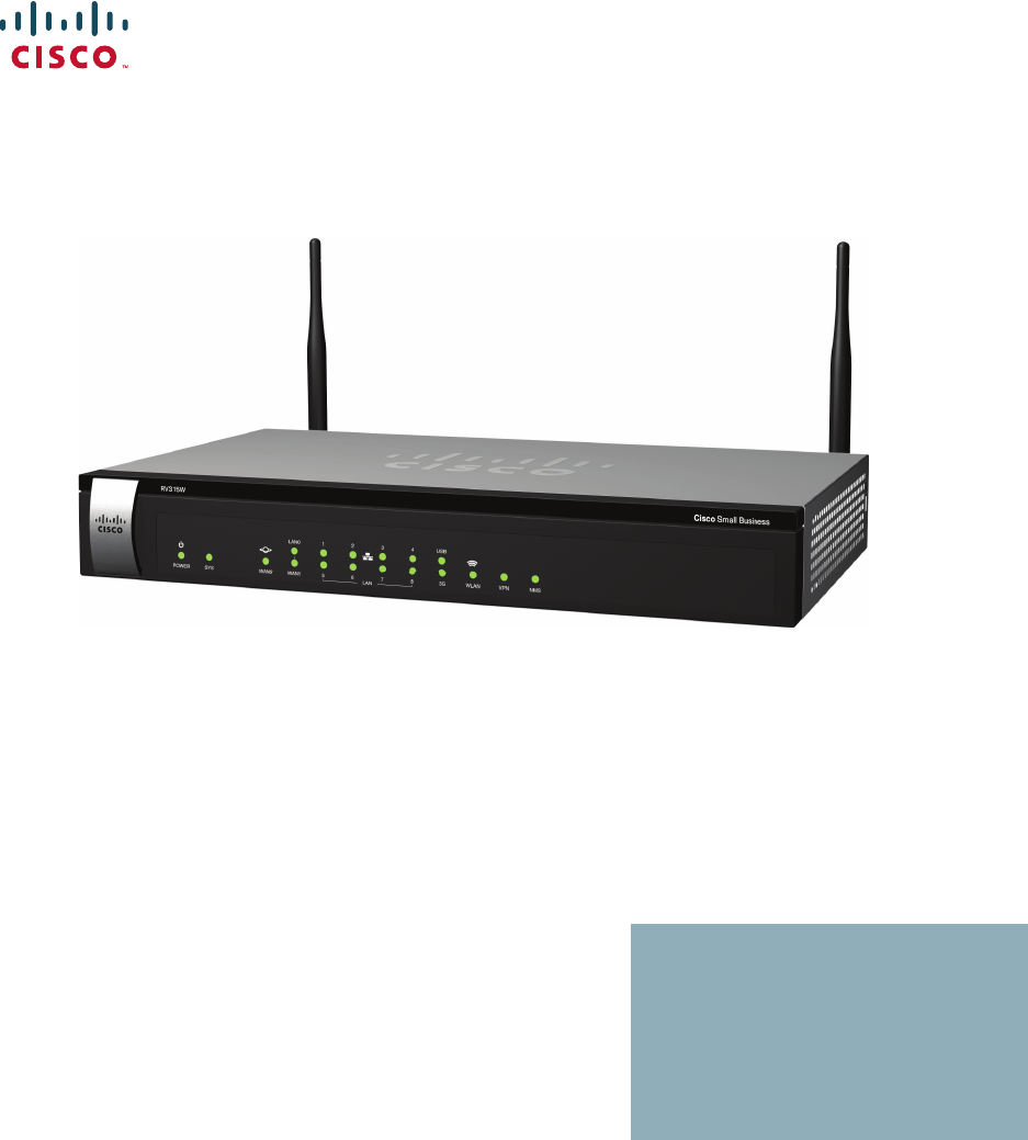
Before you use the RV315W, become familiar with the lights on the front panel and
the ports on the rear panel.
Front Panel
The lights are located on the front panel of the RV315W.

Getting Started
Product Overview
Cisco RV315W Broadband Wireless VPN Router Administration Guide 6
1
POWER •Solid green when the RV315W is powered on and is
operating normally.
•Off when the RV315W is powered off or the power has
problems.
SYS •Solid green when the RV315W is connected to the Internet
through your cable or DSL modem.
•Flashes green when the RV315W is attempting to connect
to the Internet, the RV315W cannot connect to the Internet,
or the system is upgrading the firmware.
•Solid red when the system has problems.
•Flashes red when the system is overloaded, such as the
CPU utilization or the memory utilization exceeds the
limitation.
•Off when there is no Internet connection.
WAN0 •Solid green when the RV315W is connected to the Internet
through the WAN0 port, but there is no traffic over this port.
•Flashes green when the RV315W is sending or receiving
data over the WAN0 port.
•Off when the WAN0 port has no connection.
WAN1 If the WAN1/LAN0 port on the back panel is set to a secondary
WAN interface (WAN1):
•Solid green when the RV315W is connected to the Internet
through the WAN1 port, but there is no traffic over this port.
•Flashes green when the RV315W is sending or receiving
data over the WAN1 port.
•Off when the WAN1 port has no connection.
LAN0 If the WAN1/LAN0 port on the back panel is set to an additional
LAN interface (LAN0):
•Solid green when the RV315W is connected to a device
through the LAN0 port, but there is no traffic over this port.
•Flashes green when the RV315W is sending or receiving
data over the LAN0 port.
•Off when the LAN0 port has no connection.

Getting Started
Product Overview
Cisco RV315W Broadband Wireless VPN Router Administration Guide 7
1
LAN1-8 The numbered lights correspond to the LAN ports on the back
panel of the RV315W.
•Solid green when the RV315W is connected to a device
through the corresponding port (LAN1 to 8), but there is no
traffic over that port.
•Flashes green when the RV315W is sending or receiving
data over the corresponding LAN port.
•Off when the corresponding LAN port has no connection.
USB •Solid green when a USB device is detected, but has no read
and write operations.
•Flashes green when a USB device is detected and has read
and write operations.
•Off when the RV315W does not detect a USB device.
3G •Solid green when the RV315W is connected to a 3G
wireless network, but there is no traffic over the 3G USB
port.
•Flashes green when the RV315W is sending or receiving
data over the 3G USB port.
•Off when the RV315W does not connect to a 3G wireless
network.
WLAN •Solid green when the wireless module is enabled, but there
is no traffic over the wireless network.
•Flashes green when the RV315W is sending or receiving
data on the wireless module.
•Off when the wireless module is disabled.
Getting Started
Product Overview
Cisco RV315W Broadband Wireless VPN Router Administration Guide 8
1
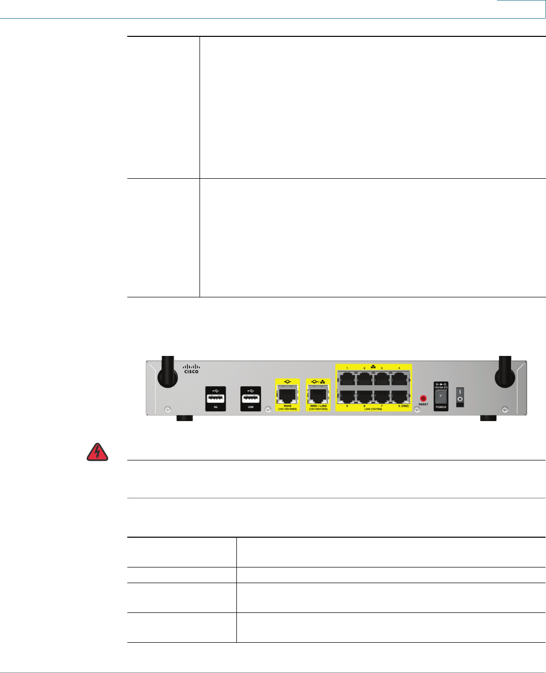
Back Panel
WARNING 33 cm minimum when the product is operated with a plug-in 3G USB device which
has maximum of 7 W ERP output power.
VPN •Solid green when there are active VPN tunnels, but there is
no VPN traffic.
•Flashes green when the RV315W is sending or receiving
data over the VPN tunnels.
•Flashes green once per two seconds when the RV315W is
attempting to establish a VPN tunnel, or the attempt of
establishing a new VPN tunnel fails.
•Off when there is no VPN connection.
NMS •Solid green when the RV315W is connected to an
upper-level Network Management System (NMS) but has no
operations.
•Flashes green when the RV315W is connected to an
upper-level NMS and has operations.
•Off when the RV315W does not connect to an upper-level
NMS.
3G USB Port Insert a 3G USB device into this port to connect your
RV315W to a 3G wireless network.
USB Port Reserved for future use.
WAN0 Port The WAN0 (Internet) port is connected to your Internet
device, such as a cable or DSL modem.
WAN1/LAN0 Port The WAN1/LAN0 port can be set to a secondary WAN
interface (WAN1) or an additional LAN interface (LAN0).

Getting Started
Product Overview
Cisco RV315W Broadband Wireless VPN Router Administration Guide 9
1
Default Settings
These are the default settings used when configuring your RV315W for the first
time.
NOTE Press and hold the RESET button for more than 5 seconds with a paper clip or a
pencil tip to reboot the unit and restore the factory defaults. Changes that you have
previously made to the RV315W settings are lost.
LAN1-8 Ports These ports provide a LAN connection to network devices,
such as PCs, print servers, or switches.
RESET The RESET button has two functions:
•Reboot: Press the RESET button for at least 1, but no
more than 5 seconds with a paper clip or a pencil tip
to reboot the unit.
•Restore to Factory Defaults: Press and hold the
RESET button for more than 5 seconds to reboot the
unit and restore to factory defaults. Changes that you
have previously made to the RV315W settings are
lost.
POWER (12VDC) The POWER port is where you connect the supplied power
adapter (12 V/3 A).
Power Switch Powers the unit on or off.
Parameter Default Value
Username cisco
Password cisco
LAN IP 192.168.1.1
DHCP Range 192.168.1.100 to 192.168.1.200
Getting Started
Mounting the RV315W
Cisco RV315W Broadband Wireless VPN Router Administration Guide 10
1
Mounting the RV315W
You can place your RV315W on a desktop or mount it on a wall.
Placement Tips
•Ambient Temperature—To prevent the RV315W from overheating, do not
operate it in an area that exceeds an ambient temperature of 104°F (40°C).
•Air Flow—Be sure that there is adequate air flow around the RV315W.
•Mechanical Loading—Be sure that the RV315W is level and stable to avoid
any hazardous conditions.
Place the RV315W horizontally on a flat surface so that it sits on its four rubber
feet.
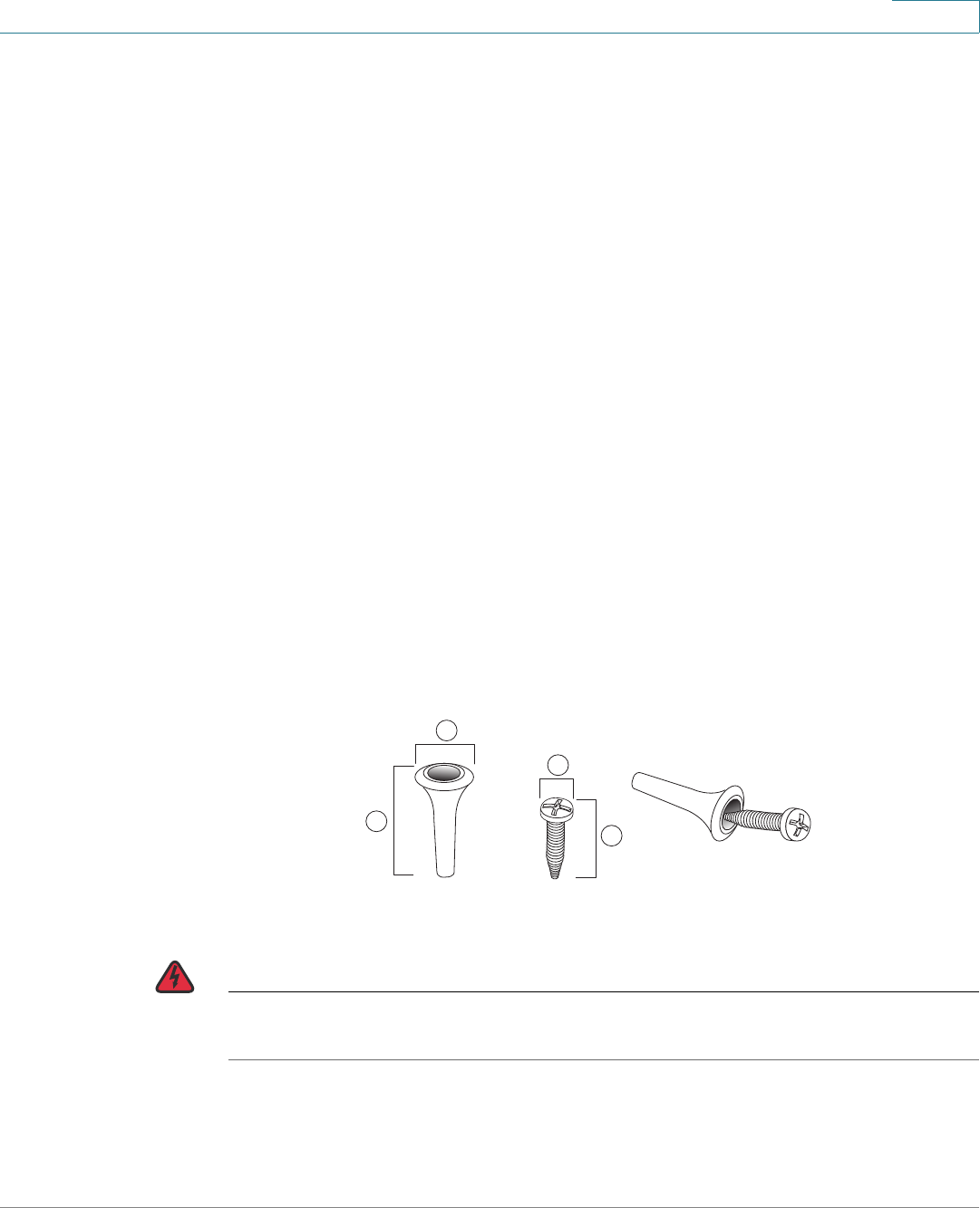
Wall-Mounting
The RV315W can be wall-mounted. The wall-mounting hardware is
user-supplied. The ports on the back panel must face either upward or downward
when mounting the RV315W to the wall. The recommended dimensions for the
mount kit are as follows:
WARNING Insecure mounting might damage the device or cause injury. Cisco is not
responsible for damages incurred by insecure wall-mounting.
18 mm/0.31 in 225 mm/0.98 in 36.5 mm/0.26 in 417.9 mm/0.7 in
1
2
4
3
196243

Getting Started
Connecting the RV315W
Cisco RV315W Broadband Wireless VPN Router Administration Guide 11
1
To mount the RV315W to the wall:
STEP 1 Determine where you want to mount the RV315W. Verify that the surface is
smooth, flat, dry, and sturdy.
STEP 2 Drill two pilot holes into the surface 5.9 inches (150 mm) apart.
STEP 3 Insert a screw into each hole, leaving a gap between the surface and the base of
the screw head of at least 0.1 inches (3 mm).
STEP 4 Place the RV315W wall-mount slots over the screws and slide the RV315W down
until the screws fit snugly into the wall-mount slots.
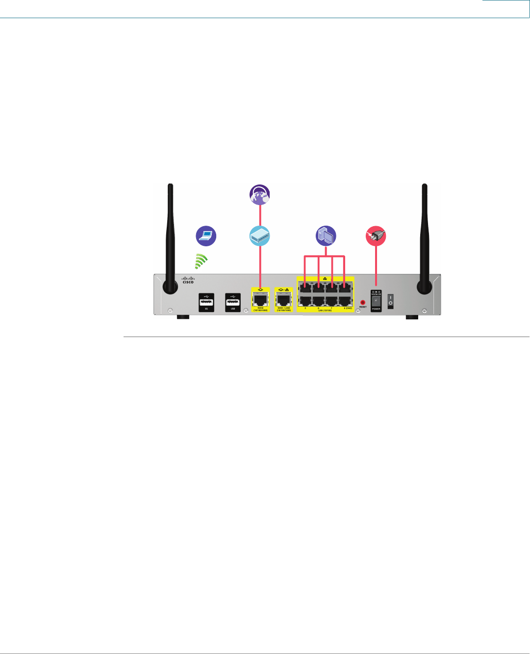
Connecting the RV315W
NOTE The wireless module of the RV315W is enabled by default. You can connect one
PC with an Ethernet cable or through a wireless connection to perform the initial
configuration. Use the default wireless network name (SSID) and pre-shared key
that are provided on the product label at the bottom of the RV315W to connect the
PC to your wireless network for the first time.
STEP 1 Power off all equipment, including the cable or DSL modem, the PC that you will
use to connect to the RV315W, and the RV315W.
STEP 2 Connect one end of an Ethernet cable to your cable or DSL modem. Connect the
other end to the WAN0 port on the back panel of the RV315W.
STEP 3 Connect one end of a different Ethernet cable to one of the LAN ports on the back
panel. Connect the other end to an Ethernet port on the PC that you will use to run
web-based Configuration Utility.
NOTE Skip this step if you want to connect the PC to the RV315W through a
wireless connection.
STEP 4 Connect the supplied power adapter to the POWER port on the back panel. Plug
the other end of the power adapter into an electrical outlet. Make sure that the
power switch is turned off.
NOTE Use only the power adapter that is supplied with the unit. Using a different
power adapter could damage the unit.
Getting Started
Getting Started with the Configuration
Cisco RV315W Broadband Wireless VPN Router Administration Guide 12
1
STEP 5 Power on all connected devices including the cable or DSL modem and the PC
and wait until the connections are active.
STEP 6 Power on the RV315W.
STEP 7 To connect the PC to your wireless network for the first time, you can configure the
wireless connection using the default SSID name and pre-shared key that are
provided on the product label.
A sample configuration is illustrated here.
Getting Started with the Configuration
You can use web-based Configuration Utility of the RV315W to view the system
information, configure the key parameters, upgrade system firmware, reboot the
unit, or restore the unit to its factory default settings.
Before You Begin
Before you begin to use web-based Configuration Utility, make sure that you have
a computer with Microsoft Internet Explorer 6.0 (or later) or Mozilla Firefox 3.0 (or
later).
NOTE The minimum recommended display resolution for the PC running the web browser
used to access the utility is 1024 x 768.
Power
Supply
Internet
Access
Devices Network
Devices
Wireless
Devices

Getting Started
Getting Started with the Configuration
Cisco RV315W Broadband Wireless VPN Router Administration Guide 13
1
Logging in to the Configuration Utility
To log in to the utility and launch the Setup Wizard to complete the initial
configuration:
STEP 1 Connect a computer to an available LAN port on the back panel. After you power
on the PC, your PC becomes a DHCP client of the RV315W and receives an IP
address in the 192.168.1.xxx range.
STEP 2 Start a web browser. In the Address bar, enter the default IP address of the
RV315W: 192.168.1.1.
STEP 3 When the login page appears, choose the language that you prefer to use in the
utility, and then enter the username and password.
The default administrator username is cisco. The default administrator password
is cisco. Both usernames and passwords are case sensitive.
For security purposes, change the default administrator password as soon as
possible. See Changing the Default Administrator Password for more
information.
STEP 4 Click Login.
STEP 5 Click Setup Wizard in the left-hand navigation pane. The Setup Wizard launches.
STEP 6 Follow the on-screen prompts to complete the initial configuration.
After the initial configuration is complete, you can configure other advanced
features. See the help pages for more information.
Using the Help System
The Configuration Utility provides a context-sensitive help file for all configuration
tasks. To view the Help page, click the Help link in the top right corner of the
screen. A new window opens with information about the page that you are
currently viewing.

Getting Started
Performing Basic Configuration Tasks
Cisco RV315W Broadband Wireless VPN Router Administration Guide 14
1
Performing Basic Configuration Tasks
We recommend that you complete the tasks in this section before you configure
the RV315W.
Changing the Default Administrator Password
The default administrator account (admin) has full privilege to set the configuration
and read the system status. For security purposes, we recommend that you
change the default administrator password after your first login.
To change the default administrative password:
STEP 1 Click System Management > User Management. The User Management page
opens.
STEP 2 Check the default administrator account (admin) and click Change Password.
STEP 3 Enter the following information:
•Old Password: Enter the current administrator password.
•New Password: Enter a new administrator password. Passwords are case
sensitive.
•Password Confirm: Enter the password again for confirmation.
STEP 4 Click OK to save your settings.
Upgrading Your Firmware After Your First Login
After you log in to web-based Configuration Utility for the first time, we
recommend that you upgrade your firmware to the latest version before you do
any other tasks.
NOTE This feature requires that you have an active WAN connection to access the
Internet.

Getting Started
Performing Basic Configuration Tasks
Cisco RV315W Broadband Wireless VPN Router Administration Guide 15
1
To upgrade the firmware:
STEP 1 Choose System Management > Firmware Upgrade. The Firmware Upgrade
page opens.
The following information is displayed:
•Device Model: Displays the device model.
•PID VID: Displays the product ID and version ID.
•Current Firmware Version: Displays the firmware version (primary
firmware) that the RV315W is currently using.
•Backup Firmware Version: Displays the firmware version (secondary
firmware) that is used as a backup. When you upgrade the firmware to a
newer version, the system first overwrites the secondary firmware with the
new version in the flash, and then reboots with the new firmware. The new
firmware becomes the primary firmware and the previous primary firmware
becomes the secondary firmware.
STEP 2 In the Download the latest firmware field, click Download to download the latest
version of the firmware from the specified website to your local PC. Make sure that
you have an active WAN connection.
STEP 3 In the Locate & select the upgrade file field, click Browse to locate and select the
downloaded firmware image from your local PC.
STEP 4 Click Upgrade.
After the new firmware image is validated, the new image is written to flash. The
RV315W will be automatically rebooted with the new firmware.

Getting Started
Performing Basic Configuration Tasks
Cisco RV315W Broadband Wireless VPN Router Administration Guide 16
1
Backing Up Your Configuration
At any point during the configuration process, you can back up your configuration.
Later, if you make changes that you want to abandon, you can easily restore the
saved configuration.
To back up your configuration:
STEP 1 Click System Management > Configuration Management. The Configuration
Management page opens.
STEP 2 To back up the settings currently used on your RV315W, click Backup
Configuration.
STEP 3 Select where to locate the configuration file, and then click OK.

2
Cisco RV315W Broadband Wireless VPN Router Administration Guide 17
Using the Setup Wizard
This chapter describes how to use the Setup Wizard to quickly configure the initial
settings of your RV315W. It includes the following sections:
•Starting the Setup Wizard
•Configuring WAN Connection
•Configuring Default LAN Settings
•Configuring Wireless Connection
•Completing the Setup Wizard
Starting the Setup Wizard
STEP 1 Click Setup Wizard in the left-hand navigation pane. The Setup Wizard launches.
STEP 2 If you are an expert, you can exit the Setup Wizard and click the menu in the left-
hand navigation pane to configure the specific feature directly. If you want to
continue, click Next to proceed to the WAN Configuration page. Or you can click
Exit to exit the Setup Wizard.
Configuring WAN Connection
From the WAN Configuration page you can configure the WAN connection by
using the information provided by your Internet Service Provider (ISP).
Depending on the requirements of your ISP, choose the Internet connection type
and configure the corresponding fields. The RV315W supports four types of
network addressing modes: DHCP, Static IP, PPPoE, and L2TP.

Using the Setup Wizard
Configuring WAN Connection
Cisco RV315W Broadband Wireless VPN Router Administration Guide 18
2
STEP 3 Choose WAN0 or WAN1 (only available when the WAN1/LAN0 port on the back
panel is set to a secondary WAN port) from the WAN Interface drop-down menu
to connect to the Internet.
STEP 4 Choose a proper network addressing method from the Internet Connection Type
drop-down menu and specify the corresponding settings.
The following table provides the configuration instruction for each Internet
connection type. Confirm that you have proper network information from your ISP
or a peer router to configure the RV315W to access the Internet.
Internet
Connection
Type
Configuration
DHCP Connection type often used with cable modems. Choose this
option if your ISP dynamically assigns an IP address on
connection.
Static IP Choose this option if your ISP provides you with a static
(permanent) IP address and does not assign it dynamically.
Use the corresponding information from your ISP to complete
the following fields:
•IP Address: Enter the IP address of the WAN port that
can be accessible from the Internet.
•Subnet Mask: Enter the IP address of the subnet mask.
•Default Gateway: Enter the IP address of default
gateway.
•Primary DNS Server: DNS servers map Internet
domain names to IP addresses. Enter the IP address of
the primary DNS server. You can get the DNS server
address from your ISP.
•Secondary DNS Server: (Optional) Enter the IP
address of the secondary DNS server.

Using the Setup Wizard
Configuring WAN Connection
Cisco RV315W Broadband Wireless VPN Router Administration Guide 19
2
PPPoE PPPoE uses Point-to-Point Protocol over Ethernet (PPPoE) to
connect to the Internet.
Choose this option if your ISP provides you with client
software, username, and password.
•User Name: Enter the username that is required to log
into the ISP.
•Password: Enter the password that is required to log
into the ISP.
•Service Name: Enter the name for the PPPoE service.
•Keep Alive: Choose one of the following options:
-Connect Idle Time: Let the RV315W disconnect
from the Internet after a specified period of
inactivity (Idle Time). This option is recommended if
your ISP fees are based on the time that you spend
online. If you choose this option, enter the idle time
in the field. The default value is 300 seconds.
-Keep Alive: Keep the connection always on,
regardless of the level of activity. This option is
recommended if you pay a flat fee for your Internet
service. If you choose this option, enter the interval
to automatically reestablish the WAN connection
after the connection is down. The default value is 30
seconds.
Internet
Connection
Type
Configuration

Using the Setup Wizard
Configuring WAN Connection
Cisco RV315W Broadband Wireless VPN Router Administration Guide 20
2
STEP 5 In the Enable VLAN area, click Enable when the ISP uses the VLAN ID to add the
tag to the users, and then enter the following information:
•VLAN ID: Enter the tag of the VLAN ID.
•802.1p Priority: Enter the value of the 802.1p priority.
L2TP Choose this option if you want to use Layer 2 Tunneling
Protocol (L2TP) to connect to the Internet.
Use the necessary information from your ISP to complete the
L2TP configuration:
•Auto Get IP: Enable or disable to automatically obtain
an IP address.
•L2TP Server IP Address: Enter the IP address of the
L2TP server.
•User Name: Enter the username that is required to log
into the L2TP server.
•Password: Enter the password that is required to log
into the L2TP server.
•Keep Alive: Choose one of the following options:
-Connect Idle Time: Let the RV315W disconnect
from the Internet after a specified period of
inactivity (Idle Time). This option is recommended if
your ISP fees are based on the time that you spend
online. If you choose this option, enter the idle time
in the field. The default value is 300 seconds.
-Keep Alive: Keep the connection always on,
regardless of the level of activity. This option is
recommended if you pay a flat fee for your Internet
service. If you choose this option, enter the interval
to automatically reestablish the WAN connection
after the connection is down. The default value is 30
seconds.
Internet
Connection
Type
Configuration

Using the Setup Wizard
Configuring Default LAN Settings
Cisco RV315W Broadband Wireless VPN Router Administration Guide 21
2
STEP 6 If you want to continue, click Next to proceed to the LAN Configuration page. If you
want to return to the previous page, click Back. If you want to exit the Setup
Wizard, click Exit.
Configuring Default LAN Settings
From the LAN Configuration page you can configure the default LAN settings of
the RV315W.
STEP 7 Enter the following information:
•VLAN: Select a VLAN from the drop-down menu. See Configuring LAN
Interfaces for more information on configuring the VLANs.
•IP Address: Enter the subnet IP address of the default LAN.
•Subnet Mask: Enter the subnet mask of the default LAN.
•DHCP Service: Check Enable to allow the RV315W to act as a DHCP server
and assign IP addresses to all devices that are connected to the LAN. Any
new DHCP client joining the LAN is assigned an IP address of the DHCP pool.
Check Disable to disable the DHCP server on the RV315W.
•Start IP: Enter the starting IP address of the DHCP pool if you enable the
DHCP server.
•End IP: Enter the ending IP address of the DHCP pool if you enable the DHCP
server.
•Lease Time: Enter the maximum connection time in minutes that a dynamic
IP address is “leased” to a network user. When the time elapses, the dynamic
IP address of the user is automatically renewed. The default is 0, indicates
that the lease time is 1 day.
STEP 8 If you want to continue, click Next to proceed to the Wireless Configuration page.
If you want to return to the previous page, click Back. If you want to exit the Setup
Wizard, click Exit.

Using the Setup Wizard
Configuring Wireless Connection
Cisco RV315W Broadband Wireless VPN Router Administration Guide 22
2
Configuring Wireless Connection
From the Wireless Configuration page you can configure the wireless network of
the RV315W and the security settings for the selected SSID.
STEP 9 Enter the following information:
•Current SSID: Select a SSID as the default wireless access point of the
RV315W.
•SSID Name: Displays the name of the selected SSID. You can edit the SSID
name. Enter a unique name for the SSID for identification.
•Enable Current SSID: Check Enable to enable this SSID, or check Disable
to disable the SSID.
•Security Mode: Choose the security mode and configure the
corresponding security settings. For security purposes, we strongly
recommend that you use WPA2 for wireless security. The following table
lists all available security modes:
Security Mode Configuration
Open Any wireless device that is in range can connect to the SSID.
This is the default setting but not recommended.

Using the Setup Wizard
Configuring Wireless Connection
Cisco RV315W Broadband Wireless VPN Router Administration Guide 23
2
WEP WEP encryption is an older encryption method that is not
considered to be secure and can easily be broken. Choose
this option only if you need to allow access to devices that do
not support WPA or WPA2.
If you choose this option, enter the following information:
•Authentication Type: Choose either Open System or
Shared key. The default is Open System.
•Key Length: Choose either 64 bits or 128 bits. The
default is 64 bits. The larger size keys provide stronger
encryption, which makes the key more difficult to
crack.
•Passphrase: If you want to generate WEP keys by
using a Passphrase, enter any alphanumeric phrase
(between 4 to 63 characters) and then click Generate
to generate 4 unique WEP keys. Select one key to use
as the key that devices must have to use the wireless
network.
•Key Index: Choose a key index as the default transmit
key. Key indexes 1 through 4 are available.
•Key 1-4: If a WEP Passphrase is not specified, a key
can be entered directly into one of the Key boxes. The
length of the key should be 5 ASCII characters (or 10
hex characters) for 64-bit encryption and 13 ASCII
characters (or 26 hex characters) for 128-bit
encryption.
Security Mode Configuration

Using the Setup Wizard
Configuring Wireless Connection
Cisco RV315W Broadband Wireless VPN Router Administration Guide 24
2
WPA-Personal Wi-Fi Protected Access (WPA) provides better security than
WEP because it uses dynamic key encryption. This standard
was implemented as an intermediate measure to replace
WEP, pending final completion of the 802.11i standard for
WPA2.
WPA-Personal supports Temporal Key Integrity Protocol
(TKIP) or Advanced Encryption System (AES) encryption
mechanisms for data encryption (default is TKIP). TKIP uses
dynamic keys and incorporates Message Integrity Code
(MIC) to provide protection against hackers. AES uses
symmetric 128-bit block data encryption.
If you choose this option, enter the following information:
•WPA Pre-Shared Key: The Pre-shared Key (PSK) is
the shared secret key for WPA. Enter a string of at least
8 characters to a maximum of 63 characters.
•WPA Key Renewal Timeout: Enter a value to set the
interval at which the key is refreshed for clients
associated to this SSID. A value of zero (0) indicates
that the key is not refreshed. The default value is 3600
seconds.
•WPA Encryption: Choose TKIP, AES, or TKIP+AES as
the encryption algorithm for data encryption. The
default is TKIP.
Security Mode Configuration

Using the Setup Wizard
Configuring Wireless Connection
Cisco RV315W Broadband Wireless VPN Router Administration Guide 25
2
WPA2-
Personal
WPA2 provides the best security for wireless transmissions.
This method implements the security standards specified in
the final version of 802.11i. WPA2-Personal always uses AES
encryption mechanism for data encryption.
If you choose this option, enter the following information:
•WPA Pre-Shared: The Pre-shared Key (PSK) is the
shared secret key for WPA. Enter a string of at least 8
characters to a maximum of 63 characters.
•WPA Key Renewal Timeout: Enter a value to set the
interval at which the key is refreshed for clients
associated to this SSID. A value of zero (0) indicates
that the key is not refreshed. The default value is 3600
seconds.
•WPA Encryption: Choose TKIP, AES, or TKIP+AES as
the encryption algorithm for data encryption. The
default is AES.
Security Mode Configuration

Using the Setup Wizard
Configuring Wireless Connection
Cisco RV315W Broadband Wireless VPN Router Administration Guide 26
2
WPA-
Enterprise
WPA-Enterprise uses WPA with RADIUS authentication. This
mode supports TKIP and AES encryption mechanisms
(default is TKIP) and requires the use of a RADIUS server to
authenticate users.
If you choose this option, enter the following information:
•WPA Key Renewal Timeout: Enter a value to set the
interval at which the key is refreshed for clients
associated to this SSID. A value of zero (0) indicates
that the key is not refreshed. The default value is 3600
seconds.
•WPA Encryption: Choose TKIP, AES, or TKIP+AES as
the encryption algorithm for data encryption. The
default is TKIP+AES.
•RADIUS Server IP Address: Enter the IP address of
the RADIUS server.
•RADIUS Server Port: Enter the port number of the
primary RADIUS server. The default value is 1812.
•RADIUS Server Key: Enter the key for authentication
used by the RADIUS server and the RV315W.
Security Mode Configuration

Using the Setup Wizard
Completing the Setup Wizard
Cisco RV315W Broadband Wireless VPN Router Administration Guide 27
2
STEP 10 If you want to continue, click Next to proceed to the Complete Setup Wizard page.
If you want to return to the previous page, click Back. If you want to exit the Setup
Wizard, click Exit.
Completing the Setup Wizard
From the Complete Setup Wizard page you can see the summary information for
all configurations.
STEP 11 If you want to return to the previous page, click Back. If you want to exit the Setup
Wizard, click Exit.
STEP 12 If the configuration is correct, click Finish to apply the settings and complete the
Setup Wizard configuration.
WPA2-
Enterprise
WPA2-Enterprise uses WPA2 with RADIUS authentication.
This mode always uses AES encryption mechanism for data
encryption and requires the use of a RADIUS server to
authenticate users.
If you choose this option, enter the following information:
•WPA Key Renewal Timeout: Enter a value to set the
interval at which the key is refreshed for clients
associated to this SSID. A value of zero (0) indicates
that the key is not refreshed. The default value is 3600
seconds.
•WPA Encryption: Choose TKIP, AES, or TKIP+AES as
the encryption algorithm for data encryption. The
default is AES.
•RADIUS Server IP Address: Enter the IP address of
the RADIUS server.
•RADIUS Server Port: Enter the port number of the
primary RADIUS server. The default value is 1812.
•RADIUS Server Key: Enter the key for authentication
used by the RADIUS server and the RV315W.
Security Mode Configuration

3
Cisco RV315W Broadband Wireless VPN Router Administration Guide 28
Viewing System Status
This chapter describes how to view real-time statistics and other information
about the RV315W. It includes the following sections:
•Device Information
•WAN Connection
•3G Wireless Connection
•LAN Interfaces
•Application Information
•Refresh Rate
Click System Summary. The System Summary page opens.
Device Information
The Device Information area displays the following information:
•Product Name: Product name of the unit.
•Model: Product model of the unit.
•VID: Version ID of the unit.
•PID: Product ID of the unit.
•Hardware Version: Hardware version that the device is currently using.
•Software Version: Firmware version that the device is currently using.
•System Up Time: Duration for which the system has been running.
•CPU Utilization: Current CPU utilization in percentage of the unit.
•Memory Utilization: Current memory utilization in percentage of the unit.

Viewing System Status
WAN Connection
Cisco RV315W Broadband Wireless VPN Router Administration Guide 29
3
WAN Connection
The WAN Connection area displays the following information:
•WANx Connection Status: Shows if the WAN interface or the WAN
subinterface is active or inactive for routing.
•WAN Connection Name: WAN connection name through a WAN interface
or a WAN subinterface.
•IP address: IP address of the WAN interface or the WAN subinterface.
3G Wireless Connection
The 3G Wireless Connection area displays the following information:
•3G Wireless Network: Displays whether the RV315W is connected to a 3G
wireless network or not.
•3G Modem Status: Displays whether a 3G USB dongle is detected or not.
The 3G USB dongle should be inserted into the 3G USB port on the back
panel.
•UIM Card Status: Displays whether the UIM card is detected or not. The
UIM card should be inserted into the 3G USB dongle.
•Signal Strength: Current 3G wireless signal strength if the RV315W is
connected to a 3G wireless network.
To see complete details of the 3G wireless connection:
STEP 1 Click More. The following information is displayed:
•3G Modem Information:
-3G Modem Status: Displays whether the RV315W is connected to a 3G
wireless network or not.
-Device Model: Model number of the detected 3G USB dongle.
-Manufacturer: Manufacturer name of the detected 3G USB dongle.
-Network Access License: Identification number of the network access
certificate.

Viewing System Status
LAN Interfaces
Cisco RV315W Broadband Wireless VPN Router Administration Guide 30
3
-Series Number: Series number of the 3G USB dongle.
-Hardware Version: Hardware version of the 3G USB dongle.
-Software Version: Software version that the 3G USB dongle is currently
using.
-PRL Version: PRL version of the 3G USB dongle.
•UIM Card Information:
-UIM Card Status: Current status of the UIM card.
-IMSI: IMSI number of the UIM card.
-Voltage: Current voltage of the UIM card.
•3G Network Information:
-Service Operator: Name of the 3G network service provider.
-Operating Status: Displays whether the RV315W is connected to a 3G
wireless network or not.
-Flow Rate: Current flow rate of the 3G wireless network.
-Transfer Rate: Current transfer rate of the 3G wireless network.
-Uptime: Duration for which the 3G wireless connection has been running.
-Signal Strength: The Wi-Fi signal strength of the 3G wireless connection.
STEP 2 Click Back to return to the System Summary page.
LAN Interfaces
The LAN Interfaces area displays the connection status for each LAN port.
WLAN Connection
The WLAN Connection area displays the following information:
•SSID: Name of the wireless access point.

Viewing System Status
Application Information
Cisco RV315W Broadband Wireless VPN Router Administration Guide 31
3
•Status: Shows if the SSID is enabled or disabled.
•Number of Connected PCs: Number of the client stations that are
connected to the SSID.
The wireless module of the RV315W is enabled by default. The RV315W provides
four virtual wireless networks, or four SSIDs (Service Set Identifiers).
To see complete details for all wireless clients that are connected to the RV315W:
STEP 1 Click View Connected Devices. The following information is displayed:
•Hostname: Hostname of the connected device.
•IP Address: IP address of the connected device.
•MAC Address: MAC address of the connected device.
•Lease Time: Duration for which the IP address is leased to the connected
device.
•Interface: Shows how the client is connected to the RV315W.
STEP 2 Click Back to return to the System Summary page.
Application Information
The Application Information area displays the following information for the
applications that are running on the RV315W, such as IPsec VPN:
•Application Name: Name of the running service or application.
•Status: Shows if the service or application is enabled or disabled.
Refresh Rate
Choose a refresh rate from the Refresh Rate drop-down menu, or choose Manual
to manually refresh the page at any time by clicking Refresh. This operation
causes the page to re-read the statistics from the RV315W and refresh the page.

4
Cisco RV315W Broadband Wireless VPN Router Administration Guide 32
Port Management
This chapter describes how to configure your Internet connection, LAN, wireless
network, and 3G wireless network. It includes the following sections:
•Configuring WAN Connections
•Configuring LAN
•Configuring Wireless Settings
•Configuring 3G Wireless Connection
Configuring WAN Connections
By default, the RV315W is configured to receive a public IP address from your ISP
automatically through DHCP. Depending on the requirements of your ISP, you may
need to modify the WAN settings to ensure the Internet connectivity.
Viewing WAN Connection Information
Click Port Settings > WAN > WAN Interface Settings. The WAN Interface
Settings page opens.
This page displays the following information:
Parameter Description
Port Number of the physical WAN interface, such as WAN0
or WAN1.
Connection Name WAN connection name through the physical WAN
interface or its subinterface.

Port Management
Configuring WAN Connections
Cisco RV315W Broadband Wireless VPN Router Administration Guide 33
4
Configuring WAN Connections
By default, the WAN1/LAN0 port on the back panel of the RV315W is set to a
secondary WAN interface so that the RV315W can support a second Internet
connection to ensure continuous connectivity or to increase available bandwidth
and balance traffic.
The RV315W allows you to add multiple subinterfaces on a physical WAN
interface. Each WAN subinterface can be used to set up an Internet connection but
only one of these connections can be used as the default route of the physical
WAN interface. Up to eight WAN subinterfaces can be added on the physical WAN
interfaces.
To configure a WAN connection through a physical WAN interface or its
subinterface:
STEP 1 Click Port Settings > WAN > WAN Interface Settings. The WAN Interface
Settings page opens.
STEP 2 To add a WAN subinterface on a physical WAN interface, click Create. The Add
WAN page opens.
NOTE To edit the settings of a physical WAN interface, click the Edit icon of the
corresponding WAN interface. The Edit WAN page opens.
STEP 3 In the Internet Connection Type area, select either Route Mode or Bridge Mode
for a WAN subinterface. The Route Mode is always selected for a physical WAN
interface.
STEP 4 If Route Mode is selected, select the radio button of the Internet connection type
that you use to connect to the Internet depending on your ISP requirements and
specify the corresponding settings of the selected Internet connection type.
Internet Connection
Type
Network addressing mode used to connect to the
Internet. See Configuring WAN Connection for more
information.
IP Address IP address of the WAN interface.
DNS IP address of the DNS server for the WAN interface.
Status Shows if the WAN interface is active or inactive for
routing.
Parameter Description

Port Management
Configuring WAN Connections
Cisco RV315W Broadband Wireless VPN Router Administration Guide 34
4
The following table provides the configuration instruction for each Internet
connection type. Confirm that you have proper network information from your ISP
or a peer router to configure the RV315W to access the Internet.
Internet
Connection
Type
Configuration
DHCP Connection type often used with cable modems. Choose this
option if your ISP dynamically assigns an IP address on
connection.
PPPoE PPPoE uses Point-to-Point Protocol over Ethernet (PPPoE) to
connect to the Internet. Choose this option if your ISP
provides you with client software, username, and password.
Use the necessary PPPoE information from your ISP to
complete the PPPoE configuration.
•User Name: Enter the username that is required to log
into the ISP.
•Password: Enter the password that is required to log
into the ISP.
•Service Name: Enter the name for the PPPoE service.
•Keep Alive: Choose one of the following options:
-Connect Idle Time: Choose this option to let the
RV315W disconnect from the Internet after a
specified period of inactivity (Idle Time). This option
is recommended if your ISP fees are based on the
time that you spend online. Enter the idle time in the
Maximum Idle Time field. The default value is 300
seconds.
-Keep Alive: Choose this option to keep the
connection always on, regardless of the level of
activity. This option is recommended if you pay a flat
fee for your Internet service. You can specify the
interval to automatically reestablish the WAN
connection after the connection is down. The
default value is 30 seconds.

Port Management
Configuring WAN Connections
Cisco RV315W Broadband Wireless VPN Router Administration Guide 35
4
PPPoE PPPoE uses Point-to-Point Protocol over Ethernet (PPPoE) to
connect to the Internet. Choose this option if your ISP
provides you with client software, username, and password.
Use the necessary PPPoE information from your ISP to
complete the PPPoE configuration.
•User Name: Enter the username that is required to log
into the ISP.
•Password: Enter the password that is required to log
into the ISP.
•Service Name: Enter the name for the PPPoE service.
•Keep Alive: Choose one of the following options:
-Connect Idle Time: Choose this option to let the
RV315W disconnect from the Internet after a
specified period of inactivity (Idle Time). This option
is recommended if your ISP fees are based on the
time that you spend online. Enter the idle time in the
Maximum Idle Time field. The default value is 300
seconds.
-Keep Alive: Choose this option to keep the
connection always on, regardless of the level of
activity. This option is recommended if you pay a flat
fee for your Internet service. You can specify the
interval to automatically reestablish the WAN
connection after the connection is down. The
default value is 30 seconds.

Port Management
Configuring WAN Connections
Cisco RV315W Broadband Wireless VPN Router Administration Guide 36
4
Static IP Choose this option if the ISP provides you with a static
(permanent) IP address and does not assign it dynamically.
Use the corresponding information from your ISP to complete
the following fields:
•IP Address: Enter the IP address of the WAN port that
can be accessible from the Internet.
•Subnet Mask: Enter the IP address of the subnet mask.
•Default Gateway: Enter the IP address of default
gateway.
•Primary DNS Server: DNS servers map Internet
domain names to IP addresses. Enter the IP address of
the primary DNS server. You can get the DNS server
addresses from your ISP.
•Secondary DNS Server: Enter the IP address of the
secondary DNS server.
Internet
Connection
Type
Configuration

Port Management
Configuring WAN Connections
Cisco RV315W Broadband Wireless VPN Router Administration Guide 37
4
STEP 5 In the Enable NAT field, check Enable to enable NAT, or check Disable to disable
NAT. Disable this feature if the WAN connection is only used for management
purpose.
STEP 6 In the Enable VLAN field, check Enable to enable VLAN if your ISP uses the VLAN
ID to identify the users. If you enable this feature, specify the VLAN ID and the
802.1p priority.
STEP 7 In the MTU field, choose Auto to use the default MTU size, or choose Manual if
you want to specify another size. If you choose Manual, enter the custom MTU
size in bytes.
L2TP Choose this option if you want to use Layer 2 Tunneling
Protocol (L2TP) to connect to the Internet.
Use the necessary information from your ISP to complete the
L2TP configuration:
•L2TP Server IP Address: Enter the IP address of the
L2TP server.
•User Name: Enter the username that is required to log
into the L2TP server.
•Password: Enter the password that is required to log
into the L2TP server.
•Keep Alive: Choose one of the following options:
-Connect Idle Time: Let the RV315W disconnect
from the Internet after a specified period of
inactivity (Idle Time). This option is recommended if
your ISP fees are based on the time that you spend
online. Enter the idle time in the Maximum Idle Time
field. The default value is 300 seconds.
-Keep Alive: Keep the connection always on,
regardless of the level of activity. This option is
recommended if you pay a flat fee for your Internet
service. You can specify the interval to automatically
reestablish the WAN connection after the
connection is down. The default value is 30
seconds.
Internet
Connection
Type
Configuration

Port Management
Configuring WAN Connections
Cisco RV315W Broadband Wireless VPN Router Administration Guide 38
4
STEP 8 In the Service Binding field, select one of the following service types for the WAN
connection:
•Management: Only use for management purpose.
•Internet: Only use for Internet access purpose.
•Management_Internet: Use for both management and Internet access
purposes.
•VoIP: Only use for VoIP traffic.
•IPTV: Only use for IPTV traffic.
•Other: Use for other purposes.
STEP 9 If you choose Bridge Mode, enter the following information:
•In the Enable VLAN filed, check the box to enable VLAN if your ISP uses the
VLAN ID to identify the users. If you enable this feature, specify the VLAN ID
and the 802.1p priority.
•In the Bridging Port area, specify the port as the subinterface's downstream
path.
STEP 10 Click OK to save your settings and return to the WAN Interface Settings page.
STEP 11 To edit the settings of a WAN connection, click Edit. To delete a WAN connection
through a WAN subinterface, click Delete.
Configuring Default Route of the Physical WAN Interface
If multiple WAN connections are defined on a physical WAN interface, you must
choose the default route of the physical WAN interface.
To configure the default route of the physical WAN interface:
STEP 1 Click Port Settings > WAN > WAN Interface Settings. The WAN Interface
Settings page opens.
STEP 2 In the Configure WAN Interface's Default Route area, select the default route
interface for each physical WAN interface.
STEP 3 Click OK to save your settings.

Port Management
Configuring WAN Connections
Cisco RV315W Broadband Wireless VPN Router Administration Guide 39
4
Configuring Dual WAN
If you have two ISP links, one for WAN0 and another for WAN1, you can configure
the WAN redundancy to determine how the two ISP links are used.
NOTE Dual WAN is only available when the WAN0/LAN1 port on the back panel is set to a
secondary WAN port (WAN1).
To configure dual WAN:
STEP 1 Click Port Settings > WAN > Dual WAN. The Dual WAN page opens.
STEP 2 In the Dual WAN area, enter the following information:
•Dual WAN: Click Enable to enable the Dual WAN feature, or click Disable to
disable it.
•Link Query Interval: The RV315W detects the WAN failure by pinging the
specified IP address. Enter the interval in seconds between two ping
detections. The default value is 60 seconds.
•Ping Timeout: If the connection to the ISP is down, the RV315W tries to
connect to the ISP after a specified timeout. Enter the timeout, in seconds, to
reconnect to the ISP. The default value is 5 seconds.
•Number of Ping Detections: Enter the number of pings. The default is 1.
•Recover the connection after x connection queries: Enter the number of
successful ping detections to recover the connection. The WAN connection
with the higher priority will be recovered.
STEP 3 In the Failover Detection area, specify the IP address used to detect the WAN
failure. By default, the RV315W pings the IP address of default WAN gateway with
the higher priority. If the default WAN gateway can be detected, the network
connection is active. You can also ping a specific remote host to detect the WAN
failure.
STEP 4 In the WAN Interface area, specify the priorities for the WAN interfaces, including
the 3G USB port:
•Interface: Name of the WAN interface.
•Status: Connection status of the WAN interface.
•Priority: Specify the priority of the WAN interface.
STEP 5 In the WAN Interface Details area, view the following information of the WAN
interfaces:
Port Management
Configuring WAN Connections
Cisco RV315W Broadband Wireless VPN Router Administration Guide 40
4
•Interface: Name of the WAN interface.
•IP Address: IP address of the WAN interface.
•Subnet Mask: Subnet mask of the WAN interface.
•Gateway: Default gateway IP address of the WAN interface.
STEP 6 In the Load Balancing area, check Enable to enable Load Balancing to distribute
the bandwidth to two WAN ports by the weighted percentages.
STEP 7 In the Load Balancing Control area, specify the weighted percentage for each
WAN, such as 50% bandwidth for WAN0, 50% bandwidth for WAN1, and 0% for
USB_3G, which indicates that 50% bandwidth is distributed to WAN0 and 50%
bandwidth is distributed to WAN1. The value of zero (0) indicates that Load
Balancing is disabled on the 3G USB interface.
STEP 8 Click OK to apply your settings.
Configuring WAN1/LAN0 Interface
The WAN1/LAN0 port on the back panel of the RV315W can be configured to a
secondary WAN port (WAN1) or an additional LAN port (LAN0).
STEP 1 Click Port Settings > WAN > WAN1/LAN0 Interface Settings. The WAN1/LAN0
Interface Settings page opens.
STEP 2 Select LAN0 to set this port to an additional LAN port, or select WAN1 to set this
port to a secondary WAN port.
STEP 3 Click OK to apply your settings.
!
CAUTION Changing the port type of the WAN1/LAN0 ports requires the RV315W to be
rebooted. Note that changing the port type from WAN1 to LAN0 will reboot the
RV315W with the factory default settings. The previous settings that you made on
the RV315W will be lost.

Port Management
Configuring LAN
Cisco RV315W Broadband Wireless VPN Router Administration Guide 41
4
Configuring LAN
A virtual LAN (VLAN) is a group of endpoints in a network that are associated by
function or other shared characteristics. Unlike LANs, which are usually
geographically based, VLANs can group endpoints without regard to the physical
location of the equipment or users.
The VLANs allow you to segregate the network into LANs that are isolated from
one another. Any PC that is connected to the specified LAN port is on a separate
VLAN and cannot access other VLANs.
Configuring LAN Interfaces
Use the LAN Interface Settings page to configure the settings of the LAN
interfaces.
To configure the LAN interface settings:
STEP 1 Click Port Settings > LAN > LAN Interface Settings. The LAN Interface Settings
page opens.
STEP 2 In the VLAN Interface Settings area, enter the following information:
•Select VLAN: Select a VLAN that you want to configure from the drop-down
menu. The default is VLAN1. You can add new VLANs in the VLAN Settings
page and assign the physical LAN ports to the specified VLANs. See
Configuring LAN Interfaces for more information.
•IP Address: Enter the subnet IP address for the VLAN.
•Netmask: Enter the subnet mask for the VLAN.
•DHCP Server: Check Enable to allow the RV315W to act as a DHCP server
and assign IP addresses to all devices that are connected to the LAN. Any
new DHCP client joining the LAN is assigned an IP address of the DHCP pool.
Check Disable to disable the DHCP server on the RV315W.
•Starting IP: Enter the starting IP address of the DHCP pool if you enable the
DHCP server.
•Ending IP: Enter the ending IP address of the DHCP pool if you enable the
DHCP server.

Port Management
Configuring LAN
Cisco RV315W Broadband Wireless VPN Router Administration Guide 42
4
•Lease Time: Enter the maximum connection time that a dynamic IP address
is “leased” to a network user. When the time elapses, the user is
automatically renewed the dynamic IP address. The default value is 1 day.
•Default Gateway: Enter the IP address for default gateway.
•DNS Agent: Check Enable to enable the DNS agent feature, or check
Disable to disable this feature.
•DNS1: Enter the IP address of the primary DNS server.
•DNS2: Optionally, enter the IP address of the secondary DNS server.
•Address Reservation: Check Enable to allow you to reserve some IP
addresses of the DHCP pool for specific hosts, or check Disable to disable
this feature. If you enable this feature, enter the following information:
-Host Name: Enter the name of the host for identification.
-Reserved IP Address: Enter the IP address that you want to reserve for
the specific host.
-MAC Address: Enter the MAC address of the host.
Click Add to add it in the list of the Reserved Hosts.
STEP 3 Click OK to apply your settings.
Configuring VLAN Settings
Use the VLAN Settings page to create new VLANs and assign physical LAN ports
to the specified VLANs.
To c r e a t e a n e w V L A N :
STEP 1 Click Port Settings > LAN > VLAN Settings. The VLAN Settings page opens.
STEP 2 To create a new VLAN, click Create and enter a unique identification number for
the VLAN in the VLAN ID field. The VLAN1 and VLAN2 are reserved.
STEP 3 In the VLAN Settings area, assign physical LAN ports to the specified VLAN.
STEP 4 Click OK to apply your settings.
STEP 5 To edit the settings of the VLAN, select the VLAN from the drop-down menu, and
then change the physical ports that are mapped to the VLAN. To delete a VLAN,

Port Management
Configuring Wireless Settings
Cisco RV315W Broadband Wireless VPN Router Administration Guide 43
4
click Delete, enter the VLAN ID in the VLAN ID field, and then click OK. The
reserved VLAN1 and VLAN2 cannot be deleted.
Configuring Wireless Settings
The wireless module of the RV315W is enabled by default. To connect to the
default wireless network of the RV315W for the first time, use the default wireless
network name (SSID) and pre-shared key that are provided on the product label at
the bottom of the RV315W.
Configuring Wireless Radio Settings
To configure the wireless radio settings:
STEP 1 Click Port Settings > WLAN Settings. The WLAN Settings page opens.
STEP 2 In the WLAN Radio Settings area, enter the following information:
•Radio: Check Enable to turn the wireless radio on, or check Disable to turn
the wireless radio off. The wireless radio is turned on by default.
•Wireless Network Mode: Choose one of the following options:
-802.11b/g/n Mixed: Choose this option if you have Wireless-N,
Wireless-B, and Wireless-G devices in your network. This is the default
setting (recommended).
-802.11b/g Mixed: Choose this option if you have Wireless-B and
Wireless-G devices in your network.
-802.11b: Choose this option if you have only Wireless-B devices in your
network.
-802.11g: Choose this option if you have only Wireless-G devices in your
network.
-802.11n: Choose this option if you have only Wireless-N devices in your
network.
•Wireless Band Selection: Select the wireless bandwidth on your network
(20 MHz, 40 MHz, or Auto).

Port Management
Configuring Wireless Settings
Cisco RV315W Broadband Wireless VPN Router Administration Guide 44
4
•Wireless Channel: Choose the wireless channel from the drop-down menu
or choose Auto to let the system determine the optimal channel to use based
on the environmental noise levels for the available channels.
-Select any channel from 1 to 13 channels when the wireless bandwidth
is set to 20 MHz.
-Select any channel from 3 to 11 channels when the wireless bandwidth
is set to 40 MHz (the default is 11 channel).
•Wi-Fi Power: Select the Wi-Fi power on your network. The default value is
High.
•Station Isolation: Check so that the wireless clients on the same SSID will
be unable to see each other.
•Wireless QoS: Check to enable WiFi MultiMedia (WMM), or uncheck to
disable this feature.
STEP 3 Click OK to apply your settings.
Configuring Wireless Security
The RV315W provides four virtual wireless networks.
To configure the settings for a wireless network:
STEP 1 Click Port Settings > WLAN Settings. The WLAN Settings page opens.
The Wireless table displays the following information for a wireless network:
•SSID Name: Name of the SSID.
•Security Mode: Security settings of the SSID.
•Status: Shows whether the SSID is enabled or disabled.
STEP 2 To enable a SSID, check the corresponding SSID and click Enable.
STEP 3 To disable a SSID, check the corresponding SSID and click Disable.
STEP 4 To edit the settings of a SSID, check the corresponding SSID and click Edit.
STEP 5 Enter the following information:
•SSID Name: Enter the name of the wireless network.

Port Management
Configuring Wireless Settings
Cisco RV315W Broadband Wireless VPN Router Administration Guide 45
4
•SSID Broadcast: Check to enable SSID broadcast and broadcast the SSID
in its beacon frames. All wireless devices within range are able to see the
SSID when they scan for available networks. Uncheck to prevent auto-
detection of the SSID. In this case, users must know the SSID to set up a
wireless connection to this SSID.
•Allow Remote Management: Check to allow you to remotely access the
RV315W through the wireless network and configure the settings of the
RV315W.
•User Limit: Specify the maximum number of users that can simultaneously
connect to this SSID. Enter a value in the range of 0 to 30. The default value
is zero (0), which indicates that there is no limit for this SSID.
•Security Mode: Select one of the following security modes for the wireless
network and configure the corresponding security settings. For security
purposes, we strongly recommend that you use WPA2 for wireless security.
Security
Mode
Configuration
Open Any wireless device that is in range can connect to the SSID.
This is the default setting but not recommended.

Port Management
Configuring Wireless Settings
Cisco RV315W Broadband Wireless VPN Router Administration Guide 46
4
WEP Wired Equivalent Privacy (WEP) is a data encryption protocol
for 802.11 wireless networks. All wireless stations and SSIDs
on the network are configured with a static 64-bit or 128-bit
Shared Key for data encryption. The higher the bit for data
encryption, the more secure for your network.
WEP encryption is an older encryption method that is not
considered to be secure and can easily be broken. Choose
this option only if you need to allow access to devices that do
not support WPA or WPA2.
If you choose this option, enter the following information:
•Authentication Type: Choose either Open System or
Shared key. The default is Open System.
•Encryption: Choose the encryption type: 64 bits (10
hex digits), 64 bits (5 ASCII), 128 bits (26 hex digits), or
128 bits (13 ASCII). The default is 64 bits (10 hex digits).
The larger size keys provide stronger encryption, thus
making the key more difficult to crack.
•Passphrase: If you want to generate WEP keys by
using a Passphrase, enter any alphanumeric phrase
(between 4 to 63 characters) and then click Generate
to generate 4 unique WEP keys. Select one key to use
as the key that devices must have to use the wireless
network.
•Default Transmit Key: Choose a key index as the
default transmit key. Key indexes 1 through 4 are
available.
•Key 1-4: If a WEP Passphrase is not specified, a key
can be entered directly into one of the Key boxes. The
length of the key should be 5 ASCII characters (or 10
hex characters) for 64-bit encryption and 13 ASCII
characters (or 26 hex characters) for 128-bit
encryption.
Security
Mode
Configuration

Port Management
Configuring Wireless Settings
Cisco RV315W Broadband Wireless VPN Router Administration Guide 47
4
WPA-Personal Wi-Fi Protected Access (WPA) provides better security than
WEP because it uses dynamic key encryption. This standard
was implemented as an intermediate measure to replace
WEP, pending final completion of the 802.11i standard for
WPA2.
WPA-Personal supports Temporal Key Integrity Protocol
(TKIP) or Advanced Encryption System (AES) encryption
mechanisms for data encryption (default is TKIP). TKIP uses
dynamic keys and incorporates Message Integrity Code (MIC)
to provide protection against hackers. AES uses symmetric
128-bit block data encryption.
If you choose this option, enter the following information:
•WPA Pre-Shared: The Pre-shared Key (PSK) is the
shared secret key for WPA. Enter a string of at least 8
characters to a maximum of 63 characters.
•Key Renewal Timeout: Enter a value to set the interval
at which the key is refreshed for clients associated to
this SSID. A value of zero (0) indicates that the key is not
refreshed. The default value is 3600 seconds.
•Encryption: Choose TKIP, AES, or TKIP+AES as the
encryption algorithm for data encryption. The default is
TKIP.
Security
Mode
Configuration

Port Management
Configuring Wireless Settings
Cisco RV315W Broadband Wireless VPN Router Administration Guide 48
4
WPA2-
Personal
WPA2 provides the best security for wireless transmissions.
This method implements the security standards specified in
the final version of 802.11i.
WPA2-Personal always uses AES encryption mechanism for
data encryption.
If you choose this option, enter the following information:
•WPA Pre-Shared: The Pre-shared Key (PSK ) is the
shared secret key for WPA. Enter a string of at least 8
characters to a maximum of 63 characters.
•Key Renewal Timeout: Enter a value to set the interval
at which the key is refreshed for clients associated to
this SSID. A value of zero (0) indicates that the key is not
refreshed. The default value is 3600 seconds.
•Encryption: Choose TKIP, AES, or TKIP+AES as the
encryption algorithm for data encryption. The default is
AES.
Security
Mode
Configuration

Port Management
Configuring Wireless Settings
Cisco RV315W Broadband Wireless VPN Router Administration Guide 49
4
WPA-
Enterprise
WPA-Enterprise uses WPA with RADIUS authentication. This
mode supports TKIP and AES encryption mechanisms
(default is TKIP) and requires the use of a RADIUS server to
authenticate users.
If you choose this option, enter the following information:
•Key Renewal Timeout: Enter a value to set the interval
at which the key is refreshed for clients associated to
this SSID. A value of zero (0) indicates that the key is not
refreshed. The default value is 3600 seconds.
•Encryption: Choose TKIP, AES, or TKIP+AES as the
encryption algorithm for data encryption. The default is
TKIP+AES.
•RADIUS Server IP Address: Enter the IP address of
the RADIUS server.
•RADIUS Server Port: Enter the port number of the
primary RADIUS server. The default value is 1812.
•RADIUS Server Key: Enter the key for authentication
used by the RADIUS server and the RV315W.
Security
Mode
Configuration

Port Management
Configuring Wireless Settings
Cisco RV315W Broadband Wireless VPN Router Administration Guide 50
4
STEP 6 Click OK to apply your settings.
WPA2-
Enterprise
WPA2-Enterprise uses WPA2 with RADIUS authentication.
This mode always uses AES encryption mechanism for data
encryption and requires the use of a RADIUS server to
authenticate users.
If you choose this option, enter the following information:
•Key Renewal Timeout: Enter a value to set the interval
at which the key is refreshed for clients associated to
this SSID. A value of zero (0) indicates that the key is not
refreshed. The default value is 3600 seconds.
•Encryption: Choose TKIP, AES, or TKIP+AES as the
encryption algorithm for data encryption. The default is
AES.
•RADIUS Server IP Address: Enter the IP address of
the RADIUS server.
•RADIUS Server Port: Enter the port number of the
primary RADIUS server. The default value is 1812.
•RADIUS Server Key: Enter the key for authentication
used by the RADIUS server and the RV315W.
Security
Mode
Configuration

Port Management
Configuring 3G Wireless Connection
Cisco RV315W Broadband Wireless VPN Router Administration Guide 51
4
Configuring 3G Wireless Connection
The RV315W supports the 3G wireless connection capability. To connect to a 3G
wireless network, insert an applicable 3G USB dongle into the 3G interface on the
back panel of the RV315W, and then configure the settings of the 3G wireless
network through web-based Configuration Utility. See the latest datasheet to get
the list of 3G USB dongle models supported by the RV315W.
To configure the settings of the 3G wireless network:
STEP 1 Click Port Settings > 3G Interface Settings. The 3G Interface Settings page
opens.
STEP 2 Enter the following information:
•3G Modem: Displays whether the RV315W is detected a 3G USB dongle.
The 3G USB dongle should be inserted into the 3G USB port on the back
panel.
•Dial Settings: Select either Auto or Manual to detect the settings of the 3G
USB dongle. If you select Auto, the RV315W automatically detects the
settings of the 3G USB dongle. If you select Manual, you need to manually
specify the following settings:
-APN: Enter the APN provided by the 3G wireless network service
provider.
-Username: Enter the username provided by the 3G wireless network
service provider.
-Password: Enter the password provided by the 3G wireless network
service provider.
-Dial String: Enter the dial string provided by the 3G wireless network
service provider.
•Dial Method: Select either Auto or Manual to dial in the 3G wireless
network.
•Keep Alive: If you select Auto, choose one of the following options:
-Connect Idle Time: Choose this option to let the RV315W disconnect
from the 3G wireless network after a specified period of inactivity (Idle
Time). This option is recommended if your ISP fees are based on the time
that you spend online. Enter the idle time in the Maximum Idle Time field.
The default value is 5 seconds.

Port Management
Configuring 3G Wireless Connection
Cisco RV315W Broadband Wireless VPN Router Administration Guide 52
4
-Keep Alive: Choose this option to keep the connection always on,
regardless of the level of activity. This option is recommended if you pay
a flat fee for your Internet service. You can specify the interval to
automatically re-dial in the 3G wireless network after the connection is
down. The default value is 30 seconds.
•Manual Dial: If you select Manual, click Connect to manually dial in the 3G
wireless network. To manually disconnect the 3G wireless connection, click
Disconnect.
•Status: Shows whether the RV315W is connected to a 3G wireless network
or not.
STEP 3 Click OK to apply your settings.

5
Cisco RV315W Broadband Wireless VPN Router Administration Guide 53
Networking
This chapter describes how to configure other network settings of the RV315W. It
includes the following sections:
•Configuring DDNS
•Configuring ALG
•Configuring Port Forwarding
•Configuring Port Triggering
•Configuring DMZ
•Configuring UPnP
•Configuring Port Mirroring
•Configuring Routing
•Configuring IGMP
Configuring DDNS
Dynamic DNS (DDNS) is an Internet service that allows routers with varying public
IP addresses to be located using Internet domain names. If your ISP has not
provided you with a static IP and your WAN connection is configured to use DHCP
to obtain an IP address dynamically, then DDNS provides the domain name to map
the dynamic IP address for your website. To use DDNS, you must set up an
account with a DDNS provider such as DynDNS.org or TZO.
To configure a DDNS service:
STEP 1 Click Networking > DDNS. The DDNS page opens.
STEP 2 Click Create to add a DDNS service.
STEP 3 Enter the following information:

Networking
Configuring ALG
Cisco RV315W Broadband Wireless VPN Router Administration Guide 54
5
•Service Provider: Specify the provider for your DDNS service. You can
choose either DynDNS.org or TZO.
•Domain Name: Enter the complete domain name of the DDNS service.
•Username: Enter the username of the account that you registered in the
DDNS provider.
•Password: Enter the password of the account that you registered in the
DDNS provider.
STEP 4 Click OK to save your settings.
STEP 5 To edit a DDNS service, select the corresponding DDNS service and click the Edit
icon. To delete a DDNS service, select the corresponding DDNS service and click
the Delete icon.
Configuring ALG
The RV315W can function as an Application Level Gateway (ALG) to allow certain
NAT incompatible applications (such as SIP or H.323) to operate properly through
the RV315W.
To configure ALG:
STEP 1 Click Networking > ALG. The ALG page opens.
STEP 2 Check the box of a protocol to enable the ALG support. The RV315W supports
ALG for GRE, SIP, H.323, IPSEC, L2TP, RTSP and NAT Passthrough.
STEP 3 Click OK to save your settings.

Networking
Configuring Port Forwarding
Cisco RV315W Broadband Wireless VPN Router Administration Guide 55
5
Configuring Port Forwarding
Port forwarding forwards a TCP/IP packet traversing a Network Address
Translator (NAT) gateway to a predetermined network port on a host within a NAT-
masqueraded, typically private network based on the port number on which it
was received at the gateway from the originating host.
Configuring Single Port Forwarding
To add a single port forwarding rule:
STEP 1 Click Networking > Port Forwarding > Single Port Forwarding. The Single Port
Forwarding page opens.
STEP 2 Enter the following information:
•Interface: Select a WAN interface or the 3G interface for this single port
forwarding rule.
•Protocol: Select either TCP or UDP protocol for this single port forwarding
rule.
•External Port: Specify the port number that triggers this rule when a
connection request from outgoing traffic is made. You can choose a
predefined option (such as finger, ftp, nntppop3, smtp, telnet, or http) to use
its default port value or choose Other to manually specify the external port
used by the application.
•Internal IP Address: Enter the IP address of the internal server.
•Internal Port: Specify the port number used by the remote system to
respond to the request that it receives. You can choose a predefined option
(such as finger, ftp, nntppop3, smtp, telnet, or http) to use its default port
value or choose Other to manually specify the internal port used by the
application.
•Status: Check Enable to enable this single port forwarding rule, or check
Disable to disable this rule.
STEP 3 Click Add to add this single port forwarding rule in the list.
STEP 4 To edit a single port forwarding rule, select the corresponding rule and click the
Edit icon. To delete a single port forwarding rule, select the corresponding rule

Networking
Configuring Port Forwarding
Cisco RV315W Broadband Wireless VPN Router Administration Guide 56
5
and click the Delete icon. To delete multiple single port forwarding rules at a time,
select the corresponding rules and click the Delete button.
Configuring Port Range Forwarding
To configure a port range forwarding rule:
STEP 1 Click Networking > Port Forwarding > Port Range Forwarding. The Port Range
Forwarding page opens.
STEP 2 Enter the following information:
•Interface: Select a WAN interface or the 3G interface for this port range
forwarding rule.
•Protocol: Select either TCP or UDP protocol for this port range forwarding
rule.
•Port Range: Specify the starting port and ending port to forward.
•Internal IP Address: Enter the IP address of the internal server.
•Status: Check Enable to enable this port range forwarding rule, or check
Disable to disable this rule.
STEP 3 Click Add to add this port range forwarding rule in the list.
STEP 4 To edit a port range forwarding rule, select the corresponding rule and click the
Edit icon. To delete a port range forwarding rule, select the corresponding rule and
click the Delete icon. To delete multiple port range forwarding rules at a time,
select the corresponding rules and click the Delete button.

Networking
Configuring Port Triggering
Cisco RV315W Broadband Wireless VPN Router Administration Guide 57
5
Configuring Port Triggering
Port triggering allows devices on the LAN or DMZ to request one or more ports to
be forwarded to them. Port triggering waits for an outbound request from the LAN/
DMZ on one of the defined outgoing ports, and then opens an incoming port for
that specified type of traffic.
Port triggering is a form of dynamic port forwarding while an application is
transmitting data over the opened outgoing or incoming ports. Port triggering
opens an incoming port for a specific type of traffic on a defined outgoing port.
Port triggering is more flexible than static port forwarding (available when
configuring firewall rules) because a rule does not have to reference a specific
LAN IP or IP range. Ports are also not left open when not in use, which provides a
level of security that port forwarding does not offer.
To add a port triggering rule:
STEP 1 Click Networking > Port Triggering. The Port Triggering page opens.
STEP 2 Enter the following information:
•WAN Port: Select the WAN interface to configure port triggering for.
•LAN Port: Select the LAN port to configure port triggering for.
•Protocol: Select either TCP or UDP protocol.
•Triggering Range: Enter the port number or a range of port numbers that will
trigger this rule when a connection request from outgoing traffic is made. If
the outgoing connection uses only one port, enter the same port number in
both fields.
•Forwarding Range: Enter the port number or a range of port numbers used
by the remote system to respond to the request that it receives. If the
incoming connection uses only one port, then specify the same port number
in both fields.
•Status: Check Enable to enable the port triggering rule, or check Disable to
disable this rule.
STEP 3 Click Add to add this port triggering rule in the list.
STEP 4 To edit a port triggering rule, select the corresponding rule and click the Edit icon.
To delete a port triggering rule, select the corresponding rule and click the Delete

Networking
Configuring DMZ
Cisco RV315W Broadband Wireless VPN Router Administration Guide 58
5
icon. To delete multiple port triggering rules at a time, select the corresponding
rules and click the Delete button.
Configuring DMZ
This section describes how to configure the software DMZ and hardware DMZ
features.
Configuring Software DMZ
To configure software DMZ:
STEP 1 Click Networking > DMZ > Software DMZ. The Software DMZ page opens.
STEP 2 To create a DMZ rule, enter the following information:
•DMZ Status: Check Enable to enable this DMZ rule, or check Disable to
disable this DMZ rule.
•External IP: Enter the external IP address.
•Internal IP: Enter the IP address of the internal server in the DMZ network.
•Binding Interface: Select the interface for this DMZ rule.
STEP 3 Click OK to save your settings.
STEP 4 To edit a software DMZ rule, select the corresponding rule and click the Edit icon.
To delete a software DMZ rule, select the corresponding rule and click the Delete
icon.

Networking
Configuring UPnP
Cisco RV315W Broadband Wireless VPN Router Administration Guide 59
5
Configuring Hardware DMZ
The hardware DMZ feature sets the LAN8 port on the back panel to a DMZ port.
This feature is only available when you use Static IP or DHCP to connect to the
Internet.
To configure the hardware DMZ:
STEP 1 Click Networking > DMZ > Hardware DMZ. The Hardware DMZ page opens.
STEP 2 Check Enable to enable the hardware DMZ feature and set the LAN8 part on the
back panel to a DMZ port.
STEP 3 Click Create to create a DMZ rule.
STEP 4 Enter the following information:
•Status: Check Enable to enable this DMZ rule, or check Disable to disable
this DMZ rule.
•Public IP: Enter the public IP address.
•WAN Interface: Select a WAN interface for this DMZ rule.
STEP 5 Click OK to save your settings.
STEP 6 To edit a hardware DMZ rule, select the corresponding rule and click the Edit icon.
To delete a hardware DMZ rule, select the corresponding rule and click the Delete
icon.
Configuring UPnP
Universal Plug and Play (UPnP) allows for automatic discovery of devices that can
communicate with your RV315W.
To enable or disable UPnP on the RV315W:
STEP 1 Click Networking > UPnP. The UPnP page opens.
STEP 2 Click Enable to enable UPnP, or click Disable to disable UPnP. If UPnP is disabled,
the RV315W will not allow for automatic device configuration.

Networking
Configuring Port Mirroring
Cisco RV315W Broadband Wireless VPN Router Administration Guide 60
5
STEP 3 Click OK to save your settings.
Configuring Port Mirroring
Port Mirroring allows traffic on one port to be visible on other ports. This feature is
useful for debugging or traffic monitoring.
To configure Port Mirroring:
STEP 1 Click Networking > Port Mirroring. The Port Mirroring page opens.
STEP 2 Click Enable to enable Port Mirroring, or click Disable to disable Port Mirroring.
STEP 3 If Port Mirroring is enabled, enter the following information:
•Mirror Destination Port: Choose the port that monitors the transmitted (TX)
or received (RX) traffic for other ports.
•Mirror Source Port: Check the ports that are monitored. The port that you
set as a TX Destination port cannot be selected as a monitored port.
STEP 4 Click OK to save your settings.
Configuring Routing
This section provides information on configuring the routing mode between WAN
and LAN, viewing the routing table, and configuring the static routing, dynamic
routing, and policy-based routing settings.

Networking
Configuring Routing
Cisco RV315W Broadband Wireless VPN Router Administration Guide 61
5
Configuring Basic Routing Settings
Depending on the requirements of your ISP, you can configure the RV315W to
operate in NAT mode or Routing mode. By default, NAT mode is enabled.
Configuring Routing Mode
To configure the routing mode:
STEP 1 Click Networking > Routing > Basic Routing. The Basic Routing page opens.
STEP 2 In the Routing Mode area, configure the routing mode between WAN and LAN.
•If your ISP assigns an IP address for each of the computers that you use, click
Routing to enable the Routing mode.
•If you are sharing IP addresses across several devices such as your LAN and
using other dedicated devices for the DMZ, click Gateway to enable the
Gateway mode.
STEP 3 Click OK to save your settings.
Configuring Inter-VLAN Routing
To configure inter-VLAN routing:
STEP 1 Click Networking > Routing > Basic Routing. The Basic Routing page opens.
STEP 2 In the Inter-VLAN Routing area, check Enable to enable inter-VLAN routing.
STEP 3 Click OK to save your settings.
Configuring Static Routing
To configure static routes, specify the IP address and related information for the
destination.
STEP 1 Click Networking > Routing > Basic Routing. The Basic Routing page opens.
STEP 2 In the Static Route area, click Add to add a new static route.
STEP 3 Enter the following information:

Networking
Configuring Routing
Cisco RV315W Broadband Wireless VPN Router Administration Guide 62
5
•Destination Address: Choose an existing address object for the host or for
the network that the route leads to.
•Subnet Mask: Enter the subnet mask of the destination network.
•Next Hop: Enter the IP address of the gateway through which the destination
host or network can be reached.
STEP 4 Click OK to save your settings.
Configuring Policy-based Routing
Policy- based routing (PBR) allows users to specify the internal IP and/or service
going through a specified WAN port to provide more flexible and granular traffic
handling capabilities.
This feature can be used to segregate traffic between links that are not of the
same speed. High volume traffic can be routed through the port connected to a
high-speed link and low-volume traffic can be routed through the port connected
to the slow link.
To configure policy- based routing:
STEP 1 Click Networking > Routing > Policy-based Routing. The Policy-based Routing
page opens.
STEP 2 To create a policy-based routing rule, click Add.
STEP 3 Enter the following information:
•Name: Enter a unique name of the policy-based routing rule for identification.
•Interface: Select an interface for this the policy-based routing rule.
•Source IP: Enter the source IP address for outbound traffic.
•Subnet Mask: Enter the subnet mask of the source network.
•Destination IP: Enter the destination IP address for outbound traffic.
•Port Number: Select the port number that the policy-based routing sends
out the packages.
-Select Any to automatically select a routing port.
-Select Single to manually set the port number.

Networking
Configuring Routing
Cisco RV315W Broadband Wireless VPN Router Administration Guide 63
5
-Or select Range to manually set a port range.
•Protocol: Select Any, or select either TCP or UDP.
•DSCP: Enter the value of DSCP.
•Next Hop: Select one of the following options as the next hop:
-IPSec Tunnel: Select an IPsec VPN tunnel as the next hop.
-Interface: Select a WAN interface as the next hop.
-Disable this rule if the interface is down: Check to disable this rule
when the selected WAN interface is down.
STEP 4 Click OK to save your settings and return to the Policy-based Routing page.
STEP 5 To edit the settings a policy-based routing rule, select the corresponding rule and
click the Edit icon. To delete a policy-based routing rule, select the corresponding
rule and click the Delete icon.
Configuring Dynamic Routing
Dynamic routing is an Interior Gateway Protocol (IGP) that is commonly used in
internal networks. It allows a router to exchange its routing information
automatically with other routers, and allows it to dynamically adjust its routing
tables and adapt to changes in the network.
Dynamic routing enables the RV315W to automatically adjust to physical changes
in the network's layout and exchange routing tables with the other routers.
The RV315W determines the network packets’ route based on the fewest number
of hops between the source and the destination.
To configure dynamic routing:
STEP 1 Click Networking > Routing > RIP. The RIP page opens.
STEP 2 Enter the following information:
•RIP: Click Enable to enable RIP, or click Enable to disable it. By default, RIP
is disabled.
•RIP Version: If you enable RIP, specify the RIP version. The RV315W
supports RIP Version 1 and RIP Version 2.

Networking
Configuring Routing
Cisco RV315W Broadband Wireless VPN Router Administration Guide 64
5
•RIP Time: Enter the values for the RIP refresh time, RIP timeout, and Flush
time.
•RIP Settings: Select an interface or a RIP network for routing.
STEP 3 In the RIP Members area, if RIPv2 is enabled, you can check RIP Enabled to
enable the RIP settings on the port. To specify the RIP settings for each available
interface, click the Edit icon.
STEP 4 Enter the following information:
•RIP: Displays whether RIP is enabled or disabled on this interface.
•Port Passive: Determines how the RV315W receives RIP packets. Check
Enable to enable this feature on the port.
•Authentication: Specify the authentication method for the port.
-None: Choose this option to invalidate the authentication.
-Simple Password Authentication: Choose this option to validate the
simple password authentication. Enter the password in the field.
-MD5 Authentication: Choose this option to validate the MD5
authentication.
STEP 5 In the RIP Networks area, you can manually add RIP networks. To add a new RIP
network, click Add.
STEP 6 Click OK to save your settings.
STEP 7 To edit the settings of a RIP network, select the corresponding entry and click the
Edit icon. To delete a RIP network, select the corresponding entry and click the
Delete icon.
Viewing the Routing Table
To open the Routing Table page, click Networking > Routing > Routing Table. The
following information is displayed:
•Destination Address: The IP address of the host or the network that the
route leads to.
•Subnetwork Mask: The subnet mask of the destination network.
•Gateway: The IP address of the gateway through which the destination
host or network can be reached.

Networking
Configuring IGMP
Cisco RV315W Broadband Wireless VPN Router Administration Guide 65
5
•Interface: The physical port through which this route is accessible.
Configuring IGMP
Internet Group Management Protocol (IGMP) is a communication protocol used by
hosts and adjacent routers on IP networks to establish multicast group
memberships. IGMP can be used for online streaming video and gaming, and can
allow more efficient use of resources when supporting these types of
applications.
IGMP Proxy enables hosts that are not directly connected to a downstream router
to join a multicast group sourced from an upstream network. IGMP Snooping
constrains IPv4 multicast traffic at Layer 2 by configuring Layer 2 LAN ports
dynamically to forward IPv4 multicast traffic only to those ports that want to
receive it.
To configure IGMP:
STEP 1 Click Networking > IGMP. The IGMP page opens.
STEP 2 Enter the following information:
•IGMP Version: Choose either IGMP v1 or IGMP v2.
•IGMP Proxy: Click Enable to enable IGMP Proxy so that the RV315W can
act as a proxy for all IGMP requests and communicate with the IGMP servers
of the ISP, or click Disable to disable it.
•IGMP Snooping: You can use IGMP Snooping in subnets that receive IGMP
queries from either IGMP or IGMP Snooping querier. Click Enable to enable
IGMP Snooping, or click Disable to disable it.
STEP 3 Click Apply to apply your settings.

6
Cisco RV315W Broadband Wireless VPN Router Administration Guide 66
VPN
The RV315W supports the IPsec VPN feature to set up a single gateway-to-
gateway VPN tunnel or a client-to-gateway VPN tunnel. In this configuration, the
RV315W creates a secure VPN connection to another VPN-enabled router or a
remote PC that installs third-party VPN client software. For example, you can
configure the RV315W at a branch site to connect to the VPN router at the
corporate site so that the branch site can securely access the corporate network.
This chapter describes how to configure IPsec Virtual Private Networks (VPNs)
that allow remote workers to access your network resources. It includes the
following sections:
•Viewing IPSec VPN Status
•Configuring IPsec VPN Policies
Viewing IPSec VPN Status
The IPsec VPN page allows you to view the status of all IPsec VPN connections of
the RV315W.
To view information for an IPsec VPN connection:
STEP 1 Click VPN > IPsec VPN. The IPsec VPN page opens.
The IPsec Connections table lists all existing IPsec VPN policies specified on the
RV315W. The following fields are displayed:
•Connection Name: Displays the name of the IPsec VPN policy.
•Enable: Displays whether the IPsec VPN policy is enabled or disabled.
•Interface: Displays the interface used for the IPsec VPN policy.
•Connection Type: Displays the type of VPN connection, such as site-to-site
or pc-to-site.

VPN
Configuring IPsec VPN Policies
Cisco RV315W Broadband Wireless VPN Router Administration Guide 67
6
-site-to-site VPN: Allows you to set up a secure VPN tunnel between the
RV315W and a remote VPN router.
-pc-to-site VPN: Allows you to set up a secure VPN tunnel between the
RV315W and a remote PC that installs a third-party client software.
•Remote Gateway Address/Hostname: Displays the hostname or IP
address of the remote network.
-For a site-to-site VPN, the hostname or IP address of the remote gateway
is displayed.
-For a pc-to-site VPN, the hostname or IP address of the remote PC is
displayed. Separate multiple IP addresses with commas (,).
•Local Gateway Address: Displays the IP address of the local network.
•Authentication Method: Displays the authentication method.
•Connection Status: Displays whether the IPsec VPN tunnel is connected or
disconnected.
STEP 2 To edit the settings of an IPsec VPN policy, select the corresponding policy and
click the Edit icon. See Configuring IPsec VPN Policies.
STEP 3 To delete an IPsec VPN policy, select the corresponding policy and click the
Delete icon.
Configuring IPsec VPN Policies
An IPsec VPN policy is used to establish a VPN connection between two peers.
The RV315W allows you to configure up to 50 IPsec VPN policies.
Setting Up a Site-to-Site VPN
A site-to-site VPN policy is used to create a new tunnel between two VPN
devices, such as a Cisco RV315W router at your office and a Cisco RV315W
router at a remote office.

VPN
Configuring IPsec VPN Policies
Cisco RV315W Broadband Wireless VPN Router Administration Guide 68
6
To create a site-to-site (gateway-to-gateway) VPN policy:
STEP 1 Click VPN > IPsec VPN. The IPsec VPN page opens.
STEP 2 Click Create to create an IPsec VPN policy.
STEP 3 Enter the following information:
•Enable: Check to enable the IPsec VPN policy, or uncheck to disable the
policy.
•Policy Number: Select the identification for the IPsec VPN policy.
•IPsec Connection Name: Enter a unique name for the IPsec VPN policy.
•Interface: Select a WAN interface that traffic passes through over the IPsec
VPN tunnel.
•Connection Type: Select site-to-site as the type of the VPN connection.
•VPN Redundant: VPN Redundant allows the backup connection to be active
automatically when the connection of the remote gateway fails. Click Enable
to enable this feature and enter the following information:
-Primary: Enter the IP address or hostname of the primary remote
gateway.
-Backup: Enter the IP address or hostname of the secondary remote
gateway.
-Switch from backup to primary: Enabling this feature allows the primary
VPN connection to be active automatically when the primary connection
is recovered. If you disable this feature, the backup connection still
becomes active even though the primary connection is recovered. Click
Enable to enable this feature, or click Disable to disable it. This feature is
disabled by default.
•Local Gateway Address: Displays the IP address of the local network. In
general, the local gateway address is the public IP address obtained by the
selected WAN interface.
•Authentication Method: The IPsec VPN uses a simple, password-based
key to authenticate. Enter the desired value that the peer device must
provide to establish a connection in the Pre-shared Key field. The pre-
shared key must be entered exactly the same here and on the remote peer.
•Filter Method: Select one of the following options:

VPN
Configuring IPsec VPN Policies
Cisco RV315W Broadband Wireless VPN Router Administration Guide 69
6
-Route: Select the IP address and subnet mask protected by the IPsec
VPN.
-Flow Characteristic: Enter the source IP address/wildcard and
destination IP address/wildcard.
STEP 4 Click Advanced Settings to configure the advanced settings of the IPsec VPN
policy.
•1st Phase: Enter the following information:
-Exchange Mode: Select either Main Mode or Active Mode. The main
mode has a higher priority than the active mode.
-Authentication Algorithm: Specify the authentication algorithm for the
VPN header. There are two hash algorithms supported by the RV315W:
SHA1 and MD5. The default is SHA1.
-Encryption Algorithm: Choose the algorithm used to negotiate the
security association. The encryption standard supports DES, 3DES, AES-
128, AES-192, and AES-256. The default is DES.
-DH: Choose the Diffie-Hellman group identifier, which the two IPsec
peers use to derive a shared secret without transmitting it to each other.
The DH Group sets the strength of the algorithm in bits. The lower the
Diffie-Hellman group number, the less CPU time it requires to be
executed. The higher the Diffie-Hellman group number, the greater the
security.
-SA Lifetime: Enter the lifetime of the IPsec Security Association (SA).
The IPsec SA lifetime represents the interval after which the IPsec SA
becomes invalid. The IPsec SA is renegotiated after this interval. The
default value is 86400 seconds.
•2rd Phase: Enter the following information:
-ESP Authentication Algorithm: Choose either SHA1 or MD5 as the ESP
authentication algorithm. The default is MD5.
-ESP Encryption Algorithm: Choose the symmetric encryption algorithm
that protects data transmission between two IPsec peers. The advanced
encryption standard supports DES, 3DES, AES-128, AES-192, and AES-
256. The default is DES.
-PFS: Click Enable to enable Perfect Forward Secrecy (PFS) to improve
security, or click Disable to disable it. If you enable PFS, a Diffie-Hellman
exchange is performed for every phase-2 negotiation. PFS is desired on
the keying channel of the VPN connection.

VPN
Configuring IPsec VPN Policies
Cisco RV315W Broadband Wireless VPN Router Administration Guide 70
6
-SA Lifetime: Specify the values for the time-based lifetime and the flow-
based lifetime.
-DPD: Click Enable to enable Dead Peer Detection (DPD), or click Disable
to disable it. DPD is a method of detecting a dead Internet Key Exchange
(IKE) peer. This method uses IPsec traffic patterns to minimize the
number of messages required to confirm the availability of a peer. DPD is
used to reclaim the lost resources in case a peer is found dead and it is
also used to perform IKE peer failover. If you enable DPD, specify the
delay time and DPD timeout.
DPD Delay Time: Enter the value of delay time in seconds between
consecutive DPD R-U-THERE messages. DPD R-U-THERE messages are
sent only when IPsec traffic is idle.
DPD Timeout: Enter the value of detection timeout in seconds. If no
response and no traffic over the timeout, declare the peer dead.
STEP 5 Click OK to save your settings.
Setting up a PC to Site VPN
A PC-to-Site VPN policy is used to create a VPN tunnel to allow teleworkers and
business travelers to access to your network by using third-party VPN client soft-
ware, such as TheGreenBow IPsec VPN client 5.1 and Shrewsoft VPN client 2.17.
To create a PC-to-Site (client-to-gateway) VPN policy:
STEP 1 Click VPN > IPsec VPN. The IPsec VPN page opens.
STEP 2 Click Create to create an IPsec VPN policy.
STEP 3 Enter the following information:
•Enable: Check to enable the IPsec VPN policy, or uncheck to disable the
policy.
•Policy Number: Select the identification for the IPsec VPN policy.
•IPsec Connection Name: Enter a unique name for the IPsec VPN policy.
•Interface: Select a WAN interface that traffic passes through over the IPsec
VPN tunnel.
•Connection Type: Select pc-to-site as the type of the VPN connection.

VPN
Configuring IPsec VPN Policies
Cisco RV315W Broadband Wireless VPN Router Administration Guide 71
6
•Local Gateway Address: Displays the IP address of the local network. In
general, the local gateway address is the public IP address obtained by the
selected WAN interface.
•Authentication Method: The IPsec VPN uses a simple, password-based
key to authenticate. Enter the desired value that the peer device must
provide to establish a connection in the Pre-shared Key field. The pre-
shared key must be entered exactly the same here and on the remote peer.
STEP 4 Click Advanced Settings to configure the advanced settings of the IPsec VPN
policy.
•1st Phase: Enter the following information:
-Exchange Mode: Select either Main Mode or Active Mode. The main
mode has a higher priority than the active mode.
-Authentication Algorithm: Specify the authentication algorithm for the
VPN header. There are two hash algorithms supported by the RV315W:
SHA1 and MD5. The default is SHA1.
-Encryption Algorithm: Choose the algorithm used to negotiate the
security association. The encryption standard supports DES, 3DES, AES-
128, AES-192, and AES-256. The default is DES.
-DH: Choose the Diffie-Hellman group identifier, which the two IPsec
peers use to derive a shared secret without transmitting it to each other.
The DH Group sets the strength of the algorithm in bits. The lower the
Diffie-Hellman group number, the less CPU time it requires to be
executed. The higher the Diffie-Hellman group number, the greater the
security.
-SA Lifetime: Enter the lifetime of the IPsec Security Association (SA).
The IPsec SA lifetime represents the interval after which the IPsec SA
becomes invalid. The IPsec SA is renegotiated after this interval. The
default value is 86400 seconds.
•2rd Phase: Enter the following information:
-ESP Authentication Algorithm: Choose either SHA1 or MD5 as the ESP
authentication algorithm. The default is MD5.
-ESP Encryption Algorithm: Choose the symmetric encryption algorithm
that protects data transmission between two IPsec peers. The advanced
encryption standard supports DES, 3DES, AES-128, AES-192, and AES-
256. The default is DES.

VPN
Configuring IPsec VPN Policies
Cisco RV315W Broadband Wireless VPN Router Administration Guide 72
6
-PFS: Click Enable to enable Perfect Forward Secrecy (PFS) to improve
security, or click Disable to disable it. If you enable PFS, a Diffie-Hellman
exchange is performed for every phase-2 negotiation. PFS is desired on
the keying channel of the VPN connection.
-SA Lifetime: Specify the values for the time-based lifetime and the flow-
based lifetime.
-DPD: Click Enable to enable Dead Peer Detection (DPD), or click Disable
to disable it. DPD is a method of detecting a dead Internet Key Exchange
(IKE) peer. This method uses IPsec traffic patterns to minimize the
number of messages required to confirm the availability of a peer. DPD is
used to reclaim the lost resources in case a peer is found dead and it is
also used to perform IKE peer failover. If you enable DPD, specify the
delay time and DPD timeout.
DPD Delay Time: Enter the value of delay time in seconds between
consecutive DPD R-U-THERE messages. DPD R-U-THERE messages are
sent only when IPsec traffic is idle.
DPD Timeout: Enter the value of detection timeout in seconds. If no
response and no traffic over the timeout, declare the peer dead.
STEP 5 Click OK to save your settings.
Modifying or Deleting an IPsec VPN Policy
STEP 1 Click VPN > IPsec VPN. The IPsec VPN page opens.
STEP 2 To edit the settings of an IPsec VPN policy, select the corresponding policy and
click the Edit icon. See Setting Up a Site-to-Site VPN or Setting up a PC to Site
VPN for more information.
STEP 3 To delete an IPsec VPN policy, select the corresponding policy and click the
Delete icon.

7
Cisco RV315W Broadband Wireless VPN Router Administration Guide 73
Quality of Service (QoS)
This chapter describes how to configure the quality of service (QoS) feature. It
includes the following sections:
•Configuring Bandwidth Management
•Configuring Flow Control Policies
•Configuring Session Limits
Configuring Bandwidth Management
Use the Bandwidth Control page to specify the maximum bandwidth for upstream
traffic allowed on each WAN interface, including the 3G WAN interface.
To set the upstream bandwidth:
STEP 1 Click QoS > Bandwidth Control. The Bandwidth Control page opens.
STEP 2 Check Enable to limit the upstream bandwidth on the WAN interface.
STEP 3 Click OK to save your settings.
STEP 4 Click Edit to modify the rate limit settings for the WAN interface.
STEP 5 In the Rate Limit field, enter the amount of maximum bandwidth in Kbps for
upstream traffic allowed on the WAN interface. The values range from 64 to
100,000 Kbps.
STEP 6 In the Interface Queue Settings area, specify the amount of minimum and
maximum upstream bandwidths for each interface queue.
•Queue Name: Name of the queue.
•Guaranteed Rate: Enter the amount of minimum bandwidth in Kbps for
upstream traffic allowed on the interface queue.

Quality of Service (QoS)
Configuring Flow Control Policies
Cisco RV315W Broadband Wireless VPN Router Administration Guide 74
7
•Maximum Rate: Enter the amount of maximum bandwidth in Kbps for
upstream traffic allowed on the interface queue.
STEP 7 Click OK to save your settings.
Configuring Flow Control Policies
Use the Flow Control Policies page to configure the flow control policies. Up to 25
flow control policies can be configured on the RV315W.
To create a flow control policy:
STEP 1 Click QoS > Flow Control Policies. The Flow Control Policies page opens.
STEP 2 To create a new flow control policy, click Create. The Flow Control Policy Settings
page opens.
STEP 3 Enter the following information:
•Policy Name: Enter a unique name for the flow control policy.
•Policy Type: Select one of the following options for flow control.
-Destination Port: Controls flow based on the specified destination port.
If you select this option, enter the values in the Application Protocol, LAN
Interface, and Destination Port fileds. You can select a predefined
application that specifies the destination port, or manually specify the
application protocol and port range.
-MAC Address: Controls flow based on the specified MAC address. If you
select this option, enter the values in the MAC Address and LAN
Interface fields.
-Physical Port: Controls flow based on the specified physical port. If you
select this option, enter the values in the LAN Interface and Physical
Port fileds.
-VLAN: Controls flow based on the specified VLAN. If you select this
option, select a VLAN from the VLAN drop-down menu.

Quality of Service (QoS)
Configuring Session Limits
Cisco RV315W Broadband Wireless VPN Router Administration Guide 75
7
-IP Address: Controls flow based on the specified IP addresses of the
hosts. If you select this option, enter the starting and ending IP addresses
in the Start Address and End Address fields and select a LAN interface
from the LAN Interface drop-down menu.
•Application Queue: Applies this flow control policy to an interface queue.
Select a queue from the drop-down menu.
•Tag Typ e: Check Enable to enable Tag Type, or check Disable to disable this
feature.
•New Tag Value: If you enable Tag Type, specify the method how to assign
the priority for traffic:
-CoS: Choose the CoS remarking value to assign the priority for traffic.
-DSCP: Choose the DSCP remarking value to assign the priority for traffic.
STEP 4 Click OK to save your settings and return to the Flow Control Policies page.
Configuring Session Limits
Use the Session Limits page to configure the maximum number of connection
sessions for the complete system, for a range of IP addresses, or for each physical
port. When the connection table is full, the new sessions that access the RV315W
are dropped.
To limit the maximum number of connection sessions:
STEP 1 Click QoS > Session Limits. The Session Limits page opens.
STEP 2 Check Enable to limit the number of connection sessions, or check Disable to
disable this feature.
STEP 3 If you enable this feature, enter the following information:
•IP-based Limit: Specify the maximum number of connection sessions
allowed on each IP address and/or the range of IP addresses.
•Port-based Limit: Specify the maximum number of connection sessions
allowed on each physical port.
•Maximum Sessions: Specify the maximum number of connection sessions
allowed on the complete system.

Quality of Service (QoS)
Configuring Session Limits
Cisco RV315W Broadband Wireless VPN Router Administration Guide 76
7
STEP 4 Click OK to save your settings.

8
Cisco RV315W Broadband Wireless VPN Router Administration Guide 77
Security
This chapter describes how to configure the firewall, content filtering, and access
control features. It includes the following sections:
•Configuring Firewall
•Configuring DDoS
•Configuring Content Filtering
•Configuring Access Control
•Configuring MAC Address Filtering
•Preventing ARP Attacks
Configuring Firewall
To configure basic firewall settings:
STEP 1 Click Security > Firewall. The Firewall page opens.
STEP 2 Check Enable to enable the firewall feature (recommended), or check Disable to
disable this feature.
STEP 3 Enter the following information:

Security
Configuring Firewall
Cisco RV315W Broadband Wireless VPN Router Administration Guide 78
8
STEP 4 Click OK to save your settings.
Proxy Check to block proxy servers. A proxy server (or
proxy) allows computers to route the connections to
other computers through the proxy, thus circumventing
certain firewall rules.
For example, if the connections to a specific IP address
are blocked by a firewall rule, the requests can be
routed through a proxy that is not blocked by the rule,
rendering the restriction ineffective.
Java Check to block Java applets.
Java applets are small programs embedded in web
pages that enable dynamic functionality of the page. A
malicious applet can be used to compromise or infect
computers.
Cookies Check to block cookies.
Cookies are used to store session information by
websites that usually require login. However, several
websites use cookies to store tracking information and
browsing habits.
Many websites require that cookies be accepted in
order for the site to be accessed properly. Blocking
cookies can cause many websites to not function
properly.
ActiveX Check to block ActiveX content.
Similar to Java applets, ActiveX controls are installed
on a Windows computer while running Internet
Explorer. A malicious ActiveX control can be used to
compromise or infect computers.
Filter Port Enter the port number that is used for filtering HTTP
traffic. The firewall only monitors and controls the
website visits through this HTTP port.

Security
Configuring DDoS
Cisco RV315W Broadband Wireless VPN Router Administration Guide 79
8
Configuring DDoS
Use the DDoS page to specify how to protect your network against common
types of DoS attacks.
To configure DoS prevention:
STEP 1 Click Security > DDoS. The DDoS page opens.
STEP 2 The RV315W supports three types of DoS preventions: SYN Flood, UDP Flood,
and ICMP Flood. Check Enable to enable DoS Prevention, or check Disable to
disable this feature.
STEP 3 Specify the threshold for each enabled DoS attacks to trigger the prevention. The
default value is 1000 attacks per second.
STEP 4 Click OK to save your settings.
Configuring Content Filtering
Content filtering blocks or allows HTTP access to websites containing specific
keywords or domains. It controls access to certain Internet sites based on analysis
of its content (domain), rather than its source or other criteria. It is most widely
used on the Internet to filter web access.
To configure content filtering:
STEP 1 Click Security > Content Filtering. The Content Filtering page opens.
STEP 2 Specify the type of filtering:
•Blacklist: Select this option to block HTTP access to websites in the list and
allow HTTP access for other websites.
•Whitelist: Select this option to allow HTTP access to websites in the list and
block HTTP access for other websites.
STEP 3 To add a filtering rule, enter the following information:
•URL/Keyword: Enter the domain name or a keyword of a website that you
want to permit or block. If you enter a keyword, HTTP access to a website
that contains this keyword can be blocked or allowed.

Security
Configuring Access Control
Cisco RV315W Broadband Wireless VPN Router Administration Guide 80
8
•File Type: Enter the type of files that you want to permit or block.
STEP 4 Click Add to add this rule in the list of Filtering Rules.
STEP 5 You can edit the settings of a content filtering rule, delete an existing filtering rule,
or export the specified content filtering rules to your local PC.
•Select All: Click to select all content filtering rules in the list.
•Cancel All: Click to cancel all selected content filtering rules.
•Delete: Click to delete all selected content filtering rules.
•Export: Click to export all selected content filtering rules to your local PC in
.txt format.
STEP 6 In the Import File Filtering List area, you can import a mass of content filtering
rules from your local PC. Click Browse to locate and select the file, and then click
Import.
Configuring Access Control
Use the Access Control page to configure the access control objects and the
access control policies.
Configuring Access Control Objects
To configure an access control object:
STEP 1 Click Security > Access Control. The Access Control page opens.
In the Access Control Objects area, all existing access control objects are listed.
STEP 2 To create a new access control object, click Create. The Access Control Object
Settings page opens.
STEP 3 Enter the following information:
•Time Range: Enter the starting time and ending time.
•Interface Name: Select the interface used by the access control object.

Security
Configuring Access Control
Cisco RV315W Broadband Wireless VPN Router Administration Guide 81
8
•Destination IP Address: Enter the IP address of the host that you want to
control.
•Protocol: Select a protocol from the drop-down menu for the access control
object.
STEP 4 Click OK to save your settings and return to the Access Control page.
STEP 5 To edit the settings of an access control object, select the corresponding object
and click the Edit icon. To delete an access control object, select the
corresponding object and click the Delete icon.
Configuring Access Control Policies
The access control policy can permit or block access to a specific destination IP
address.
To configure an access control policy:
STEP 1 Click Security > Access Control. The Access Control
page opens.
In the Access Control Policies area, all existing access control policies are listed.
STEP 2 To create a new access control policy, click Create. The Access Control Policy
Settings page opens.
STEP 3 Enter the following information:
•Time Range: Enter the starting time and ending time to keep the access
control policy active at specific times.
•Week: Check the days to keep the access control policy active at specific
days.
•Protocol: Select a protocol from the drop-down menu for the access control
policy.
•Object: Select the object to which the access control policy applies.
•Source IP Address: Enter the source IP address to which the access control
policy applies.
•Destination Port: Enter the destination port to which the access control
policy applies.
•Action: Select Enable to enable this policy.

Security
Configuring MAC Address Filtering
Cisco RV315W Broadband Wireless VPN Router Administration Guide 82
8
STEP 4 Click OK to save your settings and return to the Access Control page.
STEP 5 To edit the settings of an access control policy, select the corresponding policy
and click the Edit icon. To delete an access control policy, select the
corresponding policy and click the Delete icon.
Configuring MAC Address Filtering
MAC address filtering permits and blocks network access from specific devices
through the use of MAC address list.
To configure MAC address filtering:
STEP 1 Click Security > MAC Address Filtering. The MAC Address Filtering page opens.
STEP 2 Select one of the following filtering policies:
•Block Access Network: The MAC addresses in the list are blocked and all
other MAC addresses not included in the list are permitted.
•Allow Access Network: Only the MAC addresses in the list are permitted
and all other MAC addresses not included in the list are blocked.
STEP 3 In the MAC Addresses List area, specify the list of MAC addresses. To add a MAC
address, click Create. The MAC Address Filtering Policy page opens.
Up to 20 MAC addresses can be configured on the RV315W.
STEP 4 Enter the following information:
•MAC Address: Enter the MAC address that you want to filter.
•Time Range: Enter the starting time and ending time to keep the MAC
address filtering rule active at specific times.
•Week: Check the days to keep the MAC address filtering rule active at
specific days.
STEP 5 Click OK to save your settings and return to the MAC Address Filtering page.

Security
Preventing ARP Attacks
Cisco RV315W Broadband Wireless VPN Router Administration Guide 83
8
STEP 6 To edit the settings of a MAC address filtering rule, select the corresponding rule
and click the Edit icon. To delete a MAC address filtering rule, select the
corresponding rule and click the Delete icon.
Preventing ARP Attacks
Use the ARP Attack Protection page to specify how to protect your network
against common types of ARP attacks.
To p r e v e n t A R P a t t a c k s :
STEP 1 Click Security > ARP Attack Protection. The ARP Attack Protection page opens.
STEP 2 Enter the following information:
•ARP Attack Protection: Check Enable to enable ARP Attack Protection, or
check Disable to disable this feature.
•Enable Auto Learning: Check Enable to enable Auto Learning, or check
Disable to disable this feature. Enabling this feature allows the system to
determine whether the IP address and MAC address of the user are valid or
not.
•ARP Flooding Threshold: Enter the threshold value of ARP Flooding attacks.
This value determines the amount of ARP packets that the system allows to
receive per second. The greater value, the more ARP packets can be
allowed to receive.
•ARP Broadcast Interval: Enter the interval for ARP broadcasting. The value
of zero indicates that this feature is disabled.
STEP 3 Click OK to save your settings.
STEP 4 In the Manual IP&MAC Binding area, you can manually add the IP&MAC binding
rule. To create a new IP&MAC binding rule, click Create. The IP&MAC Binding Rule
page opens.

Security
Preventing ARP Attacks
Cisco RV315W Broadband Wireless VPN Router Administration Guide 84
8
IP&MAC Binding allows you to bind an IP address to a MAC address and vice
versa. It only allows traffic when the host IP address matches a specified MAC
address. By requiring the gateway to validate the source traffic's IP address with
the unique MAC address of device, this ensures that traffic from the specified IP
address is not spoofed.
STEP 5 Enter the following information:
•IP Address: Enter the IP address that you want to bind with a MAC address.
•MAC Address: Enter the MAC address.
STEP 6 Click OK to save your settings and return to the ARP Attack Protection page.
STEP 7 To edit the settings of an IP&MAC binding rule, select the corresponding rule and
click the Edit icon. To delete an IP&MAC binding rule, select the corresponding rule
and click the Delete icon.

9
Cisco RV315W Broadband Wireless VPN Router Administration Guide 85
System Management
This chapter describes the administration features of the RV315W, including user
management, remote management, system diagnostics and logs, date and time,
and other settings. It includes the following sections:
•Rebooting the RV315W
•Configuring User Accounts
•Restoring Factory Default Settings
•Managing System Configuration
•Upgrading the Firmware
•Using Diagnostic Utilities
•Configuring System Time
•Configuring TR-069
•Configuring SNMP
•Configuring Remote Management
Rebooting the RV315W
To reboot the RV315W, you can press and release the RESET button on the back
panel for less than 5 seconds, or perform the Reboot operation from web-based
Configuration Utility.
To reboot the RV315W through web-based Configuration Utility:
STEP 1 Click System Management > Reboot. The Reboot page opens.
STEP 2 Click Reboot.

System Management
Configuring User Accounts
Cisco RV315W Broadband Wireless VPN Router Administration Guide 86
9
STEP 3 Click OK to reboot the unit. Rebooting the unit will close all current sessions and
the system will be down for several seconds.
Configuring User Accounts
Use the User Management page to manage the user accounts.
Viewing User Information
The RV315W predefines an administrative account (admin) and a normal user
(cisco). The administrative account has full privilege to set the configuration and
read the system status. The normal users can only read the system status after
they login.
The usernames of the default system administrator (admin) and normal user
(cisco) cannot be modified, but their passwords can be changed. For security
purposes, we recommend that you change the default administrator password at
the first login.
To view user information, click System Management > User Management. The
User Management page opens.
All existing users are listed in the Local User List. The following information is
displayed:
•Username: Displays the name of the user account.
-admin: Default system administrator. Its default password is admin.
-cisco: Default normal user. Its default password is cisco.
•Privilege: Displays the privilege of the user account, such as Administrator
and Normal User. The administrator has full privilege to set the configuration
and read the system status. The normal users can only read the system
status after they login. They cannot edit any configuration.

System Management
Configuring User Accounts
Cisco RV315W Broadband Wireless VPN Router Administration Guide 87
9
Creating a New User
To create a normal user, you must log in to web-based Configuration Utility using
the system administrator account. Up to 5 user accounts can be configured on the
RV315W, including the default system administrator (admin) and normal user
(cisco).
To create a new user account:
STEP 1 Click System Management > User Management. The User Management page
opens.
STEP 2 In the Add Local User area, enter the following information:
•Username: Enter the username for the user.
•Password: Enter the password for the user. Passwords are case sensitive.
•Password Confirm: Enter the password again for confirmation.
STEP 3 Click Add to save your settings.
The new user is added in the Local User List.
Changing User Password
For security purposes, we recommend that you change the default administrator
password at the first login.
To change the password of a user:
STEP 1 Click System Management > User Management. The User Management page
opens.
STEP 2 In the Local User List area, check the corresponding user and click Change
Password.
STEP 3 Enter the following information:
•Old Password: Enter the current administrator password.
•New Password: Enter a new administrator password. Passwords are case
sensitive.
•Password Confirm: Enter the password again for confirmation.
System Management
Restoring Factory Default Settings
Cisco RV315W Broadband Wireless VPN Router Administration Guide 88
9
STEP 4 Click OK to save your settings.
Deleting a Local User
The system administrator can remove a new added local user from the local user
database.
To delete a local user:
STEP 1 Click System Management > User Management. The User Management page
opens.
STEP 2 In the Local User List area, check the corresponding user and click Delete.
STEP 3 Click OK to delete it from the local user database.
Restoring Factory Default Settings
To restore the RV315W to the factory default settings, you can press and hold the
RESET button on the back panel for more than 5 seconds, or perform the Reset to
Factory Defaults operation from web-based Configuration Utility.
!
CAUTION During restoring to factory defaults, do NOT turn off the device, shut down the PC,
remove the cable, or interrupt the process in any way until the operation is
complete. This process should take several minutes including the reboot process.
!
CAUTION The Reset To Factory Defaults operation will wipe out the current settings used on
the RV315W. We recommend that you back up your current settings before
restoring the RV315W to the factory default settings.

System Management
Managing System Configuration
Cisco RV315W Broadband Wireless VPN Router Administration Guide 89
9
To restore the RV315W to the factory default settings through the utility:
STEP 1 Click System Management > Reset To Factory Defaults. The Reset To Factory
Defaults page opens.
STEP 2 Click Reset to Factory Defaults.
STEP 3 This operation reboots the unit and restores the RV315W to the factory default
settings. The settings that you have previously made to the RV315W are lost. Click
OK.
Managing System Configuration
This section describes how to work with the configuration. You can perform the
following tasks to maintain system configuration:
•Back up the settings currently used on your RV315W.
•Restore your settings from a saved configuration file.
•Upload the configuration to an upper-level Network Management System
(NMS).
To manage system configuration:
STEP 1 Click System Management > Configuration Management. The Configuration
Management page opens.
STEP 2 To back up the settings currently used on your RV315W, click Backup
Configuration. Select where to locate the configuration file, and then click OK.
STEP 3 To restore your setting from a saved configuration file, click Browse to locate and
select a saved configuration file, and then click Import. The system will be
rebooted with the loaded configuration file.
STEP 4 To upload the configuration to an upper-level Network Management System
(NMS), you must first configure the TR069 settings on your RV315W (see
Configuring TR-069), and then click Upload Configuration.
System Management
Upgrading the Firmware
Cisco RV315W Broadband Wireless VPN Router Administration Guide 90
9
The RV315W first sends a message to the upper-level NMS. The upper-level NMS
automatically gets the configuration file of the RV315W after the NMS receives the
requesting message.
Upgrading the Firmware
!
CAUTION During a firmware upgrade, do NOT turn off the device, shut down the PC, remove
the cable, or interrupt the process in any way until the operation is complete. This
process should take several minutes including the reboot process. Interrupting the
upgrade process at specific points when the flash is being written to can corrupt
the flash memory and render the RV315W unusable.
To upgrade the RV315W to a newer firmware:
STEP 1 Choose System Management > Firmware Upgrade. The Firmware Upgrade
page opens.
The following information is displayed:
•Device Model: Displays the device model.
•PID VID: Displays the product ID and version ID.
•Current Firmware Version: Displays the firmware version (primary
firmware) that the RV315W is currently using.
•Backup Firmware Version: Displays the firmware version (secondary
firmware) that is used as a backup. When you upgrade the firmware to a
newer version, the system first overwrites the secondary firmware with the
new version in the flash, and then reboots with the new firmware. The new
firmware becomes the primary firmware and the previous primary fimware
becomes the secondary firmware.
STEP 2 In the Download the latest firmware field, click Download to download the latest
version of the firmware from the specified website to your local PC. Make sure that
you have an active WAN connection.
STEP 3 In the Locate & select the upgrade file field, click Browse to locate and select the
downloaded firmware image from your local PC.

System Management
Using Diagnostic Utilities
Cisco RV315W Broadband Wireless VPN Router Administration Guide 91
9
STEP 4 Click Upgrade.
After the new firmware image is validated, the new image is written to flash and
the RV315W is automatically rebooted with the new firmware.
Using Diagnostic Utilities
Use the following diagnostic utilities to access configuration of the RV315W and to
monitor the overall network health.
Ping
Use the Ping page to test the connectivity between the RV315W and a connected
device on the network.
STEP 1 Click System Management > Diagnostic Utilities > Ping. The Ping page opens.
STEP 2 In the Destination IP Address or Hostname area, enter the IP address or domain
name to ping.
STEP 3 Click Start to ping the IP address or the domain name.
Traceroute
Use the Traceroute page to view the route between the RV315W and a
destination.
STEP 1 Click System Management > Diagnostic Utilities > Traceroute. The Traceroute
page opens.
STEP 2 Enter the IP address or URL of the destination.
STEP 3 Click Start to trace the route of the IP address or URL, or click Stop to stop tracing.

System Management
Configuring System Time
Cisco RV315W Broadband Wireless VPN Router Administration Guide 92
9
HTTP Get
Use the HTTP Get page to query the URL information of a website.
STEP 1 Click System Management > Diagnostic Utilities > HTTP Get. The HTTP Get
page opens.
STEP 2 Enter the IP address or URL of the website.
STEP 3 Click Start.
DNS Query
Use the DNS Query page to retrieve the IP address of any server on the Internet.
STEP 1 Click System Management > Diagnostic Utilities > DNS Query. The DNS Query
page opens.
STEP 2 In the Domain Name field, enter the IP address or domain name that you want to
look up.
STEP 3 Click Run to query the server on the Internet. If the host or domain name exists,
you will see a response with the IP address.
Configuring System Time
Use the Time Settings page to manually configure the system time, or to
dynamically synchronize the system time with a Network Time Protocol (NTP)
server.
To configure the system time:
STEP 1 Click System Management > Time Settings. The Time Settings page opens.
The Current System Time field displays the current date and time.
STEP 2 In the Set System Time area, select the Manually radio button to manually set the
date and time. Enter the values in the Date and Time fields.

System Management
Configuring TR-069
Cisco RV315W Broadband Wireless VPN Router Administration Guide 93
9
STEP 3 In the Set System Time area, select the Dynamically radio button to automatically
synchronize the date and time with the specified NTP servers:
•NTP Server 1: Enter the IP address or domain name of the primary NTP
server.
•NTP Server 2: Enter the IP address or domain name of the secondary NTP
server.
STEP 4 Click OK to save your settings.
Configuring TR-069
TR-069 is a DSL Forum specification for CPE WAN Management Protocol (CWMP).
It defines an application layer protocol for remote management of end-user
devices. As a bidirectional SOAP/HTTP-based protocol, it provides the
communication between customer-premises equipment (CPE) and Auto
Configuration Servers (ACS).
Configuring TR-069 Settings
To configure general TR-069 properties:
STEP 1 Click System Management > TR-069 Settings > TR-069 Settings. The TR-069
Settings page opens.
STEP 2 Enter the following information:
•TR-069: Click Enable to enable the TR-069 server, or click Disable to
disable it.
•ACS: Specify the following settings of the ACS remote management server:
-URL: Enter the URL of the ACS remote management server.
-Username: Enter the username to log in to the ACS remote management
server.
-Password: Enter the password to log in to the ACS remote management
server.
•CPE: Specify the CPE settings for TR-069 remote management:

System Management
Configuring TR-069
Cisco RV315W Broadband Wireless VPN Router Administration Guide 94
9
-Username: Enter the username of the remote management server in
order to send the connection requests to CPE.
-Password: Enter the password of the remote management server in
order to send the connection requests to CPE.
-Send Inform Packets: (Optional) Click Enable to enable the Send Inform
Packets feature, or click Disable to disable this feature.
-Send Interval: If you enable the Send Inform Packets feature, set the
interval in seconds to send the inform packets. The default value is 1800
seconds.
-Request Connection Port: Enter the port number used to request the
connection to TR-069.
-Download Request: (Optional) Specify the type of download request.
Select Firmware to send a request to download the firmware of the
RV315W to the TR-069 server, or select Vendor Configuration to send a
request to download the configuration file with the factory default
settings, then click OK to send the corresponding download request to
the TR-069 server.
-Upload Request: (Optional) Specify the type of upload request. Select
Configuration File to send a request to upload the current configuration
file of the RV315W to the TR-069 server, or select Vendor Configuration
to send a request to upload the configuration file with the factory default
settings of the RV315W to the TR-069 server. Then click OK to send the
corresponding upload request to the TR-069 server.
-Change Account Request: Click OK to send a request of changing the
administrative password to the TR-069 server.
STEP 3 Click OK to save your settings.
Configuring Logic ID Authentication
To configure Logic ID (LOID) Authentication:
STEP 1 Click System Management > TR-069 Settings > Logic ID Authentication. The
Logic ID Authentication page opens.
STEP 2 Enter the following information:
•Username: Enter the username for LOID authentication.

System Management
Configuring SNMP
Cisco RV315W Broadband Wireless VPN Router Administration Guide 95
9
•Password: Enter the password for LOID authentication.
•Ask for binding: Click Request Authentication to send the request of LOID
authentication management.
-Status: Indicates no authentication results.
-Result: Indicates no uploading results.
-Limit: Displays the maximum amount of retries and the current number of
retries.
STEP 3 Click OK to save your settings.
Configuring SNMP
Simple Network Management Protocol (SNMP) is a network protocol used over
User Datagram Protocol (UDP) that lets you monitor and manage the RV315W
from a SNMP manager. SNMP provides a remote means to monitor and control the
network devices, and to manage the configuration, statistics collection,
performance, and security.
To configure SNMP:
STEP 1 Click System Management > SNMP. The SNMP page opens.
STEP 2 Enter the following information:
•SNMP: Click Enable to enable SNMP, or click Disable to disable SNMP. By
default, SNMP is disabled.
•SNMP Version: If you enable SNMP, specify the SNMP version. The
RV315W provides support for network monitoring using SNMP Versions 1,
2c, and 3. By default, SNMP v1&2 is selected.
•System Contact: Enter the name of the contact person for your RV315W.
•System Name: Enter the device name for easy identification of your
RV315W.
•System Location: Enter the physical location of your RV315W.

System Management
Configuring SNMP
Cisco RV315W Broadband Wireless VPN Router Administration Guide 96
9
•Security Username: Enter the name of the administrator account with the
ability to access and manage the SNMP MIB objects. This is only available
for SNMPv3.
•Authentication Password: Enter the password of the administrator account
for authentication (the minimum length of password is 8 characters). This is
only available for SNMPv3.
•Authentication Method: Select either None or CBC-DES as the
authentication method.
•Encrypted Password: Enter the password for data encryption (the minimum
length of password is 8 characters). This is only available for SNMPv3.
•Encryption Method: (Optional) Select either None or CBC-DES as the
encryption method.
•SNMP Read-Only Community: Enter the read-only community used to
access the SNMP entity.
•SNMP Read-Write Community: Enter the read-write community used to
access the SNMP entity.
•Trap Community: Enter the community that the remote trap receiver host
receives the traps or notifications sent by the SNMP entity.
•SNMP Trusted Host: Enter the IP address or domain name of the host
trusted by the SNMP entity. The trusted host can access the SNMP entity.
Entering 0.0.0.0 in this field allows any host to access the SNMP entity.
•Trap Receiver Host: Enter the IP address or domain name of the remote host
that is used to receive the SNMP traps.
STEP 3 Click OK to save your settings.

System Management
Configuring Remote Management
Cisco RV315W Broadband Wireless VPN Router Administration Guide 97
9
Configuring Remote Management
You can access web-based Configuration Utility from the LAN side by using the
RV315W’s LAN IP address and HTTP, or from the WAN side by using the
RV315W’s WAN IP address and HTTPS (HTTP over SSL) or HTTP.
Configuring Remote Access Protocols and Ports
The RV315W allows remote management securely by using HTTPS or HTTP, for
example, https://xxx.xxx.xxx.xxx:443.
To configure the protocol and port number for remote management:
STEP 1 Click System Management > Remote Management > Remote Access
Protocols and Ports. The Remote Access Protocols and Ports page opens.
STEP 2 Enter the following information:
•HTTP: Click Enable to enable remote management by using HTTP, or click
disable to disable it.
•HTTP Listen Port Number: If you enable remote management by using
HTTP, enter the port number. By default, the listen port number for HTTP is
80.
•HTTPS: Click Enable to enable remote management by using HTTPS, or
click disable to disable it. We recommend that you use HTTPS for secure
remote management.
•HTTPS Listen Port Number: If you enable remote management by using
HTTPS, enter the port number. By default, the listen port number for HTTP is
443.
STEP 3 Click OK to save your settings.

System Management
Configuring Remote Management
Cisco RV315W Broadband Wireless VPN Router Administration Guide 98
9
Configuring Trusted Remote Hosts
Only the trusted hosts can be allowed to access the RV315W by using HTTPS or
HTTP from the WAN side.
To specify the trusted hosts:
STEP 1 Click System Management > Remote Management > Trusted Remote Hosts.
The Trusted Remote Hosts page opens.
STEP 2 Click the Any IP Address radio button to allow all hosts from the WAN side to
access the RV315W remotely.
STEP 3 Or click the Host IP Address radio bottun to allow a specific host to access the
RV315W remotely. Enter the IP address of the trusted host and click Add. This host
is added in the list of Trusted host IP addresses.
STEP 4 You can edit the settings of the specified trusted remote hosts, or delete the
selected trusted remote hosts.
•Select All: Click to select all trusted hosts in the list.
•Cancel All: Click to cancel all selected trusted hosts.
•Delete: Click to delete all selected trusted hosts.

A
Cisco RV315W Broadband Wireless VPN Router Administration Guide 99
Where to Go From Here
Cisco provides a wide range of resources to help you and your customer obtain
the full benefits of the Cisco RV315W Broadband Wireless VPN Router.
Cisco Small Business Support
Community
www.cisco.com/go/smallbizsupport
Cisco Small Business Support
and Resources
www.cisco.com/go/smallbizhelp
Phone Support Contacts www.cisco.com/go/sbsc
Cisco Small Business Firmware
Downloads
www.cisco.com/go/smallbizfirmware
Select a link to download firmware for Cisco
Small Business Products. No login is required.
Cisco RV315W Technical
Documentation
www.cisco.com/go/smallbizrouters
Cisco Partner Central
for Small Business (Partner
Login Required)
www.cisco.com/web/partners/sell/smb
Cisco Small Business Home www.cisco.com/smb