CyberTAN Technology WM820B 802.11 a/n WLAN Mini PCI Card User Manual
CyberTAN Technology Inc. 802.11 a/n WLAN Mini PCI Card
UserManual.wiki
>
CyberTAN Technology
>
WM820B User Manual
User Manual
Navigation menu
Upload a User Manual
Namespaces
Wiki Guide
HTML
PDF
Info
Views
User Manual
Discussion / Help
Navigation


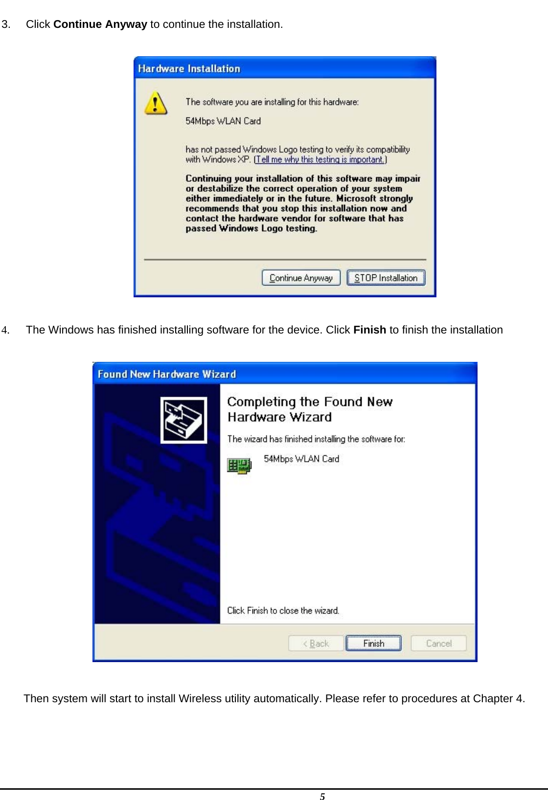
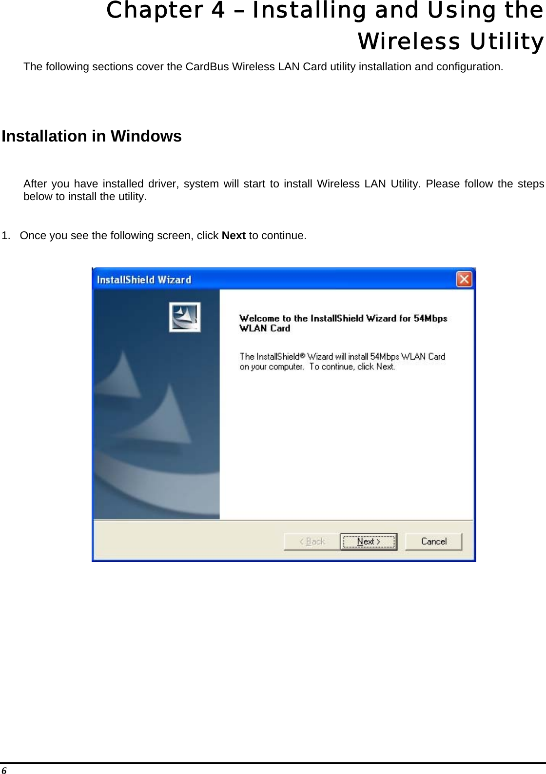
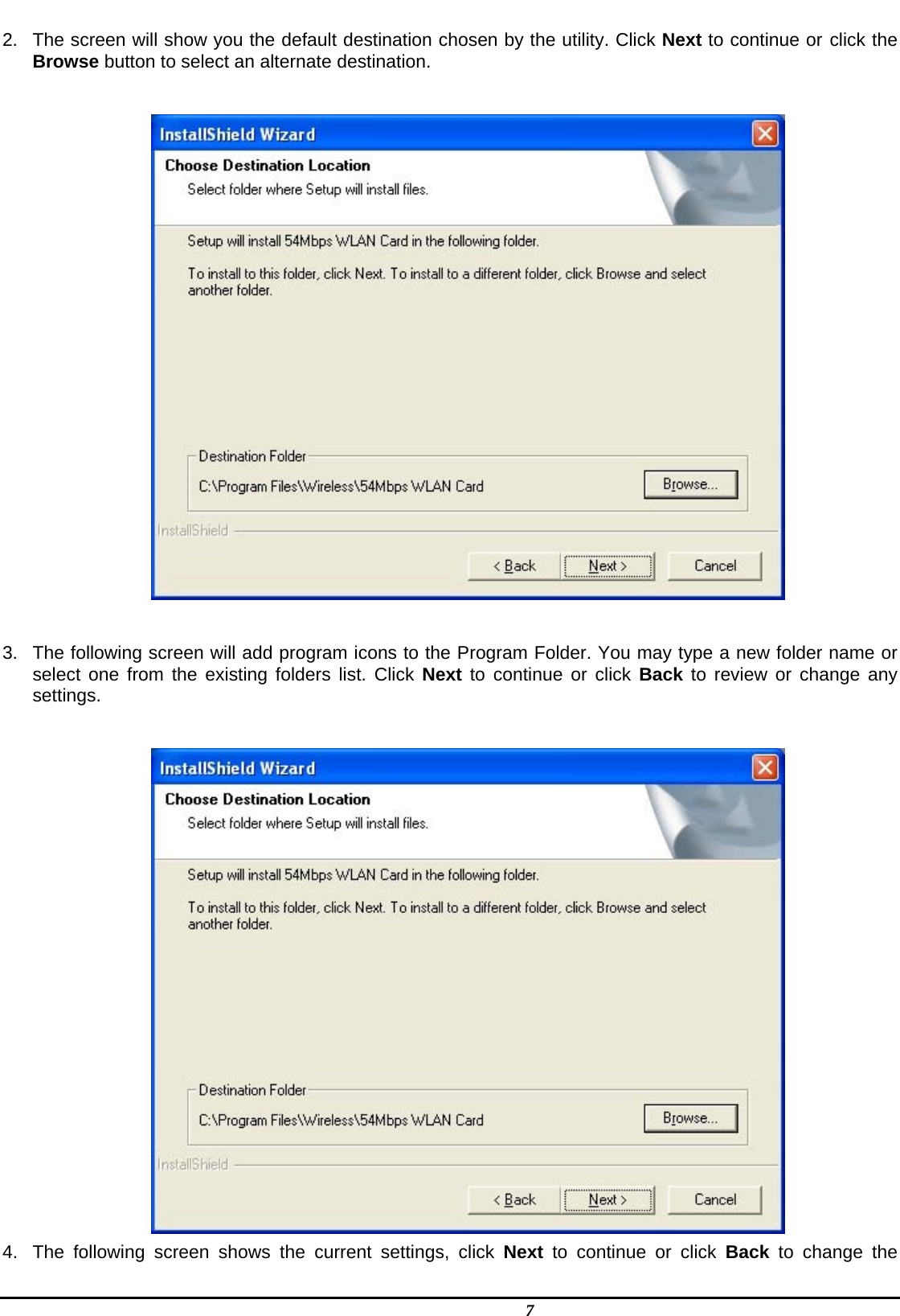
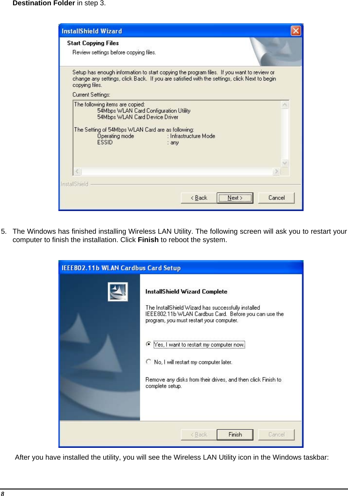
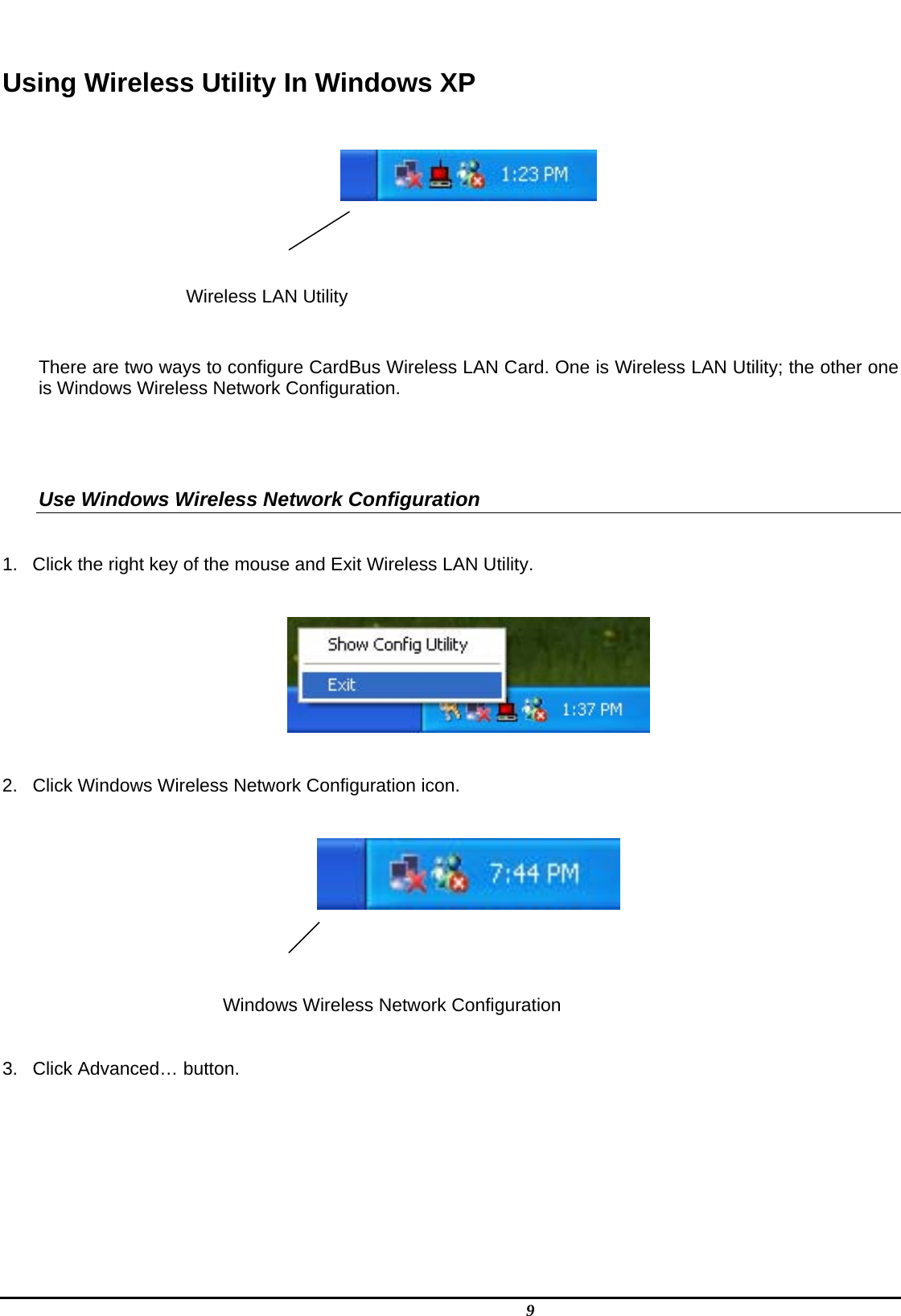
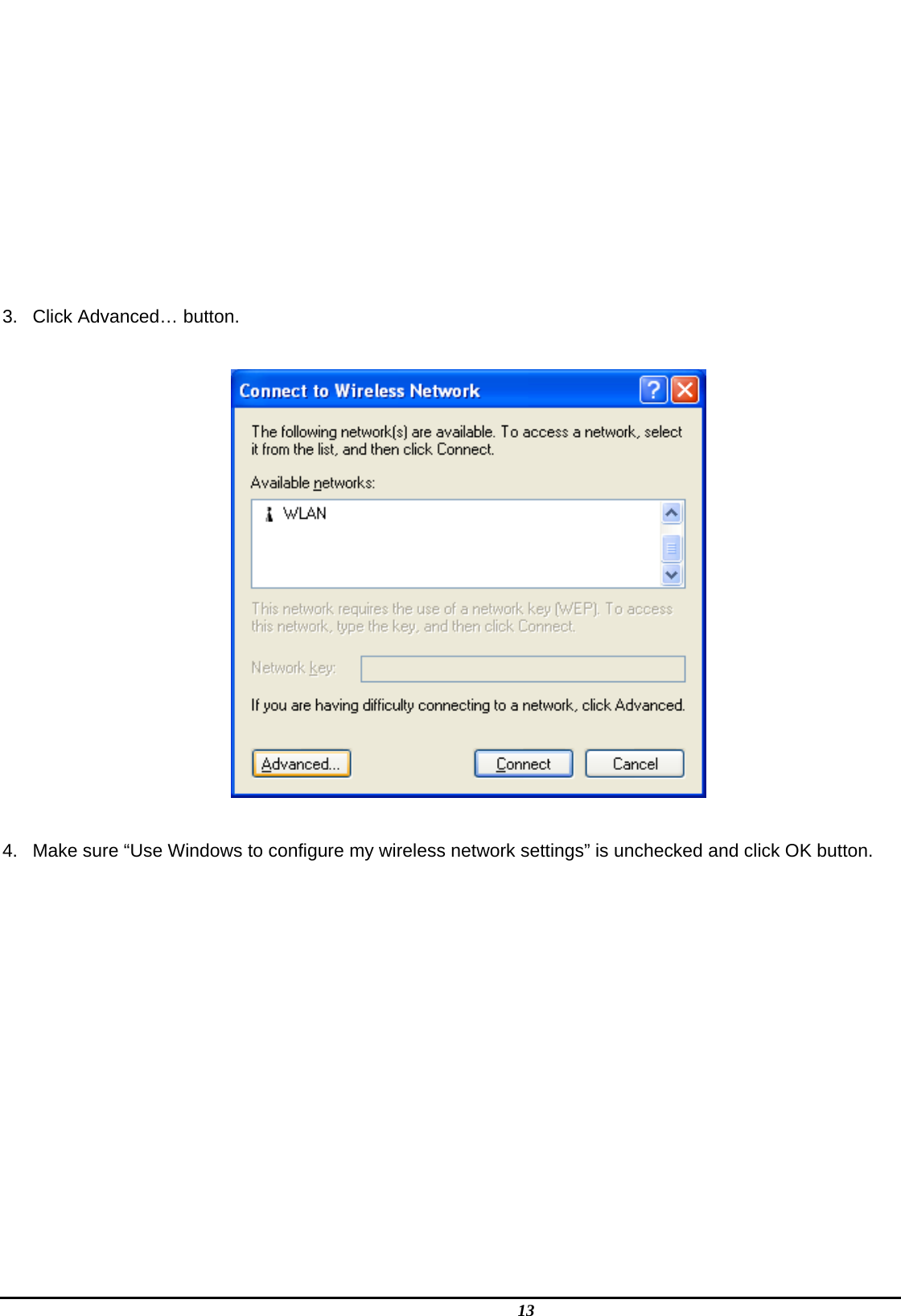
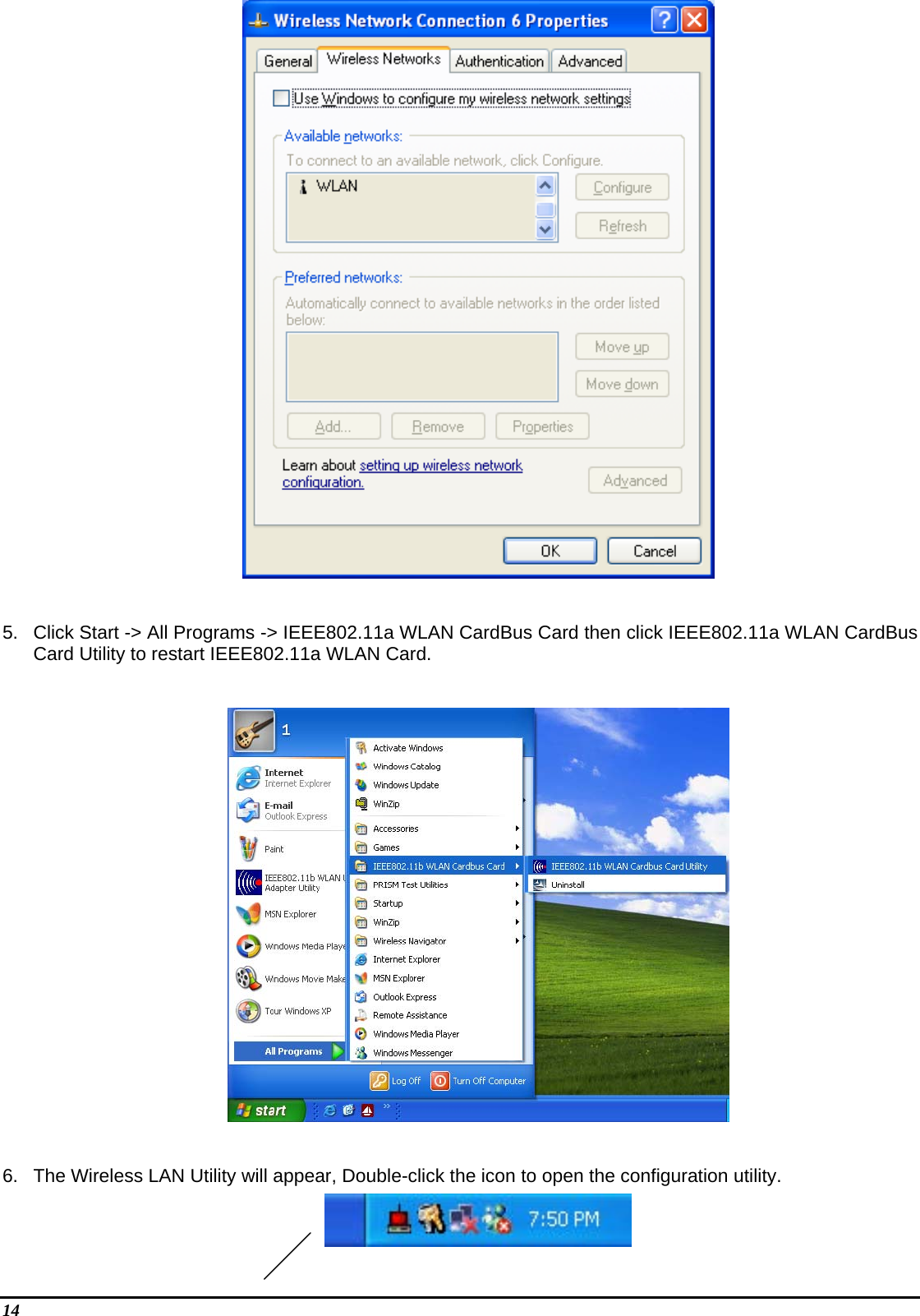
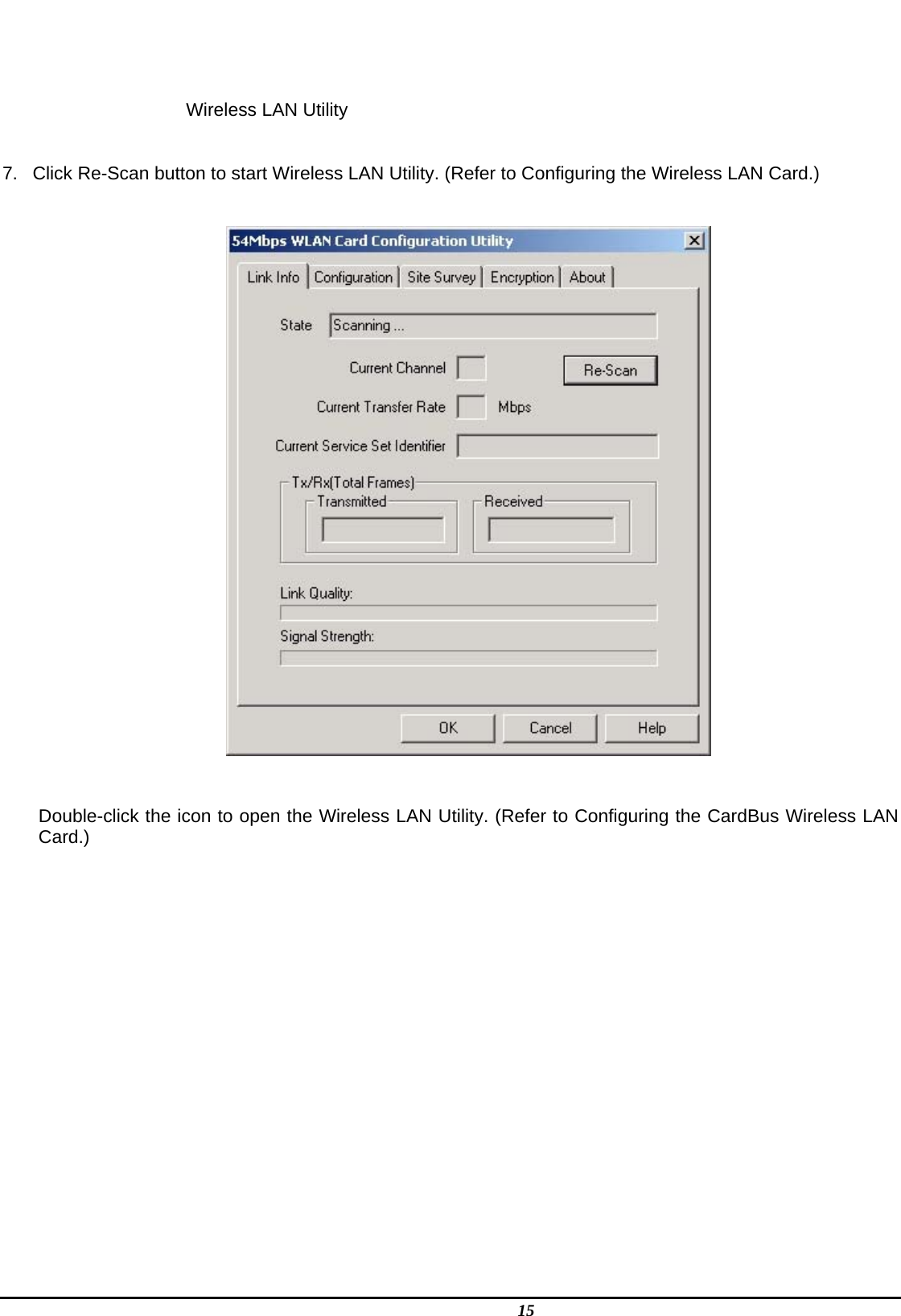
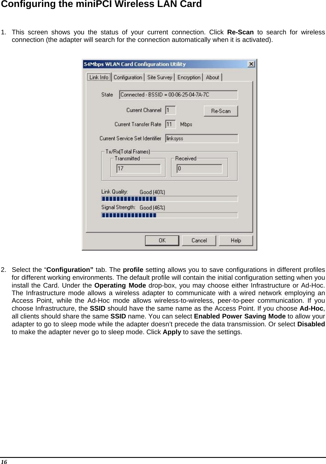
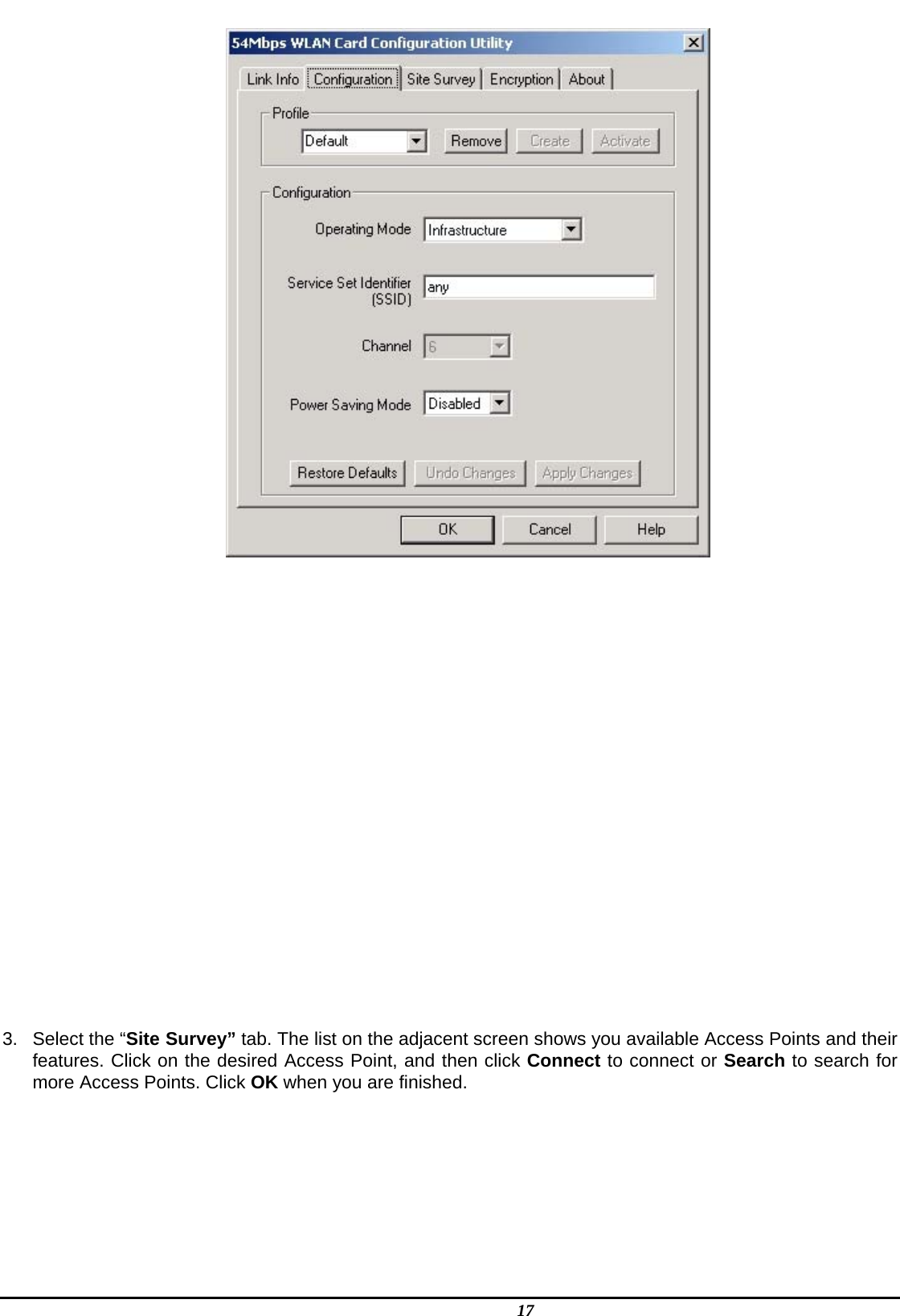
![4 Chapter 3 – Driver Installation for Windows The following sections cover miniPCI Wireless LAN Card driver installation in the Windows Operating Systems. Note! You have to install your hardware first before you begin to install the drivers. Driver installation for Windows XP Follow the steps below to install the MiniPCI Wireless LAN Card drivers for Windows XP. 1. Insert the miniPCI Wireless LAN Card . 2. After Windows XP detects the CardBus Wireless LAN Card, the Found New Hardware Wizard window appears. Select Install the software automatically [Recommended] and insert the driver CD-ROM into CD-ROM drive and click Next to continue.](https://usermanual.wiki/CyberTAN-Technology/WM820B/User-Guide-965670-Page-12.png)