Cyberdata Voip Intercom Users Manual
VoIP Intercom to the manual 8ebbbcaa-4add-4c89-8f74-8dd22062dbc2
2015-02-05
: Cyberdata Cyberdata-Voip-Intercom-Users-Manual-536695 cyberdata-voip-intercom-users-manual-536695 cyberdata pdf
Open the PDF directly: View PDF ![]() .
.
Page Count: 48
- Contents
- 1 Product Overview
- 2 Installing the VoIP Intercom
- 2.1 Parts List
- 2.2 Intercom Setup
- 2.3 Configure the Intercom Parameters
- 2.4 Upgrade the Firmware and Reboot the Intercom
- Appendix A: Mounting the Intercom
- Appendix B: Setting up a TFTP Server
- Appendix C: Troubleshooting/Technical Support
- Index
VoIP Intercom
Operations Guide
Part #010935
CyberData Corporation
2555 Garden Road
Monterey, CA 93940
(831) 373-2601
930181B

CyberData Corporation 930181B Operations Guide
PoE VoIP Intercom Operations Guide 930181B
Part # 010935
COPYRIGHT NOTICE:
© 2008, CyberData Corporation, ALL RIGHTS RESERVED.
This manual and related materials are the copyrighted property of CyberData Corporation. No part
of this manual or related materials may be reproduced or transmitted, in any form or by any means
(except for internal use by licensed customers), without prior express written permission of
CyberData Corporation. This manual, and the products, software, firmware, and/or hardware
described in this manual are the property of CyberData Corporation, provided under the terms of an
agreement between CyberData Corporation and recipient of this manual, and their use is subject to
that agreement and its terms.
DISCLAIMER: Except as expressly and specifically stated in a written agreement executed by
CyberData Corporation, CyberData Corporation makes no representation or warranty, express or
implied, including any warranty or merchantability or fitness for any purpose, with respect to this
manual or the products, software, firmware, and/or hardware described herein, and CyberData
Corporation assumes no liability for damages or claims resulting from any use of this manual or
such products, software, firmware, and/or hardware. CyberData Corporation reserves the right to
make changes, without notice, to this manual and to any such product, software, firmware, and/or
hardware.
OPEN SOURCE STATEMENT: Certain software components included in CyberData products are
subject to the GNU General Public License (GPL) and Lesser GNU General Public License (LGPL)
“open source” or “free software” licenses. Some of this Open Source Software may be owned by
third parties. Open Source Software is not subject to the terms and conditions of the CyberData
COPYRIGHT NOTICE or software licenses. Your right to copy, modify, and distribute any Open
Source Software is determined by the terms of the GPL, LGPL, or third party, according to who
licenses that software.
Software or firmware developed by CyberData that is unrelated to Open Source Software is
copyrighted by CyberData, subject to the terms of CyberData licenses, and may not be copied,
modified, reverse-engineered, or otherwise altered without explicit written permission from
CyberData Corporation.
TRADEMARK NOTICE: CyberData Corporation and the CyberData Corporation logos are
trademarks of CyberData Corporation. Other product names, trademarks, and service marks may be
the trademarks or registered trademarks of their respective owners.
Phone: (831) 373-2601
Technical Support Ext. 333
support@cyberdata.net
Fax: (831) 373-4193
Company and product information at www.cyberdata.net
CyberData Corporation 930181B Operations Guide
Important Safety Instructions
1. Read these instructions.
2. Keep these instructions.
3. Heed all warnings.
4. Follow all instructions.
5. Do not use this apparatus near water.
6. Clean only with dry cloth.
7. Do not block any ventilation openings. Install in accordance with the manufacturer’s
instructions.
8. Do not install near any heat sources such as radiators, heat registers, stoves, or other apparatus
(including apmplifiers) that produce heat.
9. Do not defeat the safety purpose of the polarized or grounding-type plug. A polarized plug has
two blades with one wider than the other. A grounding type plug has two blades and a third
grounding prong. The wide blade or the third prong are provided for your safety. If the
provided plug does not fit into your outlet, consult an electrician for replacement of the obsolete
outlet.
10. Protect the power cord from being walked on or pinched particularly at plugs, convenience
receptacles, and the point where they exit from the apparatus.
11. Only use attachments/accessories specified by the manufacturer.
12. Refer all servicing to qualified service personnel. Servicing is required when the apparatus has
been damaged in any way, such as power-supply cord or plug is damaged, liquid has been
spilled or objects have fallen into the apparatus, the apparatus has been exposed to rain or
moisture, does not operate normally, or has been dropped.
13. Prior to installation, consult local building and electrical code requirements.
14. WARNING: The VoIP Intercom enclosure is not rated for any AC voltages!
Warning
Electrical Hazard: This product should be installed by a licensed electrician
according to all local electrical and building codes.
Warning
Electrical Hazard: To prevent injury, this apparatus must be securely attached to
the floor/wall in accordance with the installation instructions.
GENERAL ALERT
GENERAL ALERT
CyberData Corporation 930181B Operations Guide
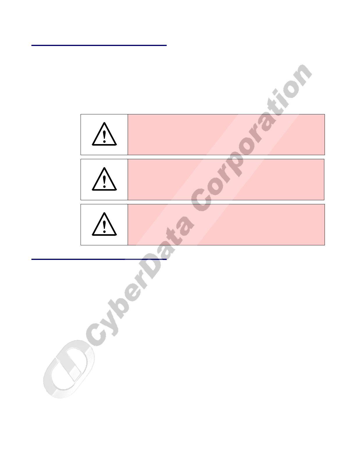
Pictorial Alert Icons
Hazard Levels
Danger: Indicates an imminently hazardous situation which, if not avoided, will result in death or
serious injury. This is limited to the most extreme situations.
Warning: Indicates a potentially hazardous situation which, if not avoided, could result in death or
serious injury.
Caution: Indicates a potentially hazardous situation which, if not avoided, could result in minor or
moderate injury. It may also alert users against unsafe practices.
Notice: Indicates a statement of company policy (that is, a safety policy or protection of property).
The safety guidelines for the equipment in this manual do not purport to address all the safety issues
of the equipment. It is the responsibility of the user to establish appropriate safety, ergonomic, and
health practices and determine the applicability of regulatory limitations prior to use. Potential
safety hazards are identified in this manual through the use of words Danger, Warning, and Caution,
the specific hazard type, and pictorial alert icons.
General Alert
This pictoral alert indicates a potentially hazardous situation. This alert will be
followed by a hazard level heading and more specific information about the
hazard.
Ground
This pictoral alert indicates the Earth grounding connection point.
GENERAL ALERT
CyberData Corporation 930181B Operations Guide
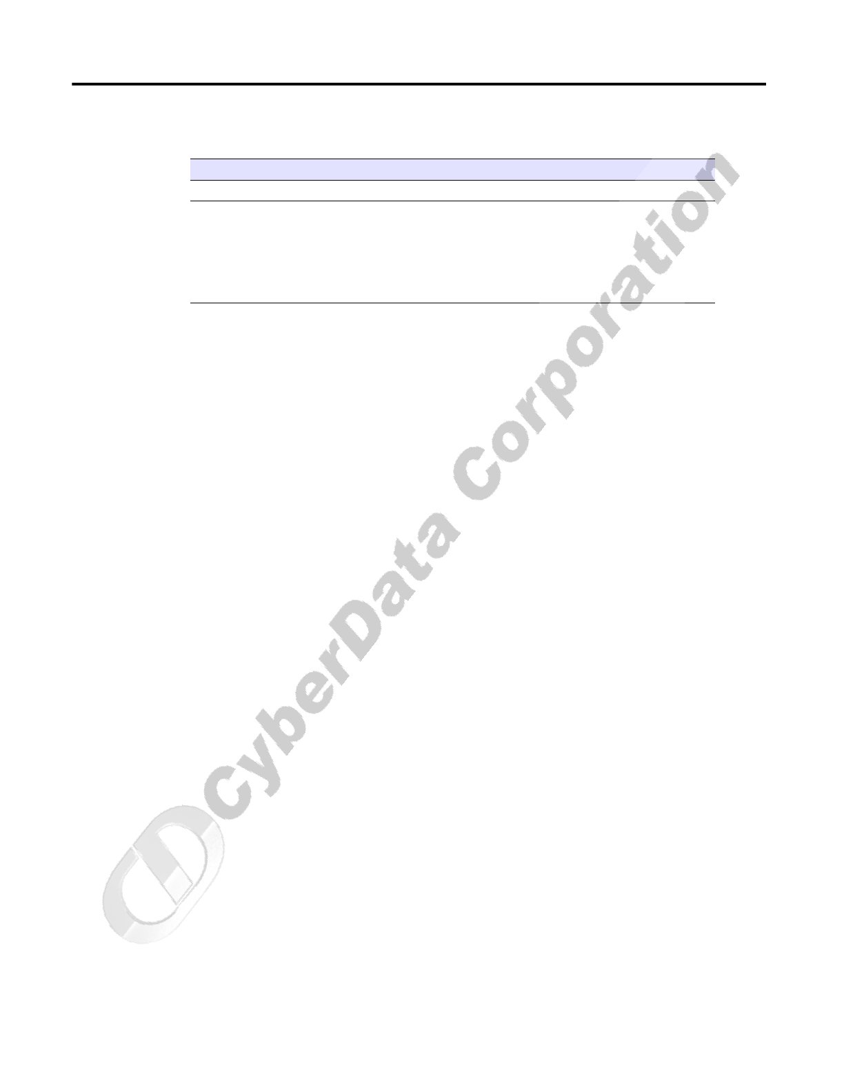
Revision History
Revision Date Released Description of Changes
A 12/11/2007 This is the first release of this manual.
B 4/25/2008 Adds information about the Auxiliary Relay in Section 2.3.3.1,
"Auxiliary Relay", Figure 2-16, and Ta b l e 2- 7 .
Adds Important Safety Instructions section.
Adds Figure 1-1, Figure 1-2, and Figure 1-3.
Updates the Solarwinds TFTP Server freeware URL.

CyberData Corporation 930181B Operations Guide

i
Operations Guide 930181B CyberData Corporation
Contents
Chapter 1 Product Overview 1
1.1 Typical System Installation ...................................................................................................................1
1.2 Product Features .....................................................................................................................................3
1.3 Supported Protocols ..............................................................................................................................3
1.4 Supported SIP Servers ...........................................................................................................................4
1.5 Product Specifications ...........................................................................................................................4
Chapter 2 Installing the VoIP Intercom 5
2.1 Parts List ..................................................................................................................................................5
2.2 Intercom Setup ........................................................................................................................................6
2.2.1 VoIP Intercom Connections .......................................................................................................6
2.2.2 Connecting a Device to the Relay .............................................................................................7
2.2.3 Identifying the VoIP Intercom Connectors ..............................................................................7
2.2.4 Call Button and Indicator Light ..............................................................................................10
2.2.5 Network Connectivity, and Data Rate .................................................................................. 11
2.2.6 RTFM Switch Jumper ...............................................................................................................13
2.2.7 Adjust the Volume ....................................................................................................................15
2.3 Configure the Intercom Parameters .................................................................................................16
2.3.1 Log in to the Configuration Home Page ................................................................................16
2.3.2 Configure the Network Parameters ......................................................................................18
2.3.3 Set up the Intercom ...................................................................................................................20
2.3.4 Configure the SIP Parameters .................................................................................................22
2.4 Upgrade the Firmware and Reboot the Intercom ...........................................................................24
2.4.1 Reboot the Intercom ..................................................................................................................25
Appendix A Mounting the Intercom 27
A.1 Mount the Intercom ...........................................................................................................................27
Appendix B Setting up a TFTP Server 33
B.1 Set up a TFTP Server ...........................................................................................................................33
B.1.1 In a LINUX Environment ........................................................................................................33
B.1.2 In a Windows Environment ...................................................................................................33
B.1.3 In a Solarwinds Server Environment ....................................................................................33
Appendix C Troubleshooting/Technical Support 35
C.1 Frequently Asked Questions (FAQ) .................................................................................................35
C.2 Documentation ....................................................................................................................................35
C.3 Contact Information ............................................................................................................................35
C.4 Warranty ...............................................................................................................................................36
Index 37

CyberData Corporation 930181B Operations Guide
ii
1
Operations Guide 930181B CyberData Corporation
1 Product Overview
The Voice-over-IP (VoIP) Intercom is a SIP endpoint designed to provide VoIP phone connectivity in
a tamper proof and secure package.
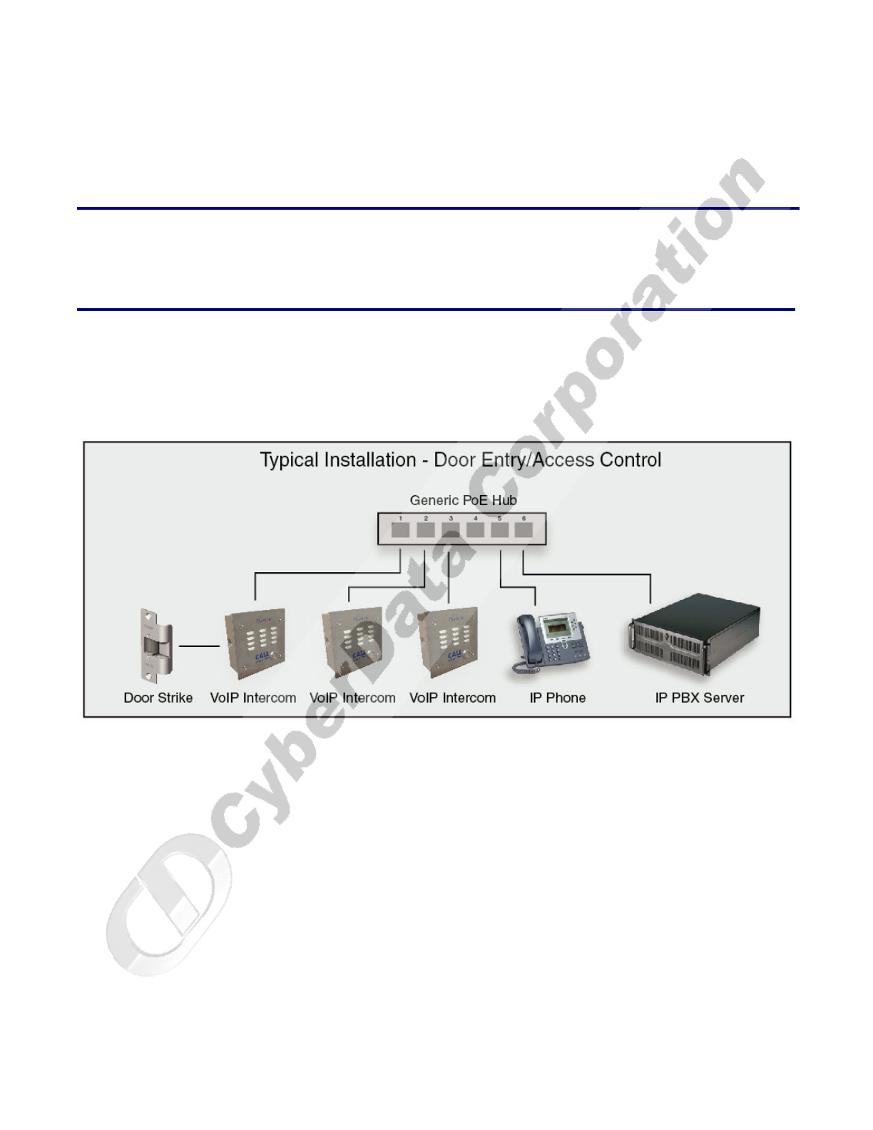
1.1 Typical System Installation
Figure 1-1, Figure 1-2, and Figure 1-3 illustrate how the VoIP Intercoms can be installed as part of a
VoIP phone system.
Figure 1-1. Typical Installation—Door Entry/Access Control
CyberData Corporation 930181B Operations Guide
Product Overview
Typical System Installation
2
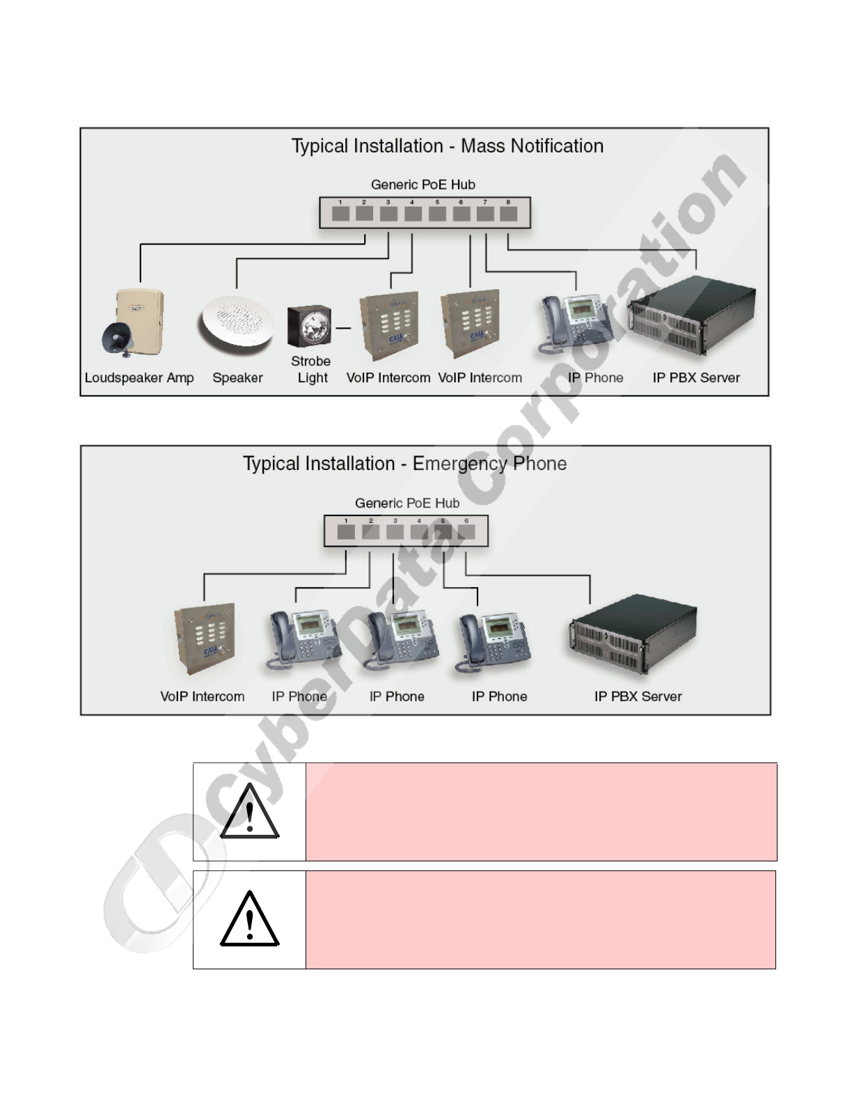
Figure 1-2. Typical Installation—Mass Notification
Figure 1-3. Typical Installation—Emergency Phone
.
Warning
Electrical Hazard: The VoIP Intercom enclosure is not rated for any AC voltages.
Warning
Electrical Hazard: This product should be installed by a licensed electrician
according to all local electrical and building codes.
GENERAL ALERT
GENERAL ALERT
Product Overview
Product Features
Operations Guide 930181B CyberData Corporation
3
1.2 Product Features
1.3 Supported Protocols
The Intercom supports:
●SIP
●HTTP Web-based configuration
Provides an intuitive user interface for easy system configuration and verification of Intercom
operations.
●DHCP Client
Dynamically assigns IP addresses in addition to the option to use static addressing.
●TFTP Client
Facilitates Web-based firmware upgrades of the latest Intercom capabilities.
Warning
Electrical Hazard: To prevent injury, this apparatus must be securely attached to
the floor/wall in accordance with the installation instructions.
GENERAL ALERT
●
SIP
●
Dual speeds of 10 Mbps and 100 Mbps
●
802.3af compliant
●
2 gang outlet box size
●
Full duplex voice operation
●
Network/Web management
●
Network adjustable speaker volume
adjustment
●
Network configurable microphone input
sensitivity adjustment
●
Network Downloadable product firmware
●
Doubles as a paging speaker
●
Call button
●
Call activity indicator (light)
●
Tamper proof design
●
1 dry contact relay for auxiliary control
●
3 year Warranty
VoIP Intercom
Backdoor
Backdoor
Backdoor
Backdoor
CyberData Corporation 930181B Operations Guide
Product Overview
Supported SIP Servers
4
●RTP
●RTP/AVP - Audio Video Profile
●Audio Encodings
PCMU (G.711 mu-law)
PCMA (G.711 A-law)
Packet Time 20 ms
1.4 Supported SIP Servers
The following link contains information on how to configure the Intercom for the supported SIP
servers:
http://www.cyberdata.net/support/voip/intercom.html
1.5 Product Specifications
Category Specification
Speaker Output 8 Watts Peak Power
Network Rate 10/100 Mbps
Power Requirement 802.3af compliant or 5V at 1000 mA
Protocol SIP
Part Number 010935
Dimensions 5” x 5” x 2.5”
Weight
Auxiliary Relay
1.6 lbs./shipping weight of 2.2 lbs.
(0.7 kg/shipping weight of 1.0kg)
2 A at 30 VDC
CyberData Corporation 930181B Operations Guide
Installing the VoIP Intercom
Intercom Setup
6
2.2 Intercom Setup
2.2.1 VoIP Intercom Connections
Figure 2-4 shows the pin connections on the J7 (terminal block). This terminal block can accept a
wire range from 16 AWG to 26 AWG.
Note As an alternative to using PoE power, you can supply 5 VDC at 1000 mA into the terminal
block.
Figure 2-4. VoIP Intercom Connections
1234
Alternate Power Input:
1 = +5V at 1000 mA
2 = Power Ground
Relay Contact:
(1A at 30 VDC for continuous loads)
3 = Normally Open Common
4 = Normally Open Contact
J7 - Terminal Block
-
-
WIRE IN,
Accept Wire Range
From 16-26 AWG
34
Installing the VoIP Intercom
Intercom Setup
Operations Guide 930181B CyberData Corporation
7
2.2.2 Connecting a Device to the Relay
A normally open relay is provided to enable users to switch on an auxiliary device like a door
buzzer (see Figure 2-4). The relay contacts are limited to 1 amp at 30VDC. The relay on time is
selectable through the web interface and is controlled by DTMF tones generated from the phone
being called. The DTMF tones are selectable from the web interface as well. See Section 2.3.3, "Set up
the Intercom".
.
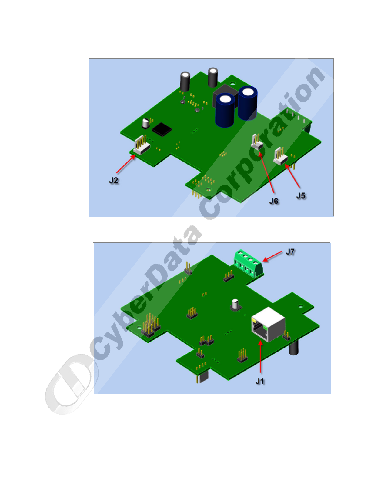
2.2.3 Identifying the VoIP Intercom Connectors
See Figure 2-5, Figure 2-6, and Table 2-2 to identify the connectors and functions.
Warning
Electrical Hazard: The VoIP Intercom enclosure is not rated for any AC voltages.
Warning
Electrical Hazard: This product should be installed by a licensed electrician
according to all local electrical and building codes.
Warning
Electrical Hazard: To prevent injury, this apparatus must be securely attached to
the floor/wall in accordance with the installation instructions.
GENERAL ALERT
GENERAL ALERT
GENERAL ALERT
CyberData Corporation 930181B Operations Guide
Installing the VoIP Intercom
Intercom Setup
8
Figure 2-5. J2, J5, and J6 Connector Locations
Figure 2-6. J1 and J7 Connector Locations
Installing the VoIP Intercom
Intercom Setup
Operations Guide 930181B CyberData Corporation
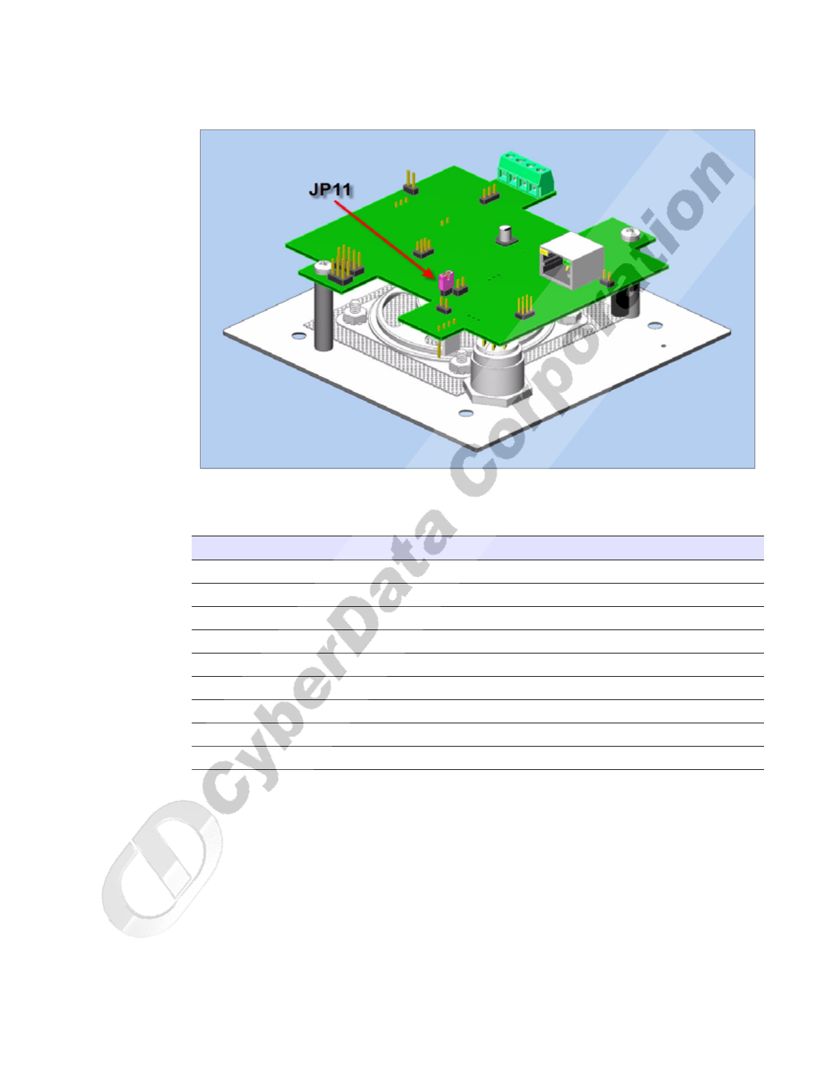
9
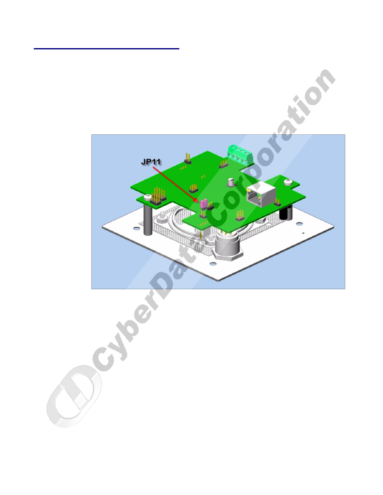
Figure 2-7. JP11—RTFM Switch Jumper
See Table 2-2 for the connector settings.
Table 2-2. Connector Settings
Jumper Setting
J1 Network Connection
J4 J-Tag (Factory only)
J7 Terminal Block (see the diagram above, Figure ??)
JP2 Call-Button/LED interface
JP4 Reset (Factory only)
JP5 Microphone Interface
JP6 Speaker Interface
JP8 Console (Factory only)
JP11 RTFM (describe in text)
CyberData Corporation 930181B Operations Guide
Installing the VoIP Intercom
Intercom Setup
10
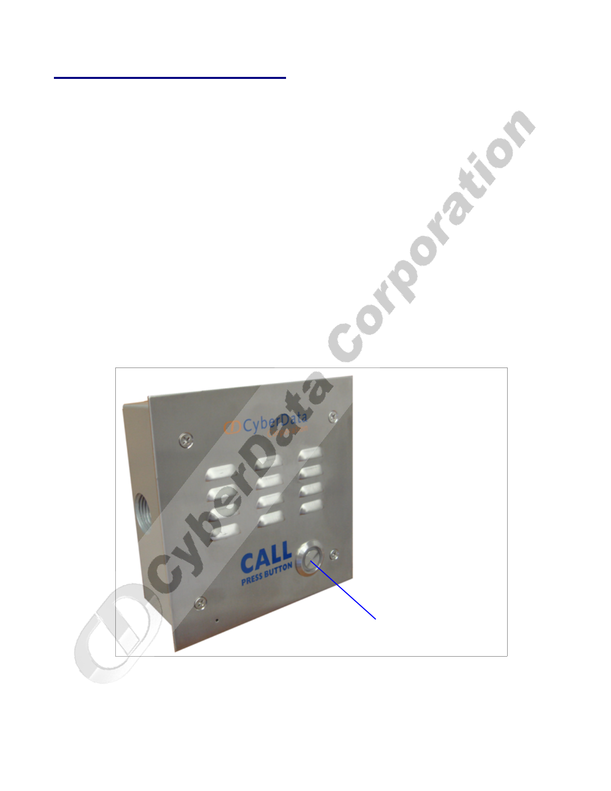
2.2.4 Call Button and Indicator Light
2.2.4.1 Initial Power
Upon initial power or reset, you will see the following:
• The light is on.
• The light will blink twice to indicate that the intercom has acquired its network settings and
is operational.
• The first blink indicates that the intercom has acquired its network settings.
• The second blink indicates that the intercom is operational.
2.2.4.2 Calling
●You may initiate a call by pressing the Call button.
●An active call is indicated by the light blinking at one second intervals.
●The intercom will automatically answer an incoming call.
●You can press the Call button to terminate an active call whether the call was an incoming call
or a call that was initiated by you.
Figure 2-8. Call Button and Indicator Light
Call button and indicator light
Installing the VoIP Intercom
Intercom Setup
Operations Guide 930181B CyberData Corporation
11
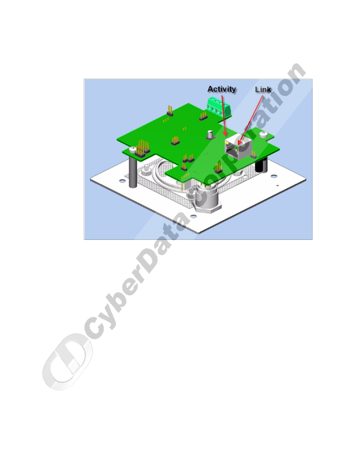
2.2.5 Network Connectivity, and Data Rate
When you plug in the Ethernet cable or power supply:
●The square, green Link light above the Ethernet port indicates that the network connection has
been established (see Figure 2-9 and Figure 2-10). The Link light changes color to confirm the
auto-negotiated baud rate:
• This light is yellow at 10 Mbps.
• It is orange at 100 Mbps.
Figure 2-9. Network Connector Prior to Installation
Link
Activity
Ethernet
CyberData Corporation 930181B Operations Guide
Installing the VoIP Intercom
Intercom Setup
12
2.2.5.1 Verify Network Activity
The square, yellow Activity light blinks when there is network activity.
Figure 2-10. Network Connector
Installing the VoIP Intercom
Intercom Setup
Operations Guide 930181B CyberData Corporation
13
2.2.6 RTFM Switch Jumper
When the Intercom is operational and linked to the network, use the Reset Test Function
Management (RTFM) switch (see Figure 2-11) on the Intercom board to announce and confirm the
Intercom’s IP Address, test that the audio is working, and check the volume.
Note You must do this test prior to final assembly. Please remember to remove the RTFM switch
jumper prior to final assembly.
Figure 2-11. RTFM Switch Jumper
2.2.6.1 Announcing the IP Address
To announce an Intercom’s current IP address:
1. Unplug the intercom.
2. Install the RTFM jumper.
3. Plug the network cable into the intercom to supply power to the intercom. The LED will
illuminate during initialization, blink once, and then turn off.
4. The intercom will announce the IP address.
Note If you installed the RTFM jumper, and if you press the Call button for 10 seconds, the
default factory settings will be restored.

CyberData Corporation 930181B Operations Guide
Installing the VoIP Intercom
Intercom Setup
14
2.2.6.2 Restoring the Factory Default Settings
To restore the factory default settings:
1. Complete the steps in Section 2.2.6.1, "Announcing the IP Address".
2. Press and hold the Call button for 10 seconds.
3. When you hear the announcement, release the Call button. The factory default settings are
restored, and the intercom will automatically restart.
2.2.6.3 Restore the Factory Default Settings
When troubleshooting configuration problems, it is sometimes convenient to restore the device to a
known state.
Each Intercom is delivered with factory set default values for the parameters indicated in Table 2-3.
Use the RTFM switch on the Intercom face to restore these parameters to the factory default settings.
Note When you use the RTFM switch, the factory default settings are restored for only the
parameters indicated in Table 2-3. The other parameters in the current Intercom
configuration will remain unchanged.
To restore these parameters to the factory default settings:
Table 2-3. Factory Default Settings
Parameter Factory Default Setting
IP Addressing static
IP Address 192.168.3.10
Web Access Username admin
Web Access Password admin
Subnet Mask 255.255.255.0
Installing the VoIP Intercom
Intercom Setup
Operations Guide 930181B CyberData Corporation
15
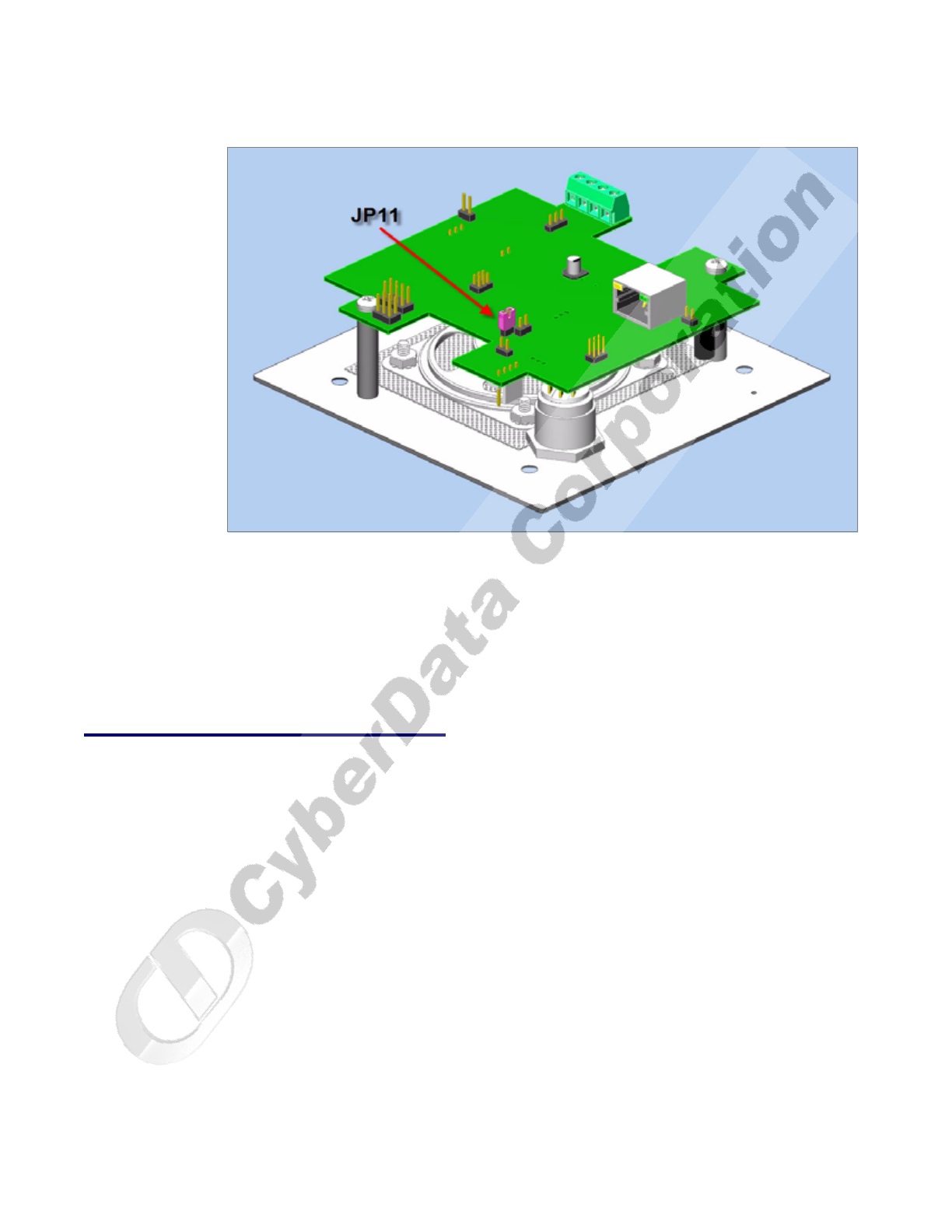
Figure 2-12. RTFM Switch Jumper
To announce an Intercom’s current IP address:
1. Install the RTFM jumper.
2. After two seconds, the IP address will be announced.
Note If you installed the RTFM jumper, and if you press the call button for 10 seconds, the default
factory settings will be initiated.
2.2.7 Adjust the Volume
You will be only able to adjust the volume through the network configuration page.
CyberData Corporation 930181B Operations Guide
Installing the VoIP Intercom
Configure the Intercom Parameters
16
2.3 Configure the Intercom Parameters
To configure the Intercom online, use a standard web browser.
Configure each Intercom and verify its operation before you mount it. When you are ready to mount
an Intercom, refer to Chapter A, “Mounting the Intercom” for instructions.
All Intercoms are initially configured with the following default IP settings:
When configuring more than one Intercom, attach the Intercoms to the network and configure one
at a time to avoid IP address conflicts.
2.3.1 Log in to the Configuration Home Page
1. Open your browser to the Intercom IP address.
For the initial configuration of the Intercom, open your browser to the default IP address:
http://192.168.3.10
Note Make sure that the PC is on the same IP network as the Intercom.
2. When prompted, use the following default Web Access Username and Web Access Password
to access the Home Page (Figure 2-13):
Web Access Username: admin
Web Access Password: admin
Table 2-4. Factory Default Settings
Parameter Factory Default Setting
IP Addressing static
IP Address 192.168.3.10
Web Access Username admin
Web Access Password admin
Subnet Mask 255.255.255.0
Default Gateway 192.168.3.1
Installing the VoIP Intercom
Configure the Intercom Parameters
Operations Guide 930181B CyberData Corporation
17
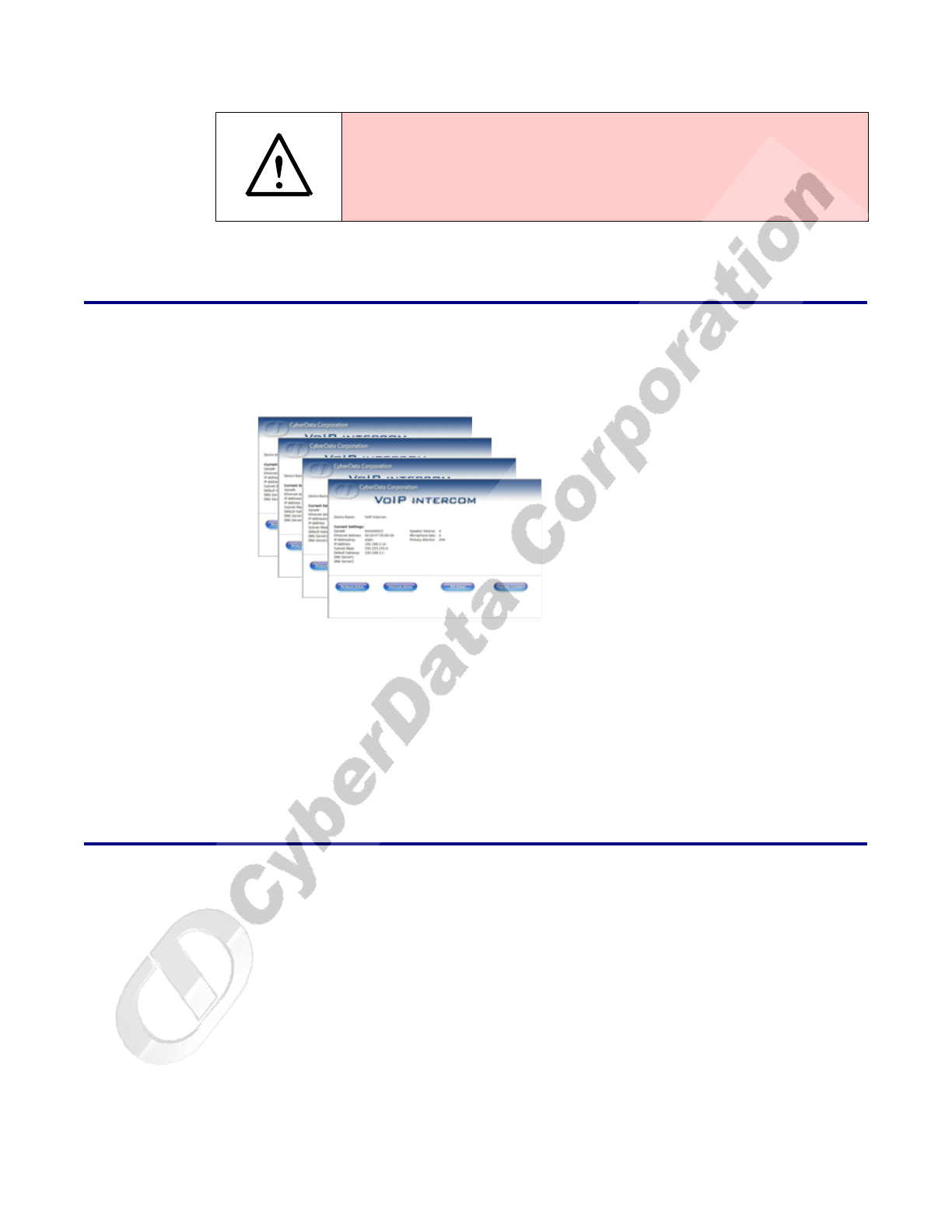
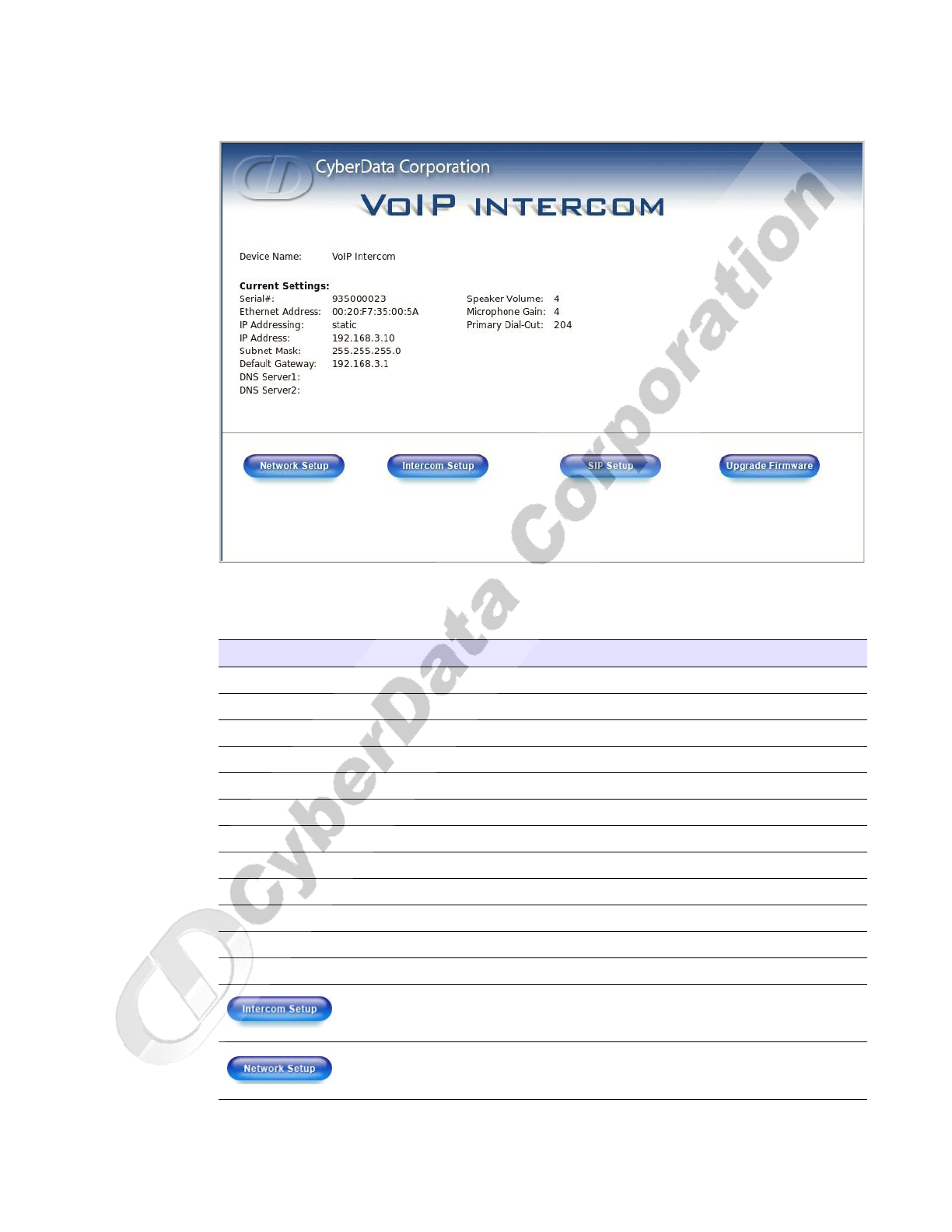
Figure 2-13. Home Page
3. On the Home Page, review the setup details and navigation buttons described in Table 2-5.
Table 2-5. Home Page Overview
Web Page Item Description
Device Name Shows the device name.
Serial # Device serial number.
Ethernet Address Device ethernet address.
IP Addressing Shows the current IP addressing setting (DHCP or static).
IP Address Shows the current IP address.
Subnet Mask Shows the current subnet mask address.
Default Gateway Shows the current default gateway address.
DNS Server 1 Shows the current DNS server 1address.
DNS Server 2 Shows the current DNS server 2address.
Speaker Volume (0-9) Shows the current volume level.
Microphone Gain (0-9) Shows the current microphone gain level.
Primary Dial-Out Shows the current primary dial-out number
Link to the Intercom Setup web page.
Link to the Network Setup web page.
CyberData Corporation 930181B Operations Guide
Installing the VoIP Intercom
Configure the Intercom Parameters
18
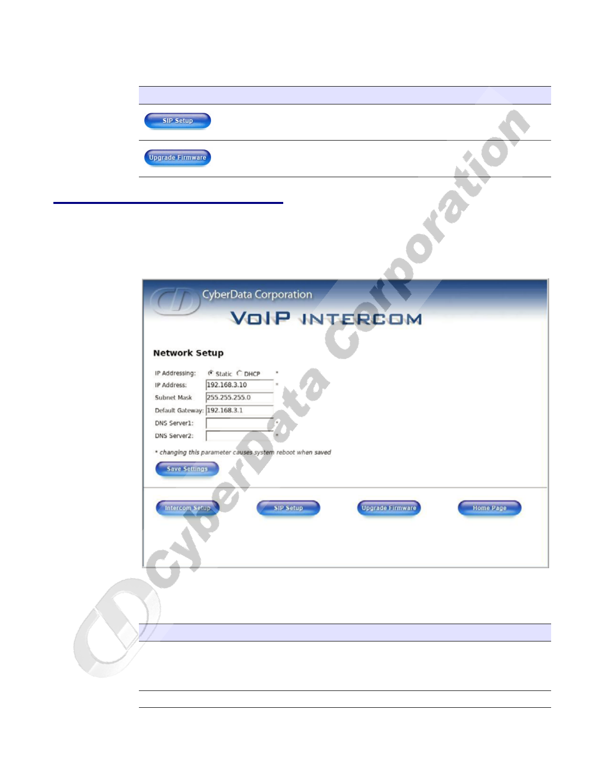
2.3.2 Configure the Network Parameters
1. Click the Network Setup button to open the Network Setup page (Figure 2-14).
Figure 2-14. Network Setup Page
2. On the Network Setup page, enter values for the parameters indicated in Table 2-6.
Link to the SIP Setup web page.
Link to the Upgrade Firmware web page.
Table 2-5. Home Page Overview (continued)
Web Page Item Description
Table 2-6. Network Setup Parameters
Web Page Item Description
IP Addressing* Select either DHCP IP Addressing or Static IP Addressing by
marking the appropriate radio button. If you select Static, configure
the remaining parameters indicated in Table 2-6. If you select DHCP,
go to Step 3.
IP Address* Enter the Static IP address.
Installing the VoIP Intercom
Configure the Intercom Parameters
Operations Guide 930181B CyberData Corporation
19
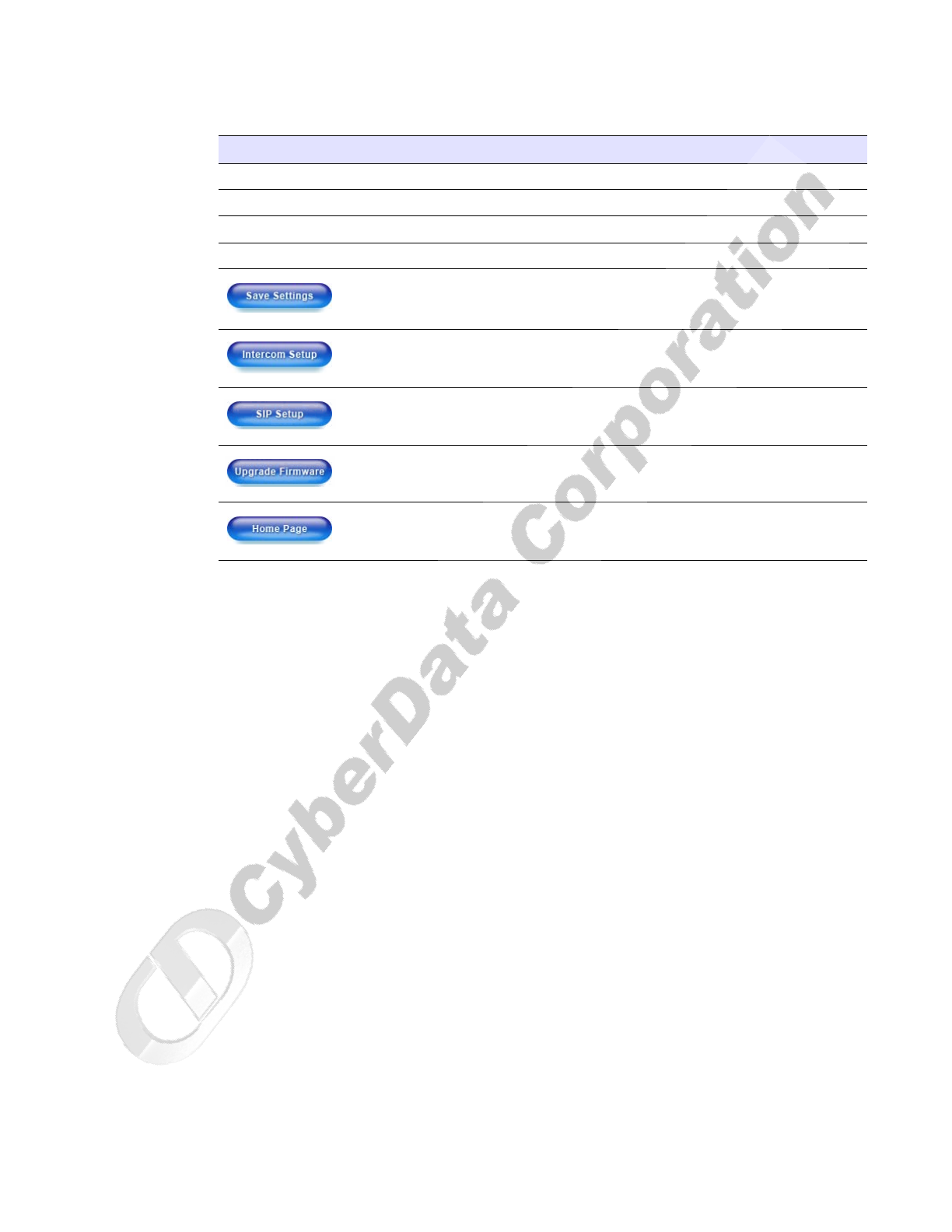
3. After changing the parameters, click Save Settings. This updates the changed parameters and
reboots the Intercom if appropriate.
4. Connect the Intercom to the target network.
5. From a system on the same network as the Intercom, open a browser with the new IP address of
the Intercom.
Subnet Mask Enter the Subnet Mask address.
Default Gateway Enter the Default Gateway address.
DNS Server 1* Enter the DNS Server 1 address.
DNS Server 2* Enter the DNS Server 2 address.
Click this button to save your configuration settings. Changing a
parameter that has an asterisk next to it will cause a system reboot
when saved.
Link to the Intercom Setup page.
Link to the SIP Setup page.
Link to the Upgrade Firmware page.
Link to the Home page.
Table 2-6. Network Setup Parameters (continued)
Web Page Item Description
CyberData Corporation 930181B Operations Guide
Installing the VoIP Intercom
Configure the Intercom Parameters
20
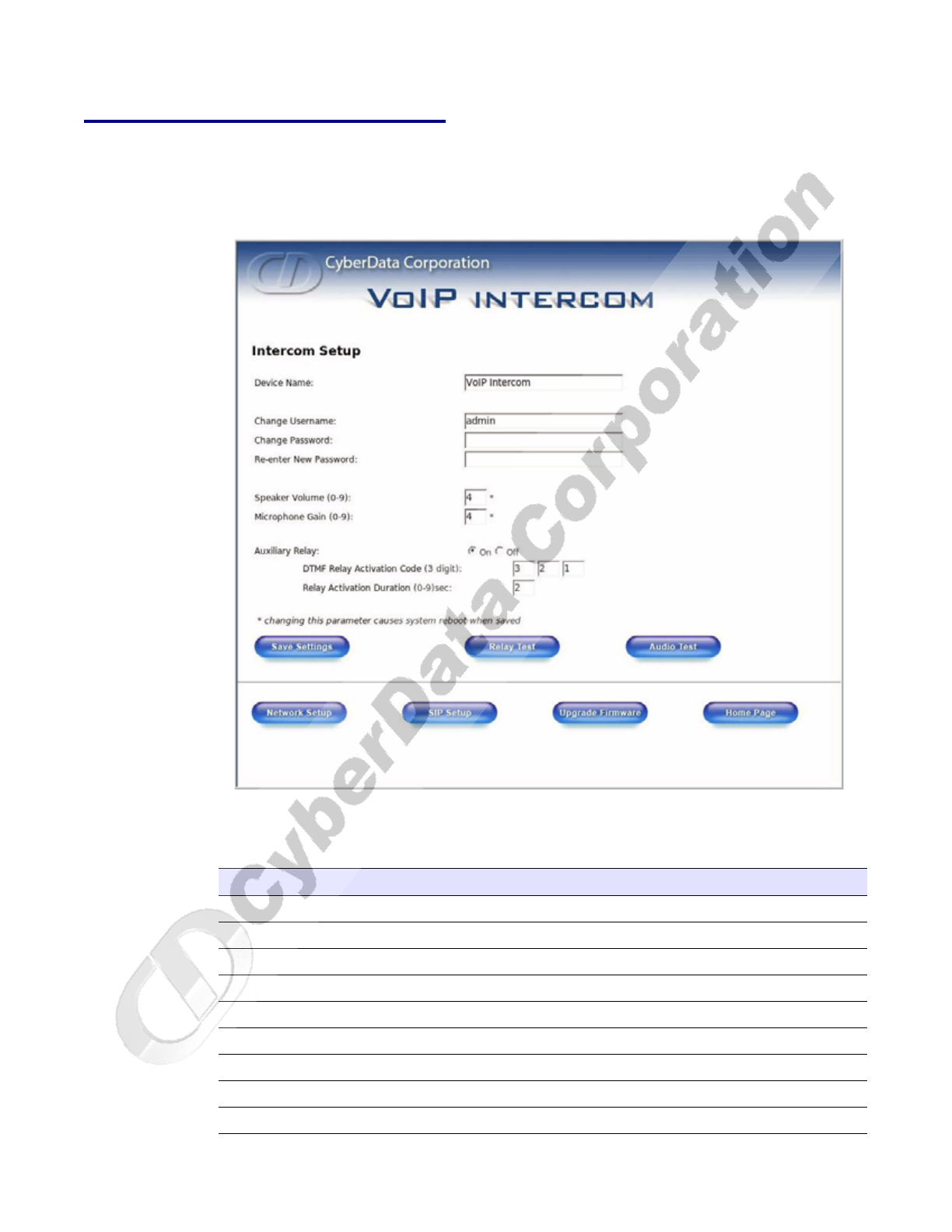
2.3.3 Set up the Intercom
1. Click the Intercom Setup button to open the Intercom Setup page. See Figure 2-15.
Figure 2-15. Intercom Setup
2. On the Intercom Setup page, enter values for the parameters indicated in Table 2-7.
Table 2-7. Intercom Setup Parameters
Web Page Item Description
Device Name Enter a descriptive name for this device (if desired).
Change Username Use this field to change the Web Access Username
Change Password Use this field to change the Web Access Password
Re-enter New Password Use this field to re-enter a new password
Speaker Volume (0 - 9) Shows the current volume level.
Microphone Gain (0 - 9) Shows the current microphone gain level.
Auxiliary Relay Allows you to enable or disable the auxiliary relay.
DTMF Relay Activation Code (3 digits) Use this field to enter the DTMF relay activation code.
Relay Activation Duration (0 - 9 seconds) Use this field to enter the relay activation duration.
Installing the VoIP Intercom
Configure the Intercom Parameters
Operations Guide 930181B CyberData Corporation
21
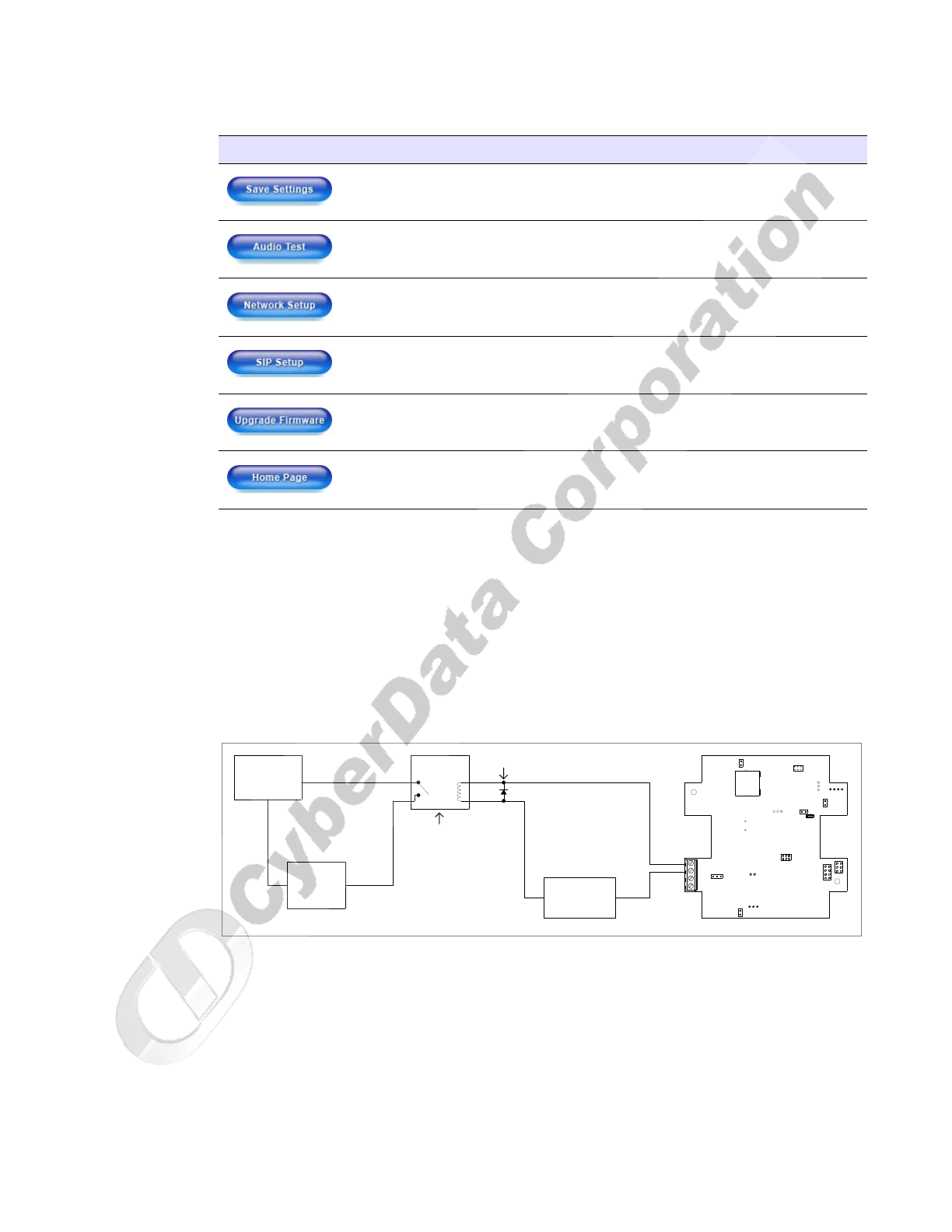
3. After changing the parameters, click Save Settings.
2.3.3.1 Auxiliary Relay
The CyberData VoIP Intercom provides an auxiliary relay that allows you to control an auxiliary
device co-located with the Intercom via DTMF tones sent from the default dial-out extension.
Note The three digit code for the auxiliary relay must be sent in conformance with RFC2833
DTMF generation.
Figure 2-16. Auxiliary Relay Wiring Diagram
Click on this button to save your configuration settings.
Click on this button to do an audio test. Generates a voice
message for testing the Intercom audio quality and volume.
Link to the Network Setup page.
Link to the SIP Setup page.
Link to the Upgrade Firmware page.
Link to the Home page.
Table 2-7. Intercom Setup Parameters (continued)
Web Page Item Description
1
2
3
4
+
-
DC
POWER SUPPLY
30 VDC @ 1A
MAX.
IN
Switching Diode
High PIV UltraFast
Solid State
or
Mechanical
Relay
Controlled Device
Depending Upon
AC or DC rated
Output Contacts
Requirements
Power Source
AC or DC
Controlled Device
Such As
Electric Door Strike
or
Strobe Light
VoIP Intercom
()
OUT
CyberData Corporation 930181B Operations Guide
Installing the VoIP Intercom
Configure the Intercom Parameters
22
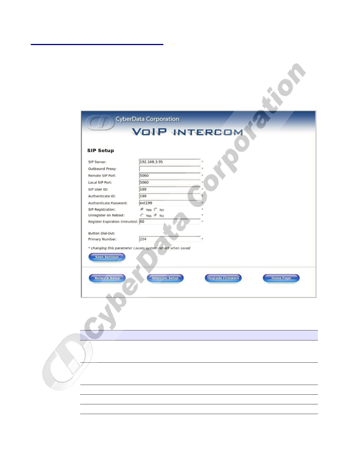
2.3.4 Configure the SIP Parameters
1. Click SIP Setup to open the SIP Setup page (Figure 2-17).
Note For specific server configurations, go to the following URL:
http://www.cyberdata.net/support/voip/intercom.html
Figure 2-17. SIP Setup Page
2. On the SIP Setup page, enter values for the parameters indicated in Table 2-8.
Table 2-8. SIP Setup Parameters
Web Page Item Description
SIP Server* Enter the SIP server represented as either a numeric IP
address in dotted decimal notation or the fully qualified
host name (FQHN) up to 64 characters.
Outbound Proxy Enter the Outbound Proxy as either a numeric IP address
in dotted decimal notation or the fully qualified host name
(FQHN) up to 64 characters.
Remote SIP Port* Enter the Remote SIP Port number (default 5060).
Local SIP Port* Enter the Local SIP Port number (default 5060).
SIP User ID* Enter the SIP User ID (up to 25 alphanumeric characters).
Installing the VoIP Intercom
Configure the Intercom Parameters
Operations Guide 930181B CyberData Corporation
23
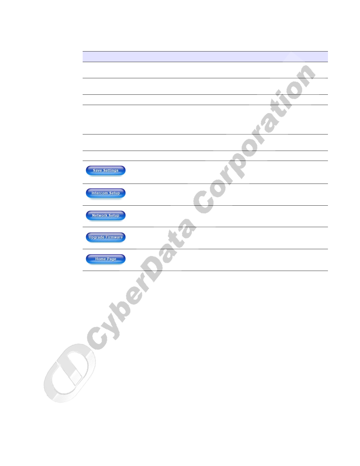
3. After changing the parameters, click Save Settings.
Authenticate ID* Enter the Authenticate ID (up to 25 alphanumeric
characters).
Authenticate Password* Enter the Authenticate Password (up to 25 alphanumeric
characters).
SIP Registration* Enable/Disable SIP Registration.
Unregister on Reboot* • Select Yes to automatically unregister the Intercom when
it is rebooted.
•Select No to keep the Intercom registered when it is
rebooted.
Register Expiration* Enter the SIP Registration lease time in minutes (default 60
minutes).
Button Dial-Out: Primary Number Enter the button dial-out primary number.
Click this button to save your configuration settings.
Changing a parameter that has an asterisk next to it will
cause a system reboot when saved.
Link to the Intercom Setup page.
Link to the Network Setup page.
Link to the Upgrade Firmware page.
Link to the Home page.
Table 2-8. SIP Setup Parameters (continued)
Web Page Item Description
CyberData Corporation 930181B Operations Guide
Installing the VoIP Intercom
Upgrade the Firmware and Reboot the Intercom
24
2.4 Upgrade the Firmware and Reboot the Intercom
To upload the Intercom firmware from your PC:
1. Set up a TFTP server.
If you do not already have a TFTP server running on your network, see Appendix B, “Setting up
a TFTP Server”.
2. Retrieve the latest Intercom firmware from the CyberData website:
http://www.cyberdata.net/support/voip/intercom.html
3. Unzip the Intercom version file. This file may contain the following:
• Firmware file: 100-uImage-intcm
• Release notes
4. Copy the firmware files to be upgraded to the appropriate TFTP server directory:
• c:\tftp-root\for Windows
• /tftpboot/for Linux
5. Log in to the Intercom home page as instructed in Section 2.3.1, "Log in to the Configuration
Home Page".
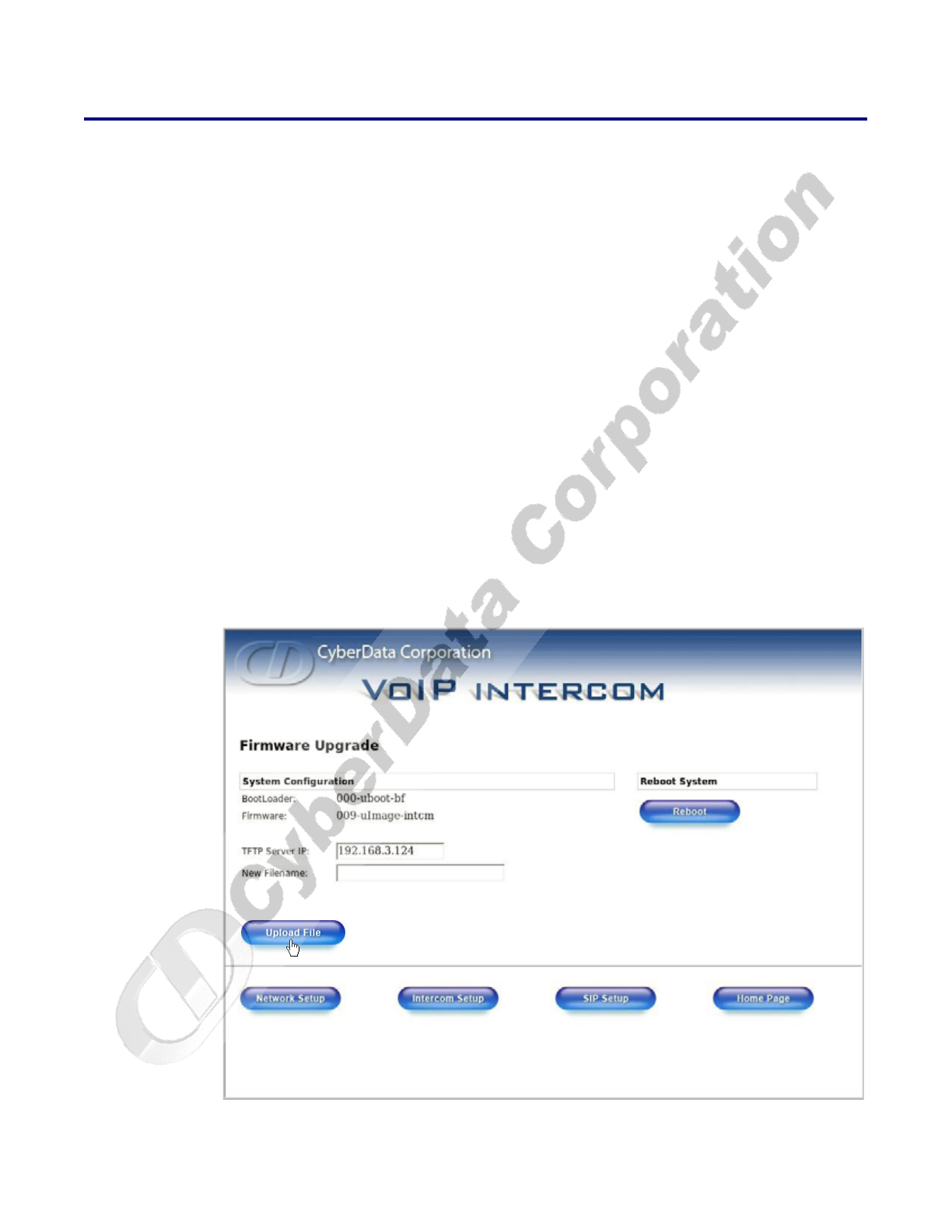
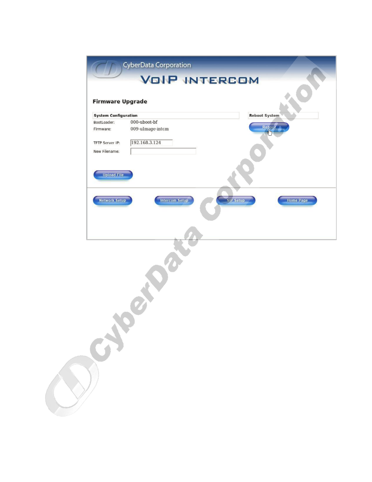
6. Click the Upgrade Firmware button to open the Firmware Upgrade page. See Figure 2-18.
Figure 2-18. Firmware Upgrade Page
7. Enter the IP address of your TFTP server into the TFTP Server IP parameter field.
Installing the VoIP Intercom
Upgrade the Firmware and Reboot the Intercom
Operations Guide 930181B CyberData Corporation
25
8. Enter the firmware filename of the file to be uploaded into the New Filename parameter field.
For example, kernel filename "201-image-spk-sip.bin".
9. Click Upload File.
Note This starts the upload process. Once the Intercom has uploaded the file, the Uploading
Firmware countdown page appears, indicating that the firmware is being written to flash.
The Intercom will automatically reboot when the upload is complete. When the countdown
finishes, the Firmware Upgrade page will refresh. The uploaded firmware filename should
be displayed in the system configuration (indicating successful upload and reboot).
10. Repeat steps 8 and 9 if you are uploading the Kernel and Application files.
For example, Application filename "201-romdisk-spk-sip.img".
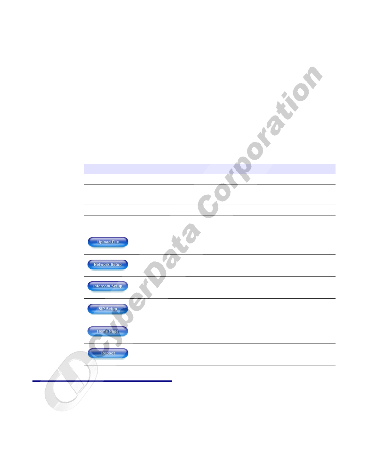
Table 2-9 shows the web page items on the Firmware Upgrade page.
2.4.1 Reboot the Intercom
To reboot a Intercom, log in to the web page as instructed in Section 2.3.1, "Log in to the
Configuration Home Page".
1. Click Upgrade Firmware to open the Firmware Upgrade page (Figure 2-19).
Table 2-9. Firmware Upgrade Parameters
Web Page Item Description
System Configuration Shows the current configuration.
BootLoader Shows the current boot loader filename.
Firmware Shows the firmware for partition 1 and 2.
TFTP Server IP Enter the TFTP Server IP address.
New Filename Use this field to enter the new file name for the kernel or
application firmware file that you are uploading.
Click on this button to automatically upload the selected
firmware and reboot the system.
Link to the Network Setup page.
Link to the Intercom Setup page.
Link to go to the SIP Setup page.
Link to the Home page.
Click on this button to reboot the system.
CyberData Corporation 930181B Operations Guide
Installing the VoIP Intercom
Upgrade the Firmware and Reboot the Intercom
26
Figure 2-19. Reboot System Section
2. Click Reboot. A normal restart will occur.
27
Operations Guide 930181B CyberData Corporation
Appendix A: Mounting the Intercom
A.1 Mount the Intercom
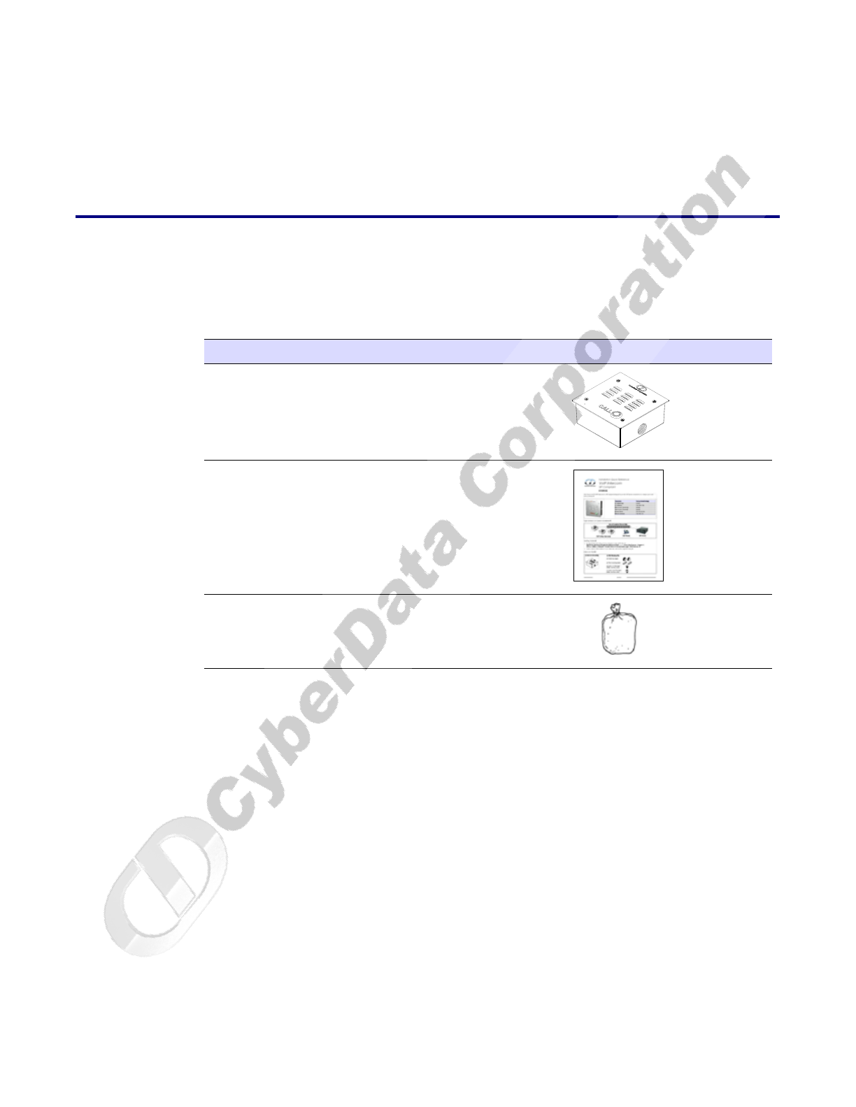
Before you mount the Intercom, make sure that you have received all the parts for each Intercom.
Refer to Table A-1.
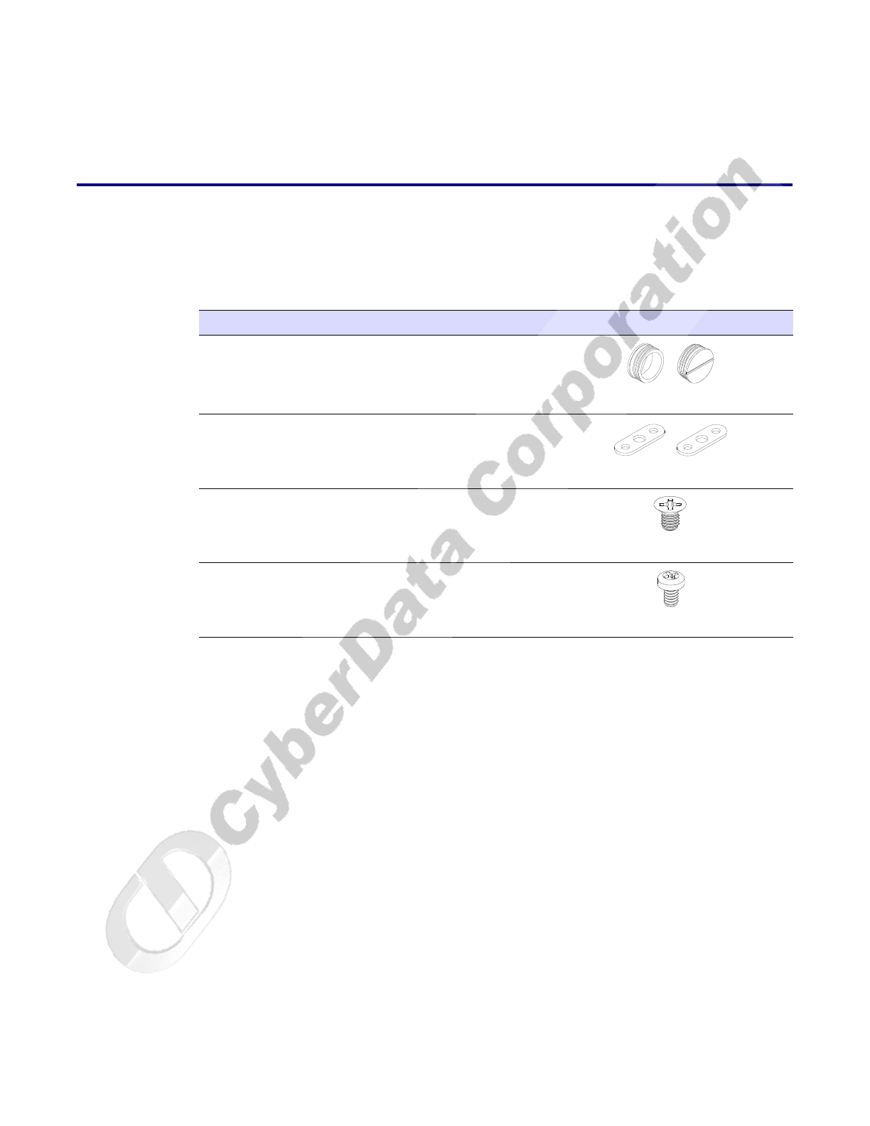
Table A-1. Drop Ceiling Mounting Components (Part of the Accessory Kit)
Quantity Part Name Illustration
2Outlet Box Plugs
2Flush Mounting Plate
28-32 x 1/4" Flat Head Phillips Machine Screw
110-24 x 5/16" Pan Head Phillips Machine
Screw
CyberData Corporation 930181B Operations Guide
Mount the Intercom
28
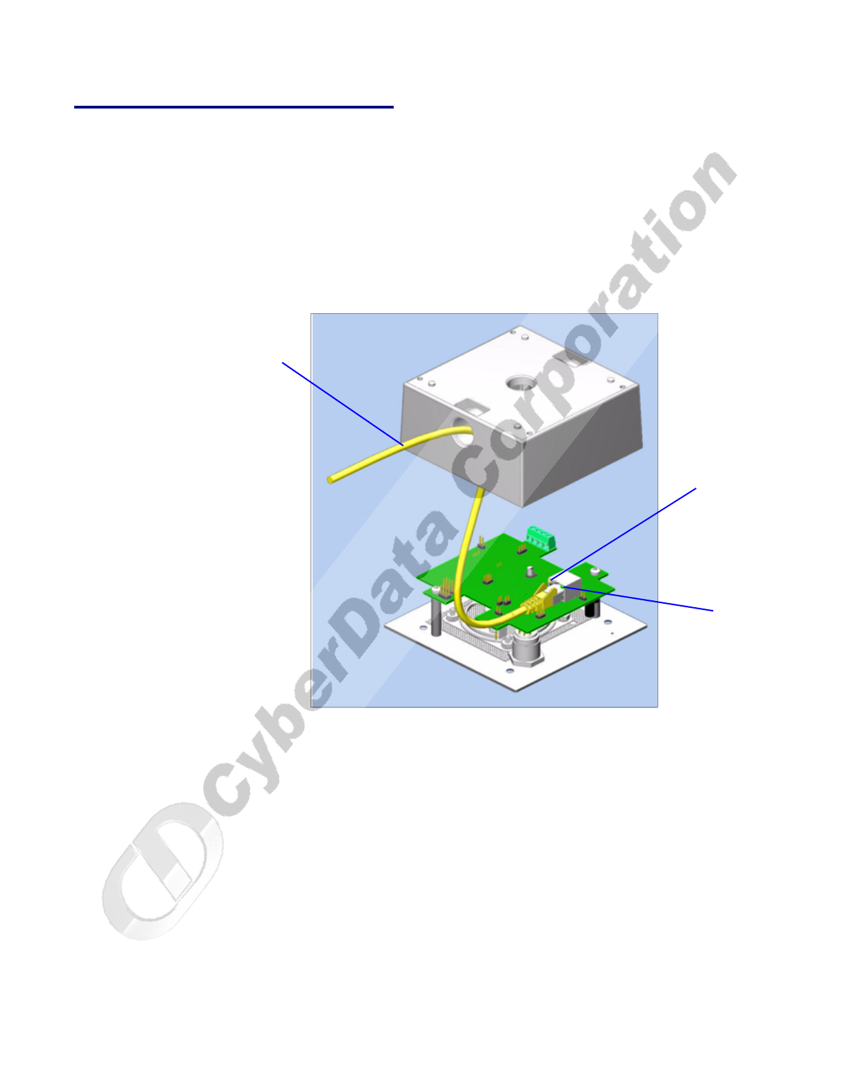
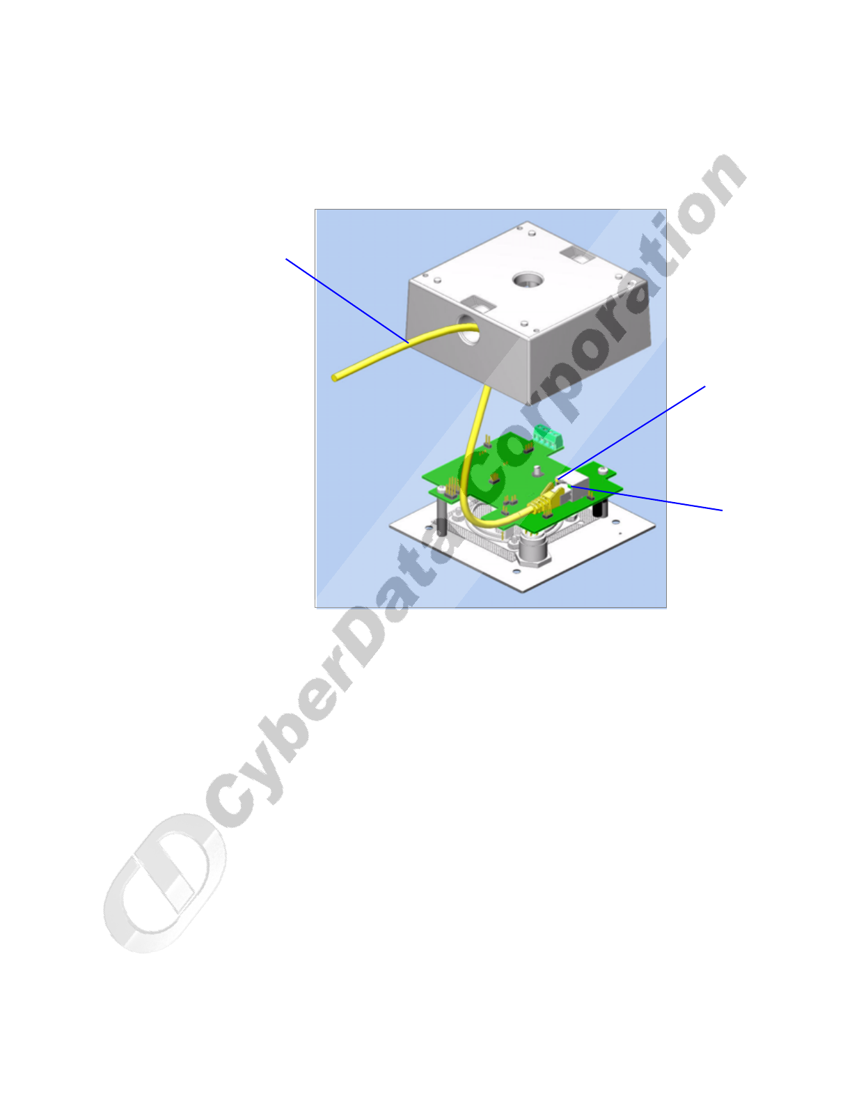
To mount the Intercom:
1. Plug the Ethernet cable into the Intercom Assembly (see Figure A-1). Section 2.2.5, "Network
Connectivity, and Data Rate" explains how the Link and Status LEDs work.
Figure A-1. Network Connector Prior to Installation
Link
Activity
Ethernet
Mount the Intercom
Operations Guide 930181B CyberData Corporation
29
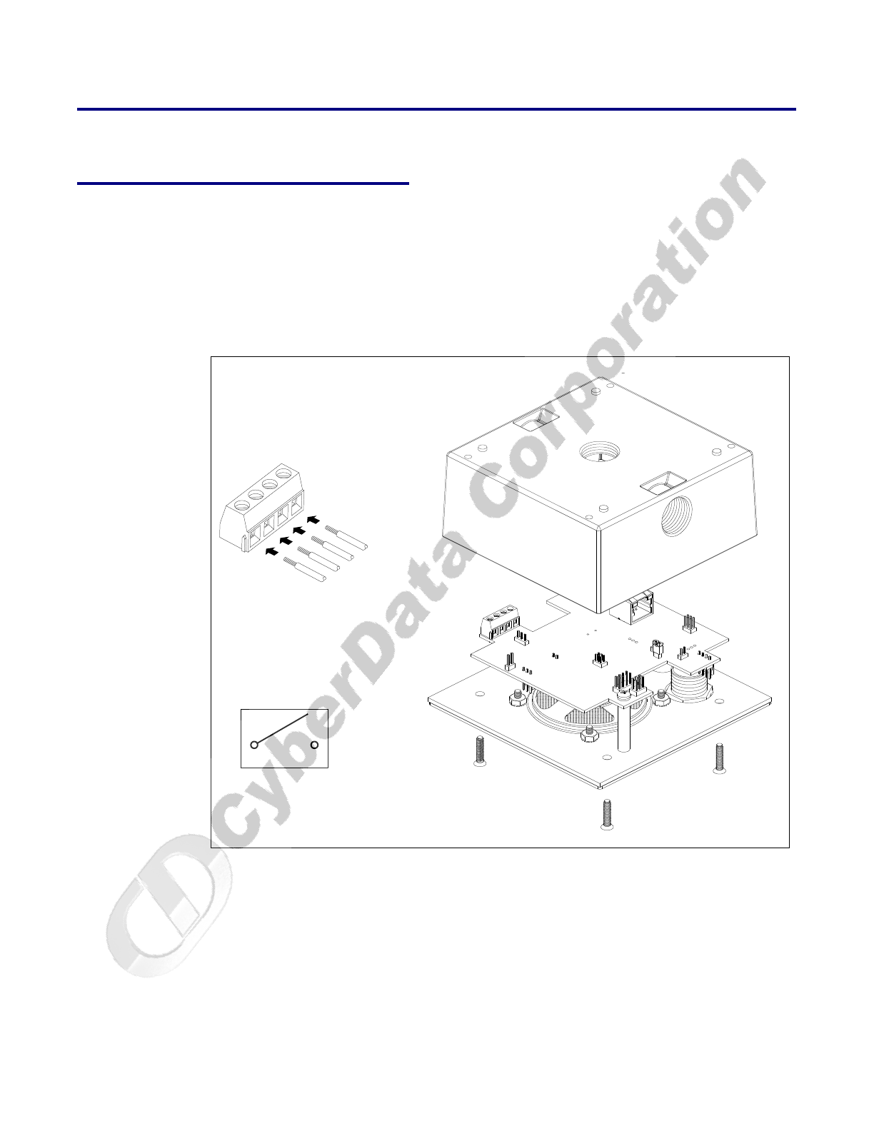
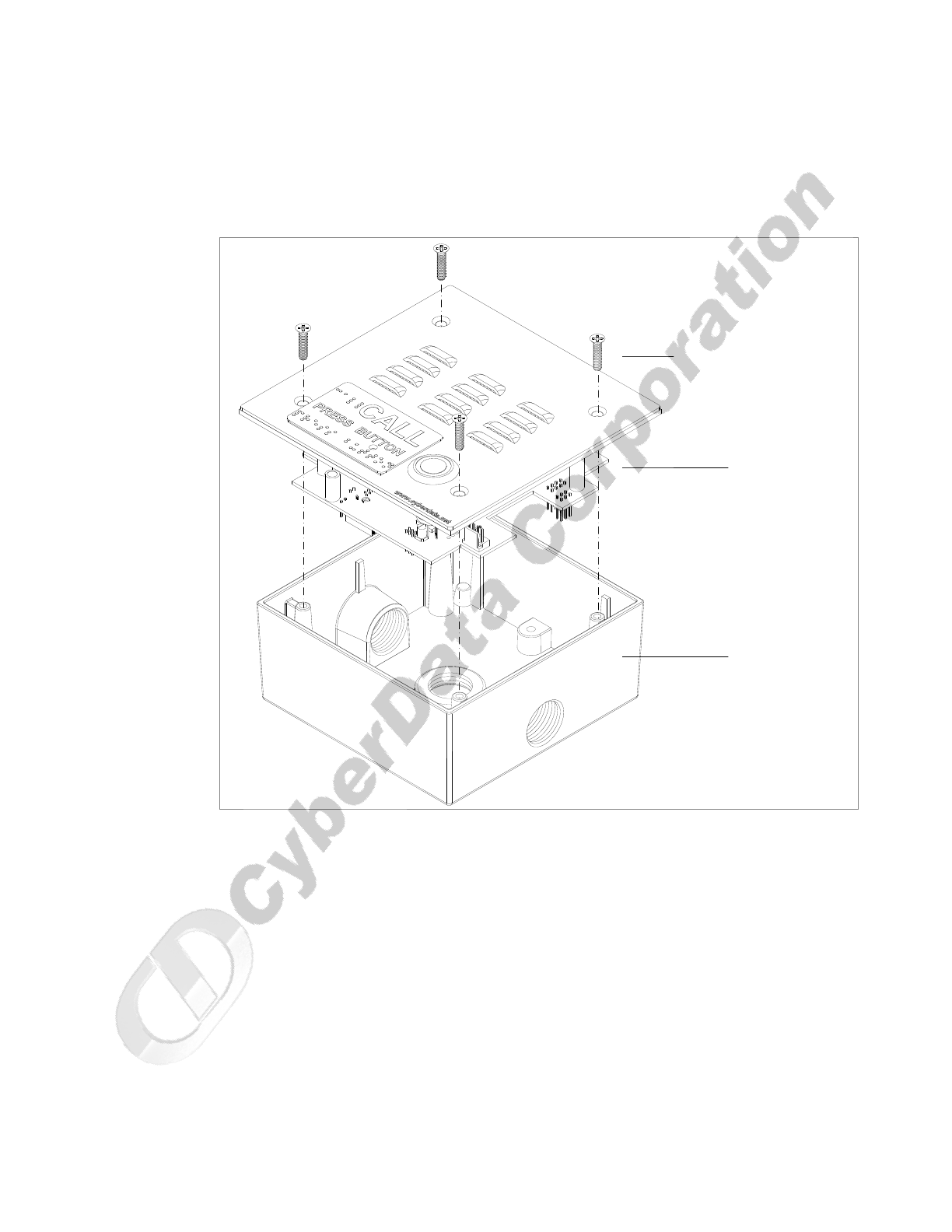
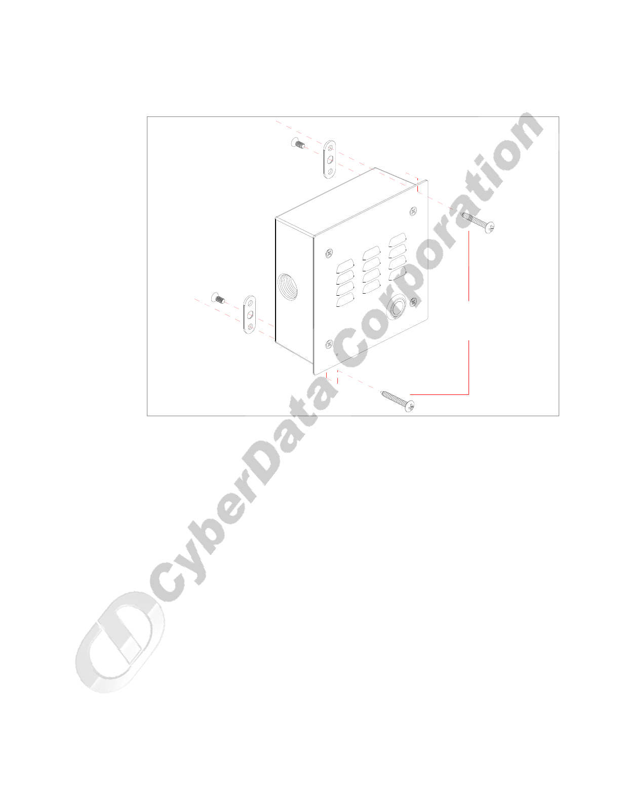
2. To fasten the Intercom:
• For wall mounting, use the two 8-32 X 1/4" FLAT HEAD PHILLIPS MACHINE SCREW
and the one 10-24 X 5/16" PAN HEAD PHILLIPS MACHINE SCREW to secure the
Intercom.
Figure A-1. VoIP Intercom Assembly
4 x Mounting Screw
Face Plate
2 Gang Box
and
PCB Assembly
CyberData Corporation 930181B Operations Guide
Mount the Intercom
30
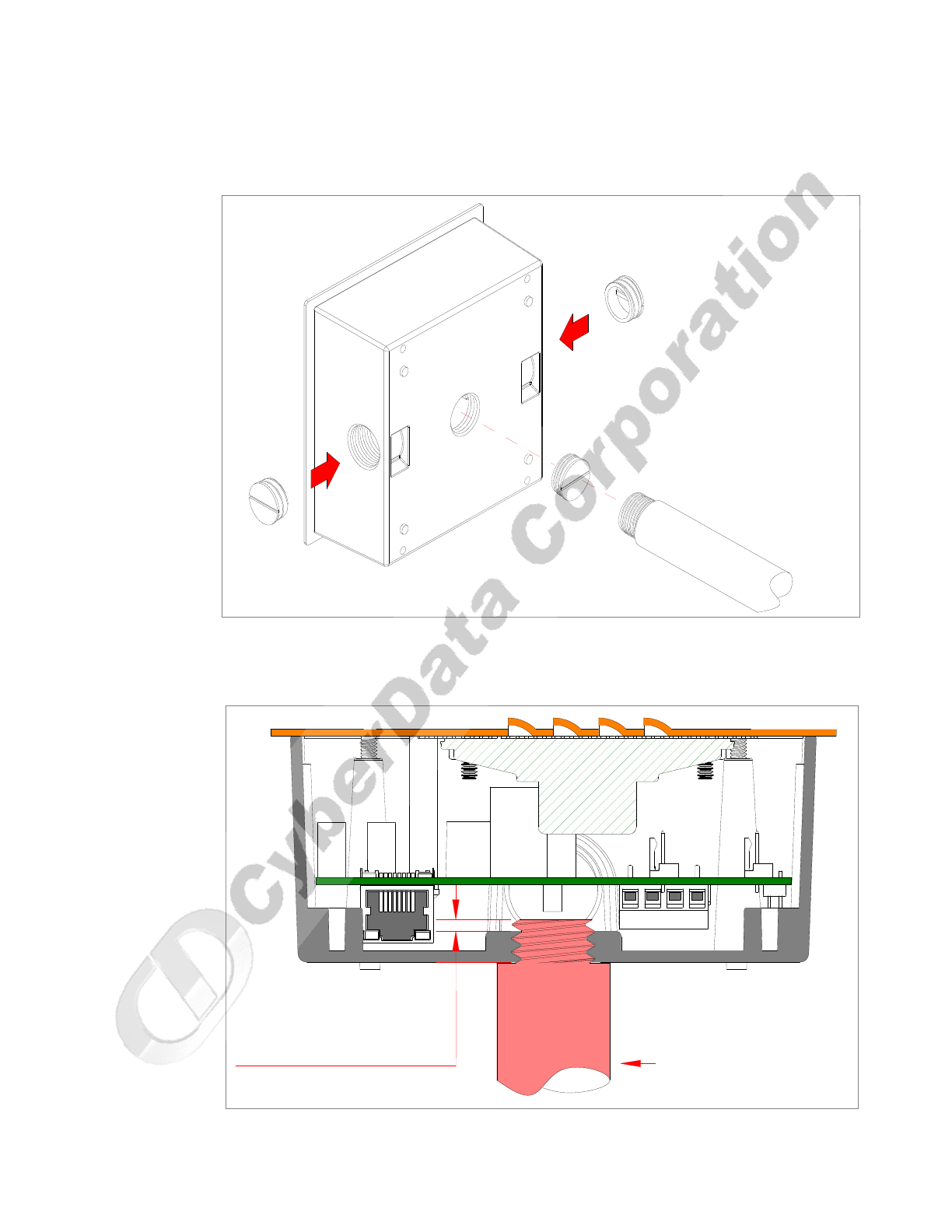
If the thread on the conduit is longer than 3/8 inch, then a stop nut (not supplied) is required.
Otherwise, use the outlet box plug to plug the exit hole.
Figure A-2. Mounting the VoIP Intercom Assembly
Figure A-3 shows the restrictions of the pipe going into the box.
Figure A-3. Pipe Restrictions
OR
CONDUIT
HOLE PLUG
Not to Exceed 0.1" CONDUIT

CyberData Corporation 930181B Operations Guide
Mount the Intercom
32

33
Operations Guide 930181B CyberData Corporation
Appendix B: Setting up a TFTP Server
B.1 Set up a TFTP Server
Upgrading the VoIP Intercom firmware requires a TFTP server on which you access the Web
interface where you can upload the firmware files.
B.1.1 In a LINUX Environment
To set up a TFTP server on LINUX:
1. Create a directory dedicated to the TFTP server, and move the files to be uploaded to that
directory.
2. Run the following command where /tftpboot/ is the path to the directory you created in
Step 1: the directory that contains the files to be uploaded. For example:
in.tftpd -l -s /tftpboot/your_directory_name
B.1.2 In a Windows Environment
You can find several options online for setting up a Windows TFTP server. This example explains
how to use the Solarwinds freeware TFTP server, which you can download at:
http://www.tucows.com/preview/326445
To set up a TFTP server on Windows:
1. Install and start the software.
2. Select File/Configure/Security tab/Transmit Only.
3. Make a note of the default directory name, and then move the firmware files to be uploaded to
that directory.
B.1.3 In a Solarwinds Server Environment
You can find several options online for setting up a Solarwinds server. This example explains how to
use the Solarwinds freeware TFTP server, which you can download at:
http://www.cyberdata.net/support/voip/solarwinds.html

CyberData Corporation 930181B Operations Guide
Set up a TFTP Server
34

35
Operations Guide 930181B CyberData Corporation
Appendix C: Troubleshooting/Technical
Support
C.1 Frequently Asked Questions (FAQ)
Go to the following URL to see CyberData’s list of frequently asked questions:
http://www.CyberData.net/support/voip
C.2 Documentation
The documentation for this product is released in an English language version only. You can
download PDF copies of CyberData product documentation at:
www.CyberData.net—>Support—>Drivers, Utilities & Manuals—>VoIP Products
C.3 Contact Information
Contact CyberData Corporation
2555 Garden Road
Monterey, CA 93940
USA
www.CyberData.net
Phone: 800-CYBERDATA (800-292-3732)
Fax: 831-373-4193
Sales Sales 831-373-2601 Extension 334
Technical
Support
Phone: 831-373-2601 Extension 333
Email: support@CyberData.net
Returned
Materials
Authorization
To return the product, contact the CyberData Returned Materials Authorization (RMA) department
at:
Phone: 831-373-2601, Extension 136
Email: RMA@CyberData.net
When returning a product to CyberData, an approved CyberData RMA number must be printed on
the outside of the original shipping package. No product will be accepted for return without an
approved RMA number. Send the product, in its original package, to the following address:
CyberData Corporation
2555 Garden Road
Monterey, CA 93940
Attention: RMA "your RMA number"

CyberData Corporation 930181B Operations Guide
Warranty
36
C.4 Warranty
CyberData warrants its product against defects in material or workmanship for a period of two
years from the date of purchase. Should the product fail within the warranty period, CyberData will
repair or replace the product free of charge. This warranty includes all parts and labor.
If the product is out-of-warranty and fails, a flat rate repair charge of one half the product purchase
price will be assessed. Repair costs for products that are in warranty, but damaged by improper
modifications or abuse, will be charged at the out-of-warranty rate. Products returned to CyberData,
both in and out-of-warranty, are shipped to CyberData at the expense of the customer. Charges for
shipping repaired products back to the customer will be paid by CyberData.

Operations Guide 930181B CyberData Corporation
37
Index
Numerics
100 Mbps indicator light 11
A
AC voltages 2, 7
act light 12
address, configuration login 16
announcing a intercom’s IP address 13, 14, 15
asterisk 19
audio encodings 4
auxiliary relay 20, 21
B
baud rate
verifying 11
C
changing
the web access password 20
configurable parameters 17, 18, 20, 22, 25
configuration
default IP settings 16
network 18
SIP 22
using Web interface 16
configuration home page 16
CyberData contact information, corporate, sales, tech
support, service 35
D
default
gateway 16
intercom settings 37
IP address 14, 16
subnet mask 14, 16
username and password 14, 16
web login username and password 16
default gateway 16, 19
default intercom settings 14
default IP settings 16
default login address 16
DHCP Client 3
DHCP IP addressing 18
dimensions 4
DNS server 19
dual speeds 11
E
ethernet cable 28
expiration time for SIP server lease 23
F
factory default settings 14
firmware upgrades 33
G
green link light 11
H
home page 16
http web-based configuration 3
I
illustration of intercom mounting process 27
installation, typical intercom system 1
intercom configuration
default IP settings 16
intercom configuration page
configurable parameters 17, 18, 20, 22, 25
intercom operations, verifying 20
intercom setup 20
IP address 14, 16, 18, 25
IP addressing 18
default setting 14, 16

CyberData Corporation 930181B Operations Guide
38
L
lease, SIP server expiration time 23
link LED 28
link light 11
Linux, setting up a TFTP server on 33
local SIP port 22
log in address 16
M
mounting an intercom 27
N
network activity, verifying 12
network configuration of intercom 18
network rate 4
Network Setup 18
O
orange link light 11
outbound proxy 22
P
packet time 4
part number 4
parts list 5
password
changing for web configuration access 20
for SIP server login 23
login 16
restoring the default 14, 16
port
local SIP 22
remote SIP 22
power requirement 4
product
configuring 16
mounting 27
parts list 5
product features 3
product overview
product features 3
product specifications 4
supported protocols 3
supported SIP servers 4
typical system installation 1
product specifications 4
protocols supported 3
R
reboot 25
registration and expiration, SIP server lease 23
remote SIP port 22
reset test function management switch 13
resetting the IP address to the default 27, 35
restoring factory default settings 14, 37
RMA returned materials authorization 35
RTFM jumper 9, 13, 15
RTFM jumper switch 13
RTFM switch 13, 14
RTP/AVP 4
S
server address, SIP 22
setting up a TFTP server 33
setting up an intercom 6
settings, default 14
SIP (session initiation protocol) 3
SIP Configuration 22
SIP configuration
SIP Server 22
SIP registration 23
SIP server 22
SIP servers supported 4
solarwinds 33
speaker output 4
static IP addressing 18
status LED 28
subnet mask 14, 16, 19
supported protocols 3
T
technical support, contact information 35
TFTP server 3, 33
U
unregister, from SIP server 23
user ID
for SIP server login 23

Operations Guide 930181B CyberData Corporation
39
user ID, SIP 22
username
changing for web configuration access 20
default for web configuration access 16
restoring the default 14, 16
V
verifying
baud rate 11
intercom operations 20
network activity 12
network connectivity 11
W
warranty 36
web access password 14, 16
web access username 14, 16
web configuration log in address 16
web-based intercom configuration 16
weight 4
Windows, setting up a TFTP server on 33
Y
yellow act light 12
yellow link light 11

CyberData Corporation 930181B Operations Guide
40
