Cypress Semiconductor CY8CKIT-142 CY8CKIT-142 PSoC 4 BLE Module User Manual Manual part 1
Cypress Semiconductor CY8CKIT-142 PSoC 4 BLE Module Manual part 1
Contents
- 1. Manual part 1
- 2. Manual part 2
Manual part 1


CY8CKIT-042-BLE Bluetooth® Low Energy (BLE) Pioneer Kit Guide, Doc. # 001-93731 Rev. *A 2
Copyrights
© Cypress Semiconductor Corporation, 2014. The information contained herein is subject to change without notice. Cypress
Semiconductor Corporation assumes no responsibility for the use of any circuitry other than circuitry embodied in a Cypress
product. Nor does it convey or imply any license under patent or other rights. Cypress products are not warranted nor
intended to be used for medical, life support, life saving, critical control or safety applications, unless pursuant to an express
written agreement with Cypress. Furthermore, Cypress does not authorize its products for use as critical components in life-
support systems where a malfunction or failure may reasonably be expected to result in significant injury to the user. The
inclusion of Cypress products in life-support systems application implies that the manufacturer assumes all risk of such use
and in doing so indemnifies Cypress against all charges.
Any Source Code (software and/or firmware) is owned by Cypress Semiconductor Corporation (Cypress) and is protected by
and subject to worldwide patent protection (United States and foreign), United States copyright laws and international treaty
provisions. Cypress hereby grants to licensee a personal, non-exclusive, non-transferable license to copy, use, modify, create
derivative works of, and compile the Cypress Source Code and derivative works for the sole purpose of creating custom
software and or firmware in support of licensee product to be used only in conjunction with a Cypress integrated circuit as
specified in the applicable agreement. Any reproduction, modification, translation, compilation, or representation of this
Source Code except as specified above is prohibited without the express written permission of Cypress.
Disclaimer: CYPRESS MAKES NO WARRANTY OF ANY KIND, EXPRESS OR IMPLIED, WITH REGARD TO THIS
MATERIAL, INCLUDING, BUT NOT LIMITED TO, THE IMPLIED WARRANTIES OF MERCHANTABILITY AND FITNESS
FOR A PARTICULAR PURPOSE. Cypress reserves the right to make changes without further notice to the materials
described herein. Cypress does not assume any liability arising out of the application or use of any product or circuit
described herein. Cypress does not authorize its products for use as critical components in life-support systems where a
malfunction or failure may reasonably be expected to result in significant injury to the user. The inclusion of Cypress’ product
in a life-support systems application implies that the manufacturer assumes all risk of such use and in doing so indemnifies
Cypress against all charges.
Use may be limited by and subject to the applicable Cypress software license agreement.
CySmart, F-RAM, PRoC, Programmable System-on-Chip, and PSoC Creator are trademarks, and PSoC and CapSense are
registered trademarks of Cypress Semiconductor Corporation. All other products and company names mentioned in this
document may be the trademarks of their respective holders.
Purchase of I2C components from Cypress or one of its sublicensed Associated Companies conveys a license under the
Philips I2C Patent Rights to use these components in an I2C system, provided that the system conforms to the I2C Standard
Specification as defined by Philips. As from October 1st, 2006 Philips Semiconductors has a new trade name - NXP
Semiconductors.
Flash Code Protection
Cypress products meet the specifications contained in their particular Cypress Datasheets. Cypress believes that its family of
products is one of the most secure families of its kind on the market today, regardless of how they are used. There may be
methods, unknown to Cypress, that can breach the code protection features. Any of these methods, to our knowledge, would
be dishonest and possibly illegal. Neither Cypress nor any other semiconductor manufacturer can guarantee the security of
their code. Code protection does not mean that we are guaranteeing the product as “unbreakable.”
Cypress is willing to work with the customer who is concerned about the integrity of their code. Code protection is constantly
evolving. We at Cypress are committed to continuously improving the code protection features of our products.

CY8CKIT-042-BLE Bluetooth® Low Energy (BLE) Pioneer Kit Guide, Doc. # 001-93731 Rev. *A 3
Contents
Safety Information 6
1. Introduction 11
1.1 Kit Contents ...............................................................................................................11
1.2 Board Details .............................................................................................................12
1.3 PSoC Creator™.........................................................................................................15
1.4 Getting Started...........................................................................................................16
1.5 Additional Learning Resources..................................................................................16
1.5.1 Beginner Resources.......................................................................................16
1.5.2 Application Notes ...........................................................................................16
1.5.3 PSoC Creator Example Projects....................................................................17
1.5.4 Component Datasheets .................................................................................17
1.5.5 Bluetooth Learning Resources.......................................................................17
1.5.6 Learning From Peers .....................................................................................17
1.5.7 Other Related Resources...............................................................................18
1.6 Technical Support......................................................................................................18
1.7 Documentation Conventions......................................................................................18
1.8 Acronyms...................................................................................................................19
2. Software Installation 20
2.1 Before You Begin.......................................................................................................20
2.2 Install Software ..........................................................................................................20
2.3 Uninstall Software......................................................................................................23
3. Kit Operation 24
3.1 Theory of Operation...................................................................................................24
3.2 BLE Pioneer Kit USB Connection..............................................................................26
3.3 Placing Modules on Baseboard .................................................................................26
3.4 Programming and Debugging BLE Device ................................................................27
3.4.1 Programming and Debugging using PSoC Creator .......................................27
3.4.2 Programming using PSoC Programmer.........................................................30
3.5 Updating BLE Dongle for CySmart PC Tool ..............................................................33
3.6 USB-UART Bridge .....................................................................................................36
3.7 USB-I2C Bridge .........................................................................................................37
3.8 Updating the Onboard PSoC 5LP Programmer Firmware.........................................40
3.9 Measure Coin Cell Power Consumption....................................................................40
4. Example Projects 42
4.1 Using Example Projects.............................................................................................42
4.2 CapSense Slider and LED.........................................................................................47
4.2.1 Project Description.........................................................................................47
4.2.2 Hardware Connections...................................................................................50

CY8CKIT-042-BLE Bluetooth® Low Energy (BLE) Pioneer Kit Guide, Doc. # 001-93731 Rev. *A 4
Contents
4.2.3 Flow Chart......................................................................................................51
4.2.4 Verify Output ..................................................................................................52
4.3 CapSense Proximity ..................................................................................................62
4.3.1 Project Description.........................................................................................62
4.3.2 Hardware Connections...................................................................................64
4.3.3 Flow Chart......................................................................................................66
4.3.4 Verify Output ..................................................................................................67
4.4 BLE Central Mode .....................................................................................................73
4.4.1 Project Description.........................................................................................73
4.4.2 Hardware Connections...................................................................................76
4.4.3 Flow Chart......................................................................................................77
4.4.4 Verify Output ..................................................................................................78
4.5 BLE Dongle and LED Control ....................................................................................81
4.5.1 Project Description.........................................................................................81
4.5.2 Hardware Connections...................................................................................82
4.5.3 Flow Chart......................................................................................................83
4.5.4 Verify Output ..................................................................................................84
4.6 Direct Test Mode (DTM) ............................................................................................84
4.6.1 Project Description.........................................................................................84
4.6.2 Hardware Connection ....................................................................................86
4.6.3 Verify Output ..................................................................................................87
5. Hardware 88
5.1 Pioneer Baseboard....................................................................................................88
5.1.1 PSoC 5LP ......................................................................................................88
5.1.2 Power System................................................................................................88
5.1.3 Programming Interface...................................................................................94
5.1.4 Expansion Connectors ...................................................................................95
5.1.5 USB Mini-B Connector...................................................................................98
5.1.6 CapSense Circuit ...........................................................................................99
5.1.7 Pioneer Board LEDs ....................................................................................101
5.1.8 Push Buttons................................................................................................102
5.1.9 Cypress Ferroelectric RAM (F-RAM) ...........................................................103
5.1.10 Serial Interconnection Between PSoC 5LP and BLE Module......................104
5.1.11 Bluetooth Module Headers...........................................................................105
5.2 BLE Module Board...................................................................................................106
5.2.1 PSoC 4 BLE or PRoC BLE ..........................................................................106
5.2.2 Bluetooth Module Headers (20-Pin and 24-Pin Headers)............................107
5.2.3 Wiggle Antenna............................................................................................108
5.2.4 Antenna Matching Network..........................................................................109
5.2.5 BLE Passives...............................................................................................110
5.2.6 Test Points.................................................................................................... 111
5.3 BLE Dongle Board...................................................................................................111
5.3.1 Power System..............................................................................................112
5.3.2 USB Type A Plug .........................................................................................113
5.3.3 User LED......................................................................................................114
6. Advanced Topics 115
6.1 Using PSoC 5LP as USB-UART Bridge ..................................................................115
6.2 Using PSoC 5LP as USB-I2C Bridge ......................................................................126
6.3 Developing Applications for PSoC 5LP ...................................................................134
6.3.1 Building a Bootloadable Project for PSoC 5LP ............................................134

CY8CKIT-042-BLE Bluetooth® Low Energy (BLE) Pioneer Kit Guide, Doc. # 001-93731 Rev. *A 5
Contents
6.3.2 Building a Normal Project for PSoC 5LP......................................................143
6.4 PSoC 5LP Factory Program Restore Instructions ...................................................144
6.4.1 PSoC 5LP is Programmed with a Bootloadable Application ........................144
6.5 Using FM24V10 F-RAM...........................................................................................150
6.5.1 Address Selection ........................................................................................151
6.5.2 Write/Read Operation ..................................................................................151
6.6 CySmart iOS/Android Application............................................................................152
6.7 CySmart PC Tool.....................................................................................................160
A. Appendix 168
A.1 Schematics ..............................................................................................................168
A.2 Board Layout ...........................................................................................................176
A.3 Bill of Materials (BOM).............................................................................................184
A.4 KitProg Status LED States.......................................................................................194
A.5 Adding BLE module compatible headers on your own baseboard..........................195
Revision History 196
CY8CKIT-042-BLE Bluetooth® Low Energy (BLE) Pioneer Kit Guide, Doc. # 001-93731 Rev. *A 6
Safety Information
The CY8CKIT-042-BLE Bluetooth Low Energy (BLE) Pioneer Kit is intended for use as a
development platform for hardware or software in a laboratory environment. The board is an open
system design, which does not include a shielded enclosure. Due to this reason, the board may
cause interference with other electrical or electronic devices in close proximity. In a domestic
environment, this product may cause radio interference. In such cases, the user may be required to
take adequate preventive measures. Also, this board should not be used near any medical
equipment or critical RF devices.
The CY8CKIT-042-BLE Bluetooth Low Energy (BLE) Pioneer Kit is intended for use as a
development, demonstration and evaluation platform for hardware or software in a laboratory
environment. The kit is not intended for general consumer use. Cypress recommends that the kit
only be used in a shielded room.
Attaching additional wiring to this product or modifying the product operation from the factory default
may affect its performance and cause interference with other apparatus in the immediate vicinity. If
such interference is detected, suitable mitigating measures should be taken.
The CY8CKIT-042-BLE boards contain electrostatic discharge (ESD)
sensitive devices. Electrostatic charges readily accumulate on the
human body and any equipment, which can cause a discharge without
detection. Permanent damage may occur on devices subjected to
high-energy discharges. Proper ESD precautions are recommended
to avoid performance degradation or loss of functionality. Store unused
CY8CKIT-042-BLE boards in the protective shipping package.
End-of-Life/Product Recycling
The end-of-life cycle for this kit is five years from the date of
manufacture mentioned on the back of the box. Contact your nearest
recycler to discard the kit.

CY8CKIT-042-BLE Bluetooth® Low Energy (BLE) Pioneer Kit Guide, Doc. # 001-93731 Rev. *A 7
General Safety Instructions
ESD Protection
ESD can damage boards and associated components. Cypress recommends that the user perform
procedures only at an ESD workstation. If an ESD workstation is not available, use appropriate ESD
protection by wearing an antistatic wrist strap attached to the chassis ground (any unpainted metal
surface) on the board when handling parts.
Handling Boards
CY8CKIT-042-BLE boards are sensitive to ESD. Hold the board only by its edges. After removing
the board from its box, place it on a grounded, static-free surface. Use a conductive foam pad if
available. Do not slide the board over any surface.
Battery Care and Use
■Use the correct size and type of battery specified in this guide.
■Keep battery contact surfaces and battery compartment contacts clean by rubbing them with a
clean pencil eraser or a rough cloth each time you replace batteries.
■Remove the battery from a device when it is not expected to be in use for several months.
■Make sure that you insert the battery into your device properly, with the + (plus) and – (minus)
terminals aligned correctly.
■Do not place the battery next to metallic objects such as keys and coins.
■Never throw the battery into fire.
■Do not open up the battery.
■Do not short the battery.
■Do not subject the battery to high temperatures or high humidity.
■Store the battery in a dry place.
■Do not recharge a battery unless it is marked “rechargeable.”
Battery Disposal
Batteries can be safely disposed of with normal household waste. Never dispose of batteries in fire
because they can explode. It is important not to dispose of large amounts of batteries in a group.
Used batteries are often not completely “dead.” Grouping used batteries together can bring these
“live” batteries into contact with one another, creating safety risks.

CY8CKIT-042-BLE Bluetooth® Low Energy (BLE) Pioneer Kit Guide, Doc. # 001-93731 Rev. *A 8
Regulatory Compliance Information
The kit contains devices that transmit and receive radio signals in accordance with the spectrum
regulations for the 2.4-GHz unlicensed frequency range.
Cypress Semiconductor Corporation has obtained regulatory approvals for this kit to be used in
specific countries. These countries include United States (FCC Part 15), Canada (IC RSS210) and
Japan (JRF/ TELEC). Additional regional regulatory agency approval may be required to operate
these throughout the world.
This kit as shipped from the factory has been tested and found to comply with the limits/
requirements for following compliances:
■FCC as a class B digital device, pursuant to part 15 of the FCC Rules.
■This Class B digital apparatus complies with Canadian ICES-003
Regulatory statements and Product Labeling
United States (FCC)
This equipment complies with Part 15 of the FCC Rules. Operation is subject to the following two
conditions: (1) this device may not cause harmful interference, and (2) this device must accept any
interference received, including interference that may cause undesired operation.
The CY8CKIT-142 PSoC 4 BLE and CY5671 PRoC BLE modular transmitter must be labeled with
its own FCC ID number, and, if the FCC ID is not visible when the module is installed in to another
device, then the outside of the device into which the module is installed must also display a label
referring to the enclosed module. This exterior label can use wording such as the following:
Contains FCC ID: WAP-CY8CKIT-142 and WAP-CY5671, The enclosed device complies with Part
15 of the FCC Rules. Operation is subject to the following two conditions: (1) This device may not
cause harmful interference and (2) this device must accept any interference received, including
interference that may cause undesired operation. Any similar wording that expresses the same
meaning may be used.
CAUTION: Any changes or modifications not expressly approved by
the party responsible for compliance could void the user’s authority to
operate the equipment.
Only the PCB antenna(s) that were certified with the module may be
used. Other antennas may be used only if they are of the same type
and have the same or lower gain.
The module must be recertified as a Class II permissive change if the
module is built into a different device than the EVB (evaluation board)
it was certified with
THE MANUFACTURER IS NOT RESPONSIBLE FOR ANY RADIO
OR TV INTERFERENCE CAUSED BY UNAUTHORIZED
MODIFICATIONS TO THIS EQUIPMENT. SUCH MODIFICATIONS
COULD VOID THE USER'S AUTHORITY TO OPERATE THE
EQUIPMENT.

CY8CKIT-042-BLE Bluetooth® Low Energy (BLE) Pioneer Kit Guide, Doc. # 001-93731 Rev. *A 9
CAUTION: The changes or modifications not expressly approved by the party responsible for
Compliance could void the user’s authority to operate the equipment and must not be co-located
or operating in conjunction with any other antenna or transmitter.
Canada (IC)
This device complies with Industry Canada license-exempt RSS standard(s). Operation is subject to
the following two conditions: (1) this device may not cause interference, and (2) this device must
accept any interference, including interference that may cause undesired operation of the device.
This equipment complies with radio frequency exposure limits set forth by Industry Canada for an
uncontrolled environment.
CAUTION: Any changes or modifications not expressly approved by the party responsible for com-
pliance could void the user’s authority to operate the equipment.
This Module is labelled with its own IC ID. If the IC ID Certification Number is not visible while
installed inside another device, then the device should display the label on it referring the enclosed
module. In that case, the final end product must be labelled in a visible area with the following:
“Contains Transmitter Module IC 7922A-CY8CKIT142 and 7922A-CY5671”
OR
“Contains IC: 7922A-CY8CKIT142 and 7922A-CY5671”
Le présent appareil est conforme aux CNR d'Industrie Canada applicables aux appareils radio
exempts de licence. L'exploitation est autorisée aux deux conditions suivantes: (1) l'appareil ne doit
pas produire de brouillage, et (2) l'utilisateur de l'appareil doit accepter tout brouillage radioélectrique
subi, même si le brouillage est susceptible d'en compromettre le fonctionnement.
Cet équipement est conforme aux limites d'exposition aux radiofréquences définies par Industrie
Canada pour un environnement non contrôlé.
Ce module est étiqueté avec son propre ID IC. Si le numéro de certification IC ID n'est pas visible
lorsqu'il est installé à l'intérieur d'un autre appareil, l'appareil doit afficher l'étiquette sur le module de
référence ci-joint. Dans ce cas, le produit final doit être étiqueté dans un endroit visible par le texte
suivant:
“Contains Transmitter Module IC 7922A-CY8CKIT142 and 7922A-CY5671”
OR
“Contains IC: 7922A-CY8CKIT142 and 7922A-CY5671”
CY8CKIT-042-BLE Bluetooth® Low Energy (BLE) Pioneer Kit Guide, Doc. # 001-93731 Rev. *A 10
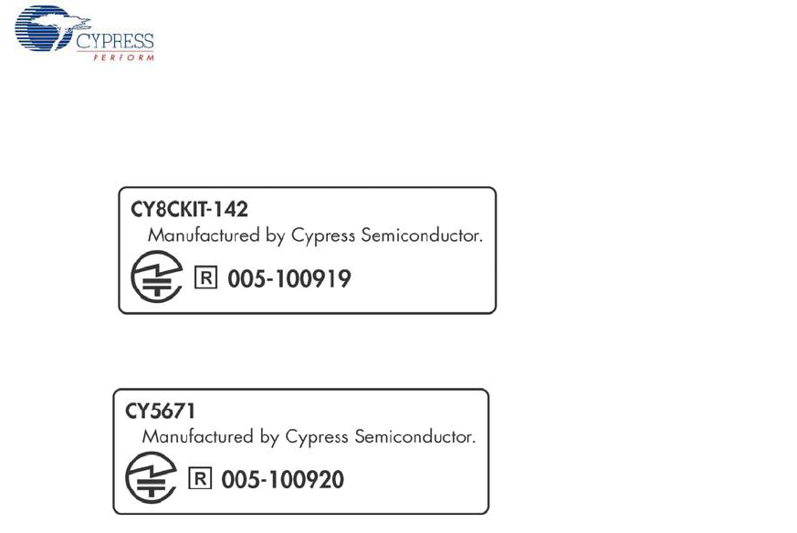
Japan (TELEC)
Model:CY5671
FCC ID: WAP-CY5671
IC: 7922A-CY5671
TELEC: 005-100920
Model:CY8CKIY-142
FCC ID : WAP-CY8CKIT-142
IC : 7922A-CY8CKIT142
TELEC : 005-100919

CY8CKIT-042-BLE Bluetooth® Low Energy (BLE) Pioneer Kit Guide, Doc. # 001-93731 Rev. *A 11
1. Introduction
Thank you for your interest in the CY8CKIT-042-BLE Bluetooth® Low Energy (BLE) Pioneer Kit. This
kit is designed to showcase the functionality and ease-of-use of the PSoC® 4 BLE and PRoC™ BLE
devices while developing Bluetooth Low Energy (Bluetooth Smart) applications. Cypress's BLE solu-
tion has an easy-to-use, intuitive GUI to configure the BLE protocol stack using the BLE component
available in the Cypress standard integrated development environment (IDE), PSoC Creator. The
CySmart PC tool allows emulation of a BLE Central device and quick access to peripheral connec-
tions and debugging. The solution is a true single-chip solution with an integrated balun, Cypress's
industry-leading capacitive sensing technology, an analog front end (AFE) for biometric sensors, and
digital peripherals suited to a wide variety of applications. Designed for flexibility, this kit offers foot-
print compatibility with several third-party Arduino™ shields. The kit includes a provision to populate
an extra header to support Digilent® Pmod™ peripheral modules. In addition, the board features a
CapSense® slider, an RGB LED, a push-button switch, an integrated USB programmer, a program
and debug header, an F-RAM™, and USB-UART/I2C bridges.
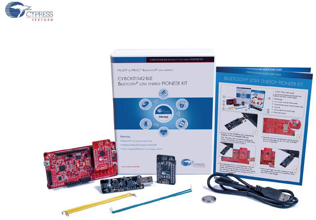
1.1 Kit Contents
The BLE Pioneer Kit contains the following items, as shown in Figure 1-1.
■BLE Pioneer Baseboard preloaded with the CY8CKIT-142 PSoC 4 BLE Module
■CY5671 PRoC BLE Module
■CY5670 CySmart USB Dongle
■Quick start guide
■USB standard A to mini-B cable
■Four jumper wires (4 inch) and two proximity sensor wires (5 inch)
■Coin cell
CY8CKIT-042-BLE Bluetooth® Low Energy (BLE) Pioneer Kit Guide, Doc. # 001-93731 Rev. *A 12
Introduction
Figure 1-1. Kit Contents
If any part of the kit is missing, contact your nearest Cypress sales office for help: www.cypress.com/
go/support.
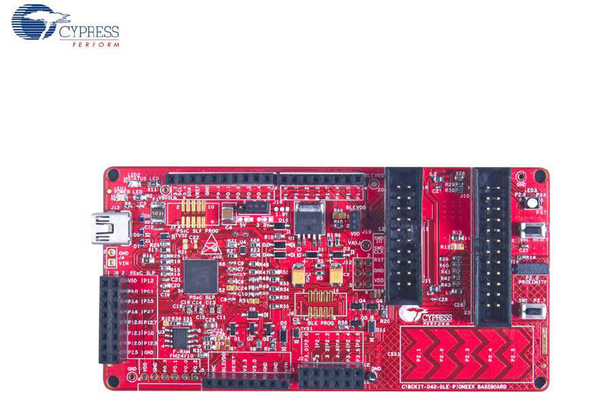
1.2 Board Details
The BLE Pioneer baseboard consists of the blocks shown in Figure 1-2.
1. RGB LED
2. BLE module reset button
3. CapSense proximity header
4. User button
5. CapSense slider
6. Arduino compatible I/O header (J2)
7. Arduino compatible power header (J1)
8. Digilent Pmod compatible I/O header (J5)
9. Cypress F-RAM 1 Mb (FM24V10-G)
10.PSoC 5LP - programmer and debugger (CY8C5868LTI-LP039)
11.PSoC 5LP I/O header (J8)
12.Coin cell holder (bottom side)
13.USB connector (J13)
14.Power LED
15.Status LED
16.System power supply jumper (J16) - LDO 1.9 V~5 V
17.Arduino compatible I/O header (J3/J4)
CY8CKIT-042-BLE Bluetooth® Low Energy (BLE) Pioneer Kit Guide, Doc. # 001-93731 Rev. *A 13
Introduction
18.BLE power supply jumper (J15) - for current measurement
19.BLE module headers (J10/J11)
Figure 1-2. BLE Pioneer Baseboard
CY8CKIT-042-BLE Bluetooth® Low Energy (BLE) Pioneer Kit Guide, Doc. # 001-93731 Rev. *A 14
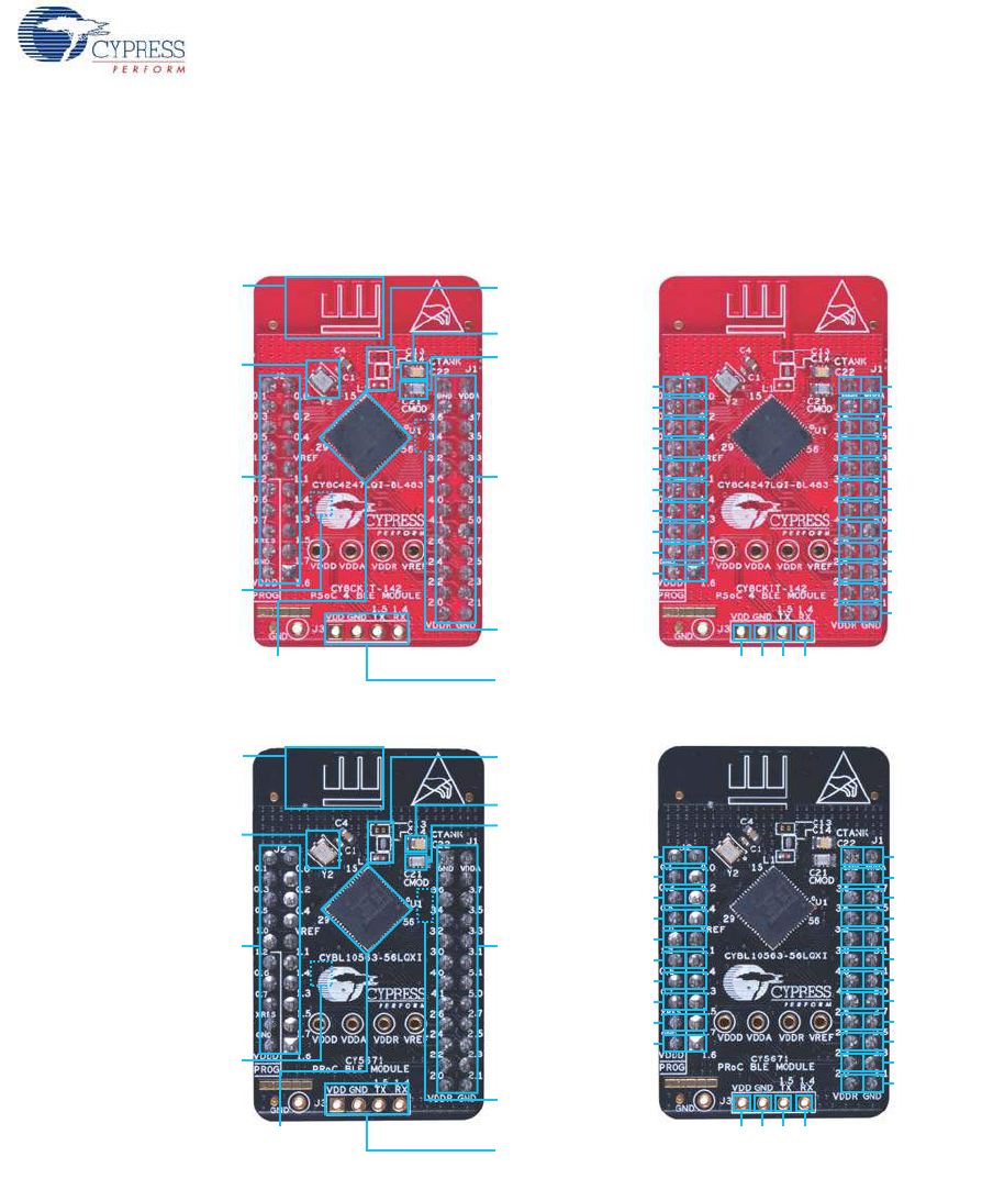
Introduction
Figure 1-3 shows a markup of the onboard components, where red BLE module denotes the PSoC 4
BLE module and black BLE module denotes the PRoC BLE module.
Figure 1-3. BLE Module Markup
(/%7%%"
1@1@
1@1@
1@1@
1@1@
1@1@
1@1@
1@1@
1@1@
1@1@
1@1@
7%%3(/%
1@1@
1@1@
1@1@
1@73&'
1@1@
1@1@
1@1@
93&41@
(/%1@
7%%%1@
7%%
(/%
1@
8JHHMF
BOUFOOB
,)[
DSZTUBM
CPUUPNTJEF
$NPE
$UBOL
"OUFOOB
NBUDIJOH
OFUXPSL"./
$:$-2*#-
14P$#-&EFWJDF
14P$
#-&NPEVMF
IFBEFS+
14P$
#-&NPEVMF
IFBEFS+
QJO6"35
IFBEFS
4"3CZQBTT
DBQBDJUPS
CPUUPNTJEF
(/%7%%"
1@1@
1@1@
1@1@
1@1@
1@1@
1@1@
1@1@
1@1@
1@1@
1@1@
7%%3(/%
1@1@
1@1@
1@1@
1@73&'
1@1@
1@1@
1@1@
93&41@
(/%1@
7%%%1@
7%%
(/%
8JHHMF
BOUFOOB
$NPE
$UBOL
"OUFOOB
NBUDIJOH
OFUXPSL"./
.)[
DSZTUBM
$:#--29*
13P$#-&EFWJDF
13P$
#-&NPEVMF
IFBEFS+
13P$
#-&NPEVMF
IFBEFS+
QJO6"35
IFBEFS
4"3CZQBTT
DBQBDJUPS
CPUUPNTJEF
1@
1@
1@
.)[
DSZTUBM
,)[
DSZTUBM
CPUUPNTJEF
CY8CKIT-042-BLE Bluetooth® Low Energy (BLE) Pioneer Kit Guide, Doc. # 001-93731 Rev. *A 15
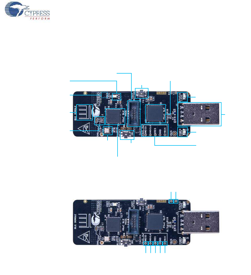
Introduction
The dongle board consists of the blocks shown in Figure 1-4.
Figure 1-4. BLE Dongle Markup
1.3 PSoC Creator™
PSoC Creator is a state-of-the-art, easy-to-use integrated design environment (IDE). It is a
revolutionary hardware and software co-design environment, powered by a library of preverified and
precharacterized PSoC Components™.
With PSoC Creator, you can:
■Drag and drop PSoC Components to build a schematic of your custom design
■Automatically place and route components and configure GPIOs
■Develop and debug firmware using the included component APIs
PSoC Creator also enables you to tap into an entire tool ecosystem with integrated compiler chains
and production programmers for PSoC devices.
For more information, visit www.cypress.com/psoccreator.
13P$#-&
SFTFUCVUUPO
$:#--29*
13P$#-&EFWJDF
14P$-1
QSPHSBNNJOHUFTUQPJOUT
$:$-5*-1
14P$-1QSPHSBNNFS
BOEEFCVHHFS
6TFSCVUUPO
1PXFS-&%
64#QMVH
4UBUVT-&%
8JHHMF
BOUFOOB
"OUFOOB
NBUDIJOH
OFUXPSL
"./
.)[DSZTUBM
6TFS-&%
13P$FYUFSOBMQSPHSBNNJOHIFBEFS
,)[
DSZTUBM
CPUUPNTJEF
48%*0
48%$-,
93&4
(/%
7#64
1@
1@

CY8CKIT-042-BLE Bluetooth® Low Energy (BLE) Pioneer Kit Guide, Doc. # 001-93731 Rev. *A 16
Introduction
1.4 Getting Started
This guide will help you get acquainted with the BLE Pioneer Kit:
■The Software Installation chapter on page 20 describes the installation of the kit software. This
includes the PSoC Creator IDE for development and debugging applications, PSoC Programmer
for programming hex files, and the CySmart PC tool for BLE host emulation.
■The Kit Operation chapter on page 24 describes the major features of the BLE Pioneer Kit such
as USB-UART and USB-I2C bridges and functionalities such as programming and debugging.
■The Example Projects chapter on page 42 describes multiple PSoC 4 BLE and PRoC BLE code
examples that will help you understand how to create your own BLE application using the BLE
component and device.
■The Hardware chapter on page 88 details the hardware content of the kit and dongle, and the
hardware operation.
■The Advanced Topics chapter on page 115 explains the functionality of the kit features, such as
the USB-UART bridge, USB-I2C bridge, F-RAM, iOS app, and the CySmart PC tool.
■The Appendix on page 168 provides schematics, board layouts, KitProg LED status, and the bill
of materials (BOM).
1.5 Additional Learning Resources
Visit www.cypress.com/go/psoc4ble and www.cypress.com/procble for additional learning resources
including datasheets, technical reference manuals, and application notes.
Visit www.cypress.com/go/cysmart for information on the CySmart PC tool.
1.5.1 Beginner Resources
PSoC Creator Training: www.cypress.com/go/creatorstart/creatortraining
1.5.2 Application Notes
Visit www.cypress.com/appnotes to view a growing list of application notes for PSoC 3, PSoC 4,
PSoC 4 BLE, PRoC BLE, and PSoC 5LP.
Visit this site for PSoC 4BLE and PRoC BLE application notes.
CY8CKIT-042-BLE Bluetooth® Low Energy (BLE) Pioneer Kit Guide, Doc. # 001-93731 Rev. *A 17
Introduction
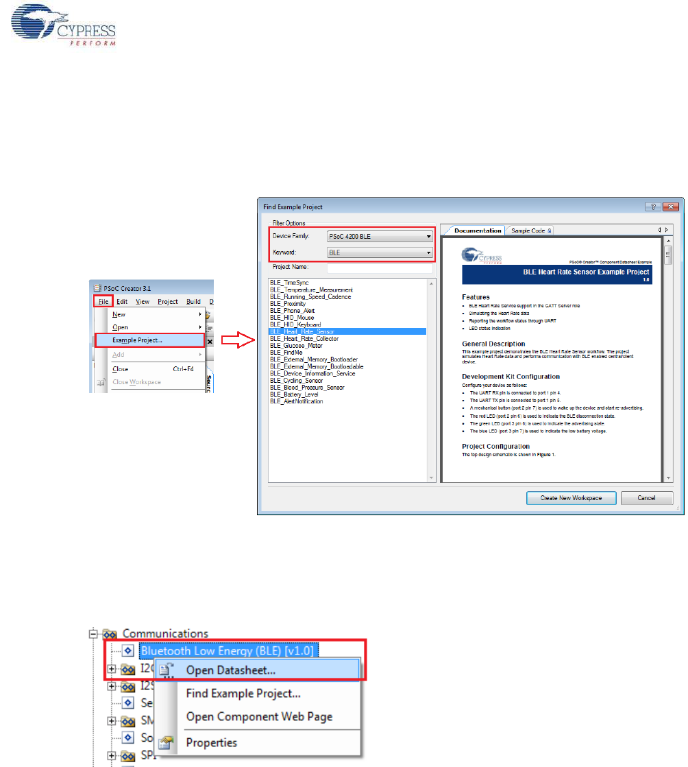
1.5.3 PSoC Creator Example Projects
These simple example projects demonstrate how to configure and use PSoC Creator components.
To open an example project in PSoC Creator, go to File > Example Project (see Figure 1-5) and
choose the required example project.
Figure 1-5. PSoC Creator Example Projects
1.5.4 Component Datasheets
Right-click a component and select Open Datasheet (see Figure 1-6). Visit this page for the BLE
component datasheet.
Figure 1-6. Opening Component Datasheet
1.5.5 Bluetooth Learning Resources
The Bluetooth Developer Portal provides material by the Special Interest Group (SIG) for learning
various aspects of the Bluetooth Low Energy protocol and systems. Some of them are:
■Training videos
■GATT profiles
■Bluetooth community forum
1.5.6 Learning From Peers
Cypress Developer Community Forums: Visit www.cypress.com/forums

CY8CKIT-042-BLE Bluetooth® Low Energy (BLE) Pioneer Kit Guide, Doc. # 001-93731 Rev. *A 18
Introduction
1.5.7 Other Related Resources
■Digilent PMod: www.digilentinc.com/pmods/
■Arduino: http://arduino.cc/en/Main/ArduinoBoardUno
1.6 Technical Support
For assistance, go to our support web page, www.cypress.com/support, or contact our customer
support at +1 (800) 541-4736 Ext. 2 (in the USA) or +1 (408) 943-2600 Ext. 2 (International).
1.7 Documentation Conventions
Table 1-1. Document Conventions for Guides
Convention Usage
Courier New Displays file locations, user entered text, and source code:
C:\...cd\icc\
Italics Displays file names and reference documentation:
Read about the sourcefile.hex file in the PSoC Creator User Guide.
[Bracketed, Bold]Displays keyboard commands in procedures:
[Enter] or [Ctrl] [C]
File > Open Represents menu paths:
File > Open > New Project
Bold Displays commands, menu paths, and icon names in procedures:
Click the File icon and then click Open.
Times New Roman Displays an equation:
2 + 2 = 4
Text in gray boxes Describes cautions or unique functionality of the product.

CY8CKIT-042-BLE Bluetooth® Low Energy (BLE) Pioneer Kit Guide, Doc. # 001-93731 Rev. *A 19
Introduction
1.8 Acronyms
Table 1-2. Acronyms Used in this Document
Acronym Definition
ADC Analog-to-Digital Converter
API Application Programming Interface
BD address Bluetooth Device address
BLE Bluetooth Low Energy
CD Compact Disc
CDC Communications Device Class
COM Communication Port
DVD Digital Video Disc
ESD Electrostatic Discharge
F-RAM Ferroelectric Random Access Memory
GUI Graphical User Interface
GPIO General Purpose Input/Output
I2C Inter-Integrated Circuit
IAS Immediate Alert Service
IDAC Interconnecting Digital-Analog Converter
IDE Integrated Development Environment
ISO International Organization for Standardization
LDO Low Drop Out (voltage regulator)
LED Light-Emitting Diode
LP Low Power
LPT Line Print Terminal
PrISM Precise Illumination Signal Modulation
PRoC Programmable Radio-on-Chip
PRM Protocol Service Multiplexer
PSoC Programmable Systems-on-Chip
PWM Pulse-Width Modulation
QFN Quad Flat No-lead (package)
RGB Red Green Blue
SAR Successive Approximation Register
SPI Serial Peripheral Interface
SWD Serial Wire Debug
UART Universal Asynchronous Receiver Transmitter
USB Universal Serial Bus
USB CDC Universal Serial Bus Communications Device Class

CY8CKIT-042-BLE Bluetooth® Low Energy (BLE) Pioneer Kit Guide, Doc. # 001-93731 Rev. *A 20
2. Software Installation
This chapter describes the steps to install the software tools and packages on a PC for using the
BLE Pioneer Kit. This includes the IDE in which the projects will be built and used for programming
the kit.
2.1 Before You Begin
All Cypress software installations require administrator privileges. Ensure you have the required
privileges on the system for successful installation. Before you install the kit software, close any
other Cypress software that is currently running.
2.2 Install Software
Follow these steps to install the BLE Pioneer Kit software:
1. Download the BLE Pioneer Kit software from www.cypress.com/CY8CKIT-042-BLE. The kit
software is available in the following formats:
a. CY8CKIT-042-BLE Kit Setup: This installation package contains the files related to the kit.
However, it does not include the Windows Installer or Microsoft .NET framework packages. If
these packages are not on your computer, the installer directs you to download and install
them from the Internet.
b. CY8CKIT-042-BLE Kit Only: This executable file installs only the kit contents, which include kit
code examples, hardware files, and user documents. This package can be used if all the
software prerequisites (listed in step 5) are installed on your PC.
c. CY8CKIT-042-BLE DVD ISO: This file is a complete package, stored in a DVD-ROM image
format, that you can use to create a DVD or extract using an ISO extraction program such as
WinZip or WinRAR. The file can also be mounted similar to a virtual CD/DVD using virtual
drive programs such as ‘Virtual CloneDrive’ and ‘MagicISO’. This file includes all the required
software, utilities, drivers, hardware files, and user documents.
2. If you have downloaded the ISO file, mount it on a virtual drive; if you do not have a virtual drive
to mount, extract the ISO contents using the appropriate ISO extractor (such as MagicISO or
PowerISO). Double-click cyautorun.exe in the root directory of the extracted content or mounted
ISO if “Autorun from CD/DVD” is not enabled on the PC. The installation window will appear
automatically.
Note: If you are using the “Kit Setup” or “Kit Only” file, then go to step 4 for installation.
CY8CKIT-042-BLE Bluetooth® Low Energy (BLE) Pioneer Kit Guide, Doc. # 001-93731 Rev. *A 21
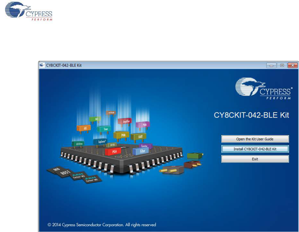
Software Installation
3. Click Install CY8CKIT-042-BLE Kit to start the kit installation, as shown in Figure 2-1.
Figure 2-1. Kit Installer Screen
4. Select the folder in which you want to install the CY8CKIT-042-BLE kit-related files. Choose the
directory and click Next.
5. When you click Next, the CY8CKIT-042-BLE Kit installer automatically installs the required
software, if it is not present on your computer. The following software packages are required:
Note: For the Setup Only installer package, download and install the following prerequisites.
a. PSoC Creator 3.1 or later: Download the latest version from www.cypress.com/psoccreator.
b. PSoC Programmer 3.21.1 or later: This is installed as part of PSoC Creator installation
(www.cypress.com/programmer).
c. CySmart 1.0 or later: Download the latest version from www.cypress.com/go/cysmart.
CY8CKIT-042-BLE Bluetooth® Low Energy (BLE) Pioneer Kit Guide, Doc. # 001-93731 Rev. *A 22
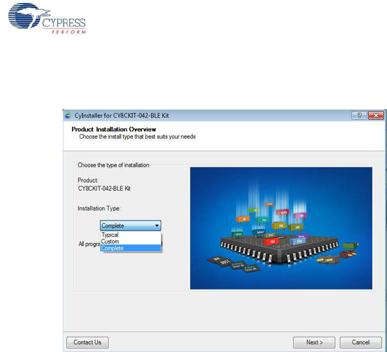
Software Installation
6. Choose the Typical/Custom/Complete installation type in the Product Installation Overview
window, as shown in Figure 2-2. Click Next after you select the installation type.
Figure 2-2. Product Installation Overview
7. Read the license agreement and select I accept the terms in the license agreement to
continue with installation. Click Next.
8. When the installation begins, a list of packages appears on the installation page. A green check
mark appears next to each package after successful installation.
9. Click Finish to complete the CY8CKIT-042-BLE kit installation.
10.Enter your contact information or select the Continue Without Contact Information check box.
Click Finish to complete the CY8CKIT-042-BLE kit installation.
11.After the installation is complete, the kit contents are available at the following location:
<Install_Directory>\CY8CKIT-042-BLE Kit
Default location:
Windows 7 (64-bit): C:\Program Files (x86)\Cypress\CY8CKIT-042-BLE Kit
Windows 7 (32-bit): C:\Program Files\Cypress\CY8CKIT-042-BLE Kit
Note: For Windows 7/8/8.1 users, the installed files and the folder are read only. To use the installer
example project, follow the steps outlined in the Example Projects chapter on page 42.
The kit installer also installs the CySmart PC tool for PC. This software, along with the dongle, allows
the PC to emulate as a BLE Central device. Refer to CySmart PC Tool on page 160 for more details
on how to use the CySmart PC tool.

CY8CKIT-042-BLE Bluetooth® Low Energy (BLE) Pioneer Kit Guide, Doc. # 001-93731 Rev. *A 23
Software Installation
2.3 Uninstall Software
The software can be uninstalled using one of the following methods:
■Go to Start > All Programs > Cypress > Cypress Update Manager > Cypress Update
Manager; select the Uninstall button.
■Go to Start > Control Panel > Programs and Features for Windows 7 or Add/Remove
Programs for Windows XP; select the Uninstall/Change button.
CY8CKIT-042-BLE Bluetooth® Low Energy (BLE) Pioneer Kit Guide, Doc. # 001-93731 Rev. *A 24
3. Kit Operation
This chapter introduces you to the BLE Pioneer kit and the features that will be used as part of the kit
operation. We will discuss features such as USB connection, programming/debugging, and
programmer firmware update. The chapter also describes the USB-UART and USB-I2C bridges
along with the PC tools that can be used to communicate with the BLE device on the kit.
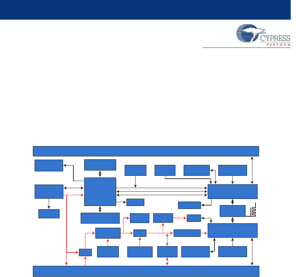
3.1 Theory of Operation
Figure 3-1, Figure 3-2, and Figure 3-3 show the block diagrams for the BLE Pioneer baseboard, BLE
module board, and BLE dongle.
Figure 3-1. BLE Pioneer Baseboard Block Diagram
The BLE Pioneer board acts as the baseboard for the PSoC 4 BLE (red module) and PRoC BLE
(black module). The Pioneer board contains a PSoC 5LP that is used as an onboard programmer or
debugger, and for the USB-Serial interface.
The baseboard is Arduino form-factor compatible, enabling Arduino shields to be connected on top
of the board to extend the functionality of BLE modules. The board also features a 1-Mb F-RAM, an
RGB LED, a five-segment CapSense slider, a proximity header, a user switch, and a reset switch for
the PSoC 4 BLE and PRoC BLE devices on the module. The Pioneer board supports three voltage
levels: 1.9 V, 3.3 V, and 5 V.
The baseboard can also be used as a standalone programmer to program and debug other PSoC 4
BLE/PRoC BLE devices using serial wire debug (SWD), and as a USB-Serial bridge. The firmware
on PSoC 5LP device enables bootloading PSoC 5LP over USB to upgrade the firmware.
Status LED
Green
BLE/Arduino Compatible Headers
Proximity wire
connector
CapSense Slider
5 Segment
Reset SW
(Push Button)
USB
Mini B PSoC 5LP
Programmer/Serial
Communication
PSoC 5LP
10 pin Prog. header
PSoC 5LP I/Os
16 pin Expansion header
PMOD header
6 pin PMOD header
ESD
Protection
MOSFET
Protection ckt
LDO ORing
Diodes
BLE/Arduino Compatible Headers
Jumper
BLE current measuring
Coin cell
Battery holder
Power
LED Red
BLE Module I/Os
20 pin header
FRAM
I2C pull-up
via FET
ORing
Diodes
User SW
(Push Button)
BLE Module I/Os
24 pin header
VIN
VBUS
VCC
D+ / D-
VDD
BLE Reset
3.3V
~3V
SWD
I2C / SPI / UART
I2C
Voltage Ctrl
3 pin Jumper
RGB LED
MOSFET
Protection ckt
BLE SWD
10 pin Prog. header
PRoC BLE/
PSoC 4 BLE
CY8CKIT-042-BLE Bluetooth® Low Energy (BLE) Pioneer Kit Guide, Doc. # 001-93731 Rev. *A 25
Kit Operation
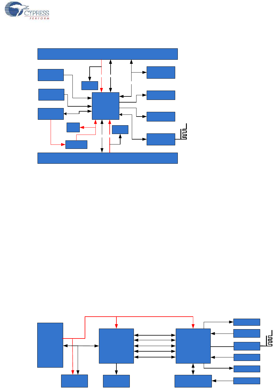
Figure 3-2. BLE Module Block Diagram
This kit includes two modules boards. These boards act as a basic breakout board for the
CY8C4247LQI-BL483 and CYBL10563-56LQXI BLE silicon. The PSoC 4 BLE and PRoC BLE
Modules are identical except for the silicon. In addition to including the PSoC 4 BLE and PRoC BLE
devices, the module boards also contain the BLE passives (resistors, capacitors, external crystals,
and antenna-matching network), an onboard antenna, and headers for connecting to the baseboard.
The BLE dongle is the host's wireless interface for the BLE device or project on the baseboard. The
dongle has a PRoC BLE device, to allow BLE connection with other kits. It also contains a
PSoC 5LP, to be used as an onboard programmer or debugger, and for the USB-Serial interface, as
shown in Figure 3-3.
The dongle has a USB A-type plug to connect the PSoC 5LP to the USB port of the host PC. The
PSoC 5LP then communicates with the PRoC BLE device over UART or multiplexed I2C or an SPI
bus. The board also features a user LED, a user switch, and a reset switch for the PRoC BLE
device. The dongle is powered directly through the USB port (VBUS) at 5.0 V.
The BLE dongle can also be used as a standalone programmer to program and debug other PSoC
devices (outside the dongle board) using SWD, and as a USB-Serial bridge after removing the
resistor between the SWD pins of PSoC 5LP and PRoC BLE.
Figure 3-3. BLE Dongle Block Diagram
PRoC BLE/
PSoC 4
BLE
BLE I/Os
20 pin Header (Digital, Power and Ground Pins)
GPIO
GPIO
KHz
Crystal
Decaps
CMOD
SAR
Bypass Cap
CTANK
VREF
Power
RF
matching
MHz
Crystal
Test
points
4 pin
header RX/ TX/ Gnd
BLE I/Os
24 pin Header (Analog, Power and Ground Pins)
Ferrite Bead
VDDD/A/R
Power Power
Decaps
MATCHING
CIRCUIT
PSoC 5LP
68QFN
I2C
UART
SWD
SPI
USB
2.0
Type-A
Plug
10-Pin Programming
Header
SWD
USER Button
USER LED
XRES Button
XRES
RF
Test Points
Protection
Circuits
D+ / D-
STATUS LED
POWER LED
EXTRA GPIO
CRYSTALS
PRoC BLE
56QFN
Power
CY8CKIT-042-BLE Bluetooth® Low Energy (BLE) Pioneer Kit Guide, Doc. # 001-93731 Rev. *A 26
Kit Operation
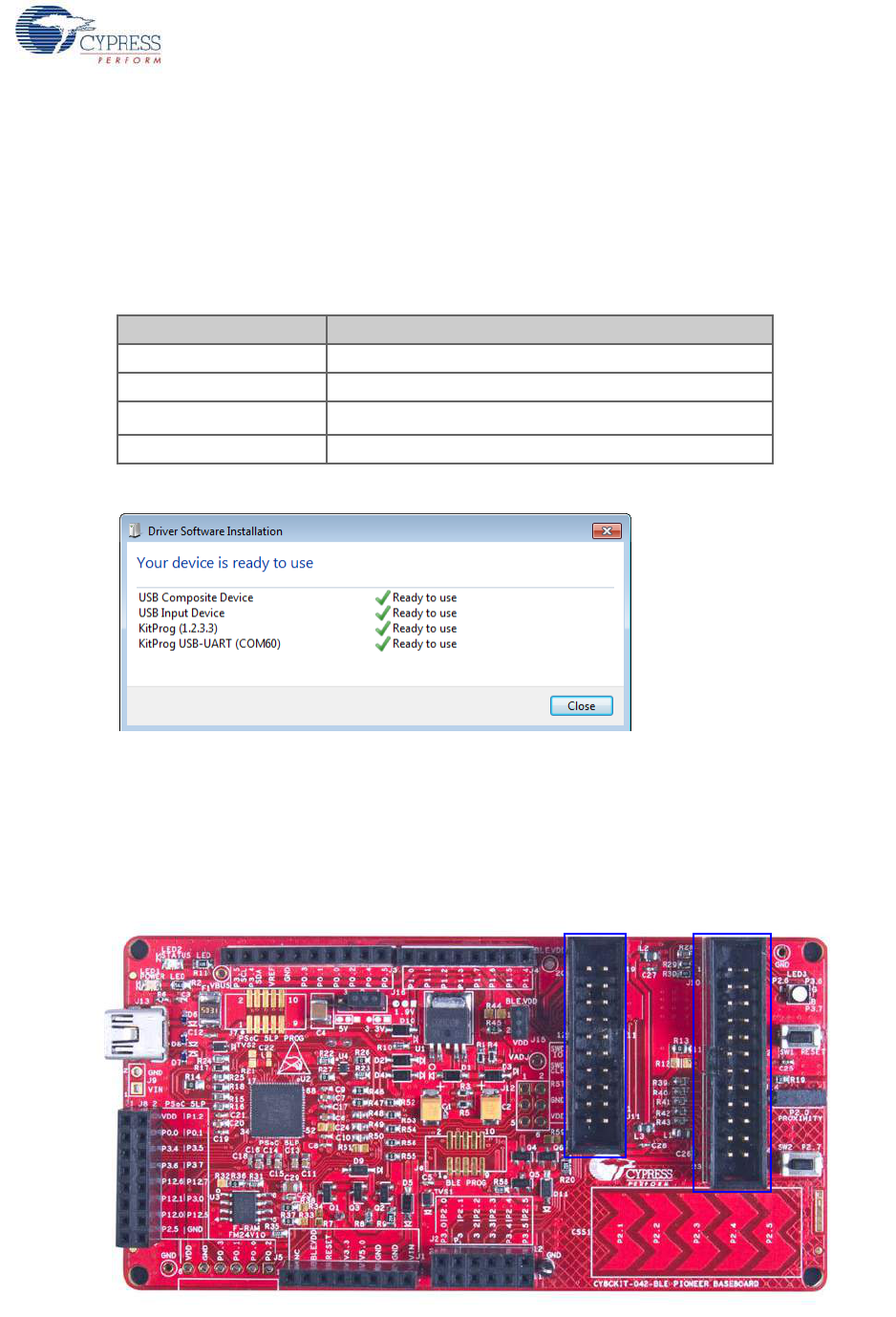
3.2 BLE Pioneer Kit USB Connection
The BLE Pioneer kit connects to and powers from a PC over the USB interface (J13). The kit enu-
merates as a composite device, as shown in Table 3-1.
Note: Ensure that you install the kit installer on the system for successful enumeration. To download
and install the BLE Pioneer Kit, visit www.cypress.com/go/CY8CKIT-042-BLE.
Figure 3-4. KitProg Driver Installation (appearance may differ depending on Windows platform)
3.3 Placing Modules on Baseboard
Plug the BLE module into the baseboard on headers J10 and J11, while keeping the antenna
directed outside of the baseboard. Note that the two parallel headers J10 and J11 are not equal
(24-pin and 20-pin, respectively) and will not allow the BLE module to be inserted in the opposite
direction.
Figure 3-5. Baseboard with J10 and J11 Headers to Connect BLE Modules
Table 3-1. BLE Pioneer Kit Enumerated Interfaces
Port Description
USB Composite Device Composite device
USB Input Device Programmer and debugger
KitProg USB-I2C bridge, programmer
KitProg USB-UART USB-UART bridge, which appears as a COM# port
CY8CKIT-042-BLE Bluetooth® Low Energy (BLE) Pioneer Kit Guide, Doc. # 001-93731 Rev. *A 27
Kit Operation
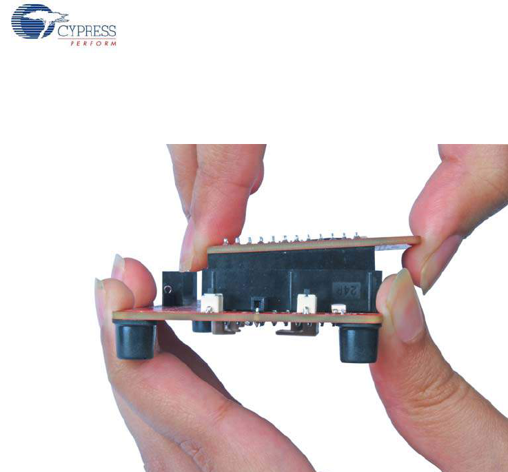
To remove the BLE modules from the BLE Pioneer kit, hold the BLE Pioneer kit in one hand and the
BLE module in the other, as shown in Figure 3-6, and pull it out using a rocking motion.
Figure 3-6. Remove BLE Module Connected on BLE Pioneer Kit
3.4 Programming and Debugging BLE Device
The BLE Pioneer kit and BLE dongle can be programmed and debugged using the onboard
PSoC 5LP programmer and debugger. Before programming the device, ensure that PSoC Creator
and PSoC Programmer are installed on the PC. See the section Install Software on page 20 for
more information.
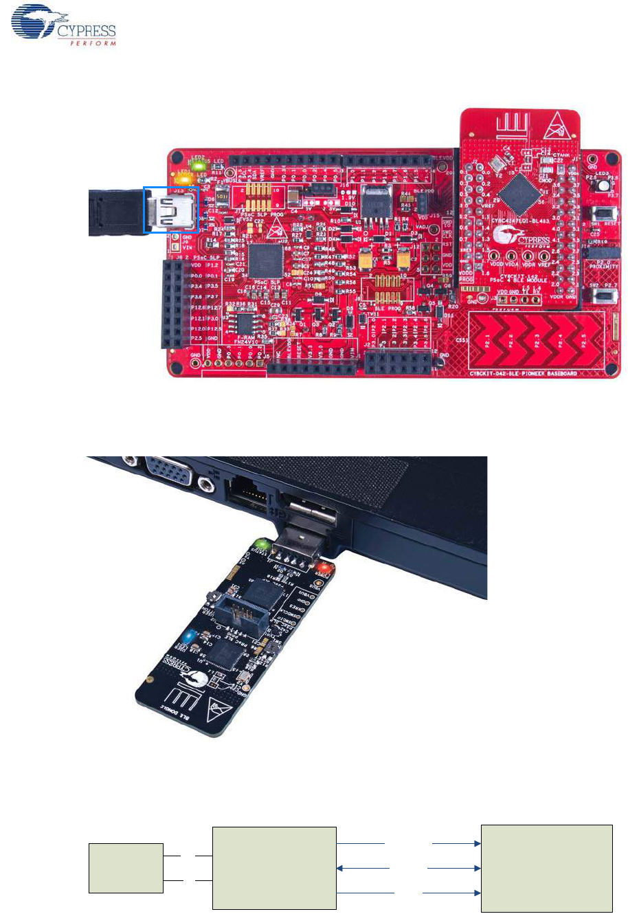
3.4.1 Programming and Debugging using PSoC Creator
1. To program the BLE Pioneer kit, plug the USB cable into the programming USB connector, J13,
and connect it to the USB port on the PC, as shown in Figure 3-7. The kit will enumerate as a
composite device.
CY8CKIT-042-BLE Bluetooth® Low Energy (BLE) Pioneer Kit Guide, Doc. # 001-93731 Rev. *A 28
Kit Operation
Figure 3-7. Connect USB Cable to J13
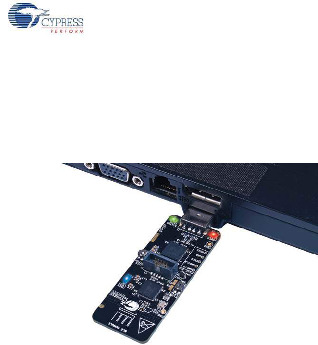
2. To program the BLE dongle, plug the dongle into the USB port of the PC, as shown in Figure 3-8.
The dongle will enumerate as a composite device.
Figure 3-8. Connect BLE Dongle to PC
3. The onboard PSoC 5LP uses SWD to program the PSoC 4 BLE or PRoC BLE device. See
Figure 3-9 for this implementation.
Figure 3-9. SWD Programming PSoC 4 BLE/PRoC BLE using PSoC 5LP
Mini USB PSoC 5LP PSoC 4 BLE/
PRoC BLE
SWDCLK
Reset
SWDIO
D+
D-
CY8CKIT-042-BLE Bluetooth® Low Energy (BLE) Pioneer Kit Guide, Doc. # 001-93731 Rev. *A 29
Kit Operation
4. To load the desired example project, open PSoC Creator and go to File > Open > Project/
Workspace. This will provide the option to browse to and open your saved project.
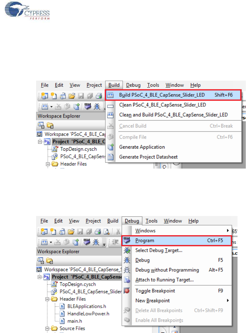
5. Build the project by choosing Build > Build <Project Name> or [Shift] [F6], as shown in
Figure 3-10.
Figure 3-10. Build an Example Project
6. If there are no errors during build, program the firmware into the kit by choosing Debug >
Program or pressing [Ctrl] [F5], as shown in Figure 3-11. This will program the device on the
BLE Pioneer Kit/BLE dongle and it will be ready for use. If debugging is needed on the project, go
to step 6.
Figure 3-11. Programming Device From PSoC Creator
7. To debug the project using PSoC Creator, choose Debug > Debug or press [F5].
8. When the project is built and programmed into the device on the BLE Pioneer kit/BLE dongle,
PSoC Creator will enter the Debug mode; you can use it to debug your application. For more
details on using the debug features, see the Cypress application note Getting Started with PSoC
4 BLE.
CY8CKIT-042-BLE Bluetooth® Low Energy (BLE) Pioneer Kit Guide, Doc. # 001-93731 Rev. *A 30
Kit Operation
3.4.2 Programming using PSoC Programmer
PSoC Programmer (3.21 or later) can be used to program existing hex files into the BLE Pioneer kit
or BLE dongle. To do this, follow these steps.
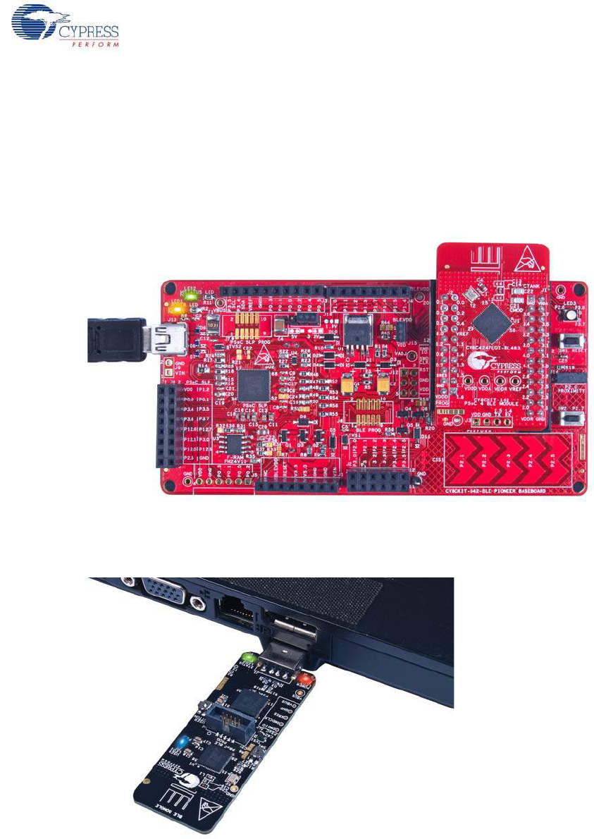
1. To program the BLE Pioneer kit, plug the USB cable into the programming USB connector, J13,
and connect it to the PC USB port, as shown in Figure 3-7. The kit will enumerate as a composite
device.
Figure 3-12. Connect BLE Pioneer Kit to PC
2. To program the BLE dongle, plug the dongle to the USB port of the PC, as shown in Figure 3-13.
The kit will enumerate as a composite device.
Figure 3-13. Connect BLE Dongle to PC
3. Go to Start > All Programs > Cypress > PSoC Programmer <version> > PSoC Programmer
<version>. The PSoC Programmer window will open as shown in Figure 3-13.
Note: BLE projects support PSoC Programmer 3.21 or later.
CY8CKIT-042-BLE Bluetooth® Low Energy (BLE) Pioneer Kit Guide, Doc. # 001-93731 Rev. *A 31
Kit Operation
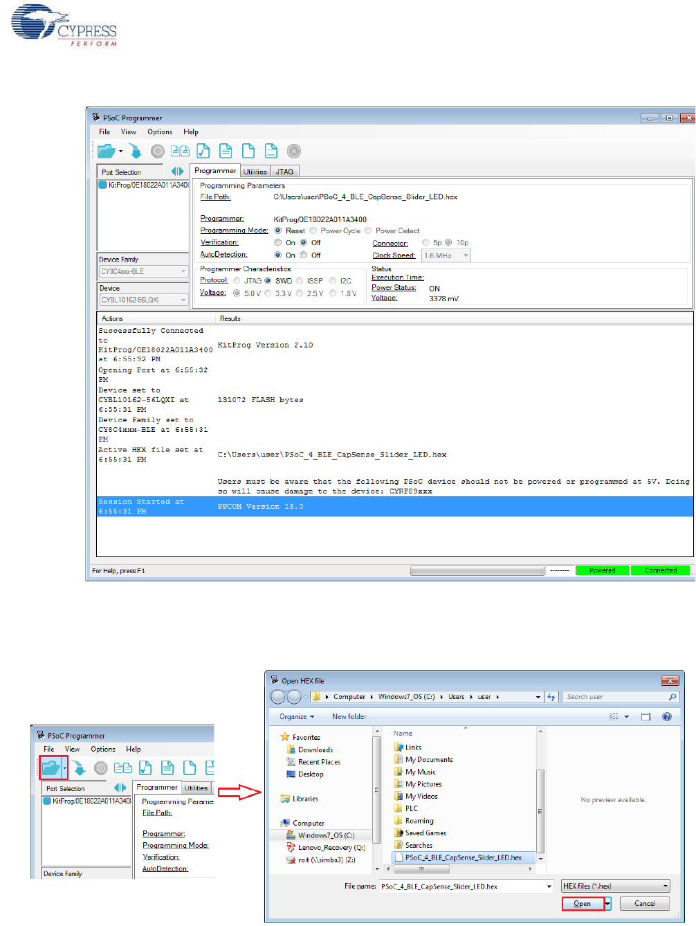
Figure 3-14. PSoC Programmenr GUI
4. Click the File Load button at the top left corner of the window. Browse for the desired hex file and
click Open.
Figure 3-15. Select Hex File
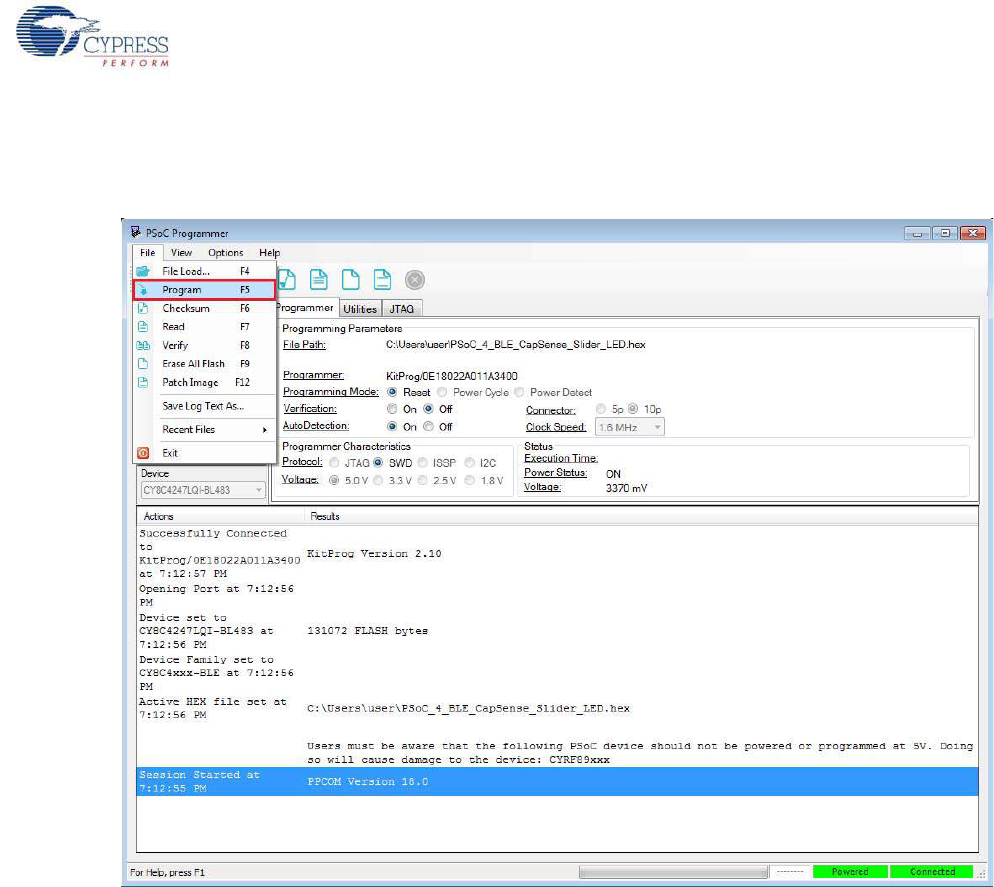
5. Go to File > Program to start programing the kit with the selected file.
CY8CKIT-042-BLE Bluetooth® Low Energy (BLE) Pioneer Kit Guide, Doc. # 001-93731 Rev. *A 32
Kit Operation
Note: If the hex file for a device is selected and programmed on the kit with a different device,
then PSoC Programmer will throw an error of device mismatch and terminate programming.
Figure 3-16. Program Hex File to Kit
6. When the programming is finished successfully, indicated by a PASS message on the status bar,
the kit is ready for use. Close PSoC Programmer.
CY8CKIT-042-BLE Bluetooth® Low Energy (BLE) Pioneer Kit Guide, Doc. # 001-93731 Rev. *A 33
Kit Operation
3.5 Updating BLE Dongle for CySmart PC Tool
The dongle, shown in Figure 3-17, provides a BLE Central mode capability using the CySmart PC
tool (see CySmart PC Tool on page 160) on the PC. The CySmart PC tool is used to connect and
validate the example projects loaded on the BLE Pioneer Kit (baseboard with one of the modules)
through BLE. The CySmart PC tool on the PC is the interface with which to configure the dongle and
analyze the BLE data transferred after connecting with a BLE peripheral.
Figure 3-17. Dongle
After being connected to the PC through the USB port, the dongle enumerates as a composite
device, similar to the BLE Pioneer kit. When enumerated, it allows similar features, such as
programming/debugging of the onboard PRoC BLE, USB-UART bridge, and USB-I2C bridge.
Additionally, the interface is used to communicate with the CySmart PC tool and emulate a BLE
Central device on PRoC BLE.
CY8CKIT-042-BLE Bluetooth® Low Energy (BLE) Pioneer Kit Guide, Doc. # 001-93731 Rev. *A 34
Kit Operation
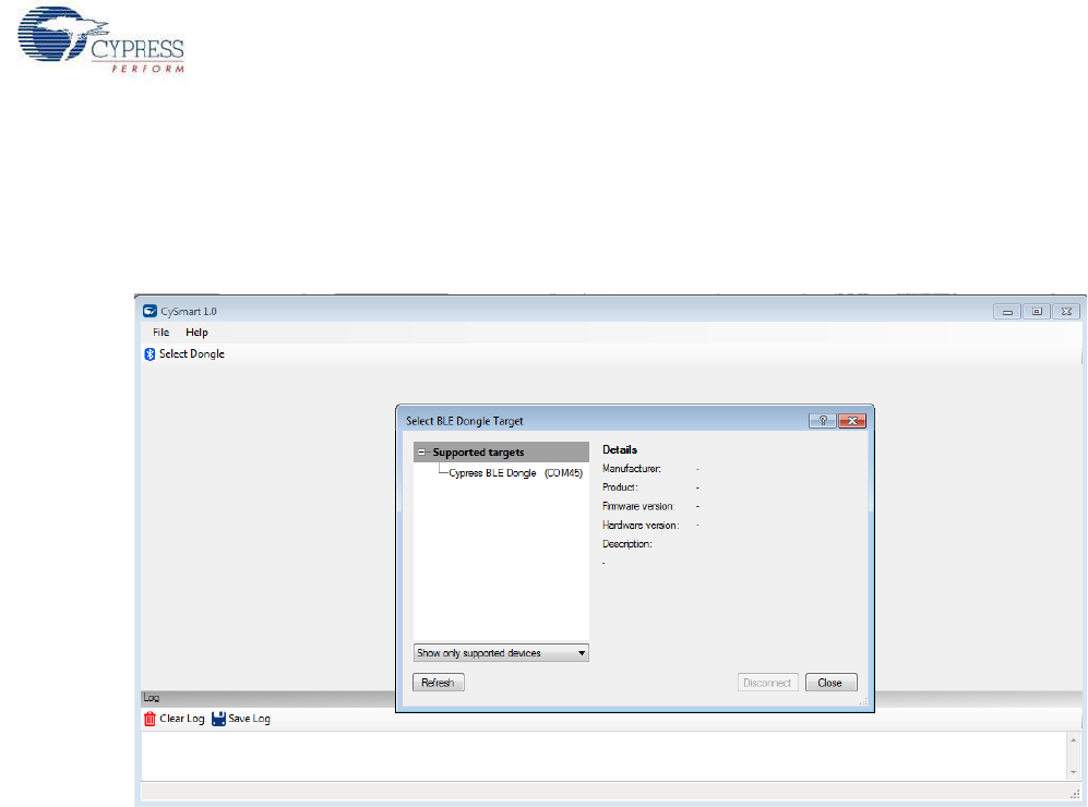
The dongle works along with the CySmart PC tool, as shown in Figure 3-18. The CySmart PC tool is
installed as part of the BLE Pioneer Kit installation and can be opened from Start > All Programs >
Cypress > CySmart <version> > CySmart <version>. The tool operation is explained in CySmart
PC Tool on page 160.
Figure 3-18. Dongle Interface on CySmart PC Tool
If the dongle contains custom firmware on PRoC BLE, the original CySmart firmware can be
programmed back to restore the CySmart functionality. It is not required to use the 10-pin
programming header on the dongle for this purpose. The dongle must be connected through the
USB and enumerated as KitProg. To do this, follow these steps:
1. Connect the dongle to the USB port on the PC.
2. Open PSoC Programmer by going to Start > All Programs > Cypress > PSoC Programmer
<version> > PSoC Programmer <version>.
3. When PSoC Programmer opens, it will automatically detect the KitProg on the dongle. Note that
every BLE dongle KitProg ID will start with the string 'BLE'. Click the File Load button and
browse to the location of the BLE_Dongle_CySmart.hex file. The hex file is located at:
C:\Program Files (x86)\Cypress\CY8CKIT-042-BLE Kit\<version>\Firmware\
BLE Dongle\Hex Files\
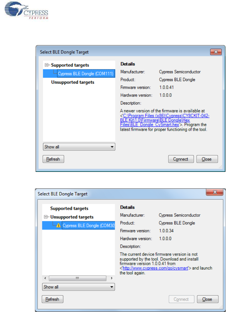
Note: If Cypress releases new versions of the CySmart PC tool and the BLE dongle firmware,
then the CySmart PC tool will display a message requesting to update the firmware on the BLE
dongle, as shown in the following figures.
CY8CKIT-042-BLE Bluetooth® Low Energy (BLE) Pioneer Kit Guide, Doc. # 001-93731 Rev. *A 35
Kit Operation
Figure 3-19. Update Dongle Firmware with Hex from Latest Kit Installer
Figure 3-20. Update Dongle Firmware with Hex from Web
In this scenario, choose the hex file from the respective location and update the dongle firmware with
the following steps.
CY8CKIT-042-BLE Bluetooth® Low Energy (BLE) Pioneer Kit Guide, Doc. # 001-93731 Rev. *A 36
Kit Operation
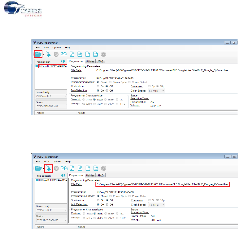
Figure 3-21. Open Hex File
4. Ensure the other settings match as shown in Figure 3-21. Click the Program button to start
programming. The status bar at the bottom of the PSoC Programmer window will show the
programming status and the result (Pass/Fail).
Figure 3-22. Programming Hex File to Dongle
5. After programming is completed successfully, the dongle firmware is updated and can be used to
connect to the CySmart PC tool.
3.6 USB-UART Bridge
The onboard PSoC 5LP on both the baseboard and dongle acts as a USB-UART bridge to transfer
and receive data from the PSoC 4 BLE or PRoC BLE device to the PC via the COM terminal
software. When the USB mini-B cable is connected to J13 of the baseboard or the dongle is
connected to the PC, a device named “KitProg USB-UART” is available under Ports (COM & LPT)
in the Device Manager. To use this functionality, a project supporting UART communication must be
created on the BLE device. More details are available in the section Using PSoC 5LP as USB-UART
Bridge on page 115.
For both the baseboard and the dongle, the UART lines are hardwired onboard between the PSoC
5LP and BLE Modules. No external UART connection between the two devices is needed. Simply
CY8CKIT-042-BLE Bluetooth® Low Energy (BLE) Pioneer Kit Guide, Doc. # 001-93731 Rev. *A 37
Kit Operation
place the UART component in the PSoC 4 BLE or PRoC BLE and assign the UART pins as shown in
Table 3-2.
Table 3-3 lists the specifications supported by the USB-UART bridge.
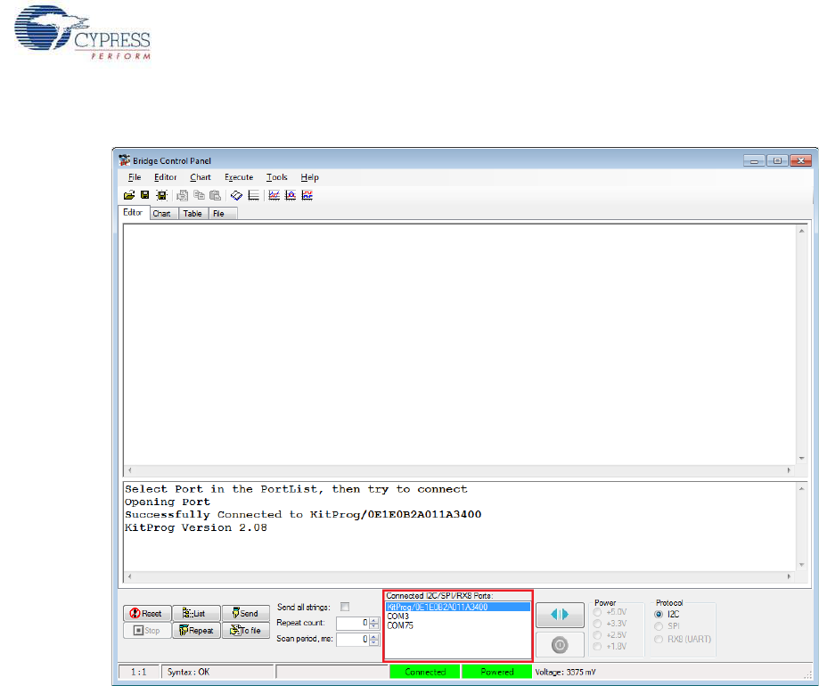
3.7 USB-I2C Bridge
The PSoC 5LP also functions as a USB-I2C bridge. In this role, PSoC 5LP communicates with
PSoC 4 BLE/PRoC BLE using an I2C interface, and sends that data over the USB to the USB-I2C
software utility running on the PC, called the Bridge Control Panel (BCP). This feature is available
for both the BLE Pioneer Kit and the BLE dongle.
The BCP is available as part of the PSoC Programmer installation. This software can be used to
send and receive USB-I2C data from the PSoC 5LP. When the USB mini-B cable is connected to
header J13 on the BLE Pioneer Kit or when the dongle is connected to the PC, the KitProg USB-I2C
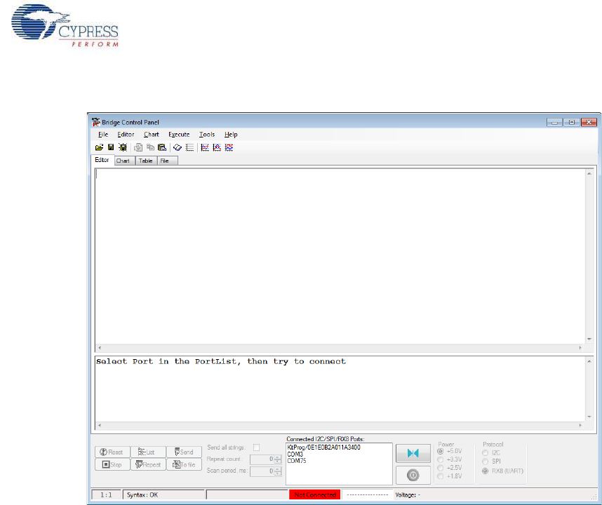
is available under Connected I2C/SPI/RX8 Ports in the BCP, as shown in Figure 3-23.
To open BCP in your system, go to Start > All Programs > Cypress > Bridge Control Panel.
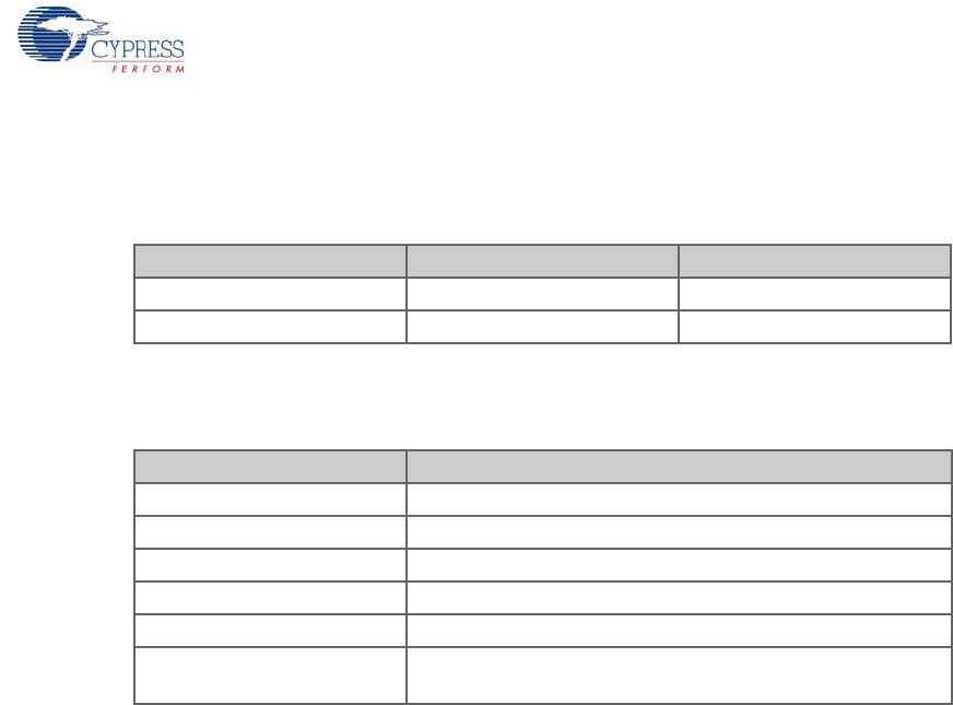
Table 3-2. UART Pin Assignment in BLE Devices for USB-UART Bridge
Pin BLE Pioneer Kit BLE Dongle
UART_RX P1_4 P1_4
UART_TX P1_5 P1_5
Table 3-3. Specifications Supported by USB-UART Bridge
Parameter Supported Values
Baud Rate 1200, 2400, 4800, 9600, 19200, 38400, 57600, and 115200
Data Bits 8
Parity None
Stop Bits 1
Flow Control None
File Transfer Protocols sup-
ported Xmodem, 1K Xmodem, Ymodem, Kermit, and Zmodem (only
speeds greater than 2400 baud)
CY8CKIT-042-BLE Bluetooth® Low Energy (BLE) Pioneer Kit Guide, Doc. # 001-93731 Rev. *A 38
Kit Operation
Figure 3-23. Bridge Control Panel
To use the USB-I2C functionality, select the KitProg USB-I2C in the BCP. On successful connection,
the Connected and Powered tabs turn green, as shown in Figure 3-24.
CY8CKIT-042-BLE Bluetooth® Low Energy (BLE) Pioneer Kit Guide, Doc. # 001-93731 Rev. *A 39
Kit Operation
Figure 3-24. KitProg USB-I2C Connected in Bridge Control Panel
USB-I2C is implemented using the USB and I2C components of PSoC 5LP. For the BLE Pioneer Kit,
the SCL (P12_0) and SDA (P12_1) lines from the PSoC 5LP are connected to the SCL (P3_5) and
SDA (P3_4) lines of the BLE module header. For the dongle, the SCL (P12_0) and SDA (P12_1)
lines from the PSoC 5LP are connected to the SCL (P3_5) and SDA (P3_4) lines. The USB-I2C
bridge currently supports I2C speed of 50 kHz, 100 kHz, 400 kHz, and 1 MHz.
See Using PSoC 5LP as USB-I2C Bridge on page 126 to build a project that uses the USB-I2C
bridge functionality.
CY8CKIT-042-BLE Bluetooth® Low Energy (BLE) Pioneer Kit Guide, Doc. # 001-93731 Rev. *A 40
Kit Operation
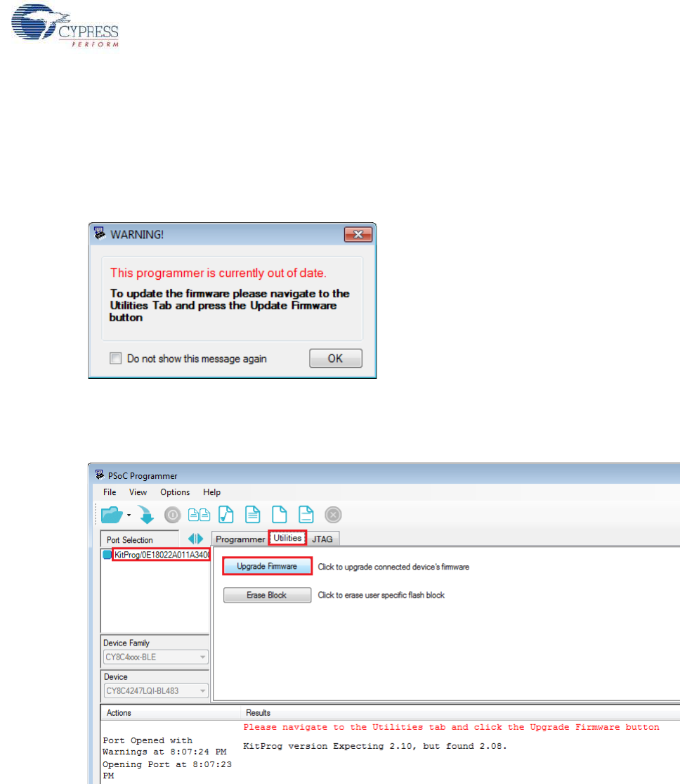
3.8 Updating the Onboard PSoC 5LP Programmer Firmware
The BLE Pioneer kit and BLE dongle contains the PSoC 5LP programmer (KitProg) required for pro-
gramming, debugging and communication over the COM port. The KitProg normally does not
require any update. If an update is required, then PSoC Programmer will display a warning message
when the kit or dongle is connected to it, as shown in Figure 3-25.
Figure 3-25. Update KitProg
To update the KitProg, go to the Utilities tab on PSoC Programmer and click Upgrade Firmware, as
shown in Figure 3-26.
Figure 3-26. Update KitProg from PSoC Programmer
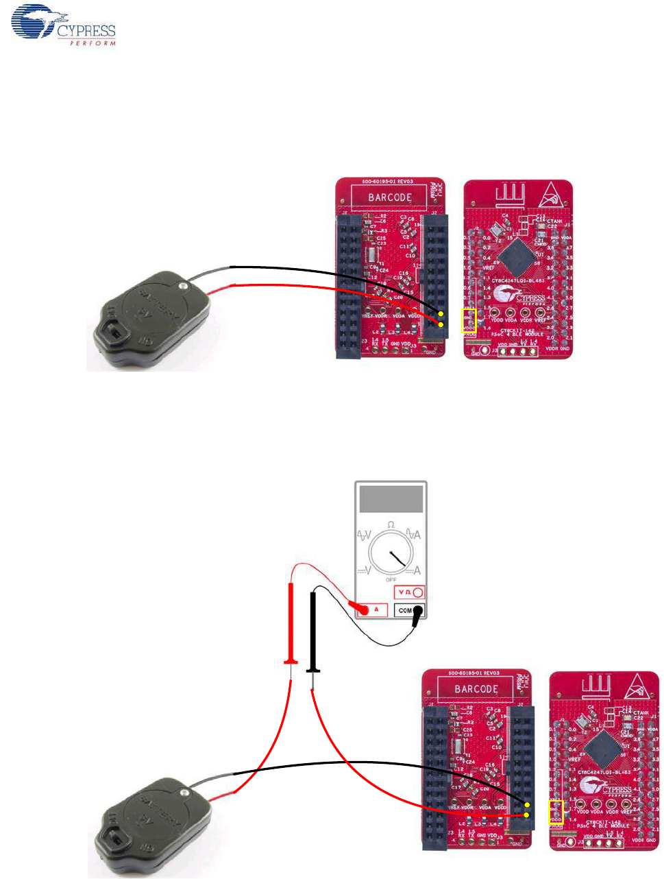
3.9 Measure Coin Cell Power Consumption
To measure the power consumption of a project with coin cell, connect the coin cell directly to the
BLE modules, as shown in Figure 3-27. The baseboard is designed with additional circuits to protect
the PSoC 4 BLE/PRoC BLE device and the F-RAM in Arduino environment. Note that power
consumption measurements on the baseboard will also include the power consumed by these
additional circuits.
After you have programmed your application on the CY8CKIT-142 PSoC 4 BLE Module or the
CY5671 PRoC BLE Module, remove the BLE module from the baseboard and connect the coin cell
(Figure 3-27). This setup enables an accurate power consumption measurement for the application.
CY8CKIT-042-BLE Bluetooth® Low Energy (BLE) Pioneer Kit Guide, Doc. # 001-93731 Rev. *A 41
Kit Operation
The other pins on the BLE module can be used to build the desired application.
Connect the positive terminal of the coin cell to pin J2.2 and negative terminal to pin J2.4 using
wires.
Figure 3-27. Powering the BLE Module using a Coin Cell
Connect an ammeter in series with the battery to measure the power consumption as shown in
Figure 3-28.
Figure 3-28. Current Measurement of BLE Module when Powered from a Coin Cell

CY8CKIT-042-BLE Bluetooth® Low Energy (BLE) Pioneer Kit Guide, Doc. # 001-93731 Rev. *A 42
4. Example Projects
This chapter demonstrates the functionality of the PSoC 4 BLE and PRoC BLE devices using the
BLE Pioneer kit-based example projects. To access these example projects, download and install
the kit setup file from the kit web page. The example projects are available in the firmware folder
under the installed directory.
The Cypress BLE device comes in two variants:
■PSoC 4 BLE: The PSoC 4 BLE product family is the new wireless member of the PSoC 4
architecture platform. The family provides a full programmable analog and digital system and a
complete schematic view of PSoC Creator. The PSoC 4 BLE family provides a 32-bit ARM
Cortex-M0 based MCU subsystem with programmable analog and digital peripherals, such as
universal digital blocks (UDBs), 12-bit SAR ADC, opamp, LP comparator, IDACs, UART, I2C, SPI,
and timer/counter/PWM block. It also has a dedicated CapSense block (in select part numbers)
to implement the touch-sensing solution, with a practical system SNR of 100:1.
■PRoC BLE: This family provides prebuilt part numbers for applications such as human interface
devices (HID), remote control, trackpad, and toys. PRoC BLE also supports up to two-finger
gestures for trackpad and remote control applications. The PRoC BLE product family enriches
the PRoC wireless capacitive touch devices with the Bluetooth Low Energy protocol. The PRoC
BLE family has embedded gestures (in select part numbers) to implement the touch-sensing
solution for trackpad implementation. It also provides a 32-bit ARM Cortex-M0 based MCU
subsystem with analog and digital peripherals, such as 12-bit SAR ADC, UART, I2C, PWMs, and
timer/counter/PWM blocks. The family uses a special PSoC Creator schematic view for easy
configuration of PRoC BLE devices.
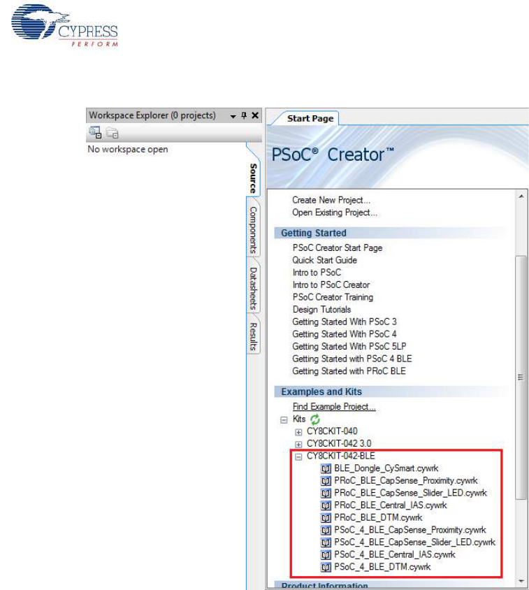
4.1 Using Example Projects
Follow these steps to open and use the example projects:
1. Launch PSoC Creator from Start > All Programs > Cypress > PSoC Creator 3.1 > PSoC
Creator 3.1.
2. On the Start Page, choose Examples and Kits > Kits > CY8CKIT-042-BLE. A list of example
projects appears, as shown in Figure 4-1. Projects named with the prefix 'PSoC_4_BLE_' work
on the BLE Pioneer kit with the PSoC 4 BLE Module; projects named with the prefix
'PRoC_BLE_' work on the BLE Pioneer kit with the PRoC BLE Module.
3. Click on the desired example project.
CY8CKIT-042-BLE Bluetooth® Low Energy (BLE) Pioneer Kit Guide, Doc. # 001-93731 Rev. *A 43
Example Projects
Figure 4-1. Open Example Project from PSoC Creator
4. Select the folder where you want to save the project and click OK.
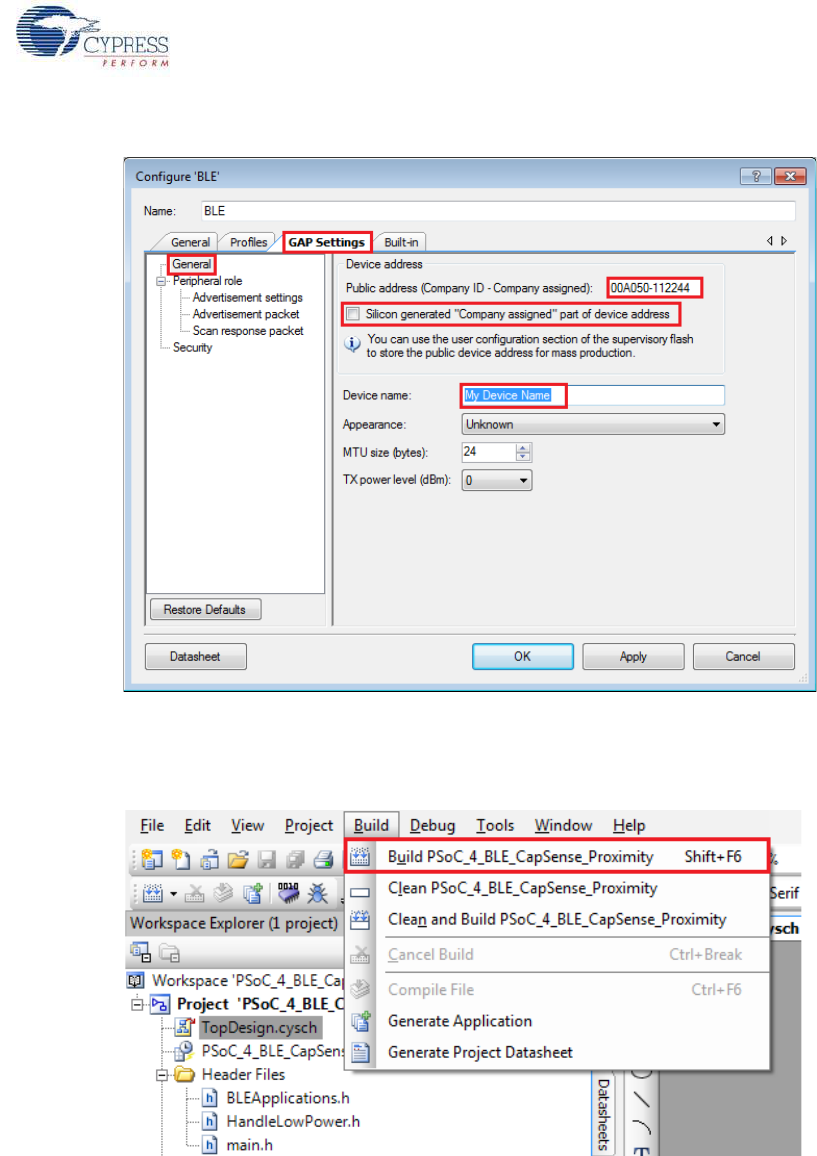
5. BLE projects use a public device address set in the BLE component GUI to advertise and scan,
depending on the role: peripheral or central mode. If there are other kits in close proximity, which
have the same public device address, then wrong devices may be connected or connections can
fail. To prevent this, you can change the Public device address (and preferably Device name)
in the BLE component. To do this, double-click the BLE component in TopDesign, go to the GAP
Settings tab, and choose the General setting. Add the desired public device address (non-zero)
and device name in the respective fields, as shown in Figure 4-2. Click OK.
Alternatively, you can select the 'Silicon generated' device address by selecting the check box.
This way, the BD address is generated using the silicon ID, unique to each silicon. Click OK.
CY8CKIT-042-BLE Bluetooth® Low Energy (BLE) Pioneer Kit Guide, Doc. # 001-93731 Rev. *A 44
Example Projects
Figure 4-2. Change BLE Public Device Address and Name
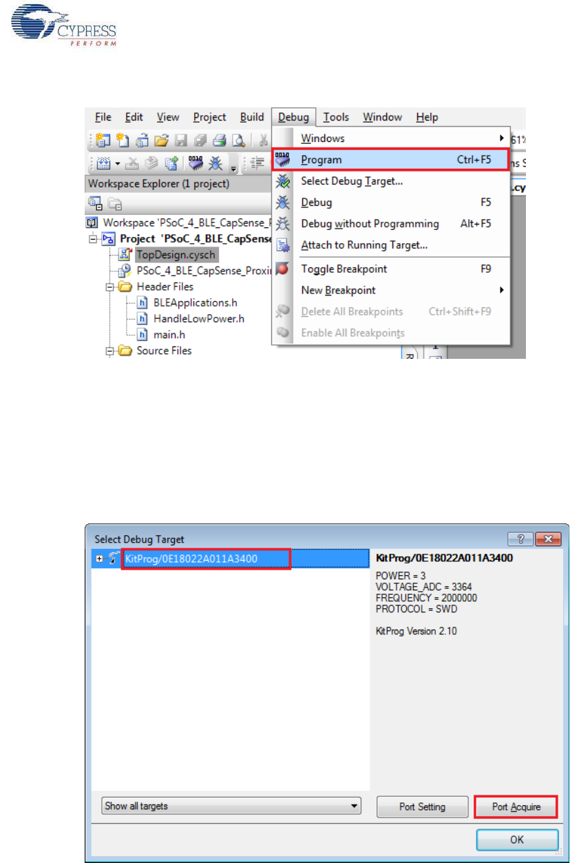
6. Build the example project by choosing Build > Build <Project Name>, as shown in Figure 4-3. A
hex file will be generated.
Figure 4-3. Build Project from PSoC Creator
7. To program the kit with this example project, connect the baseboard to the PC by plugging it into
the USB mini-B connector (J13) on the baseboard, as described in BLE Pioneer Kit USB
Connection on page 26. Ensure that the correct BLE Module (PSoC 4 BLE or PRoC BLE) is
placed on the baseboard, depending on the project opened.
8. Choose Debug > Program in PSoC Creator, as shown in Figure 4-4.
CY8CKIT-042-BLE Bluetooth® Low Energy (BLE) Pioneer Kit Guide, Doc. # 001-93731 Rev. *A 45
Example Projects
Figure 4-4. Program Device in PSoC Creator
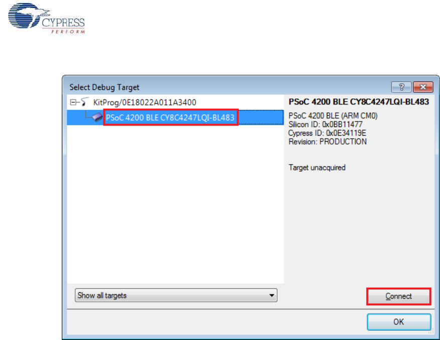
9. If the device is not yet acquired, PSoC Creator will open the programming window. Select
KitProg and click the Port Acquire button, as shown in Figure 4-5.
Note: The string following 'KitProg' is the serial ID for the programmer on the kit. Each kit will
have a unique serial ID. If various kits are connected to the same system, the serial ID can be
used to select the correct kit to program the firmware. Additionally, the serial ID starting with 'BLE'
belongs to the dongle (see Updating BLE Dongle for CySmart PC Tool on page 33) and provides
visual confirmation for dongles connected to the system.
Figure 4-5. Port Acquire
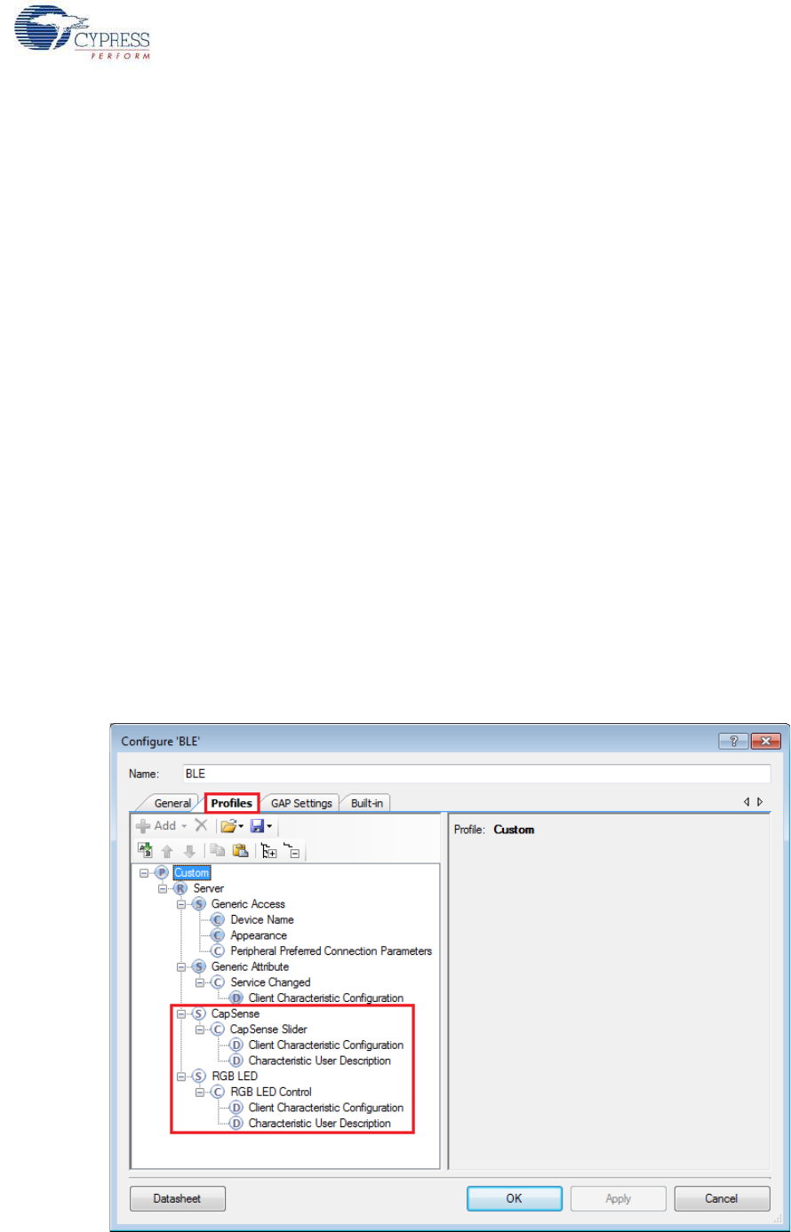
10.After the device is acquired, it is shown in a structure below the KitProg. Click the Connect but-
ton and then OK to exit the window and start programming, as shown in Figure 4-6.
CY8CKIT-042-BLE Bluetooth® Low Energy (BLE) Pioneer Kit Guide, Doc. # 001-93731 Rev. *A 46
Example Projects
Figure 4-6. Connect Device From PSoC Creator and Program
Note: As stated previously, the BLE Pioneer kit supports both Cypress BLE devices: PSoC 4 BLE
and PRoC BLE. Thus, there are two versions of each of the kit example projects demonstrating the
same functionality. Projects named with the prefix PSoC_4_BLE_ work with the PSoC 4 BLE Module
placed on the baseboard. Projects named with the prefix PRoC_BLE_ work with the PRoC BLE
Module placed on the baseboard. Ensure that the correct module is placed on the baseboard before
programming the device with the corresponding kit example projects.
The description, hardware configurations, and verification method of the kit example projects
explained in the following sections are valid for both PSoC 4 BLE and PRoC BLE devices. Unless
explicitly mentioned, the theory and usability for these example projects should be considered the
same for both the modules/devices.
This document refers to the BLE Pioneer kits, dongle, and PC/mobile as BLE Central or peripheral
devices. A BLE Central device is normally the master and requests/commands data from the
peripheral device. BLE-enabled phones and PCs are one such example. BLE peripheral devices, on
the other hand, store the actual data and send it to central devices when requested. Examples
include BLE-enabled sensors, proximity beacons, and so on.
CY8CKIT-042-BLE Bluetooth® Low Energy (BLE) Pioneer Kit Guide, Doc. # 001-93731 Rev. *A 47
Example Projects
4.2 CapSense Slider and LED
4.2.1 Project Description
This project demonstrates BLE connectivity between the BLE Pioneer kit (acting as a peripheral and
server device) and BLE dongle or mobile device running the CySmart application (acting as a central
and client device). This project demonstrates following:
■Advertisement with timeout
■Connection with any BLE Central device
■Two custom services in single profile
■Data transfer over BLE custom service using notifications, read, and write
■Low-power mode implementation for battery operation
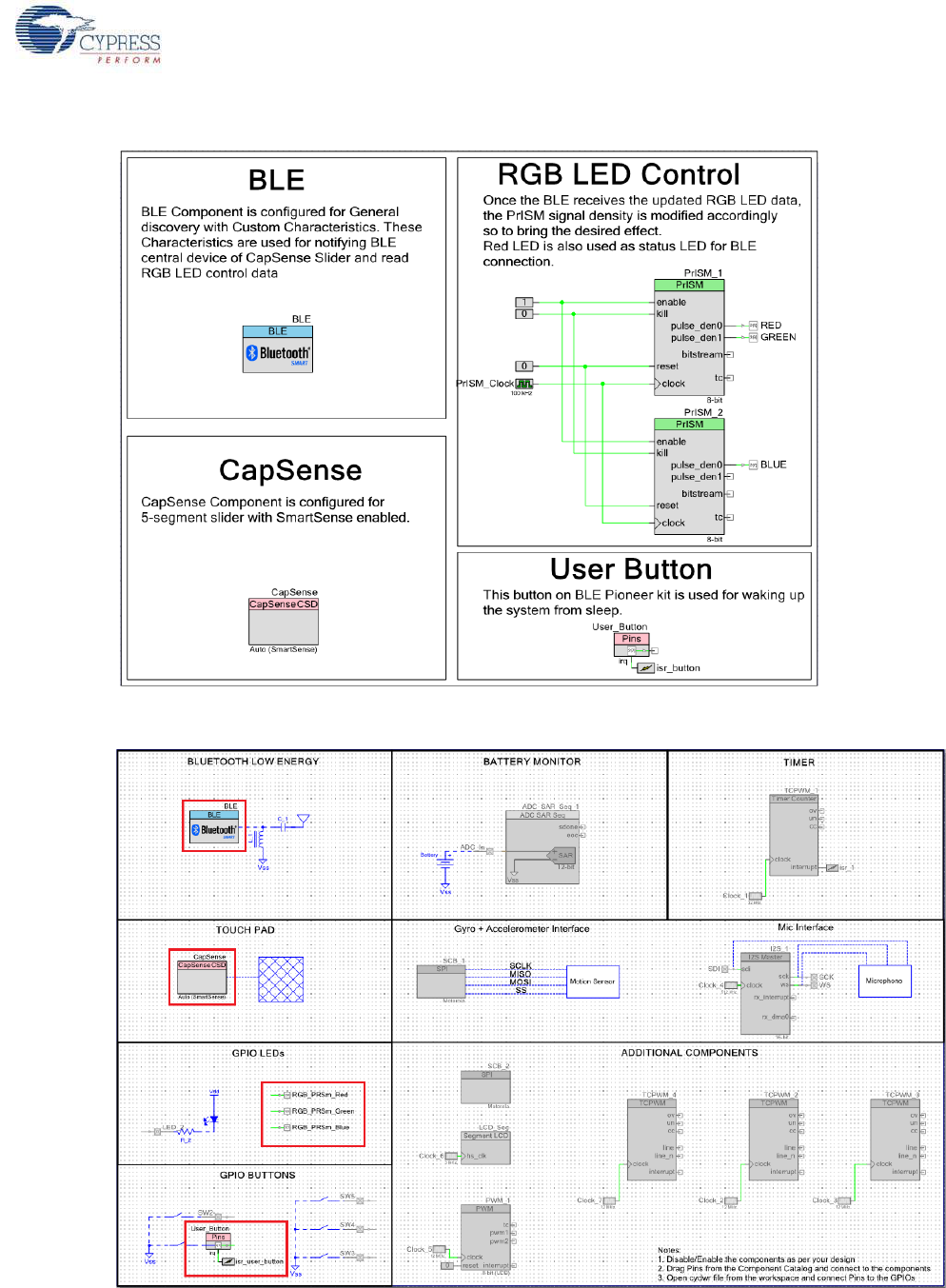
The BLE profile in this project consists of two BLE custom services: CapSense and RGB LED. The
CapSense service consists of one custom characteristic, termed as CapSense Slider. The
CapSense slider characteristic is used to send one byte data, ranging from 0 to 100, as notification
to the client device. This data is the finger location read by the CapSense component on the five-
segment slider (CSS1) present on the kit. This characteristics supports notification, which allows the
BLE server to send data to the connected client device whenever new data is available.
The RGB LED service also consists of one custom characteristic, termed as RGB LED Control.
This characteristic supports two operations, read and write, through which the connected client
device can read data as well as write a new value to the characteristic. This data has four byte val-
ues indicating red, green, blue, and intensity values for the onboard RGB LED.
These properties for the custom service/characteristics are configured in the BLE component under
the Profiles tab, as shown in Figure 4-7.
Figure 4-7. Attributes Configuration in BLE Component for Custom Services

CY8CKIT-042-BLE Bluetooth® Low Energy (BLE) Pioneer Kit Guide, Doc. # 001-93731 Rev. *A 48
Example Projects
The project consists of the following files:
■main.c/.h
These files contain the main function, which is the entry point and execution of the firmware appli-
cation. It also contains function definition for initialization of the system and reading the
CapSense slider data from the CapSense component.
■BLEApplications.c/.h
These files contain all the macros and function definitions related to BLE communication and
operation. It contains the event callback function definition that is registered with the BLE compo-
nent startup and used by the component to send BLE-related events from the BLE stack to the
application layer for processing. It contains a method to send CapSense notifications to the client
device and process the Read and Write commands on the RGB LED characteristic by the client
device. It updates the BLE Connection parameter, which is important for low-power mode usage.
■HandleLowPower.c/.h
These files contain the function to handle low-power mode. This function is continuously called in
the main loop and is responsible for pushing the BLE hardware block (BLESS) as well as the
CPU to Deep Sleep mode as much as possible. The wakeup source is either the BLE hardware
block Link Layer internal timer or the interrupt from the user button press (SW2). This allows for
very low power mode implementation and operation using a coin cell.
Additionally, the PRoC BLE version of this project consists of the RGB_PRSm.c/.h file, which con-
tains the function to drive the software-based PrISM method and drive the color and intensity on the
RGB LED.
This is the default firmware that comes in the BLE modules shipped with the kit.
Two projects demonstrate this functionality on two different devices:
■PSoC_4_BLE_CapSense_Slider_LED works with the PSoC 4 BLE Module
■PRoC_BLE_CapSense_Slider_LED works with the PRoC BLE Module.
The PSoC 4 BLE project implements RGB color and intensity control using the PRiSM component
whereas the PRoC BLE uses the software implementation of the PRiSM mode.
CY8CKIT-042-BLE Bluetooth® Low Energy (BLE) Pioneer Kit Guide, Doc. # 001-93731 Rev. *A 49
Example Projects
Figure 4-8. TopDesign for PSoC_4_BLE_CapSense_Slider_LED Project
Figure 4-9. TopDesign for PRoC_BLE_CapSense_Slider_LED Project
CY8CKIT-042-BLE Bluetooth® Low Energy (BLE) Pioneer Kit Guide, Doc. # 001-93731 Rev. *A 50
Example Projects
4.2.2 Hardware Connections
No specific hardware connections are required for this project because all connections are
hardwired on the board. Ensure that the correct BLE Module is placed on the baseboard
corresponding to the project being used. PSoC_4_BLE_CapSense_Slider_LED works with the
PSoC 4 BLE Module. PRoC_BLE_CapSense_Slider_LED works with the PRoC BLE Module.
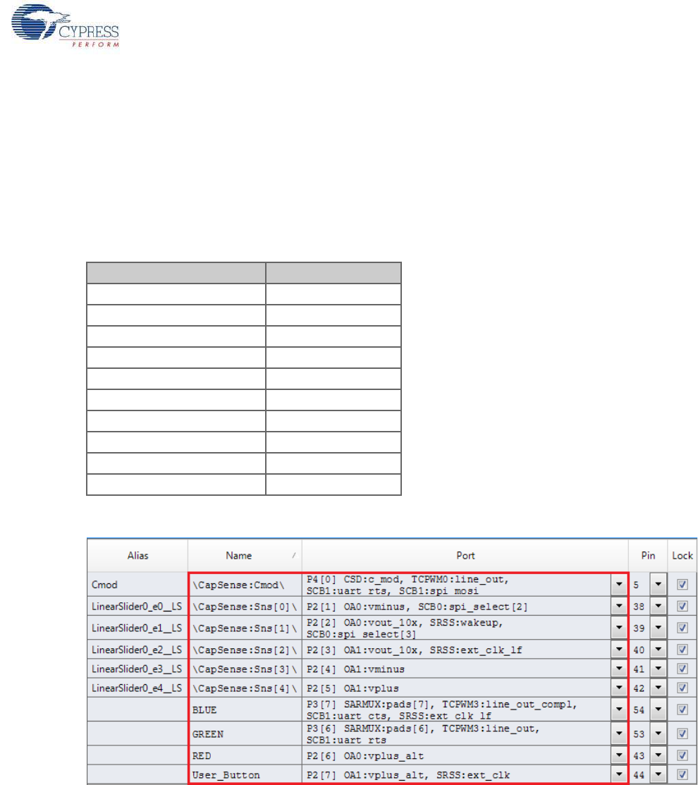
The pin assignment for this project is in PSoC_4_BLE_CapSense_Slider_LED.cydwr/
PRoC_BLE_CapSense_Slider_LED.cydwr in the Workspace Explorer, as shown in Figure 4-10.
Figure 4-10. Pin Selection for CapSense Slider and LED Project
Table 4-1. Pin Assignments for CapSense Slider and LED Project
Pin Name Port Name
CapSense CMOD P4_0
CapSense Slider 1 P2_1
CapSense Slider 2 P2_2
CapSense Slider 3 P2_3
CapSense Slider 4 P2_4
CapSense Slider 5 P2_5
BLUE P3_7
GREEN P3_6
RED P2_6
User_Button P2_7
CY8CKIT-042-BLE Bluetooth® Low Energy (BLE) Pioneer Kit Guide, Doc. # 001-93731 Rev. *A 51
Example Projects
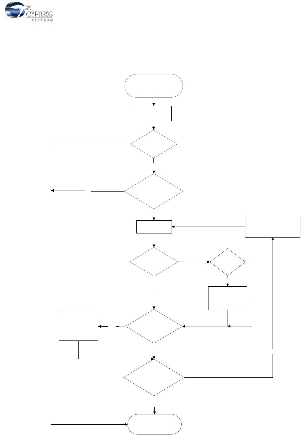
4.2.3 Flow Chart
Figure 4-11 shows the flow chart of the code implemented.
Figure 4-11. CapSense Slider and LED Project Flow Chart
Start
Advertisement
CapSense Slider
Swipped?
Received RGB
LED Data?
NO
BLE Connection
Still Present?
NO
Send finger position
over CapSense
custom service
YES
Extract Data and
change color/
brightness on LED.
Keep LED ON for
set time
YES
Connected to BLE
Central device before
timeout?
YES
NO
Notifications
Enabled?
YES
NO
System in Deep Sleep and
waiting for User button press
NO
Advertisement
Time-out?
NO
YES
Put system to low power
mode and wait for interrupt
from BLE Link Layer
YES
System initialized.
Wait for interrupt from User
Button to Wakeup
Process BLE
Events
CY8CKIT-042-BLE Bluetooth® Low Energy (BLE) Pioneer Kit Guide, Doc. # 001-93731 Rev. *A 52
Example Projects
4.2.4 Verify Output
The project can be verified by two methods: using the CySmart PC tool and dongle or using the
CySmart iOS/Android BLE app.
To install and use the CySmart PC tool, see CySmart PC Tool on page 160.
To install and use the CySmart iOS/Android app, see CySmart iOS/Android Application on page 152.
4.2.4.1 CySmart PC Tool
To verify the CapSense and LED project using the CySmart PC tool, follow these steps:
Note: See CySmart PC Tool on page 160 to learn how to use the tool.
1. Connect the dongle to one of the USB ports on the PC.
2. Start the CySmart PC tool on the PC by going to Start > All Programs > Cypress > CySmart
<version> > CySmart <version>. You will see a list of dongles connected to it. If no dongle is
found, click Refresh. Select the BLE dongle and click Connect.
Figure 4-12. Connect to BLE Dongle
3. Place either the PSoC 4 BLE Module or PRoC BLE Module, on the BLE Pioneer kit, depending
on the project chosen.
4. Power the BLE Pioneer kit through the USB connector J13.
5. Program the BLE Pioneer kit with the CapSense and LED example projects. Follow steps in
Using Example Projects on page 42 to program the device.
6. After programming successfully, press the user button (SW2) on the BLE Pioneer kit to start the
advertisement. Advertisement is indicated by a blinking red LED on the baseboard.
Note: The project has an advertisement timeout of 30 seconds. If the BLE client device does not
connect to this peripheral within 30 seconds of starting the advertisement, the system goes back
to low-power mode. Press SW2 again to restart the advertisement.
7. On the CySmart PC tool, click Start Scan to see the list of available BLE peripheral devices. You
can confirm your device by the device name and Bluetooth address on the list. This should be
same as the one configured in the BLE component GUI.
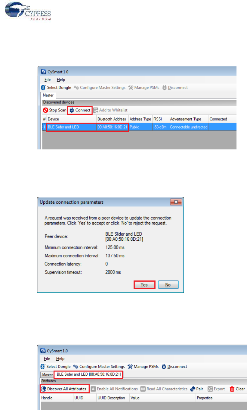
CY8CKIT-042-BLE Bluetooth® Low Energy (BLE) Pioneer Kit Guide, Doc. # 001-93731 Rev. *A 53
Example Projects
8. After the available devices are listed, double-click the BLE Slider and LED device to connect, or
click BLE Slider and LED and then click Connect.
Figure 4-13. Connect to BLE Slider and LED Peripheral
9. When the connection is made, the CySmart PC tool will display a message for the Update Con-
nection parameters. This is the request from the BLE peripheral to update the existing connec-
tion parameters, such as connection interval, latency, and supervision timeout, to a new value.
Select Yes, as shown in Figure 4-14.
Figure 4-14. Update Connection Parameter Option
Note: If you select No, the project will still work. However, the current consumption will be higher
due to faster connection interval.
10.If the connection is successful, you will see another tab opening besides the Master tab. Click
Discover All Attributes to find all the services and attributes supported by the BLE peripheral.
Figure 4-15. Discover All Attributes
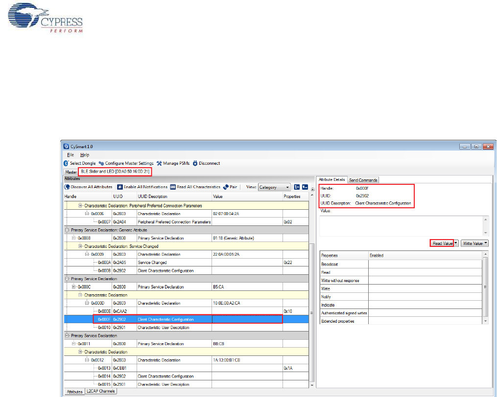
CY8CKIT-042-BLE Bluetooth® Low Energy (BLE) Pioneer Kit Guide, Doc. # 001-93731 Rev. *A 54
Example Projects
11.When all the attributes are listed, locate the attribute with a UUID value of 0xCAA2, which is the
characteristic under CapSense Slider custom service. It will also have a Client Characteristic
Configuration descriptor (UUID 0x2902). The properties of the descriptor appear in the Attribute
Details window, as shown in Figure 4-16. Click Read Value to read the existing Client Character-
istic Configuration Descriptor (CCCD) value.
Figure 4-16. Read CCCD for CapSense Slider Characteristic
12.Modify the Value field of CCCD to '01:00' and click Write Value. This enables the notifications on
the CapSense Slider characteristic. The notifications received are displayed in the Value field of
the CapSense Slider characteristic.
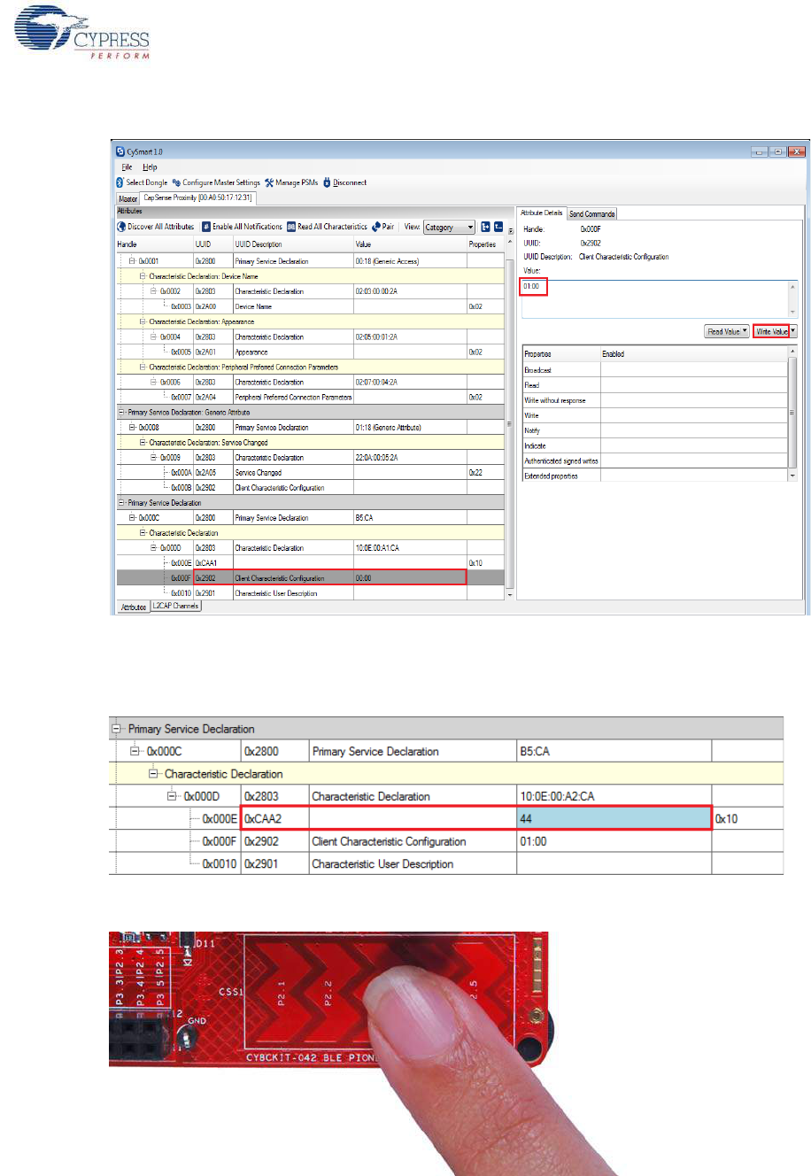
CY8CKIT-042-BLE Bluetooth® Low Energy (BLE) Pioneer Kit Guide, Doc. # 001-93731 Rev. *A 55
Example Projects
Figure 4-17. Write CCCD to Enable Notifications
13.Swipe your finger on the CapSense slider on the BLE Pioneer kit, as shown in Figure 4-19 and
see the notification values in the CapSense Slider value field, as shown in Figure 4-18.
Figure 4-18. CapSense Slider Notification Received
Figure 4-19. CapSense Slider
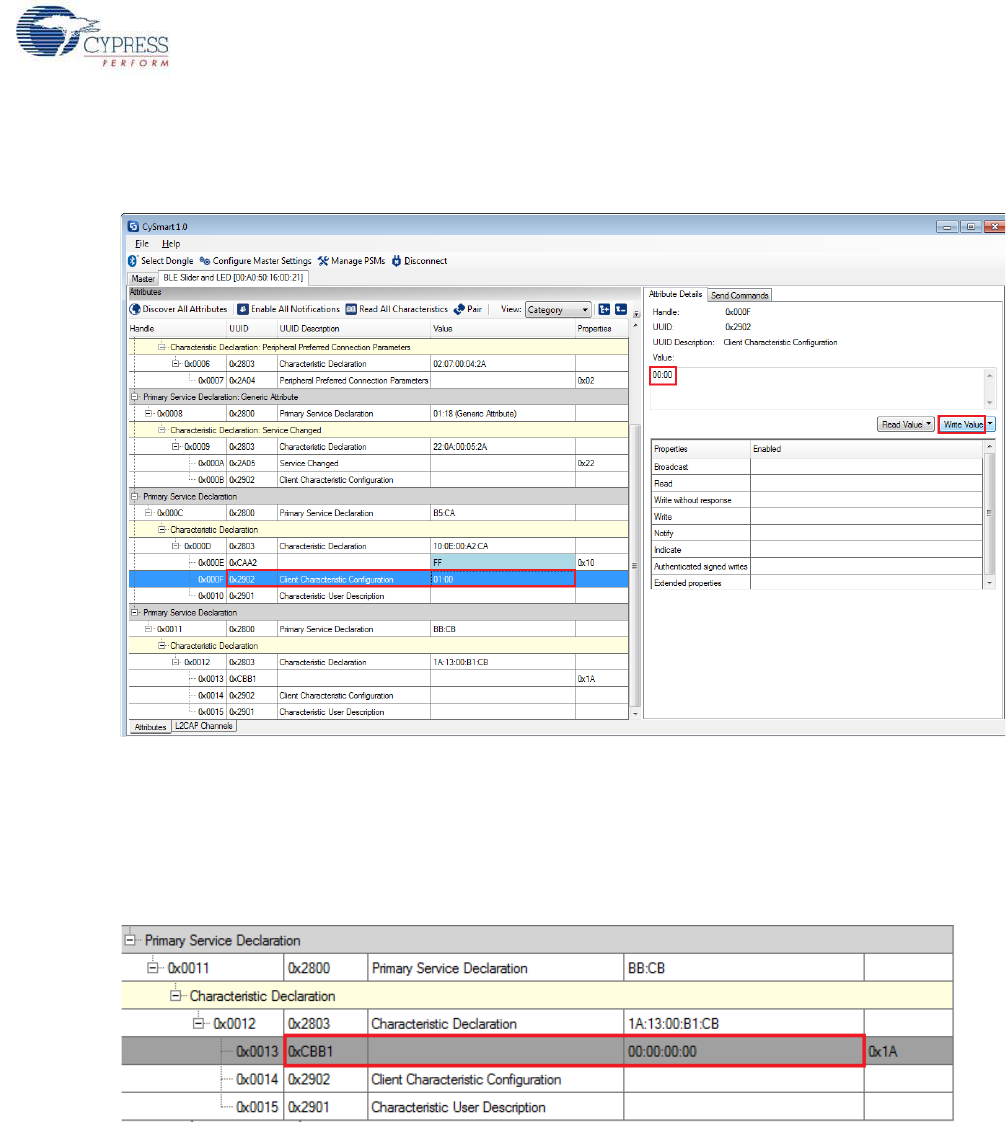
CY8CKIT-042-BLE Bluetooth® Low Energy (BLE) Pioneer Kit Guide, Doc. # 001-93731 Rev. *A 56
Example Projects
14.Modify the Value field of the Client Characteristic Configuration descriptor to '00:00' to disable
notifications.
Figure 4-20. Disable Notifications
15.Now, locate the UUID value of 0xCBB1, which is the RGB LED Control characteristic. Under the
Attribute Details tab on the right, the read and write properties are enabled. Click Read Value to
read the existing 4-byte onboard RGB LED color information, as shown in Figure 4-21. The first
three bytes have the color values Red, Green, and Blue; the fourth byte is the overall intensity
value, all in the range of hexadecimal 0x00 to 0xFF.
Figure 4-21. Read RGB LED Control Characteristic Value
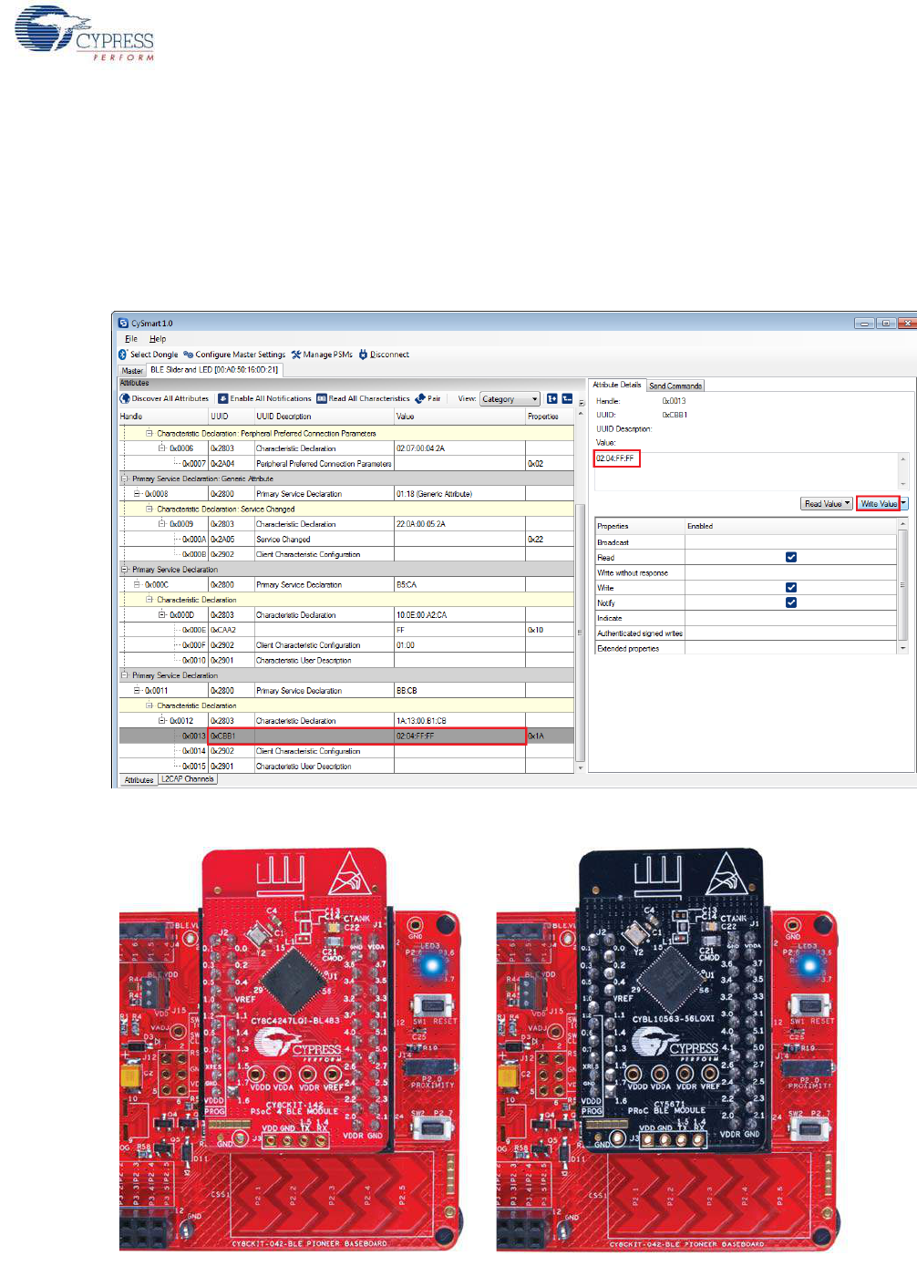
CY8CKIT-042-BLE Bluetooth® Low Energy (BLE) Pioneer Kit Guide, Doc. # 001-93731 Rev. *A 57
Example Projects
16.Modify the four bytes of data in the Value field and click Write Value. You will see the
corresponding change in the color and intensity of the RGB LED on the BLE Pioneer kit, as
shown in Figure 4-22. The RGB LED will be on for 3 seconds before switching off to conserve
power.
Note: If the BLE Pioneer kit is powered from a coin cell and not the USB Vbus, then the color
mixing and intensity will vary. This is because the coin cell provides a lower driving voltage for
RGB LEDs.
Figure 4-22. Write RGB LED Control Characteristic Value
Figure 4-23. RGB LED Control with PSoC 4 BLE Module and PRoC BLE Module
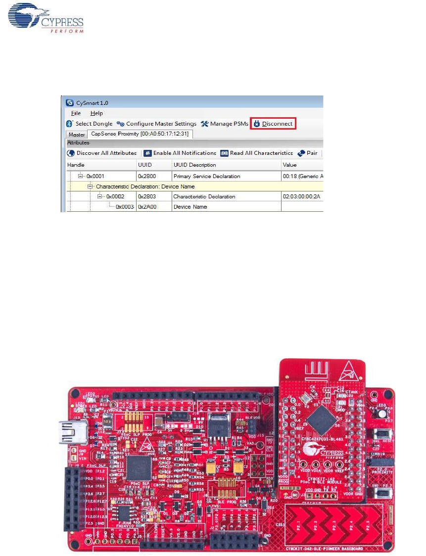
CY8CKIT-042-BLE Bluetooth® Low Energy (BLE) Pioneer Kit Guide, Doc. # 001-93731 Rev. *A 58
Example Projects
17.To disconnect from the device, click Disconnect, as shown in Figure 4-24.
Figure 4-24. Disconnect from the Device
18.To connect to this peripheral again, restart advertising by pressing the user button (SW2) on the
BLE Pioneer kit. Advertising is indicated by the blinking red LED.
4.2.4.2 CySmart iOS/Android App
To verify the CapSense and LED project using the CySmart mobile application (see CySmart iOS/
Android Application on page 152), follow these steps:
1. To verify the PSoC_4_BLE_CapSense_Slider_LED project, plug in the PSoC 4 BLE Module on
the baseboard.
Figure 4-25. BLE Pioneer Kit with PSoC 4 BLE Module
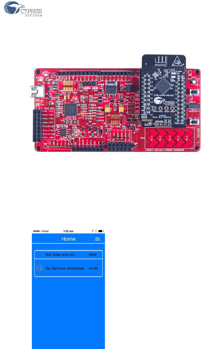
CY8CKIT-042-BLE Bluetooth® Low Energy (BLE) Pioneer Kit Guide, Doc. # 001-93731 Rev. *A 59
Example Projects
To verify the PRoC_BLE_CapSense_Sider_LED project, plug in the PRoC BLE Module on the
baseboard.
Figure 4-26. BLE Pioneer Kit with PRoC BLE Module
2. Plug the BLE Pioneer kit into the PC to power using the J13 USB connector.
3. Program the kit with the CapSense and LED example projects. See Using Example Projects on
page 42 for programming instructions.
4. Press the user button (SW2) on the BLE Pioneer kit to start the advertisement. This is indicated
by the blinking red LED on the BLE Pioneer kit.
5. Open the application on the mobile device. If Bluetooth is not enabled on the device, the
application will ask to enable it.
6. After Bluetooth is enabled, the application will automatically search for available BLE peripherals
and list them. Select the BLE Slider and LED peripheral as shown in Figure 4-27.
Figure 4-27. BLE Slider and LED Peripheral
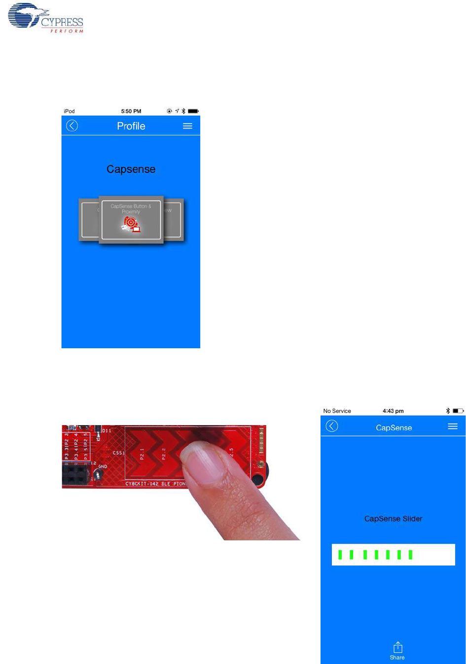
CY8CKIT-042-BLE Bluetooth® Low Energy (BLE) Pioneer Kit Guide, Doc. # 001-93731 Rev. *A 60
Example Projects
7. When connected, the application will list the supported profiles by the peripherals. Scroll and
select the CapSense page, as shown in Figure 4-28.
Figure 4-28. CapSense Service Page
8. Swipe your finger on the CapSense slider on the BLE Pioneer kit and see a similar response on
the CapSense page in the CySmart application (Figure 4-29).
Figure 4-29. CapSense Slider
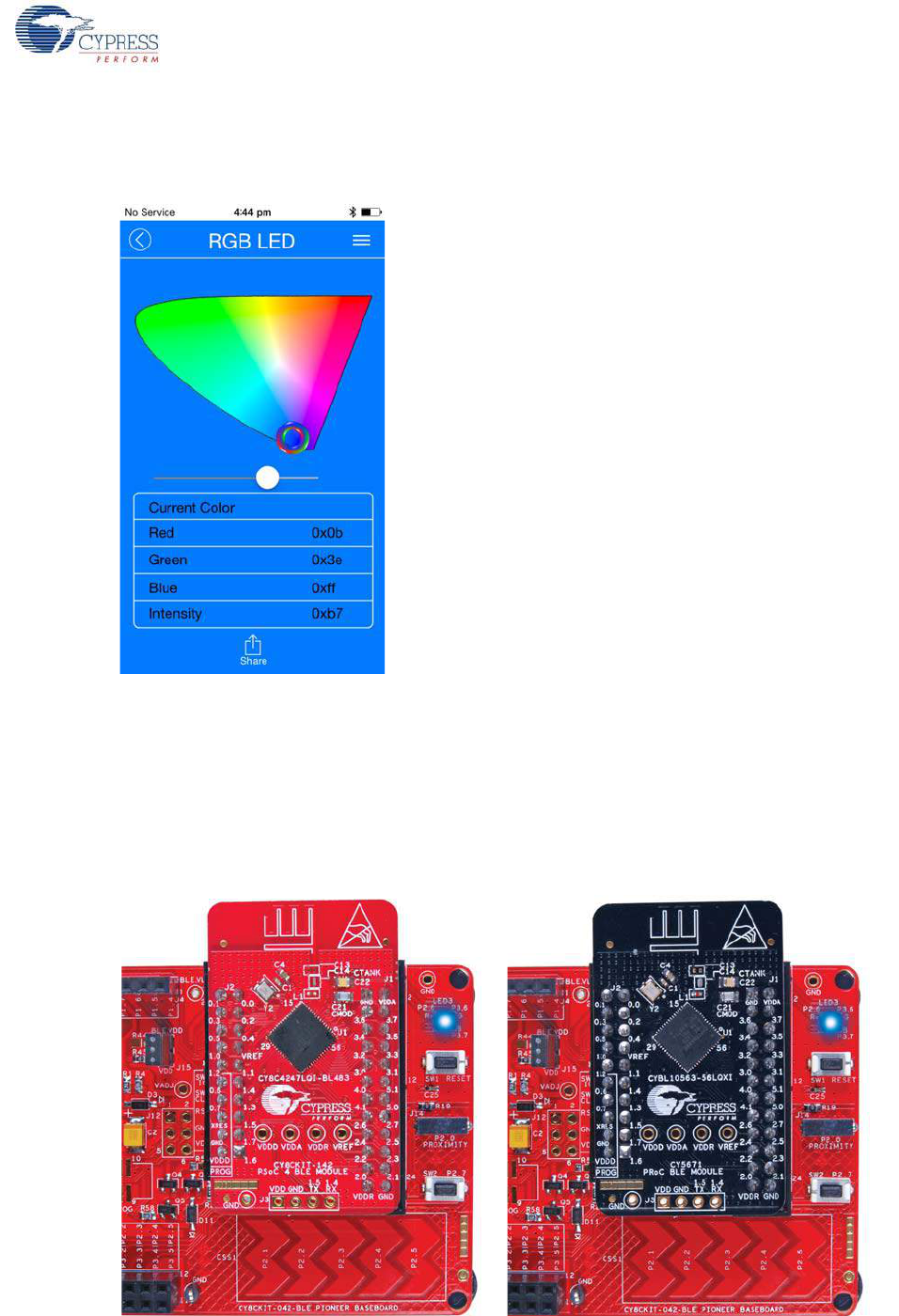
CY8CKIT-042-BLE Bluetooth® Low Energy (BLE) Pioneer Kit Guide, Doc. # 001-93731 Rev. *A 61
Example Projects
9. Press the back button in the top left corner of the application to return to the service selection
page. Scroll and tap on the RGB LED service shown in Figure 4-30.
Figure 4-30. RGB LED Service Page
10.On the RGB LED service page, swipe over the color gamut to see a similar color response on the
BLE Pioneer kit RGB LED. The slider below the color gamut controls the intensity of the RGB
LED color. The RGB LED will be on for 3 seconds before switching off. This is done to conserve
power.
If the BLE Pioneer kit is powered from the coin cell and not the USB Vbus power, then the color
mixing and intensity will vary. This is because the coin cell provides a lower driving voltage for
RGB LEDs.
Figure 4-31. RGB LED Control with PSoC 4 BLE Module and PRoC BLE Module
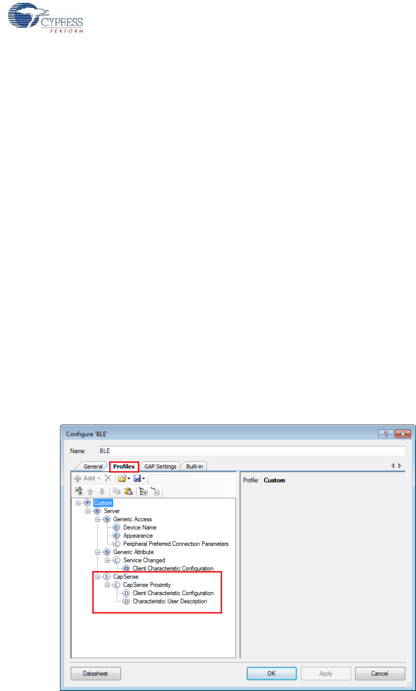
CY8CKIT-042-BLE Bluetooth® Low Energy (BLE) Pioneer Kit Guide, Doc. # 001-93731 Rev. *A 62
Example Projects
11.To disconnect from the BLE Pioneer kit, return to the CySmart app home screen by pressing the
back button.
12.To reconnect to the peripheral, press the user button (SW2) on the BLE Pioneer kit again and
then scan for devices using CySmart mobile app.
4.3 CapSense Proximity
4.3.1 Project Description
This project demonstrates BLE connectivity between the BLE Pioneer kit (acting as a peripheral and
server device) and the BLE dongle or mobile device running the CySmart application (acting as a
central and client device). This project demonstrates the following:
■Advertisement with timeout
■Connection with any BLE Central device
■One custom service
■Data transfer over BLE custom service using notifications
■Low-power mode implementation for coin cell operation
The BLE profile in this project consists of a single BLE custom service, called CapSense. The
CapSense service consists of a custom characteristic, termed as CapSense Proximity. The
CapSense proximity characteristic is used to send one byte data, ranging from 0 to 255, as
notification to the client device. This data is the difference count read by the CapSense component
on the one-wire proximity sensor (J14) connected on the kit. This characteristics supports
notification, which allows the BLE server to send data to the connected client device whenever new
data is available.
The properties for the custom service/characteristics are configured in the BLE component under the
Profiles tab, as shown in Figure 4-32.
Figure 4-32. Attributes Configuration in BLE Component for CapSense Proximity
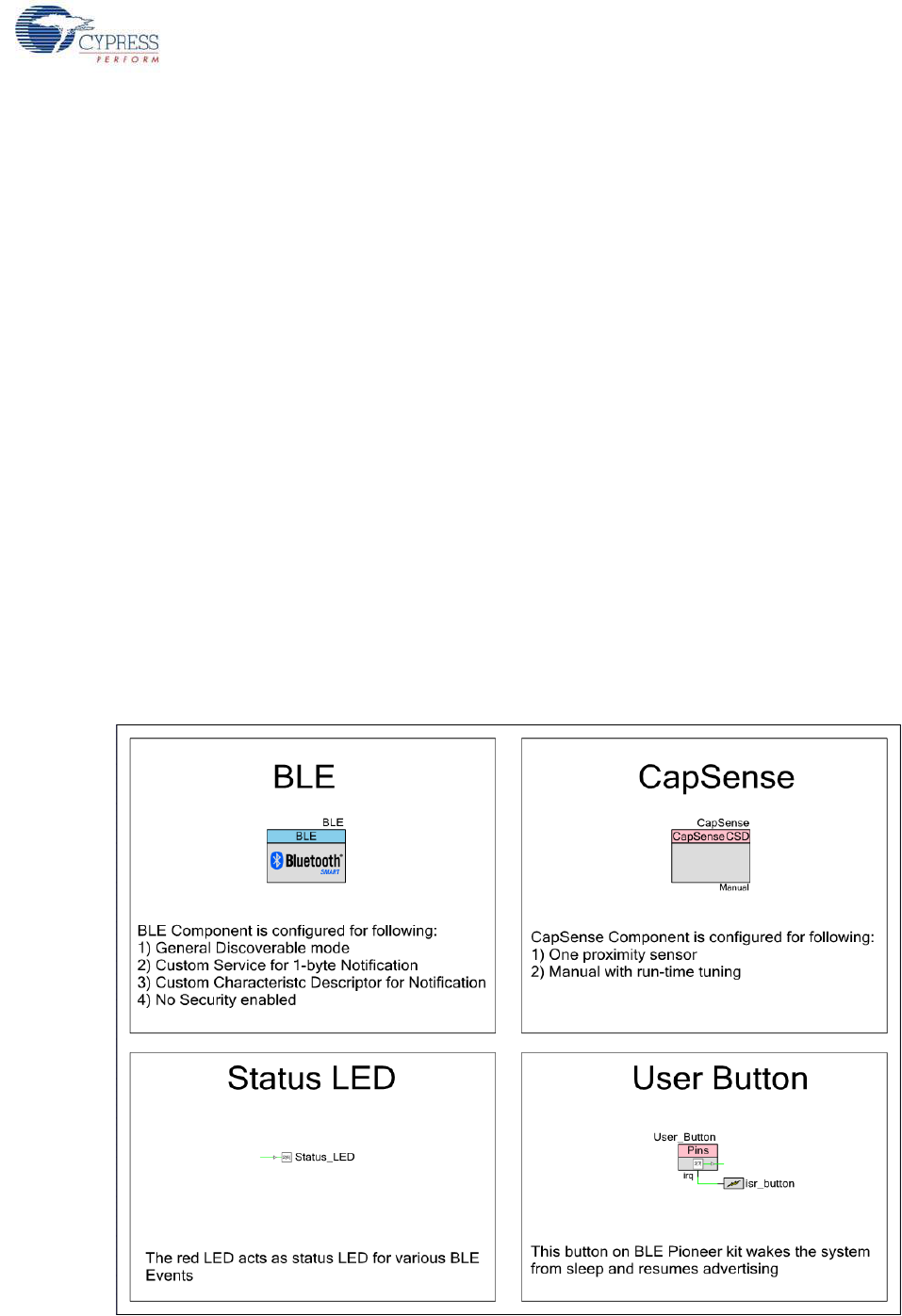
CY8CKIT-042-BLE Bluetooth® Low Energy (BLE) Pioneer Kit Guide, Doc. # 001-93731 Rev. *A 63
Example Projects
The project consists the following files:
■main.c/.h
These files contain the main function, which is the entry point and execution of the firmware appli-
cation. It contains function definition for initialization of the system and reading the CapSense
proximity data from the CapSense component.
■BLEApplications.c/.h
These files contain all the macros and function definitions related to BLE communication and
operation. It contains the event callback function definition that is registered with the BLE compo-
nent startup and used by the component to send BLE-related event from the BLE stack to the
application layer for processing. It contains a method to send CapSense notifications to the client
device. It updates the BLE Connection parameter, which is important for low-power mode usage.
■HandleLowPower.c/.h
These files contain the function to handle low-power mode. This function is continuously called in
the main loop and is responsible for pushing the BLE hardware block (BLESS) as well as the
CPU to Deep Sleep mode as much as possible. The wakeup source is either the BLE hardware
block Link Layer internal timer or the interrupt from the user button press (SW2). This allows for
very low-power mode implementation and operation using a coin cell.
The red LED is used as the status LED and provides visual confirmation on advertising or
connection states. A blinking red LED indicates advertising state.
Two projects demonstrate this functionality on two different devices:
■PSoC_4_BLE_CapSense_Proximity works with the PSoC 4 BLE Module.
■PRoC_BLE_CapSense_Proximity works with the PRoC BLE Module.
Figure 4-33. Top Design for PSoC_4_BLE_CapSense_Proximity Project
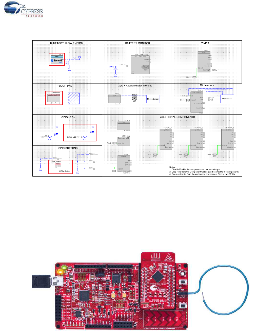
CY8CKIT-042-BLE Bluetooth® Low Energy (BLE) Pioneer Kit Guide, Doc. # 001-93731 Rev. *A 64
Example Projects
Figure 4-34. Top Design for PRoC_BLE_CapSense_Proximity Project
4.3.2 Hardware Connections
■Ensure that the correct BLE module is placed on the baseboard corresponding to the project
being used. PSoC_4_BLE_CapSense_Proximity works with the PSoC 4 BLE Module.
PRoC_BLE_CapSense_Proximity works with the PRoC BLE Module.
■Connect a five-inch wire (provided as part of this kit) to the proximity connector J14 on the
baseboard. Loop the wire as shown in Figure 4-35.
Note: Ensure that the proximity sensor loop wire is kept away as much as possible from the BLE
antenna on the modules.
Figure 4-35. Proximity Sensor Connection on BLE Pioneer Kit with PSoC 4 BLE Module
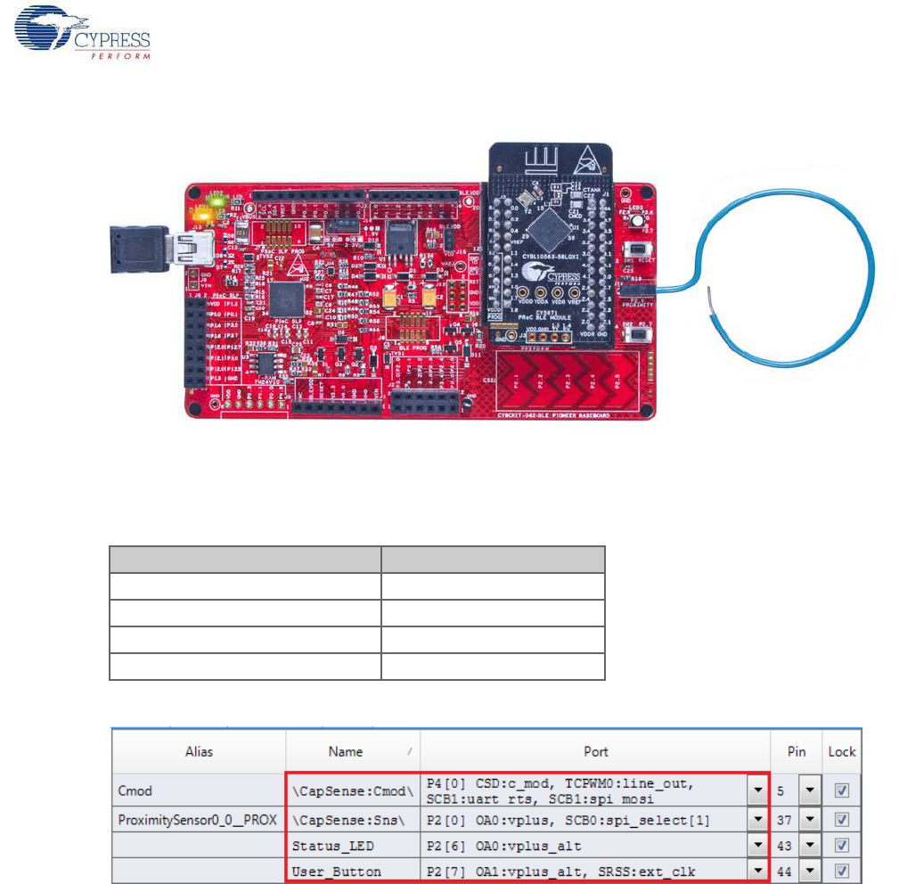
CY8CKIT-042-BLE Bluetooth® Low Energy (BLE) Pioneer Kit Guide, Doc. # 001-93731 Rev. *A 65
Example Projects
Figure 4-36. Proximity Sensor Connection on BLE Pioneer Kit with PRoC BLE Module
The pin assignment for this project is in PSoC_4_BLE_CapSense_Proximity.cydwr/
PRoC_BLE_CapSense_Proximity.cydwr in the Workspace Explorer, as shown in Figure 4-37.
Figure 4-37. Pin Selection for CapSense Proximity Project
Table 4-2. Pin Assignments for CapSense Proximity Project
Pin Name Port Name
CapSense CMOD P4_0
CapSense Proximity Sensor P2_0
User Button P2_7
Status LED P2_6
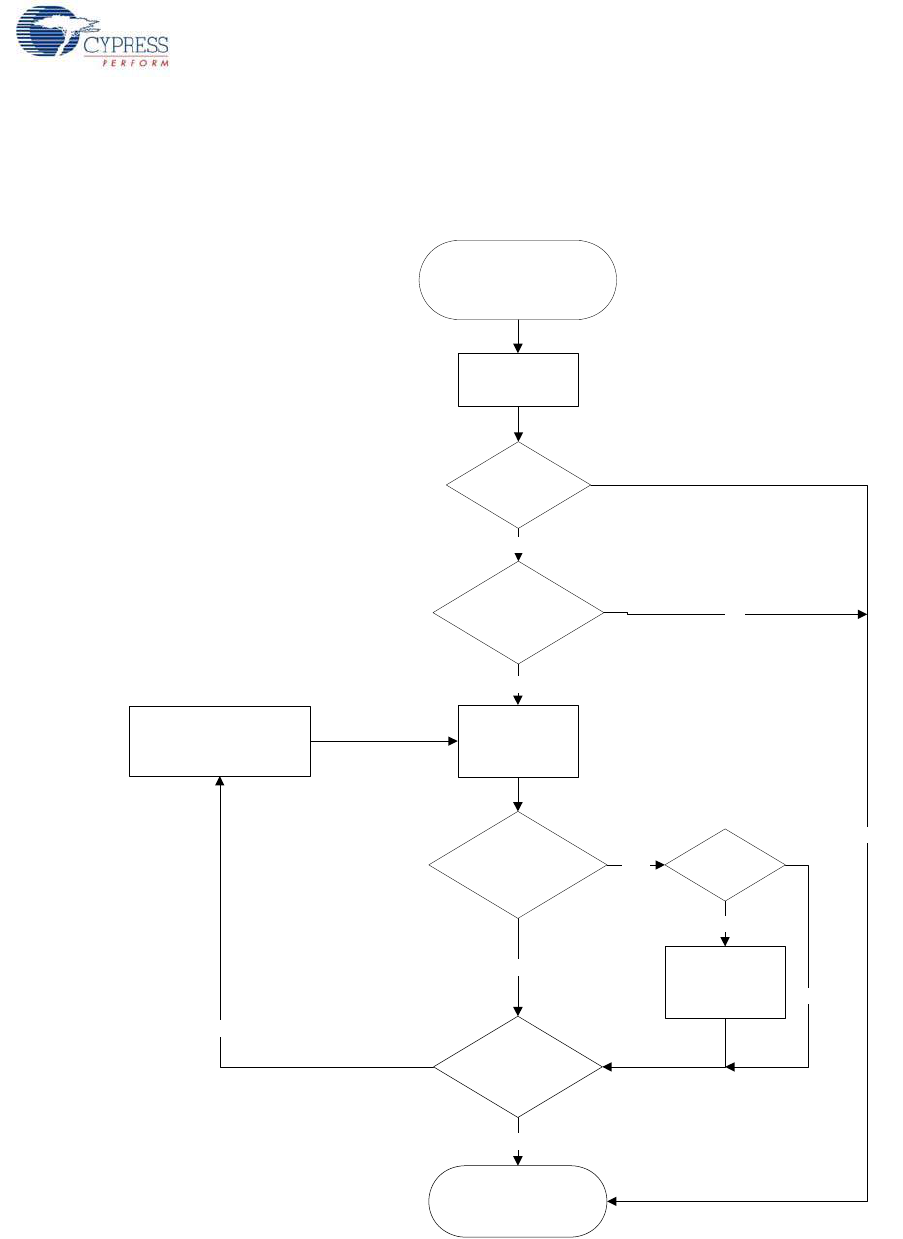
CY8CKIT-042-BLE Bluetooth® Low Energy (BLE) Pioneer Kit Guide, Doc. # 001-93731 Rev. *A 66
Example Projects
4.3.3 Flow Chart
Figure 4-38 shows the flow chart of code implemented.
Figure 4-38. CapSense Proximity Project Flow Chart
Start
Advertisement
Proximity value
Changed?
Send the proximity
data to BLE
Central device
BLE connection
still exists?
YES
NO
YES
Connected to BLE
Central device? NO
Notification
enabled?
YES
NO
System is put in Sleep and
waits for User Button press
NO
Advertisement
Time-out?
NO
System initialized.
Wait for interrupt from User
Button to Wakeup
Put system to low power
mode and wait for interrupt
from BLE Link Layer
YES
YES
Process BLE
events
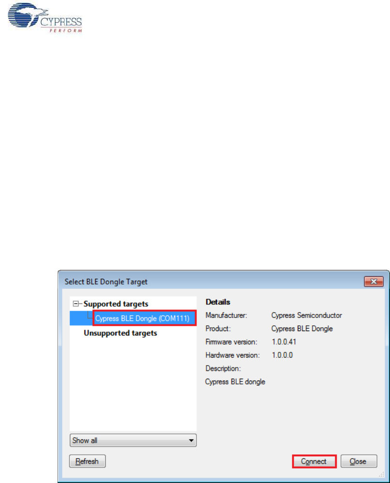
CY8CKIT-042-BLE Bluetooth® Low Energy (BLE) Pioneer Kit Guide, Doc. # 001-93731 Rev. *A 67
Example Projects
4.3.4 Verify Output
The project can be verified by two methods: using the CySmart PC tool and dongle or using the
CySmart iOS/Android BLE app.
To install and use the CySmart PC tool, see CySmart PC Tool on page 160.
To install and use the CySmart iOS/Android app, see CySmart iOS/Android Application on page 152.
4.3.4.1 CySmart PC Tool
To verify the CapSense proximity project using the CySmart PC tool, follow these steps:
Note: See CySmart PC Tool on page 160 to know how to use the tool.
1. Connect the dongle to one of the USB ports on the PC.
2. Start the CySmart PC tool on the PC by going to Start > All Programs > Cypress > CySmart
<version> > CySmart <version>. You will see a list of dongles connected to it. If no dongle is
found, click Refresh. Select the BLE dongle and click Connect.
Figure 4-39. Connect to BLE Dongle
3. Depending on the example project chosen, place the PSoC 4 BLE Module or PRoC BLE Module
on the baseboard.
4. Power the BLE Pioneer kit through the USB connector J13.
5. Connect a five-inch wire (included in the kit) to the proximity sensor connector J14 and make a
loop of it.
6. Program the BLE Pioneer kit with the CapSense proximity example project. Follow the steps in
Using Example Projects on page 42 to program the device.
7. After programming successfully, press the user button (SW2) on the BLE Pioneer kit to start the
advertisement. This is indicated by a blinking red LED on the baseboard.
8. On the CySmart PC tool, click Start Scan to see the list of available BLE peripheral devices. You
can recognize your device by the device name and Bluetooth address on the list. This should be
the same as the one in the Gap Settings tab of the BLE component GUI in PSoC Creator.
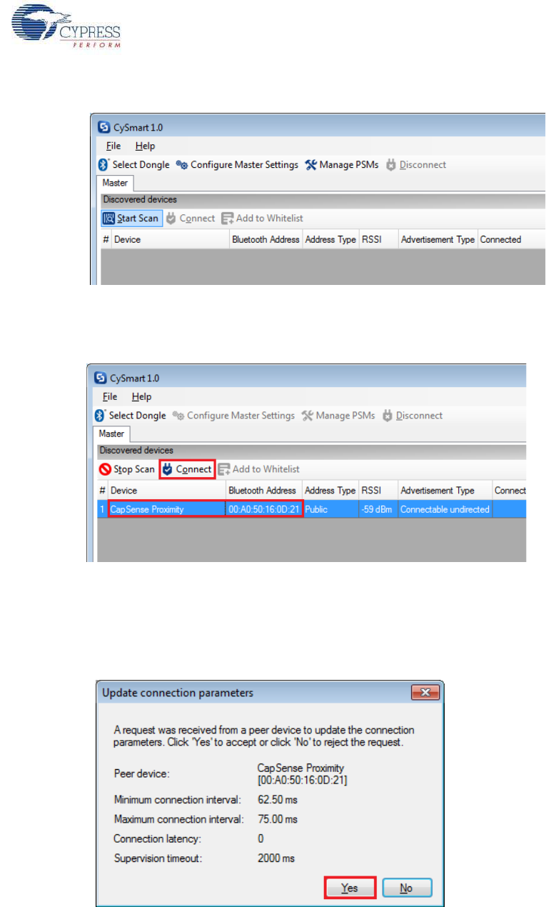
CY8CKIT-042-BLE Bluetooth® Low Energy (BLE) Pioneer Kit Guide, Doc. # 001-93731 Rev. *A 68
Example Projects
Figure 4-40. Start Scanning
9. After the available devices are listed, double-click CapSense Proximity to connect or click Stop
Scan and then click Connect to connect to the device.
Figure 4-41. Connect to CapSense Proximity Peripheral
10.When the connection is made, the CySmart PC tool will display a message for the Update Con-
nection parameter. This is the request from the BLE peripheral to update the existing connection
parameters, such as connection interval, latency, and supervision timeout, to a new value. Select
Yes, as shown in Figure 4-42.
Figure 4-42. Update Connection Parameter Option
Note: If you select No, the project will still work. However, the current consumption will be higher
due to faster connection interval.
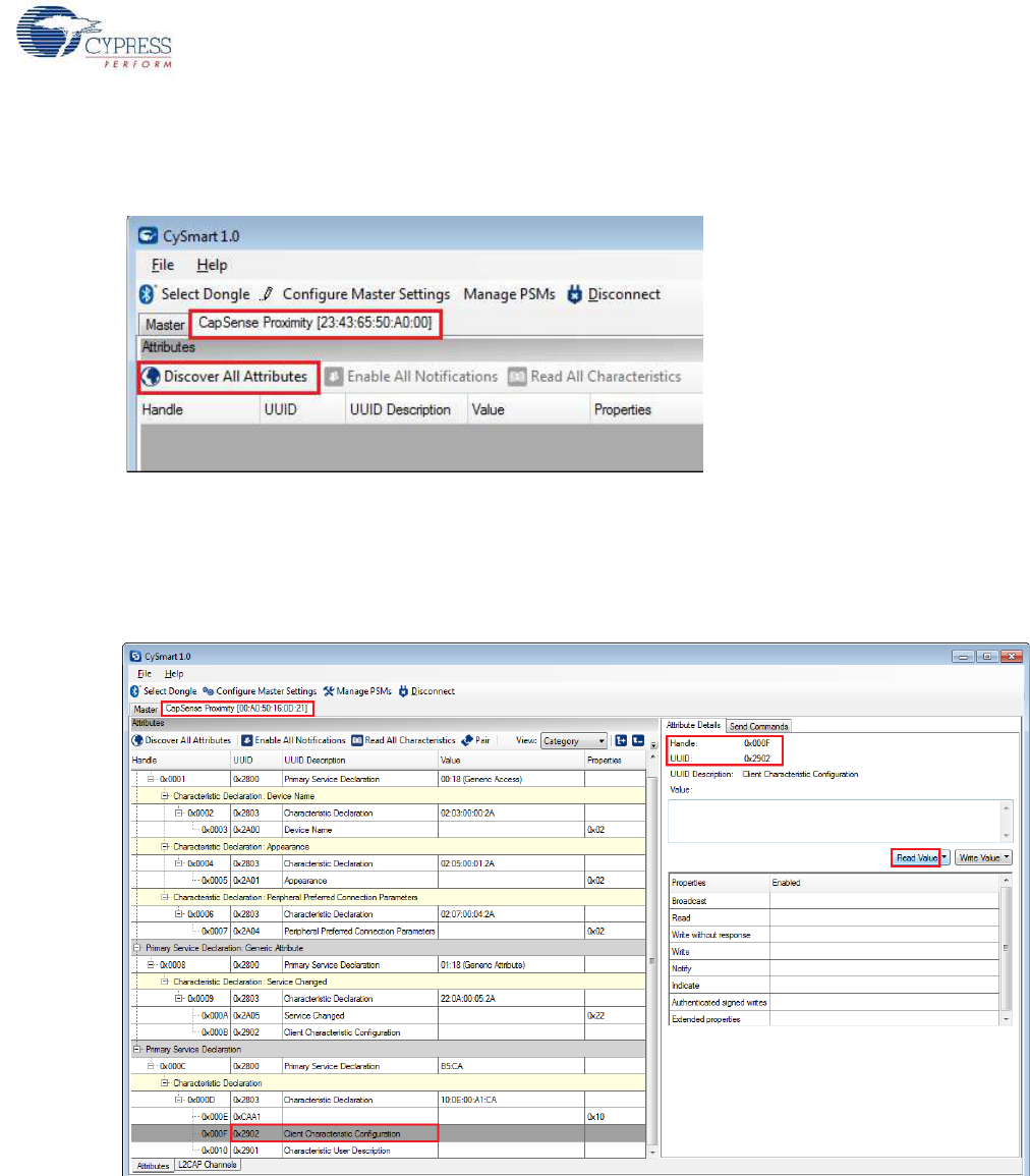
CY8CKIT-042-BLE Bluetooth® Low Energy (BLE) Pioneer Kit Guide, Doc. # 001-93731 Rev. *A 69
Example Projects
11.If the connection is successful, you will see another tab opening besides the Master tab. Click
Discover All Attributes to find all the services and attributes supported by the BLE peripheral.
Figure 4-43. Discover All Attributes
12.When all the attributes are listed, locate the UUID value of 0xCAA1, which is the characteristic
for CapSense Proximity. It will also have a Client Characteristic Configuration descriptor
(UUID 0x2902). The properties of the descriptor appear in the Attribute Details window, as shown
in Figure 4-44. Click Read Value to read the existing CCCD value.
Figure 4-44. Read CapSense Proximity CCCD
13.Modify the Value field to '01:00' and click Write Value. This enables the notifications on the
CapSense Proximity characteristic. The notifications received are displayed in the Value field of
the CapSense Proximity characteristic.
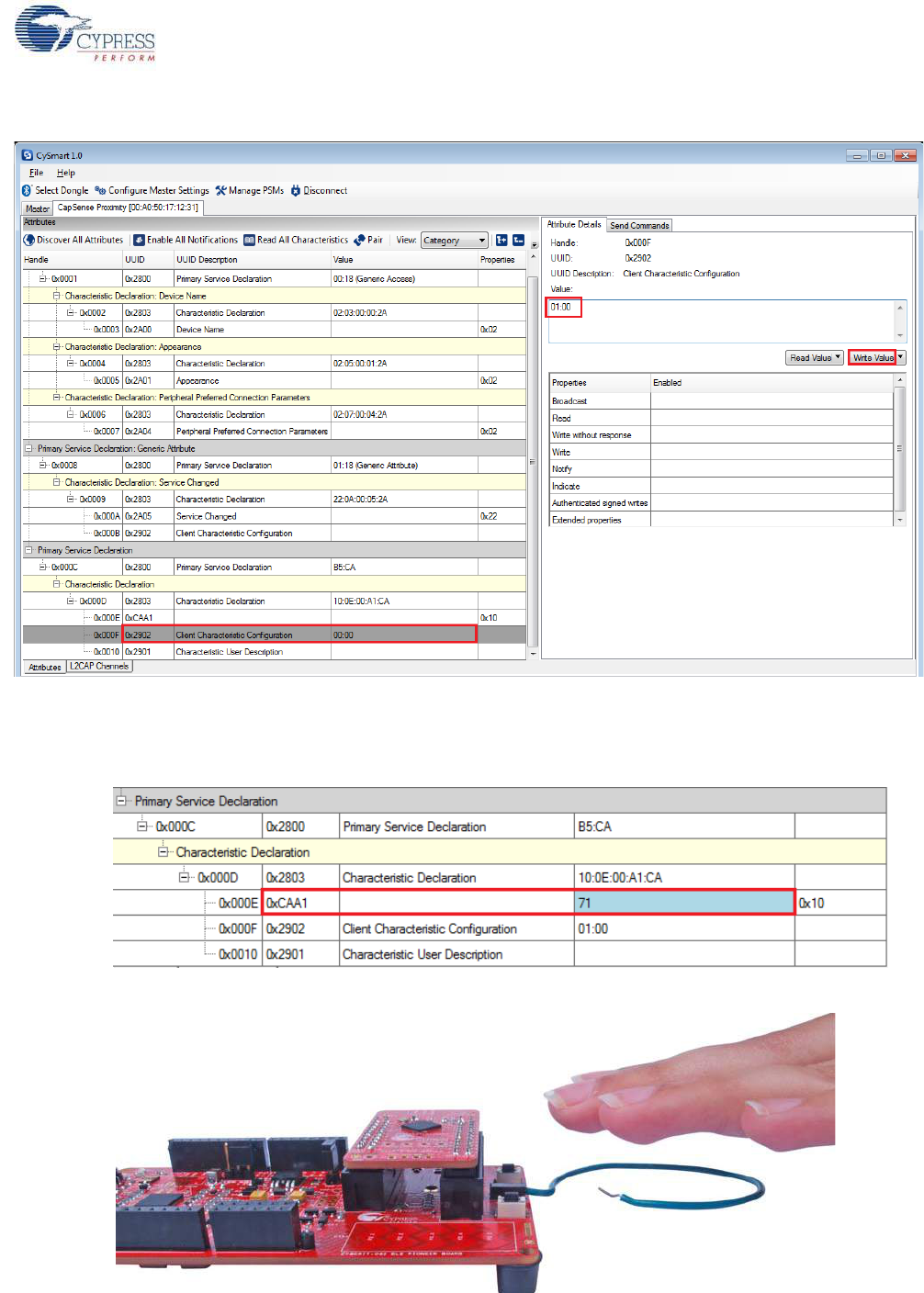
CY8CKIT-042-BLE Bluetooth® Low Energy (BLE) Pioneer Kit Guide, Doc. # 001-93731 Rev. *A 70
Example Projects
Figure 4-45. Write CCCD to Enable Notifications
14.Bring your hand closer to the proximity sensor on the BLE Pioneer kit, as shown in Figure 4-47
and observe the value changing in the characteristic value field, as shown in Figure 4-46.
Figure 4-46. CapSense Proximity Notification Received
Figure 4-47. CapSense Proximity Sensing with PSoC 4 BLE Module
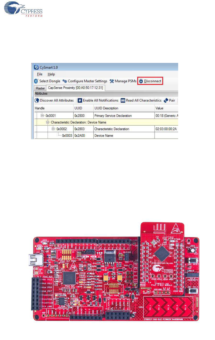
CY8CKIT-042-BLE Bluetooth® Low Energy (BLE) Pioneer Kit Guide, Doc. # 001-93731 Rev. *A 71
Example Projects
15.Modify the Value field of the Client Characteristic Configuration descriptor to '00:00' to disable
notifications.
16.To disconnect from the device, click Disconnect, as shown in Figure 4-48.
Figure 4-48. Disconnect from the Device
17.Press user button (SW2) to wake up from sleep and restart the advertisement for the next
connection.
4.3.4.2 CySmart iOS/Android App
To learn how to use the CySmart iOS/Android application, see CySmart iOS/Android Application on
page 152 or the app user guide.
To verify the CapSense proximity project using the CySmart mobile app, follow these steps:
1. To verify the PSoC_4_BLE_CapSense_Proximity project, plug in the PSoC 4 BLE Module on the
baseboard.
Figure 4-49. BLE Pioneer Kit with PSoC 4 BLE Module
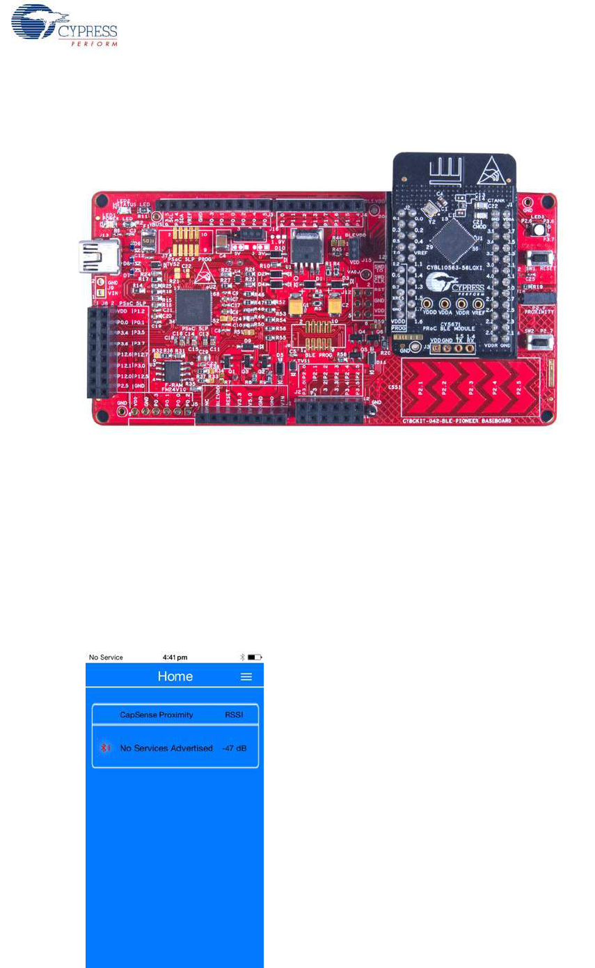
CY8CKIT-042-BLE Bluetooth® Low Energy (BLE) Pioneer Kit Guide, Doc. # 001-93731 Rev. *A 72
Example Projects
To verify the PRoC_BLE_CapSense_Proximity project, plug in the PRoC BLE Module on the
baseboard.
Figure 4-50. BLE Pioneer Kit with PRoC BLE Module
2. Connect the five-inch wire as a loop to the proximity connector J14 on the baseboard.
3. Plug the BLE Pioneer kit into the PC for power, using the J13 USB connector.
4. Program the kit with the CapSense proximity example project. Follow steps in Using Example
Projects on page 42 to program the device.
5. Press the user button (SW2) on the BLE Pioneer kit to start the advertisement.
6. Open the CySmart app on the mobile device. If Bluetooth is not enabled on the device, the app
will ask to enable it.
7. The app will automatically search for available BLE peripherals and list them. Select the
CapSense Proximity peripheral, as shown in Figure 4-51.
Figure 4-51. Connect to CapSense Proximity Peripheral
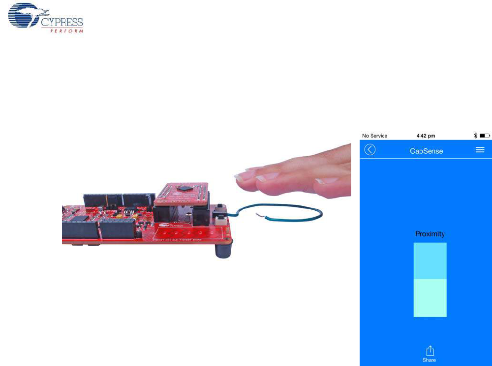
CY8CKIT-042-BLE Bluetooth® Low Energy (BLE) Pioneer Kit Guide, Doc. # 001-93731 Rev. *A 73
Example Projects
8. When connected, the app will list the services supported by the peripherals. Scroll and select the
CapSense service.
9. When the CapSense service page opens, bring your hand near the sensor wire on the BLE
Pioneer kit and see a similar response in the app as a bar graph, as shown in Figure 4-52.
Figure 4-52. CapSense Proximity Sensing with PSoC 4 BLE Module
10.To disconnect from the BLE Pioneer kit, return to the device selection screen on the CySmart
app.
11.To reconnect to the peripheral, press the user button (SW2) on the BLE Pioneer Kit to restart the
advertisement and scan for the device in the CySmart app.
4.4 BLE Central Mode
4.4.1 Project Description
The BLE projects described above have been functioning as BLE peripheral devices. This means
that the firmware role was set to be a BLE peripheral and server; another device such as the
CySmart PC tool or CySmart mobile application will connect to it and collect the data.
This example project demonstrates the BLE central and client mode where it will scan for a periph-
eral device, connect to it, and send commands. In this project, the BLE Pioneer kit scans and auto-
connects to a particular peripheral device supporting Immediate Alert Service (IAS). Whenever the
peripheral with a predetermined address is found, a connection request is sent followed by discover-
ing the attributes. When the discovery is over, you can send one of the three alert levels to the BLE
peripheral device over the IAS. This is done by pressing the SW2 button on the BLE Pioneer kit and
cycling through the alert levels.
The BLE central project supports low-power mode operation, where the firmware supports BLESS
and CPU Deep Sleep mode whenever possible. The system remains in deep sleep when discon-
nected. Press SW2 to wake up the system and start scanning (blinking blue LED). The scanning
timeout interval is set to 30 seconds. If the particular BLE peripheral device is found advertising
before timeout, a connection is made (blue LED always ON). If no such device is found, then the
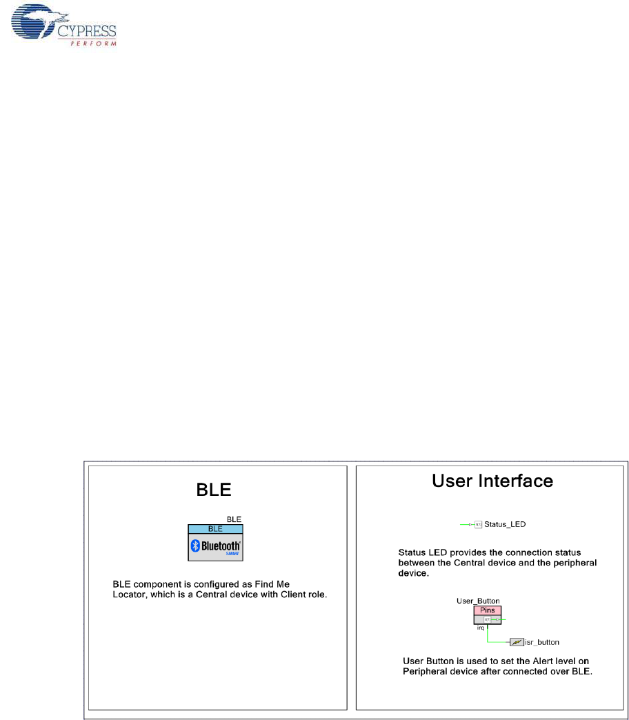
CY8CKIT-042-BLE Bluetooth® Low Energy (BLE) Pioneer Kit Guide, Doc. # 001-93731 Rev. *A 74
Example Projects
system stops scanning and returns to Deep Sleep mode (LED OFF). Press SW2 again to wake the
system and restart scanning.
To aid in evaluation, the BLE peripheral project with the particular BD address is provided in the
same workspace. This peripheral project supports IAS and has fixed BD address that the central
device will recognize and auto-connect to. This peripheral project is programmed on the BLE dongle
and powered through the USB port of PC. The received alert levels (No, Mid, and High alert) on the
BLE dongle are represented by different LED status. No Alert is represented by LED OFF, Mid Alert
by blinking LED, and High Alert with LED always ON. Upon each successive button press on the
BLE Pioneer kit, the LED state on the BLE dongle changes in a circular fashion.
Two projects demonstrate the BLE Central functionality on the two devices:
■PSoC_4_BLE_Central_IAS works with the PSoC 4 BLE Module.
■PRoC_BLE_Central_IAS works with the PRoC BLE Module.
Additionally, the BLE_Dongle_Peripheral_IAS project is to be programmed on the dongle. This
project is present in both the PSoC_4_BLE_Central_IAS and the PRoC_BLE_Central_IAS work-
space and can be used to program the dongle separately.
Note: If the dongle is programmed with the BLE_Dongle_Peripheral_IAS example, it will not work
with the CySmart PC utility. Reprogram the dongle with the CySmart firmware according to Updating
BLE Dongle for CySmart PC Tool on page 33 to use the CySmart PC tool.
Figure 4-53. PSoC_4_BLE_Central_IAS TopDesign
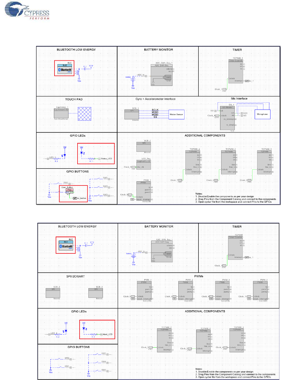
CY8CKIT-042-BLE Bluetooth® Low Energy (BLE) Pioneer Kit Guide, Doc. # 001-93731 Rev. *A 75
Example Projects
Figure 4-54. PRoC_BLE_Central_IAS TopDesign
Figure 4-55. BLE_Dongle_Peripheral_IAS TopDesign
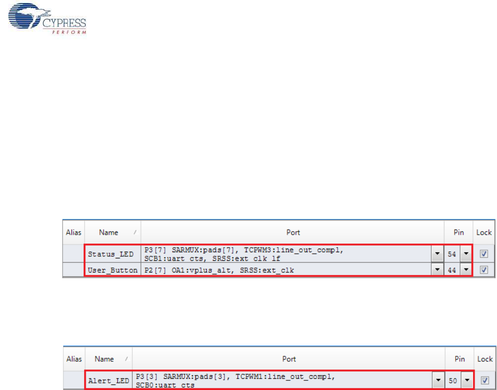
CY8CKIT-042-BLE Bluetooth® Low Energy (BLE) Pioneer Kit Guide, Doc. # 001-93731 Rev. *A 76
Example Projects
4.4.2 Hardware Connections
No specific hardware connections are required for this project because all connections are
hardwired on the board.
Ensure that the correct BLE module is placed on the baseboard corresponding to the project being
used. PSoC_4_BLE_Central_IAS works with the PSoC 4 BLE Module. PRoC_BLE_Central_IAS
works with the PRoC BLE Module. BLE_Dongle_Peripheral_IAS is the common project for both
workspaces and programs the BLE dongle with peripheral mode firmware.
The pin assignment for this project is in PSoC_4_BLE_Central_IAS.cydwr/
PRoC_BLE_Central_IAS.cydwr in the Workspace Explorer, as shown in Figure 4-56.
Figure 4-56. Pin Selection for BLE IAS Central Example Project
Similarly, the pin assignment for the dongle peripheral project is in
BLE_Dongle_Peripheral_IAS.cydwr in the Workspace Explorer as shown in Figure 4-57.
Figure 4-57. Pin Selection for BLE IAS Peripheral Example Project
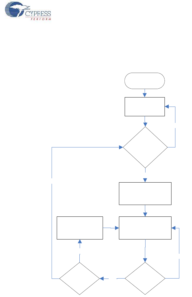
CY8CKIT-042-BLE Bluetooth® Low Energy (BLE) Pioneer Kit Guide, Doc. # 001-93731 Rev. *A 77
Example Projects
4.4.3 Flow Chart
Figure 4-58 shows the flow chart for the IAS client mode example project.
Figure 4-58. IAS Client Mode Flow Chart
Start
Initialize BLE
Module
Button press
detected ?
Yes
Discovered
peripheral with
IAS Peripheral
Address ?
Initiate and complete
connect operation .
Provide LED indication
on connection complete
Write the next Alert
level (Alert levels will
be repeated )
Yes
No
Check for configured
Button press event
No
Yes
Does
connection
exist ?
No
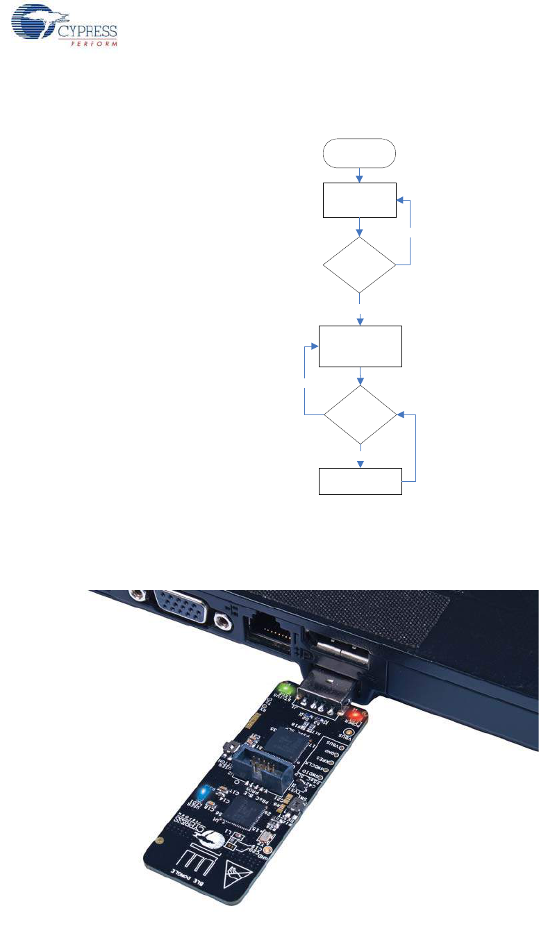
CY8CKIT-042-BLE Bluetooth® Low Energy (BLE) Pioneer Kit Guide, Doc. # 001-93731 Rev. *A 78
Example Projects
Figure 4-59 shows the flow chart for the IAS peripheral mode example project.
Figure 4-59. IAS Peripheral Mode Flow Chart
4.4.4 Verify Output
1. Connect the BLE dongle to one of the USB ports on the PC.
Figure 4-60. Connect Dongle to USB Port
Start
Initialize BLE
Module and start
Advertisement
Yes
Connect
request from
Central device
?
Complete connect
operation and wait for
Alert notifications
Configure LED as per
alert level
No
Yes
No
Valid Alert level
is notified ?
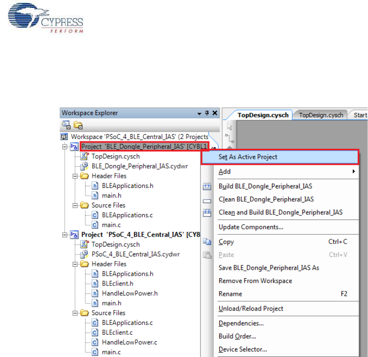
CY8CKIT-042-BLE Bluetooth® Low Energy (BLE) Pioneer Kit Guide, Doc. # 001-93731 Rev. *A 79
Example Projects
2. In the PSoC Creator Workspace Explorer, right-click on the BLE_Dongle_Peripheral_IAS
project and select Set As Active Project, as shown in Figure 4-61.
Figure 4-61. Set Dongle Peripheral Project as Active
3. Program the dongle with the BLE_Dongle_Peripheral_IAS project described in Using Example
Projects on page 42.
Note: Do not update the public device address (inside the BLE component) for the
BLE_Dongle_Peripheral_IAS example project. This is because the central example project
looks for a particular public address equal to the one set on the peripheral BLE component.
Changing the BLE_Dongle_Peripheral_IAS example project public address will lead to no
connection with the BLE Central device on the BLE Pioneer kit.
4. Power the BLE Pioneer kit through USB connector J13.
5. In the Workspace Explorer, right-click on the PSoC_4_BLE_Central_IAS project and select Set
As Active Project, as shown in Figure 4-62.
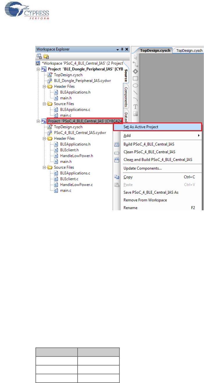
CY8CKIT-042-BLE Bluetooth® Low Energy (BLE) Pioneer Kit Guide, Doc. # 001-93731 Rev. *A 80
Example Projects
Figure 4-62. Set Central IAS Project as Active
6. Program the BLE Pioneer kit with either the PSoC_4_BLE_Central_IAS or the
PRoC_BLE_Central_IAS project, depending on the BLE module placed on the BLE Pioneer kit.
7. Press button SW2 on the BLE Pioneer kit to wake the system and start scanning. Scanning is
indicated by a blinking LED.
8. Wait for the BLE connection between the dongle and the Pioneer baseboard. The connection
success status is indicated on the baseboard in the following three stages:
a. Fast blinking blue LED represents scanning mode. During this mode, the BLE Pioneer kit is
scanning for peripheral devices.
b. Slow blinking blue LED represents discovery mode. During this mode, the BLE Pioneer kit has
found the dongle peripheral device and has started the connection procedure.
c. The blue LED remains on, representing the connected mode. This mode indicates that the
peripheral device has been connected and the application can now send alert levels.
9. Press button SW2 on the BLE Pioneer kit to send the next alert level to the dongle. The alert level
will rotate from No Alert to Mid Alert to High Alert.
10.Check if the LED behavior changes for each alert notification on the dongle according to the
following table:
Alert Level LED State
No Alert LED OFF
Mild Alert LED blinking
High Alert LED ON
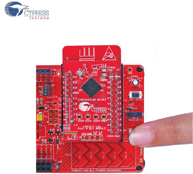
CY8CKIT-042-BLE Bluetooth® Low Energy (BLE) Pioneer Kit Guide, Doc. # 001-93731 Rev. *A 81
Example Projects
Figure 4-63. User Button on BLE Pioneer Kit with PSoC 4 BLE Module
Note: To revert the CySmart functionality to the dongle, program the dongle hex file, as described in
Updating BLE Dongle for CySmart PC Tool on page 33.
4.5 BLE Dongle and LED Control
4.5.1 Project Description
This firmware supports the CySmart debug tool (see CySmart PC Tool on page 160) by acting as the
BLE host emulator. This is the default firmware that comes in the BLE dongle shipped with the kit.
This project additionally demonstrates LED brightness control via a custom BLE profile, which works
with the CapSense slider example explained in CapSense Slider and LED on page 47.
The device will scan for the peripheral acting as a CapSense slider and LED device, and connect to
it automatically. This is achieved by filtering the advertisement packets for the CapSense Slider
service data, which will be sent by the CapSense slider example. Then, it will enable slider
notifications and process the received notifications. Whenever CapSense detects activity, it will
notify the finger location to the dongle; the dongle will update the LED brightness using PWM.
The custom client LED control will be stopped if the CySmart PC tool acquires the dongle. The
dongle will enter the CySmart emulator mode, in which it will process all BLE commands as
triggered by the user via the tool. The project uses custom command/event protocol to exchange
data between the CySmart PC tool and the BLE component via a USB-CDC interface. It uses the
Cypress USB-UART bridge functionality from the PSoC 5LP-based KitProg module described in
Using PSoC 5LP as USB-UART Bridge on page 115.
Note: This project is meant only for the PRoC BLE device and works on the dongle hardware.
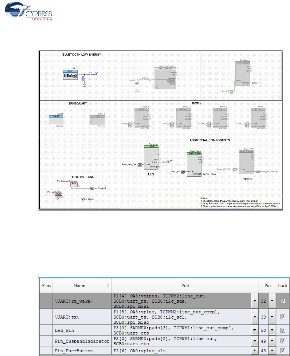
CY8CKIT-042-BLE Bluetooth® Low Energy (BLE) Pioneer Kit Guide, Doc. # 001-93731 Rev. *A 82
Example Projects
Figure 4-64. Top Design for BLE_Dongle_CySmart Project
4.5.2 Hardware Connections
No specific hardware connections are required for this project because all connections are
hardwired on the dongle board.
The pin assignment for this project is in BLE_Dongle_CySmart.cydwr in the Workspace Explorer,
as shown in Figure 4-65.
Figure 4-65. Pin Selection for BLE Dongle Project
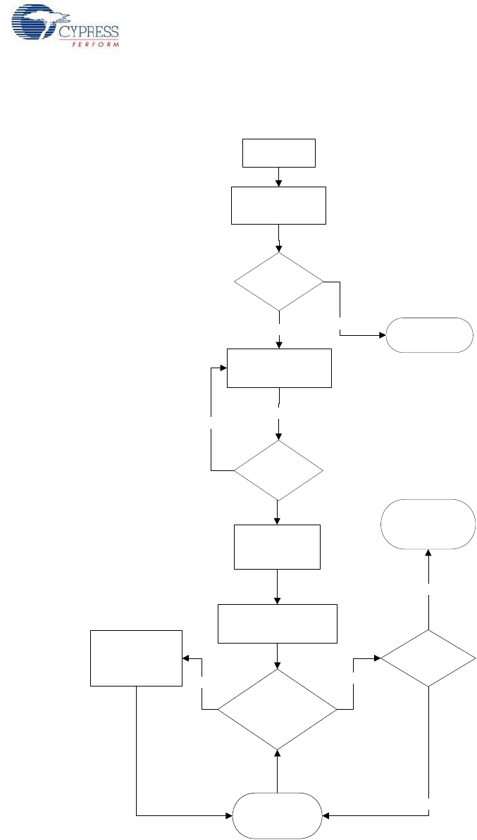
CY8CKIT-042-BLE Bluetooth® Low Energy (BLE) Pioneer Kit Guide, Doc. # 001-93731 Rev. *A 83
Example Projects
4.5.3 Flow Chart
Figure 4-66. Flow Chart for BLE_Dongle_CySmart Project
Perform connect
sequence
Yes
Power BLE
Dongle
Start BLE, Prism and
UART Component
Scan for Capsense
device
Yes
Notification occurs
with valid position
value ?
Yes
Capsense
device found ?
Enter CySmart
emulator mode
CySmart tool
started
Yes
No
No
Enable notifications for
Capsense slider
System in sleep and
waiting for user
button press
USB suspend
triggered ?
No
Update LED
brightness as per
slider position
Wait for slider
position change
notifications
No

CY8CKIT-042-BLE Bluetooth® Low Energy (BLE) Pioneer Kit Guide, Doc. # 001-93731 Rev. *A 84
Example Projects
4.5.4 Verify Output
This project will be used whenever the CySmart PC tool (see CySmart PC Tool on page 160) is
invoked for testing other example projects. In addition, the LED control operation can be verified as
follows.
1. Power the BLE Pioneer kit through the USB connector J13.
2. Program the BLE Pioneer kit with the CapSense and LED example project described in
CapSense Slider and LED on page 47.
3. Connect the BLE dongle to one of the USB ports on the PC.
4. Program the dongle with the BLE_Dongle_CySmart project. See Using Example Projects on
page 42 for programming instructions.
5. Press the user button SW2 on both the BLE dongle and the BLE Pioneer kit. The BLE dongle will
start scanning and the BLE Pioneer kit will start advertising.
6. Wait for the BLE connection between the BLE dongle and the Pioneer baseboard. The connec-
tion success status will be indicated by a 3-second ON state of the red LED followed by the OFF
state on the baseboard.
7. Swipe your finger on the CapSense slider and check the LED brightness variation on the dongle.
4.6 Direct Test Mode (DTM)
4.6.1 Project Description
Bluetooth Core specification (v4.0 and later), Volume 6, Part F defines Direct Test Mode (DTM) as a
method to test the BLE PHY layer and provide a report back to the tester. It uses one of the two
methods, over Host Controller Interface (HCI) or through a two-wire UART interface.
Device under test (DUT) is the BLE system that is to be tested (for example, BLE Pioneer kit). With
DTM, the RF performance of the BLE system can be verified during development or in production
line. The environment consists of the DUT and a tester. The tester has two parts; the upper tester
sends commands through one of the two methods (HCI or two-wire UART) and the lower tester per-
forms the corresponding action over the RF link. The tester compares the command sent over HCI
and the response received over RF, and provides a result of the performance.
Figure 4-67. Direct Test Mode (DTM) Setup
The BLE component allows configuring the device in DTM by enabling the HCI. The appropriate
response to commands from the tester are performed by the BLE stack and does not involve sepa-
rate application handling. The only task is to start the BLE component and call the API to process the
events.
DUT
Upper
Tester
Lower
Tester
RF (2.4 GHz)
HCI/UART
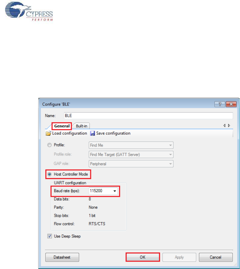
CY8CKIT-042-BLE Bluetooth® Low Energy (BLE) Pioneer Kit Guide, Doc. # 001-93731 Rev. *A 85
Example Projects
The HCI is enabled in the BLE component under the General Settings. Note that when the HCI
mode is selected, all other tabs are hidden and cannot be configured. This is because in HCI mode,
there are no upper layer processes. On enabling HCI mode in the components, the components
automatically reserves a UART block to allow communication between the tester and BLE stack.
The UART exposes the pins that can be assigned in Design Wide Resource > Pins. The only
option to be configured for HCI mode is the baud rate and the pins for communication with the tester.
Figure 4-68. HCI Mode in BLE Component
Many companies develop BLE testers for Direct Test Mode. It is also possible to create PC-based
software tools that will send HCI commands over serial communication links.
For PC-based software, the serial communication link is the COM port, which is enumerated by Kit-
Prog on PSoC 5LP of the BLE Pioneer kit. In such a case, the UART pins in PSoC 4 BLE/PRoC BLE
should be assigned to P1_4 and P1_5. These pins are hardwired to pins on PSoC 5LP and allows
USB-UART data communication between the PC tool and the BLE device.
For separate BLE testers, the serial communication is mostly over the RS232. To test with this
system, an external RS232 voltage translator is required, such as Digilent's Pmod RS232. This
translator will modify the signal level of the serial communication between the BLE device and the
RS232 port on the tester. The UART pins of the BLE device can be assigned to P0_0 and P0_1 and
the header J5 can be used to connect to the RS232 translator.
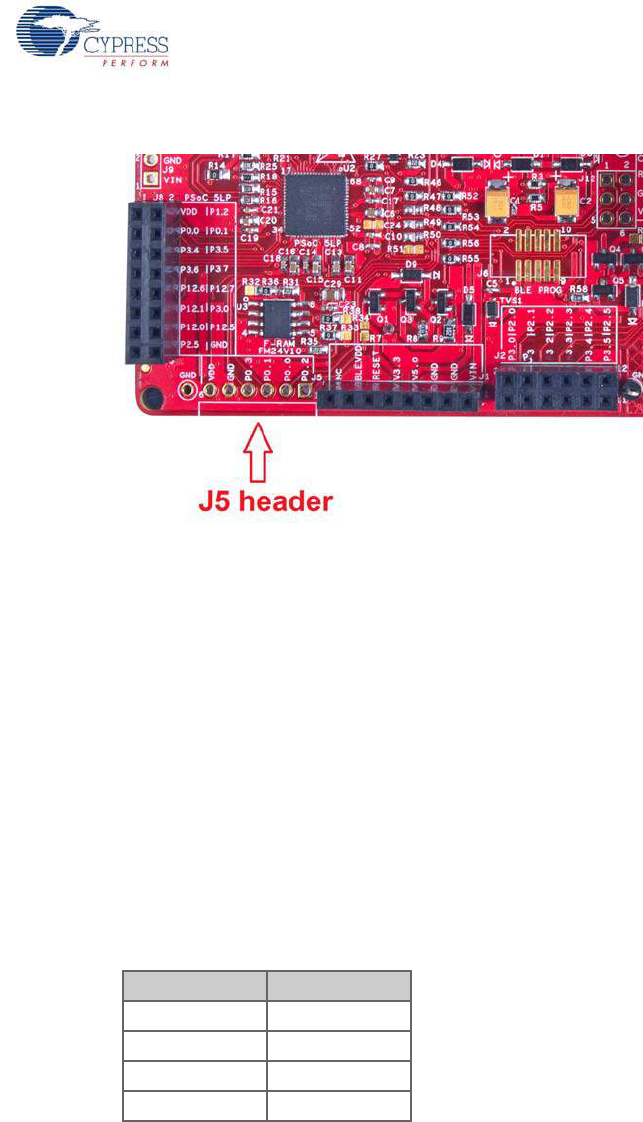
CY8CKIT-042-BLE Bluetooth® Low Energy (BLE) Pioneer Kit Guide, Doc. # 001-93731 Rev. *A 86
Example Projects
Figure 4-69. J5 Header to Interface RS232 Translator
4.6.2 Hardware Connection
For DTM test mode, it is recommended to use SMA connectors and connect the tester and DUT
using a SMA to SMA connector cable. This ensures that there is minimum interference to RF
communication between the DUT and tester, and the performance measured is the true RF
performance of the device. The BLE Pioneer kit module with SMA connector (CY8CKIT-141 PSoC 4
BLE) is available separately and can be ordered from the Cypress web page.
Four UART pins are exposed when HCI mode is selected in the BLE component. These pins should
be assigned to allow communication with the external tester. The connection depends on the tester
being used.
If the tester is a PC-based software and communicated with HCI over serial link, then the onboard
PSoC 5LP on the BLE Pioneer kit can act as the USB-UART bridge. The KitProg on the PSoC 5LP
enumerates as a USB-UART interface and opens a COM port in the PC. This COM port is then used
by the software tool to communicate commands to the BLE device. In this case, the UART pins
should be assigned as follows.
The UART for HCI communication exposes hardware flow control lines CTS and RTS. They can
either be connected to the hardware control lines of the tester or CTS connected to ground for oper-
ation without hardware flow control.
If the tester is an external hardware tester (CBT), then connect any of the RS232 voltage translators
to header J5 on the BLE Pioneer kit. The UART pins should be assigned as follows.
Table 4-3. UART Pin Assignment for PC Software Tester
UART Pins Pin Assigned
RX P1_4
TX P1_5
RTS P1_6
CTS P1_7
CY8CKIT-042-BLE Bluetooth® Low Energy (BLE) Pioneer Kit Guide, Doc. # 001-93731 Rev. *A 87
Example Projects
4.6.3 Verify Output
1. Connect the BLE Pioneer kit through the USB connector J13.
2. Program the BLE Pioneer kit with the PSoC_4_BLE_DTM or PRoC_BLE_DTM project, depend-
ing on the BLE module used (PSoC 4 BLE or PRoC BLE), as described in Using Example Proj-
ects on page 42. Programming should complete successfully.
3. Connect the Serial link, UART or RS232 to the tester.
4. On the software tool for tester, configure the UART communication with the correct COM port and
baud rate, as set in the BLE component.
5. Start the test. The tool will generate the report after the end of the test. This depends on the tes-
ter/tool being used.
Table 4-4. UART Pin Assignment for RS232 Voltage Translator
UART Pins Pin Assigned
RX P0_0
TX P0_1
RTS P0_2
CTS P0_3

CY8CKIT-042-BLE Bluetooth® Low Energy (BLE) Pioneer Kit Guide, Doc. # 001-93731 Rev. *A 88
5. Hardware
This chapter describes the contents of the BLE Pioneer kit hardware and its different blocks, such as
the power block, USB connection, Arduino-compatible headers, BLE module connectors, and
CapSense slider.
5.1 Pioneer Baseboard
5.1.1 PSoC 5LP
An onboard PSoC 5LP is used to program and debug the BLE silicon. The PSoC 5LP connects to
the USB port of the PC through a USB mini-B connector and to the SWD interface of the BLE device.
PSoC 5LP is a true system-level solution providing MCU, memory, analog, and digital peripheral
functions in a single chip. The CY8C58LPxx family offers a modern method of signal acquisition,
signal processing, and control with high accuracy, high bandwidth, and high flexibility. The analog
capability spans the range from thermocouples (near DC voltages) to ultrasonic signals.
For more information, visit the PSoC 5LP web page.
See Serial Interconnection Between PSoC 5LP and BLE Module on page 104 for more details.
5.1.2 Power System
The power supply system on this board is versatile, allowing the input supply to come from the fol-
lowing sources:
■5-V power from onboard USB connector
■5-V to 12-V VIN power from Arduino shield at J1
■3.3 V from I/O header J1
■3 V from CR2032 coin cell
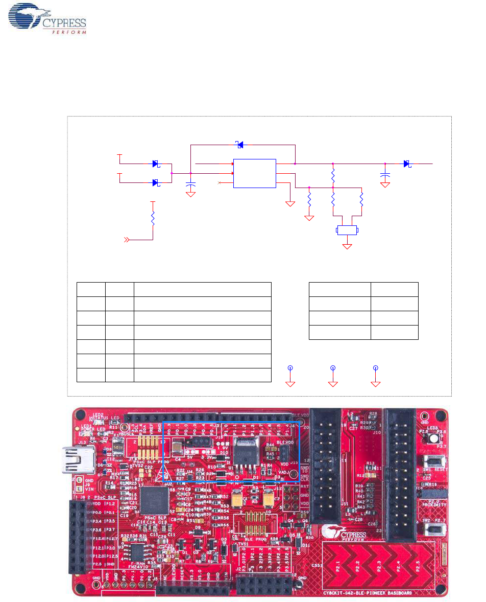
CY8CKIT-042-BLE Bluetooth® Low Energy (BLE) Pioneer Kit Guide, Doc. # 001-93731 Rev. *A 89
Hardware
An adjustable LDO is used to output three different voltage levels (1.9 V, 3.3 V, and 5 V) to power the
BLE module. These voltages are selected with the J16 jumper, as shown in Figure 5-1.
Figure 5-1. Schematics and Board Highlight of LDO and Power Selection Jumper
The input to the LDO can come from either the USB, the VIN pin in the Arduino header J1 or header
J9.
Note: The typical dropout voltage of the selected LDO is 0.3 V at 500-mA output current. This gives
a minimum output of 4.6 V from the input voltage of 5 V from the VBUS. This drop also takes into
account the voltage drop across the Schottky diode connected at the output of the LDO to protect
against voltage applied at the output terminal of the regulator.
VADJ VDD
VCC
EN_CTRL
EN_CTRL
VBUS
VIN
VCC
EN_CTRL
NO LOAD NO LOAD
1
2
3
4
5
6
CTL
VCC
N.C.
OUT
C
GND
Output Voltage ON / OFF control
Power supply voltage input
Unconnected terminal
Voltage output
Output voltage regulation terminal
Ground
Pin No Symbol Function
.
TABLE: LDO PIN FUNCTIONS
GND Test Points
TABLE: VOLTAGE SELECTION JUMPER SETTINGS
JUMPER SETTING O/P VOLTAGE
SHORT 2 & 3
SHORT 1 & 2
REMOVE JUMPER
3.3V
5V
1.9V
TP5
BLACK
SOD123
D1
U1
BA00BC0WFP-E2
VCC
2
CTL
1
NC
3
OUT 4
C5
GND 6
R1
11K
1%
R4
10K 1%
+
3216
C2
4.7uF
R10
10K
R3
14.7K 1%
SOD123
D4
SOD123
D2
TP6
BLACK
R5
4.3K 1%
TP4
BLACK
J16
3 PIN HDR
1
3
2
+
3216
C1
1 uFd
SOD123
D3
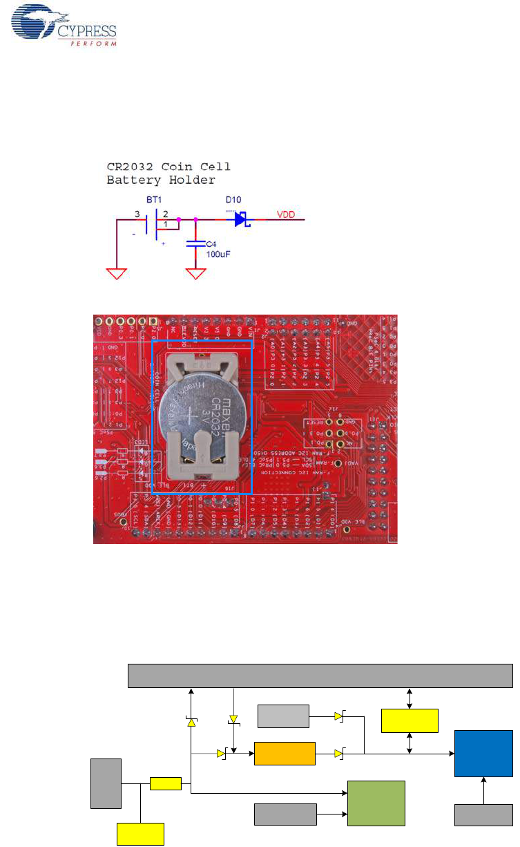
CY8CKIT-042-BLE Bluetooth® Low Energy (BLE) Pioneer Kit Guide, Doc. # 001-93731 Rev. *A 90
Hardware
The board also contains a CR2032 coin cell holder to power the board using a coin cell, as shown in
Figure 5-2.
Figure 5-2. Schematics and Board Highlight of Coin Cell Holder
5.1.2.1 Protection Circuits
The power supply rail has reverse-voltage, overvoltage, short circuits, and excess current protection
features, as shown in Figure 5-3.
Figure 5-3. Power Supply Block Diagram With Protection Circuits
■A PTC resettable fuse is connected to protect the computer's USB ports from shorts and
overcurrent.
■ORing diodes prevent damage to components when the board is powered from different voltage
sources at the same time.
■ESD protection is provided for the USB mini-B connector.
I/OHeader
USB
Bluetooth
Module
5V Vin 3.3V
PSoC 5LP
5V
PSoC 5LP 10 Pin
Prog. Header
PTC
LDO
ESD
Protection
MOSFET based
Protection Ckt
Coin cell
Battery Holder
PSoC 4 BLE 10
Pin Prog. Header
~3V
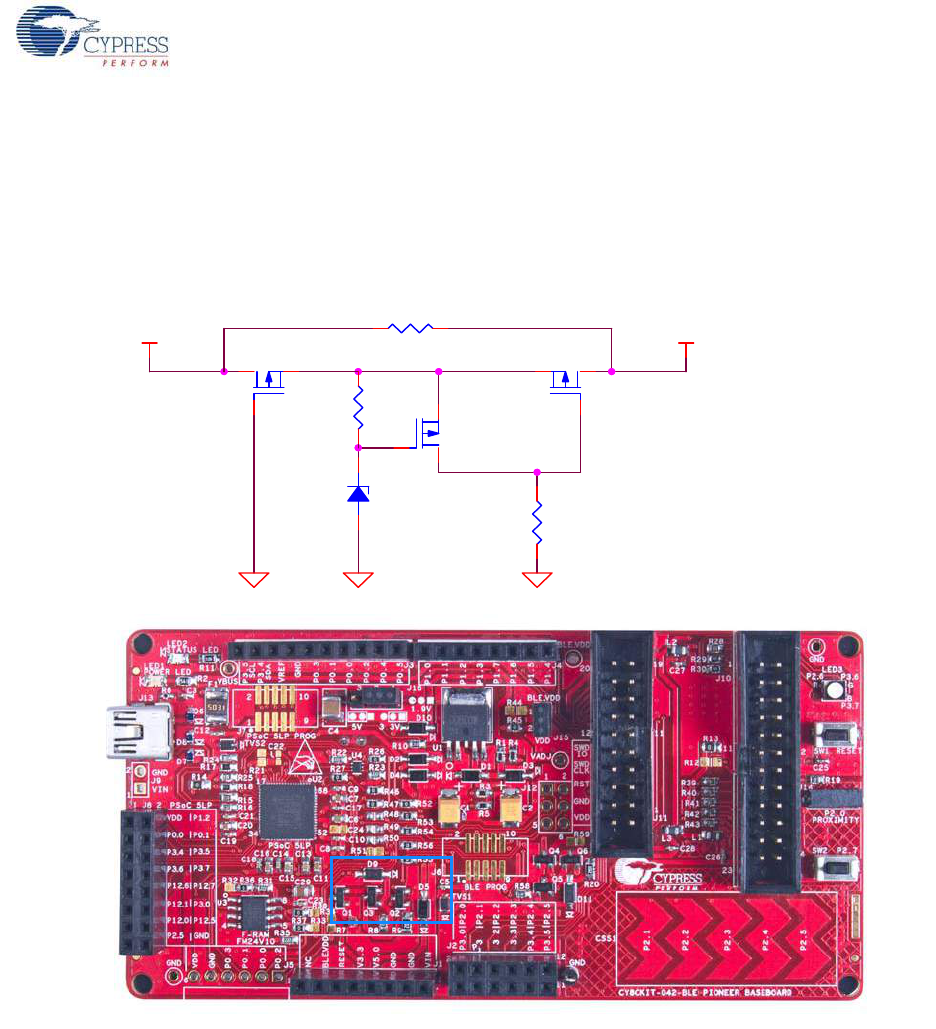
CY8CKIT-042-BLE Bluetooth® Low Energy (BLE) Pioneer Kit Guide, Doc. # 001-93731 Rev. *A 91
Hardware
■A MOSFET-based protection circuit is provided for overvoltage and reverse-voltage protection for
the 3.3-V rail from J1.5, as shown in Figure 5-4. When a voltage greater than 3.6 V is applied
from J1.5, the Q2 PMOS will turn off, which will cut off the power to the BLE module from J1.5.
When reverse voltage is applied from J1.5, the Q1 PMOS will turn off, protecting the onboard
components from reverse voltage.
Figure 5-4. Schematics and Board Highlight of MOSFET Protection Circuit for 3.3-V Input
VDDV3.3
NO LOAD
R9
10K
R8
15K
Q2
PMOS( NTR4171PT1G)
R7 ZERO
D9
Vz=3.9V(BZT52C3V9-7-F)
Q3
PMOS(PMV48XP,215)
Q1
PMOS( DMP3098L-7)
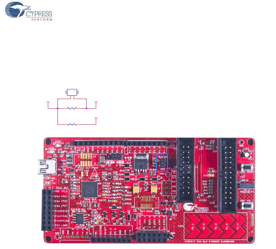
CY8CKIT-042-BLE Bluetooth® Low Energy (BLE) Pioneer Kit Guide, Doc. # 001-93731 Rev. *A 92
Hardware
5.1.2.2 Current Measurement Jumper
To demonstrate the low power consumption of PSoC 4/PRoC BLE, a two-pin header is populated in
series with the power supply to the PSoC 4 BLE. This can be used to measure current using an
ammeter without the need to desolder any components from the board, as shown in Figure 5-5.
Figure 5-5. Schematics and Board Highlight of Current Measurement Jumper
NO LOAD
VDD BLE_VDD
VTARG
J15 HDR2
1
2
0805
R44 ZERO
0603
R45 ZERO
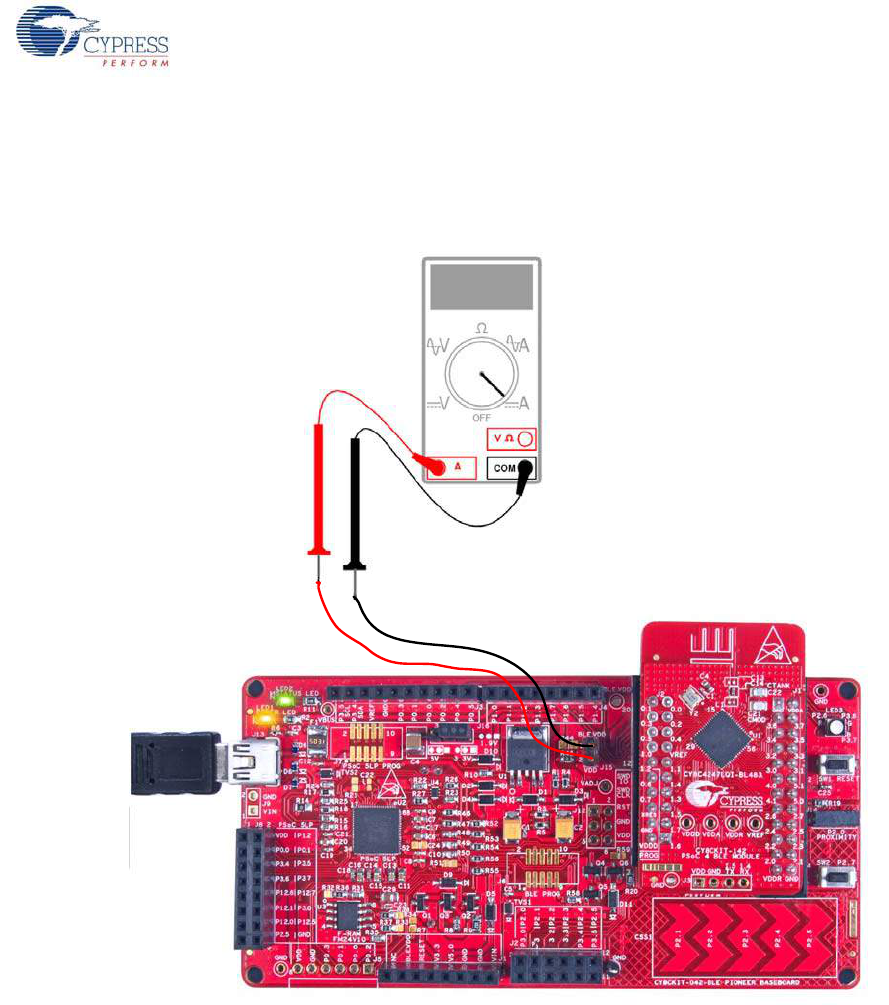
CY8CKIT-042-BLE Bluetooth® Low Energy (BLE) Pioneer Kit Guide, Doc. # 001-93731 Rev. *A 93
Hardware
The following methods are supported for measuring the current consumption of the BLE device.
■When the board is powered through the USB port (J13), remove jumper J15 and connect an
ammeter, as shown in Figure 5-6.
Figure 5-6. Current Measurement when Powered from USB Port
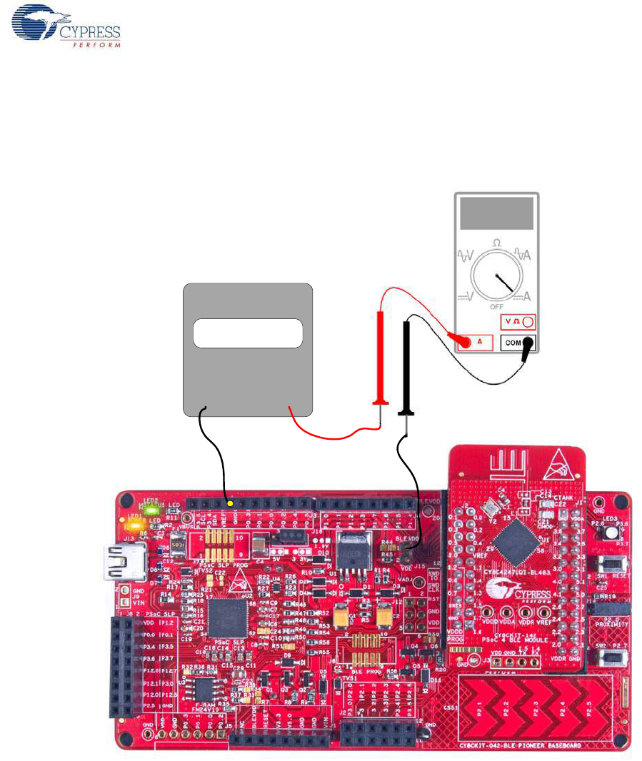
CY8CKIT-042-BLE Bluetooth® Low Energy (BLE) Pioneer Kit Guide, Doc. # 001-93731 Rev. *A 94
Hardware
■When the board is powered from an external voltage supply, remove the USB port (J13). Connect
the positive terminal of the external voltage supply to the positive terminal of the ammeter and the
negative terminal of the ammeter to the upper pin of J15. Connect the negative terminal of the
external voltage supply to and GND pin on board. Figure 5-7 shows the required connections.
Figure 5-7. Current Measurement when Powered Separately
5.1.3 Programming Interface
The kit allows you to program and debug the PSoC 4 BLE/PRoC BLE in two ways:
■Using the onboard PSoC 5LP Programmer and Debugger
■Using a CY8CKIT-002 MiniProg3 Programmer and Debugger
VOLTAGE
SOURCE
- +
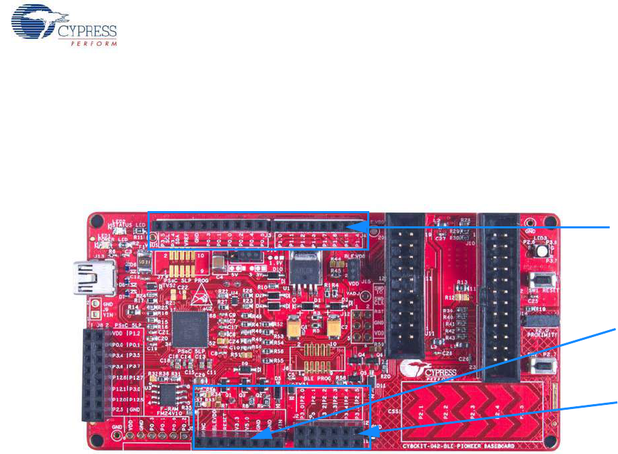
CY8CKIT-042-BLE Bluetooth® Low Energy (BLE) Pioneer Kit Guide, Doc. # 001-93731 Rev. *A 95
Hardware
5.1.4 Expansion Connectors
5.1.4.1 Arduino Compatible Headers (J1, J2, J3, J4, and J12-unpopulated)
This kit has five Arduino compatible headers: J1, J2, J3, J4, and J12, as shown in Figure 5-8. You
can develop applications based on the Arduino shield's hardware.
Figure 5-8. Arduino Headers
The J1 header contains I/O pins for reset, I/O reference voltage (IOREF), and power supply line. The
J2 header is an analog port that contains I/O pins for SAR ADC, comparator, and opamp. The J3
header is primarily a digital port that contains I/O pins for PWM, I2C, SPI, and analog reference. The
J4 header is also a digital port that contains I/O pins for UART and PWM. The J12 header is an
Arduino ICSP compatible header for the SPI interface and is not populated. Refer to the “No Load
Components” section of Bill of Materials (BOM) on page 184 for the header part number.
Additional Functionality of Header J2
The J2 header is a 6×2 header that supports Arduino shields. The Port 2 and Port 3 pins of PSoC 4
BLE and PRoC BLE are brought to this header. The Port 2 pins also connect to the onboard
CapSense slider through 560-ohm resistors. When the CapSense feature is not used, remove these
resistors to help ensure better performance with these pins.
Arduino
compatible
I/O header
(J3/J4)
Arduino
compatible
I/O header
(J3/J4)
Arduino
compatible
I/O header
(J2)
Arduino
compatible
power
header (J1)
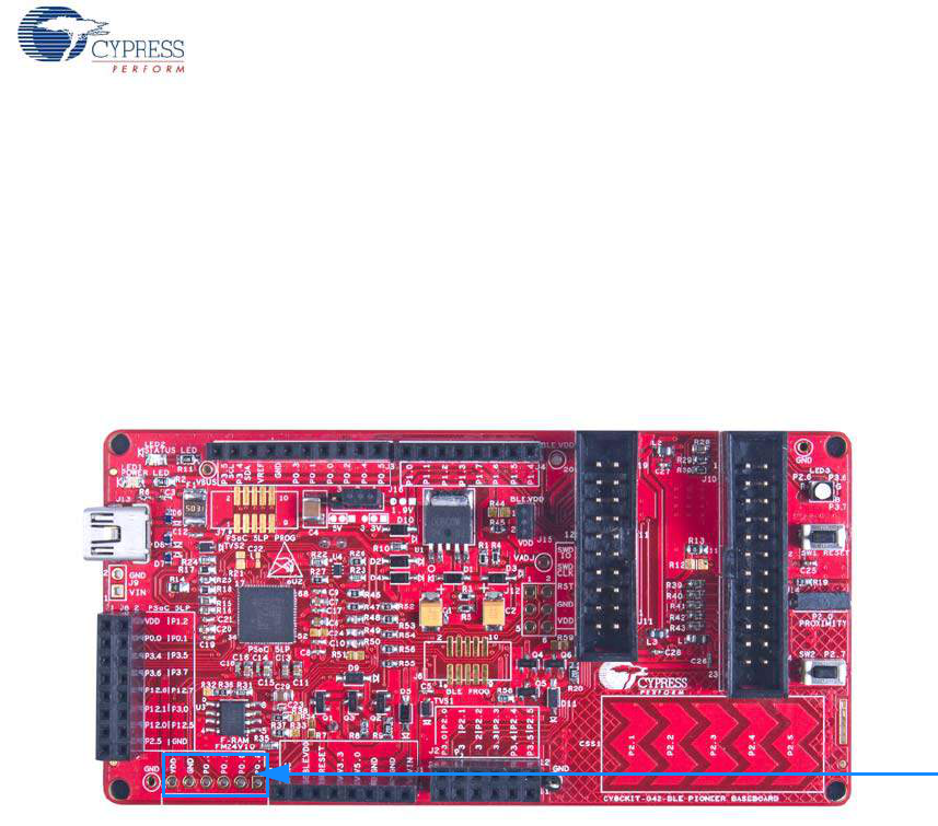
CY8CKIT-042-BLE Bluetooth® Low Energy (BLE) Pioneer Kit Guide, Doc. # 001-93731 Rev. *A 96
Hardware
5.1.4.2 PMod Connector - Digilent Pmod Compatible (J5-unpopulated)
This port supports Digilent Pmod peripheral modules (see Figure 5-9). Pmods are small I/O
interfaces that connect with the embedded control boards through either 6- or 12-pin connectors.
The BLE Pioneer kit supports the 6-pin Pmod type 2 (SPI) interface. For Digilent Pmod cards, go to
www.digilentinc.com.
This header is not populated on the BLE Pioneer board. You must populate this header before
connecting the Pmod daughter cards. Refer to the “No Load Components” section of Bill of Materials
(BOM) on page 184 for the header part number.
Figure 5-9. Schematics and Board Highlight of PMod Connector
Digilent®
PmodTM -
compatible I/O
header (J5)
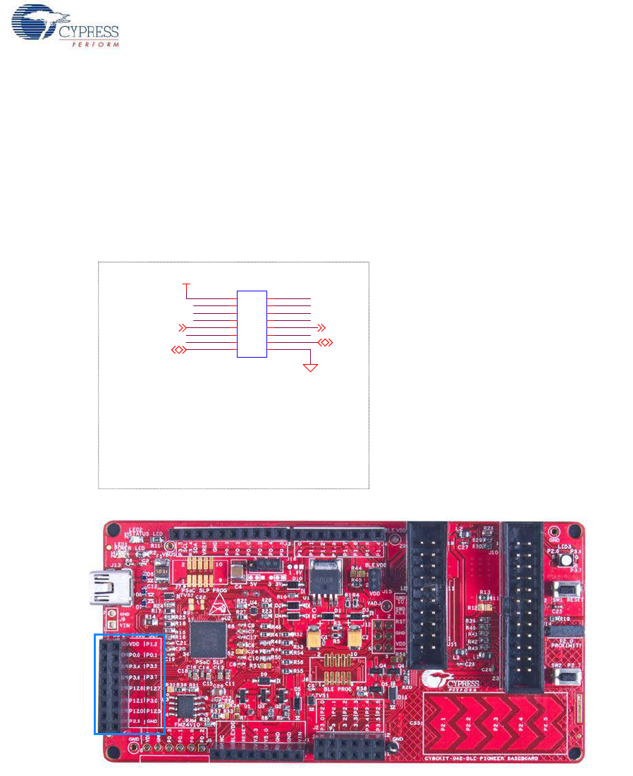
CY8CKIT-042-BLE Bluetooth® Low Energy (BLE) Pioneer Kit Guide, Doc. # 001-93731 Rev. *A 97
Hardware
5.1.4.3 PSoC 5LP GPIO Header (J8)
An 8×2 header is provided on the board to pull out several pins of PSoC 5LP to support advanced
features such as a low-speed oscilloscope and a low-speed digital logic analyzer (see Figure 5-10).
This header also contains the USB-Serial bridge pins that can be used when these pins are not
accessible on the Arduino headers because a shield is connected.
Note: You can use PSoC 5LP for your own custom firmware. See Developing Applications for PSoC
5LP on page 134 for details.
Figure 5-10. Schematics and Board Highlight of PSoC 5LP GPIO Expansion Header
PSoC 5LP GPIO Expansion Header
USB-Serial Bridge Connections
P5LP12_6 ------------- UART RX
P5LP12_7 ------------- UART TX
P5LP12_0 ------------- SPI SCLK / I2C SCL
P5LP12_1 ------------- SPI MISO / I2C SDA
P5LP12_5 ------------- SPI MOSI
P5LP2_5 ------------- SPI SSEL
P5LP12_7P5LP12_6
P5LP3_6 P5LP3_7
P5LP0_0 P5LP1_2
P5LP3_5P5LP3_4
P5LP3_0
P5LP0_1
P5LP12_1 P5LP12_5P5LP12_0
P5LP2_5
VDD
SPI_MOSI
SPI_SSEL
UART TXUART RX
J8
8x2 RECPT
1
122
3
344
5
566
7
788
10 10
9
9
12 12
11
11
14 14
13
13
16 16
15
15
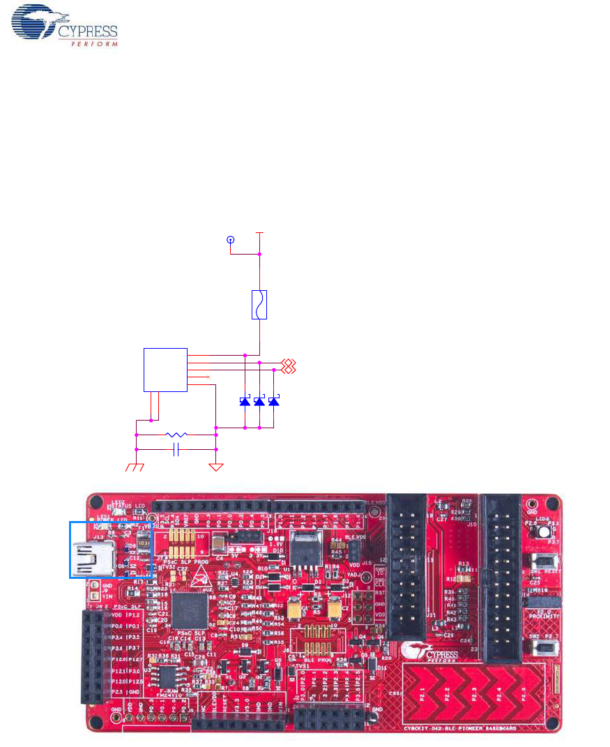
CY8CKIT-042-BLE Bluetooth® Low Energy (BLE) Pioneer Kit Guide, Doc. # 001-93731 Rev. *A 98
Hardware
5.1.5 USB Mini-B Connector
The PSoC 5LP connects to the USB port of a PC through a mini-B connector (see Figure 5-11),
which can also be used to power the board. A resettable polyfuse is used to protect the computer's
USB ports from shorts and overcurrent. If more than 500 mA is drawn from the USB port, the fuse
will automatically break the connection until the short or overload is removed.
Figure 5-11. Schematics and Board Highlight of USB Mini-B Connector
NO LOAD
DP
DM
VBUS
P5LP_DM
P5LP_DP
J13
USB MINI B
VBUS 1
DM 2
DP 3
GND 5
ID 4
S1
6S2
7
F1
PTC Resettable Fuse
1 2
0603
D6
0402
R6100K
0603
D8
0402
C3 0.01 uF
TP2 RED
0603
D7
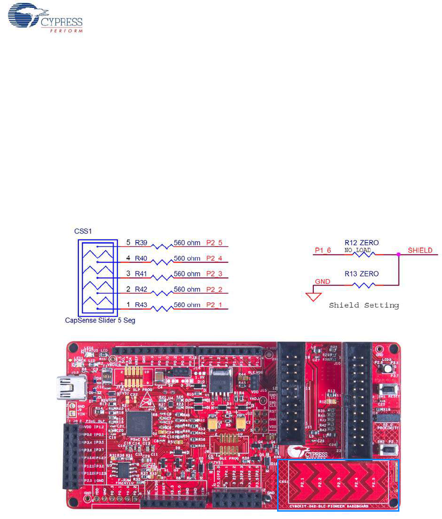
CY8CKIT-042-BLE Bluetooth® Low Energy (BLE) Pioneer Kit Guide, Doc. # 001-93731 Rev. *A 99
Hardware
5.1.6 CapSense Circuit
5.1.6.1 CapSense Slider
The kit has a five-segment linear capacitive touch slider, which is connected to the BLE module pins
(see Figure 5-12). The CMOD and CTANK capacitors are required for CapSense functionality and
are provided on the BLE modules (see BLE Module Board on page 106). A 2.2-nF capacitor is
present on the CMOD pin, P4[0], for CapSense operation. This kit also supports CapSense designs
that enable waterproofing. On this kit, the connection of the shield to the pin or to ground is made by
resistors R12 and R13, respectively. By default, R13 is mounted on the board, which connects the
shield to ground. Populate R12 and remove R13 when evaluating waterproofing designs, which will
connect the shield to the designated pin, P1[6].
Figure 5-12. Schematics and Board Highlight of CapSense Slider and Shield Setting
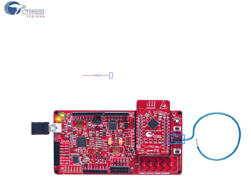
CY8CKIT-042-BLE Bluetooth® Low Energy (BLE) Pioneer Kit Guide, Doc. # 001-93731 Rev. *A 100
Hardware
Proximity Header
The baseboard contains a header (J14) for CapSense proximity wire connection (see Figure 5-13).
Figure 5-13. Schematics and Board Highlight of Proximity Header
Proximity Header
P0_2
P0_0
P0_1
P0_3 P2_0
VDD
J14
1x1 RECP
CON6
SS 1
MOSI 2
MISO 3
SCK 4
GND 5
VCC 6
0603
R19 ZERO
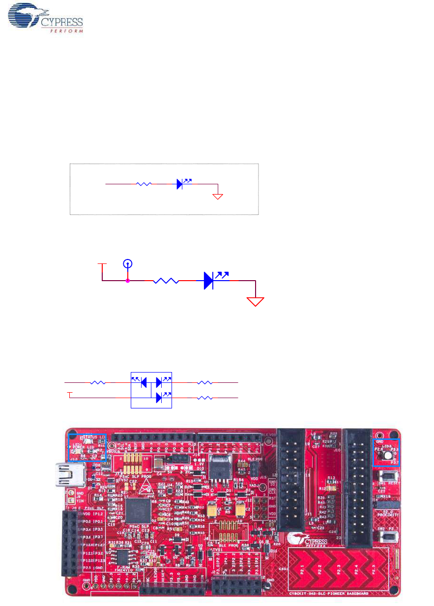
CY8CKIT-042-BLE Bluetooth® Low Energy (BLE) Pioneer Kit Guide, Doc. # 001-93731 Rev. *A 101
Hardware
5.1.7 Pioneer Board LEDs
The Pioneer board has three LEDs. A green LED (LED2) indicates the status of the programmer. An
amber LED (LED1) indicates the status of power supplied to the board. The kit also has a
general-purpose tricolor LED (LED3) for user applications. These are connected to P2_6 (Red LED),
P3_6 (Green LED) and P3_7 (Blue LED). Figure 5-14 and Figure 5-15 show the schematics of these
LEDs.
Figure 5-14. Schematics of Status and Power LED
Figure 5-15. Schematics and Board Highlight of RGB LED
Status LED
P5LP3_1
0805
R11
820 ohm
0805
LED2
Status LED Green
2 1
VADJ
NO LOAD
R2
560 ohm
TP1 RED
0805
LED1
Power LED
2 1
P3_6
P3_7
P2_6
BLE_VDD R30 1.5K
R28 2.2K R29 1.5K
RG
B
LED3
RGB LED
1
2 3
4
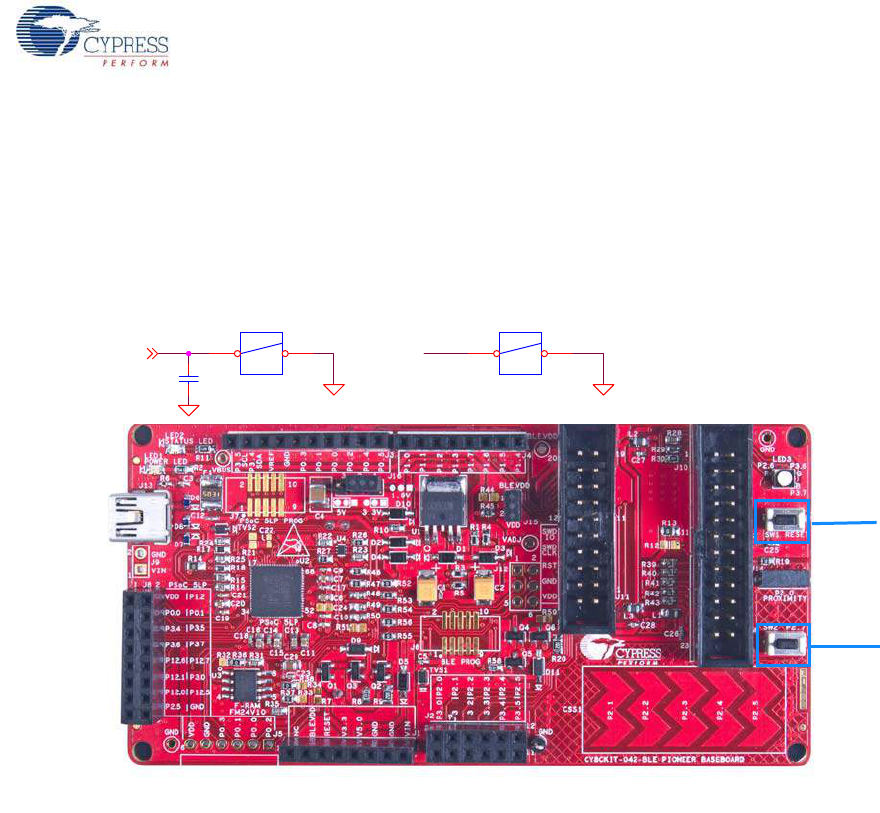
CY8CKIT-042-BLE Bluetooth® Low Energy (BLE) Pioneer Kit Guide, Doc. # 001-93731 Rev. *A 102
Hardware
5.1.8 Push Buttons
The board contains a reset push button and a user push button, as shown in Figure 5-16. The reset
button is connected to the XRES pin of BLE and is used to reset the BLE device. The user button is
connected to P2[7] of the BLE device. Both the push buttons connect to ground on activation (active
low).
Figure 5-16. Schematics and Board Highlight of Reset Button and User Push Button
RESET USER SWITCH
P2_7/XRES
/XRES
0402
C25
0.1 uF
SW2
EVQ-PE105K
1 2
SW1
EVQ-PE105K
1 2
RESET (SW1)
User Button
(SW2)
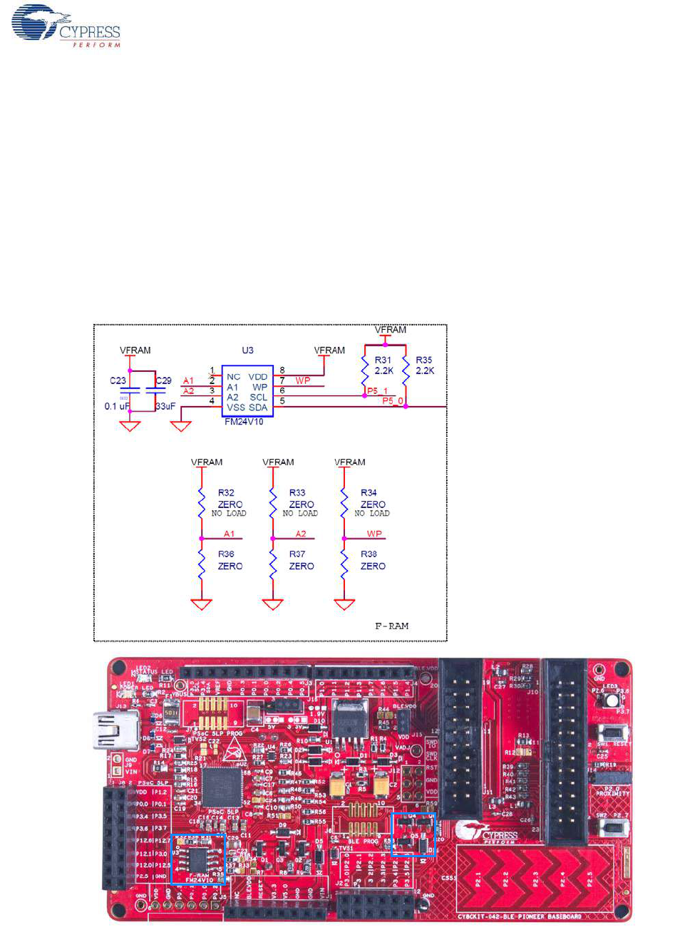
CY8CKIT-042-BLE Bluetooth® Low Energy (BLE) Pioneer Kit Guide, Doc. # 001-93731 Rev. *A 103
Hardware
5.1.9 Cypress Ferroelectric RAM (F-RAM)
The baseboard contains an F-RAM device (FM24V10) (see Figure 5-17) that can be accessed
through I2C lines P5[0] and P5[1] of the PSoC 4 BLE/PRoC BLE device. The F-RAM is 1-Mbit
(128 KB) with an I2C speed up to 1 Mbps. The I2C slave address of the F-RAM device is seven bits
wide, and the LSB two bits are configurable through physical pins and are hardwired to 00 on the
board. By default, the address of the F-RAM device used on the board is 0x50. This address can be
modified by changing the R32/R36 and R33/R37 pairs. The operating voltage range of the F-RAM is
between 2 V and 3.6 V. To prevent the application of 5 V from the adjustable LDO regulator on the
board, a MOSFET based protection circuit similar to the one used for the 3.3-V rail is connected
between the output of the regulator and the VDD pin of the F-RAM. The protection circuit cuts off the
power to the F-RAM when the output of the regulator is greater than 3.6 V.
Figure 5-17. Schematics and Board Highlight of F-RAM
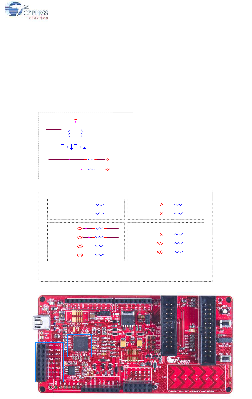
CY8CKIT-042-BLE Bluetooth® Low Energy (BLE) Pioneer Kit Guide, Doc. # 001-93731 Rev. *A 104
Hardware
5.1.10 Serial Interconnection Between PSoC 5LP and BLE Module
The PSoC 5LP onboard programmer is also a USB-Serial interface, It supports USB-UART and
USB-I2C bridges (see Figure 5-18). The pull-ups resistors on I2C bus are enabled when the protocol
is selected from user interface (like bridge control panel). The USB-Serial pins of the PSoC 5LP are
also available on the Arduino header; therefore, the PSoC 5LP can be used to control Arduino
shields with the SPI/I2C/UART interface. Refer Using PSoC 5LP as USB-UART Bridge on page 115
and Using PSoC 5LP as USB-I2C Bridge on page 126 for more information on how to use these
serial interconnections
Figure 5-18. Schematics and Board Highlight of Serial Interface and I2C Pull-Up via FET
I2C Connection
SCL
SDA
P5LP12_0
P5LP12_1
P5LP2_7
P5LP2_6
VDD
SPI_MISO / I2C_SDA
SPI_SCLK / I2C_SCL
R22
2.2K R23
2.2K
U4
NTZD3152P
6
2
1
3 4
5
R26 ZERO
R27 ZERO
NO LOAD
USB-I2C
USB-SPI
USB-UART
USB-SWD
PSoC 5LP and PSoC 4 BLE/PRoC BLE Connections
NO LOAD
NO LOAD
NO LOAD
P0_3
P0_1
P0_2
P0_0
P3_5
P3_4
/XRES
P0_7
P0_6
P1_5
P1_4
SPI_MOSI
SPI_SSEL
SPI_MISO / I2C_SDA
SPI_SCLK / I2C_SCL
RESET
SWDIO
SWDCLK
UART TX
UART RX
R46 ZERO
R47 ZERO
R54 ZERO
R51 ZERO R56 ZERO
R50 ZERO R55 ZERO
R52 ZERO
R48 ZERO
R49 ZERO
R53 ZERO
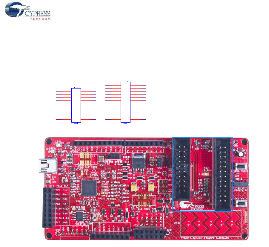
CY8CKIT-042-BLE Bluetooth® Low Energy (BLE) Pioneer Kit Guide, Doc. # 001-93731 Rev. *A 105
Hardware
5.1.11 Bluetooth Module Headers
The PSoC 4 BLE and PRoC BLE Modules are connected to the Pioneer board using the two (24-pin
and 20-pin) Bluetooth module headers, as shown in Figure 5-19.
Figure 5-19. Schematics and Board Highlight of Bluetooth Module Headers
For information on how to add these on your own board refer to Adding BLE module compatible
headers on your own baseboard on page 195.
Analog PinsDigital Pins
VDDA
P3_7P3_6 P3_5P3_4 P3_3P3_2 P3_1P3_0 P5_1P4_0 P5_0P4_1 P2_7P2_6 P2_5P2_4 P2_3P2_2 P2_1P2_0 GNDVDDR
GND
VDDD
P1_7
P1_5
P1_3
P0_5
P0_3
P0_1
P0_4
P0_2
P0_0
P1_6
/XRES
P1_0
P1_1 P1_2
P1_4 P0_7
P0_6
VREF
GND
J11
HEADER 10x2
1 2
3 4
5 6
7 8
910
11 12
13 14
15 16
17 18
19 20
J10
HEADER 12x2
1 2
3 4
5 6
7 8
910
11 12
13 14
15 16
17 18
19 20
21 22
23 24