D Link 2002020009-1 5 GHz Wireless Access Point User Manual Users manual
D Link Corporation 5 GHz Wireless Access Point Users manual
D Link >
Contents
- 1. Users manual
- 2. Revised users manual
Users manual

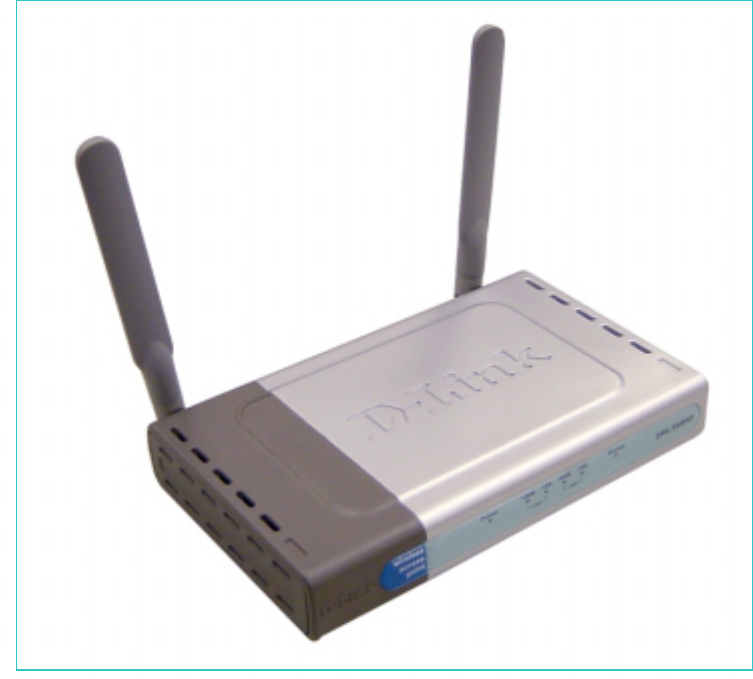
D-Link AirPro DWL-5000AP
DWL-5000APDWL-5000AP
DWL-5000AP
5 GHz Wireless Access Point
Manual
Rev. 042202
Building Networks for People

2
Contents
Package Contents ....................................................3
Introduction...............................................................5
Wireless Basics ........................................................8
Getting Started........................................................12
Using the Configuration Utility ................................16
Troubleshooting ......................................................25
Networking Basics ..................................................32
Technical Specifications..........................................60
Contacting Technical Support .................................62
Limited Warranty and Registration..........................63
Package Contents
Contents of Package:
• D-Link AirPro DWL-5000AP 5GHz Wireless Access Point
• Power Cable
• Power Supply – 3.3V DC, 2.6A
• Manual on CD
• Printed Quick Installation Guide
Note: Using a power supply with a different voltage rating than the one included with
the DWL-5000AP will cause damage and void the warranty for this product.
If any of the above items are missing, please contact your reseller.
System Requirements:
4
• Computer with a Windows or Macintosh or Linux based operating
system with an installed Ethernet adapter.
• Internet Explorer or Netscape Navigator, version 4.0 or above, with
JavaScript enabled.
Introduction
The D-Link AirPro DWL-5000AP Wireless Access Point is an IEEE 802.11a
compatible, high performance, wireless access point that supports data
transfer speeds of up to 108 Mbps in Turbo Mode.
It is an ideal way to extend the reach and number of computers connected to
your wireless network. After completing the steps outlined in the Quick
Installation Guide (included in your package) you will have the ability to
share information and resources, such as files and printers, and take full
advantage of a “connected” environment for work or play! Please take a
look at our Getting Started section in this manual. You will see several
options for setting up a network using the DWL-5000AP.
The DWL-5000AP is compatible with most popular operating systems,
including Macintosh, Linux and Windows, and can be integrated into a large
network. This Manual is designed to help you connect the Access Point and
the D-Link AirPro 802.11a Wireless Adapters into a network in Infrastructure
mode. The IEEE 802.11a standards compliance means that the DWL-
5000AP gives you the flexibility to connect to any 802.11a network.
This manual provides a quick introduction to wireless technology and its
application as it relates to networking. Take a moment to read through this
manual and get acquainted with wireless technology.
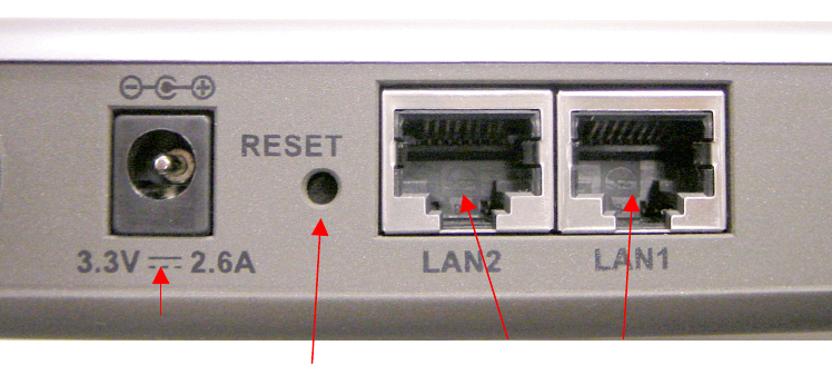
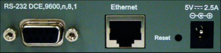
Connections
Ethernet Port
• Straight-through cable is required
when connecting to a router or switch
• Cross-over cable when connect to a
computer
Reset button
Power inlet

6
Product Features
• Adheres to 802.11a standard in providing high data wireless transfer
rates of up to 54 Mbps. Capable of providing data rates of up to 108
Mbps in Turbo Mode.
• Web-based interface for Managing and Configuring
• Eight non-overlapping Channels available to users
• Operation in the 5.15 to 5.35 and 5.725 to 5.85 GHz frequency band
• Orthogonal Frequency Division Multiplexing (OFDM) – a new
technique for transmitting high-speed data over a radio wave.
• Dynamic data rate scaling from 6, 9, 12, 18, 24, 36, 48, 54 and
108Mbps depending upon reception quality.
• Maximum reliability, throughput and connectivity with automatic data
rate switching.
• Supports Wired Equivalent Privacy (WEP) data encryption at
64/128/152-bit encryption with dynamic key exchange for security.
• Two external antennas
LEDS
LED stands for Light-Emitting Diode. The DWL-5000AP Wireless Access
Point has 6 LEDs as shown below:
10M LAN1 Flashes steadily to indicate
connection; intermittent flashes
indicate activity at 10Mbps
100M LAN1 Flashes steadily to indicate
connection; intermittent flashes
indicate activity at 100Mbps
LED LED Activity
Power Steady light indicates a connection
to a power source

10M LAN 2 Flashes steadily to indicate
connection; intermittent flashes
indicate activity at 10Mbps
100M LAN 2 Flashes steadily to indicate
connection; intermittent flashes
indicate activity at 100Mbps
Wireless Flashes steadily to indicate a
wireless connection
8
Wireless Basics
D-Link AirPro wireless products are based on industry standards to provide
easy-to-use and compatible high-speed wireless connectivity within your
home or business. Strictly adhering to IEEE 802.11a, the D-Link AirPro
wireless family of products will allow you to access the data you want, when
and where you want it. No longer will you be limited to one location or forced
to run new wiring through your home or office. You will be able to enjoy the
freedom that wireless networking delivers.
A wireless LAN (WLAN) is a cellular computer network that transmits and
receives data with radio signals instead of wires. Wireless LANs are used
increasingly in both home and office environments. Innovative ways to utilize
WLAN technology are helping people to work and communicate more
efficiently. Increased mobility and the absence of cabling and other fixed
infrastructure have proven to be beneficial for many users.
Wireless users can use the same network applications they use on an
Ethernet LAN. Wireless adapter cards used on laptop and desktop systems,
support the same protocols as Ethernet adapter cards. For most users, there
is no noticeable functional difference between a wired Ethernet desktop
computer and a wireless computer equipped with a wireless adapter other
than the added benefit of the ability to roam within the wireless-cell. Under
many circumstances, it may be desirable for mobile network devices to link
to a conventional Ethernet LAN in order to use servers, printers or an
Internet connection supplied through the wired LAN. A Wireless Access
Point (AP) is a device used to provide this link.
People use wireless LAN technology for many different purposes.
Mobility - Productivity increases when people have access to data in any
location within the operating range of the WLAN. Ad-hoc management
decisions based on real-time information can significantly improve worker
efficiency.
Low Implementation Costs - WLANs are easy to set up, manage, change
and relocate. Networks that frequently change, both physically and logically,
can benefit from WLANs ease of implementation. WLANs can operate in
locations where installation of wiring may be impractical. Furthermore, IEEE
standardization mandates interoperability of all WLAN devices that conform
to the 802.11a set of standards.
Installation Speed and Simplicity - Installing a wireless LAN system can
be fast and easy and can eliminate the need to pull cable through walls and
ceilings.
Wireless Basics (continued)
Installation Flexibility - Wireless technology allows the network to go where
wires cannot go.
Reduced Cost-of-Ownership - While the initial investment required for
wireless LAN hardware might be higher than the cost of wired LAN hardware,
overall installation expenses and life-cycle costs will be significantly lower.
Long-term cost benefits are greatest in dynamic environments requiring
frequent moves, adds, and changes.
Scalability - Wireless LAN systems can be configured in a variety of
topologies to meet the needs of specific applications and installations.
Configurations are easily changed and range from peer-to-peer networks
suitable for a small number of users to full infrastructure networks of
thousands of users that allow roaming over a broad area.
D-Link AirPro Wireless LAN products include:
802.11a 5GHz Wireless Cardbus Adapters used with laptop
computers (DWL-A650)
802.11a 5GHz Wireless PCI cards used with desktop computers
(DWL-A520)
802.11a 5GHz Wireless Access Points (DWL-5000AP)
Standards - Based Technology
The IEEE 802.11a standard designates that devices operate at an optimal
data rate of 54 Megabits per second. This means you will be able to transfer
large files quickly or even watch a movie in MPEG format over your network
without noticeable delays. This technology works by transmitting high-speed
digital data over a radio wave utilizing OFDM (Orthogonal Frequency
Division Multiplexing) technology. OFDM works by splitting the radio signal
into multiple smaller sub-signals that are then transmitted simultaneously at
different frequencies to the receiver. OFDM reduces the amount of
crosstalk (interference) in signal transmissions. D-Link AirPro products will
automatically sense the best possible connection speed to ensure the
greatest speed and range possible with the technology.
10
Wireless Basics (continued)
Installation Considerations
Designed to go up to 900 feet (~300 meters), D-Link AirPro DWL-5000AP
lets you access your network with your laptop computer from virtually
anywhere you want. Keep in mind, however, that the number and thickness
of walls, ceilings or other objects that the wireless signals must pass thru
may limit range. Typical ranges vary depending on the types of materials
and background RF noise in your home or business. The key to maximizing
range is to follow these basic principles:
1. Keep the number of walls and ceilings between the Access Point and
your receiving device to a minimum - Each wall or ceiling can reduce
your D-Link AirPro Wireless product’s range from 3-90 feet (1-30 meters.)
For some businesses or for a large residential home deployment, it may
be beneficial to have more than one access point with overlapping
coverage.
2. Be aware of the direct line between Access Points and computers with
wireless adapters - A wall that is 1.5 feet thick (.5 meters), at a 45-
degree angle appears to be almost 3 feet (1 meter) thick. At a 2-degree
angle it looks over 42 feet (14 meters) thick! Try to make sure that the
Access Points and Adapters are positioned so that the signal will travel
straight through a wall or ceiling for better reception.
3. Building Materials make a difference - A solid metal door or aluminum
studs may have a negative effect on range. Try to position Access Points,
and computers with wireless adapters so that the signal passes through
drywall or open doorways and not other materials.
4. Make sure that the antenna is positioned for best reception by using the
software signal strength tools included with your product.
5. Keep your product away (at least 3-6 feet or 1-2 meters) from electrical
devices or appliances that generate extreme RF noise.
Wireless Basics (continued)
For the average residence, range should not be a problem. If you
experience low or no signal strength in areas of your home that you wish to
access, consider positioning the Access Point in a location directly between
the computers with wireless adapters that will be connected. Additional
Access Points can be connected to provide better coverage in rooms where
the signal does not appear as strong as desired.
Using radio frequency (RF) technology, WLANs (Wireless Local Area
Networks) transmit and receive data over the air, minimizing the need for
wired connections. Thus, WLANs combine data connectivity with user
mobility, and, through simplified configuration, enable movable LANs.
12
Getting Started
To begin, select the type of wireless network you will be building.
We will discuss the following types of networks in this section:
1. A Home Internet Network
with A Residential Gateway/Router
2. A Home Internet Network with Multiple IP Addresses
Please select, from the two types of networks described above, the type of
network that is appropriate for your needs. Please follow the instructions in
the corresponding section that follows.
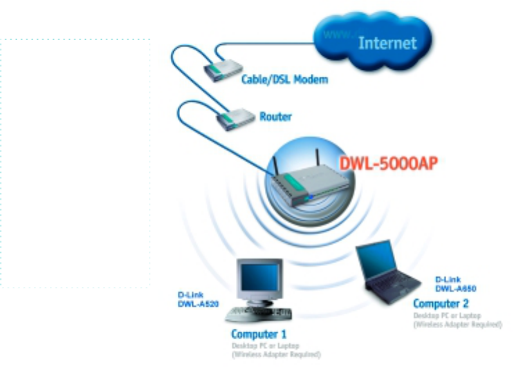
1. A Home Internet Network with A Residential Gateway/Router
(Network administrators with Dynamic IPs can also follow these instructions.)
If you have two or more computers (laptops or desktops) and want to share
files, printers, and Internet access using a DHCP-capable Residential
Gateway/Router – or - if you want to connect to an Ethernet network that
uses Dynamic (DHCP) IP addresses, then follow the instructions on the next
page. When it is complete, your network may look similar to this:
DHCP stands for
Dynamic Host
Configuration
Protocol. It is a
p
rotocol for
assigning dynamic
IP addresses
“automatically.”
With a DHCP-
capable gateway,
there is no need to
manually assign
an IP address.
1. A Home Internet Network with A Residential Gateway/Router
(continued)
(Requirements: A Residential Gateway/Router connected with an Ethernet
(CAT5) cable to an 802.11a Access Point such as the DWL-5000AP.)
This type of installation requires that you provide a dynamic IP address for
each computer on your network. You will need a DHCP-capable Residential
Gateway/Router for your network.
To complete the installation, please follow these steps:
1. Connect the Router/Gateway (for example, the D-Link DI-704P) to
a Broadband connection, (e.g., a Cable modem such as the D-Link
DCM-200 cable modem or a DSL modem such as the D-Link DSL-
300.)
2. Connect the 802.11a Access Point (DWL-5000AP) to the router.
3. Install the D-Link AirPro DWL-A650 Wireless Cardbus Adapter
into a laptop computer on your wireless network. (You can also
install the DWL-A520 AirPro Wireless PCI Adapter into your
desktop computer. Please refer to the Quick Install Guide included
with each product.)
4. Check the Device Manager to confirm that the wireless adapter is
installed correctly. Please refer to the Troubleshooting section in
this manual entitled: Checking the Installation of the Drivers for
the Wireless Adapter.
5. By default, the wireless adapter is set to obtain a Dynamic IP
Address. If you are having difficulty connecting, check to make sure
that the IP Address of the wireless adapter is within the IP address
range of your network. Please refer to the Networking Basics
section in this manual entitled: Checking The IP Address.
6. Learn to share printers and files. Please refer to the Networking
Basics section in this manual entitled: Adding and Sharing Printers
in Windows XP.
14
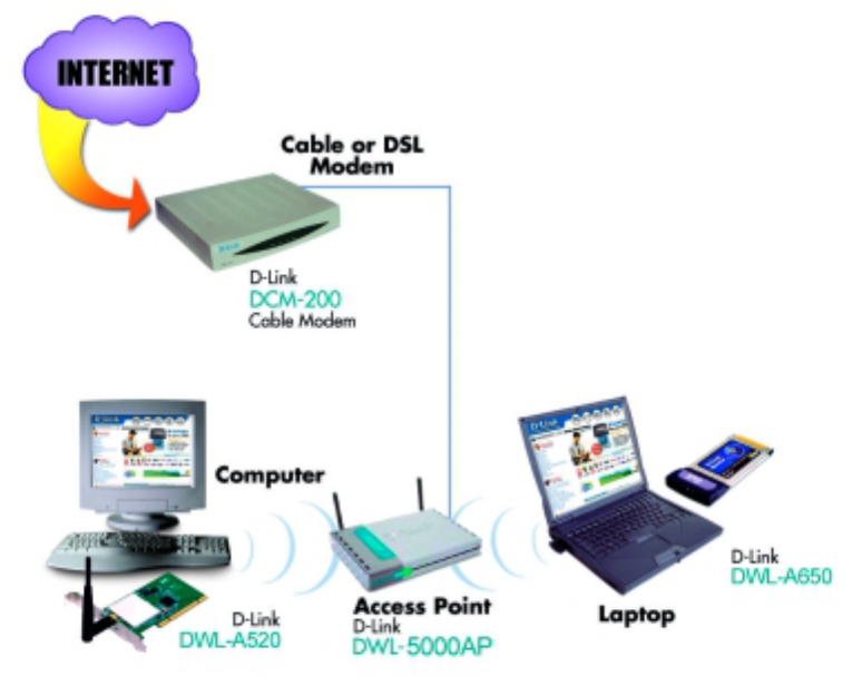
2. A Home Internet Network with Multiple IP Addresses
(Network administrators with Static IPs can also follow these instructions.)
If you have two or more computers (laptops or desktops) and want to share
files, printers, and Internet access using multiple IP addresses that you have
purchased from your Internet Service Provider -or- you want to connect to
an Ethernet network that uses Static IP Addresses, then follow the
instructions on the next page. When you have completed your network, it
should look similar to this:
Please note that this type of installation requires that your ISP (Internet
Service Provider) provides you a static IP address for each computer and
the Access Point on your network. Please refer to the manual that came
with your Access Point to determine its configuration.
2. A Home Internet Network with Multiple IP Addresses (continued)
Please follow these steps to complete the installation:
1. Connect the Wireless Access Point (the D-Link AirPro DWL-
5000AP) to a Broadband connection (i.e., a Cable modem such as
the D-Link DCM-200 cable modem.)
2. Install the D-Link AirPro DWL-A650 Wireless Cardbus Adapter
into the laptop computer(s) on your wireless network. (You can also
install the D-Link AirPro DWL-A520 Wireless PCI Adapter into your
desktop computers. Please refer to the Quick Install Guide
included with each product.)
3. Check the Device Manager to confirm that the wireless adapter is
installed correctly. Please refer to the Troubleshooting section in
this manual entitled: Checking the Installation of the Drivers for
the Wireless Adapter.
4. Set the Static IP Address of the wireless adapters. Please refer to
the Networking Basics section in this manual entitled: Assigning
an IP Address.
Note: The IP Address for all computers must be in the same IP Address
range, and the Subnet Mask must be the same for all the computers on the
network. For example: If the first computer is assigned an IP Address of
192.168.0.2 with a Subnet Mask of 255.255.255.0, then the second
computer should be assigned an IP Address of 192.168.0.3 with a Subnet
Mask of 255.255.255.0, etc. Each computer must have a unique IP Address.
If two devices share an identical AP Address, a conflict occurs, and one
device may not be visible on the network.
If you are using a PPPoE client (Point to Point Protocol over Ethernet)
please contact your ISP (Internet Service Provider) for further instructions
regarding connecting to the Internet.
5. Learn to share printers and files. Please refer to the Networking
Basics section in this manual entitled: Adding and Sharing Printers
in Windows XP.
16
Using the Configuration Utility
The Configuration Utility program for the DWL-5000AP is web-based. You
will need a JavaScript-enabled web-browser such as the Internet Explorer
4.0 or higher, or the Netscape Navigator 4.0 or higher. The computer that
you are using for initial configuration must have an IP Address within
the same range as the IP Address of the DWL-5000AP. (Please refer to
the Quick Installation Guide for more information.) If you are using a D-Link
router in your network, such as the DI-704P, with the factory default settings,
you will not need to assign a static IP Address. However, if you are not
using a D-Link router in your network, you will need to assign a Static IP
Address, within the IP Address Range of the DWL-5000AP. (Please see
Networking Basics in this manual for information on Assigning a Static IP
Address.)
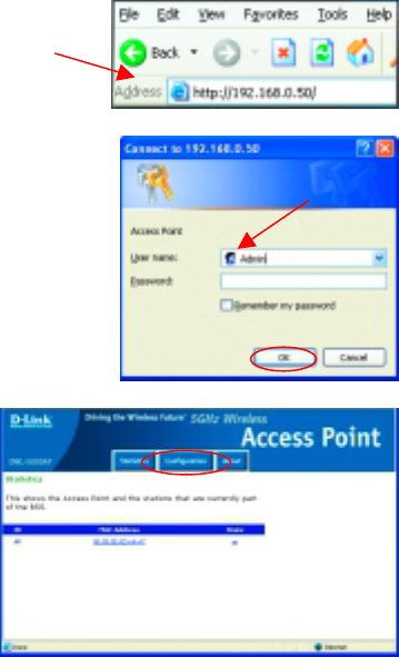
To use the Configuration Utility, open the web-browser and type in the IP
Address of the DWL-5000AP. The DWL-5000AP IP Address is shown below:
The screen below will appear.
•
••
• Open the web browser
•
••
• Type in the IP Address of
the Access Point
•
••
• Type Admin in the User
Name field (Upper case
A, lower case dmin)
•
••
• Leave the Password
blank
•
••
• Click OK
•
••
• Click
Configuration
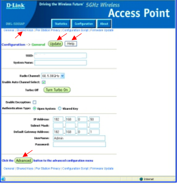
Using the Configuration Utility (continued)
General Configuration
In this window you can make changes to the default settings, if you wish.
D-Link 802.11a AirPro products network together, out of the box, with the
default settings. No configuration is needed. All computers on the network
must be within the same IP Address range, and have the same settings for
the Radio Channel, Turbo Mode and SSID in order to communicate.
•
••
• To make changes, enter the changes in the appropriate fields and
click Update.
•
••
• To create Advanced settings, click Advanced.
•
••
• If you need help, click Help in any Configuration window.
•
••
• To accept these Default Settings, make no changes in this window.
To view another Configuration window, click Shared Keys, near the
top of the window.
default
18
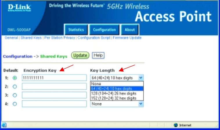
Using the Configuration Utility (continued)
Shared Keys
For added security on your network, you can use this window to configure
encryption keys. Encryption is optional. If you do use encryption, then all
the computers on the network, and the DWL-5000AP, must use the same
encryption key in order to communicate.
•
••
• From the pull-down Key Length menu, select the Key Length.
•
••
• Enter the Encryption Key. The Encryption Key must be in a
hexadecimal format. For 64-bit encryption, you must type exactly 10
hexadecimal digits in the Encryption key field; for 128-bit encryption,
you must type exactly 26 hexadecimal digits, and for 152-bit
encryption, you must type exactly 32 hexadecimal digits.
Note: Hexadecimal digits consist of the numbers 0-9 and the letters A-F.
•
••
• Click Update
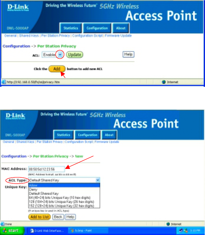
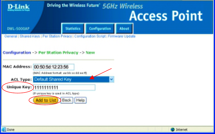
Using the Configuration Utility (continued)
Per Station Privacy
ACL (Access Control List) gives you the option of allowing or disallowing
association with the Access Point for certain computers on your network.
ACL is optional. MAC Addresses are used to create this list. If you choose
to use this function, please do the following:
•
••
• Click on the pull-down menu to the right of ACL, select Enable or
Disable
•
••
• Click Add to add a new ACL
•
••
• Input the MAC Address of the new member of the ACL
•
••
• ACL Type: For an extra level of security on the network, enter Default
Shared Key, or a specific Unique Key (either 64, 128 or 152 bits.) If
you select Allow in this field, you must keep the Unique Key field blank.
20
Using the Configuration Utility (continued)
Per Station Privacy
• If you select Default Shared Key in the ACL Type field, you will then
enter the WEP encryption key that is shared on your network into the
Unique Key field.
• If you select a specific Unique Key (such as 64, 128 or 152 bits) in the
ACL Type field, a Unique Key, in the format you selected (64,128,152
bits,) will be generated in the Unique Key field.
• Click Add to List
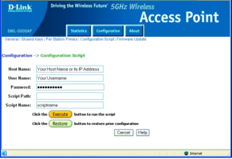
Using the Configuration Utility (continued)
Configuration Script
If you are using multiple Access Points on your network, after you have
completed the configuration of one DWL-5000AP, you can use the
Configuration Script to configure all the other DWL-5000APs. To use this
function, please do the following:
•
••
• Enter the Host Name of the computer in which the Script Name resides
•
••
• Enter the User Name and Password of the host computer
•
••
• Enter the Script Path using the format in the example above
•
••
• Enter the Script Name (the file name of the Configuration Script)
•
••
• Click Execute if you make any changes in this window
•
••
• Click Help for more information regarding writing Configuration Script
C:\foldername\filename
22
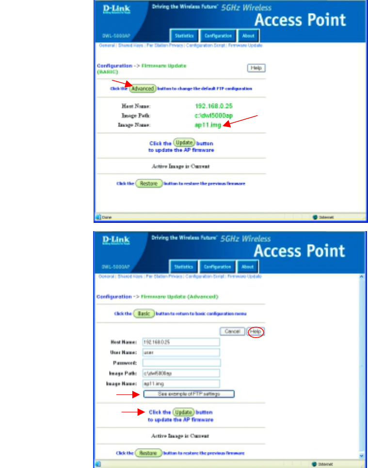
Using the Configuration Utility (continued)
Firmware Update
To update your firmware, an ftp server is required. Place the Image Name
file (ap11.img in the example below) in the root of the ftp server.
•
••
• Click
Advanced to
update the
firmware
(Note: Do not
power down
or cancel the
AP during the
update or the
update will be
lost.
Click Help at
any time for
more
information)
•
••
• Enter the IP
Address of the
ftp server in the
Host Name
field.
•
••
• Enter the User
Name.
(Anonymous
is frequently
used.)
•
••
• If there is no
password,
leave it blank.
•
••
• The Image
Path is not
required if the
image file is
placed in the
ftp root.
•
••
• Click Update
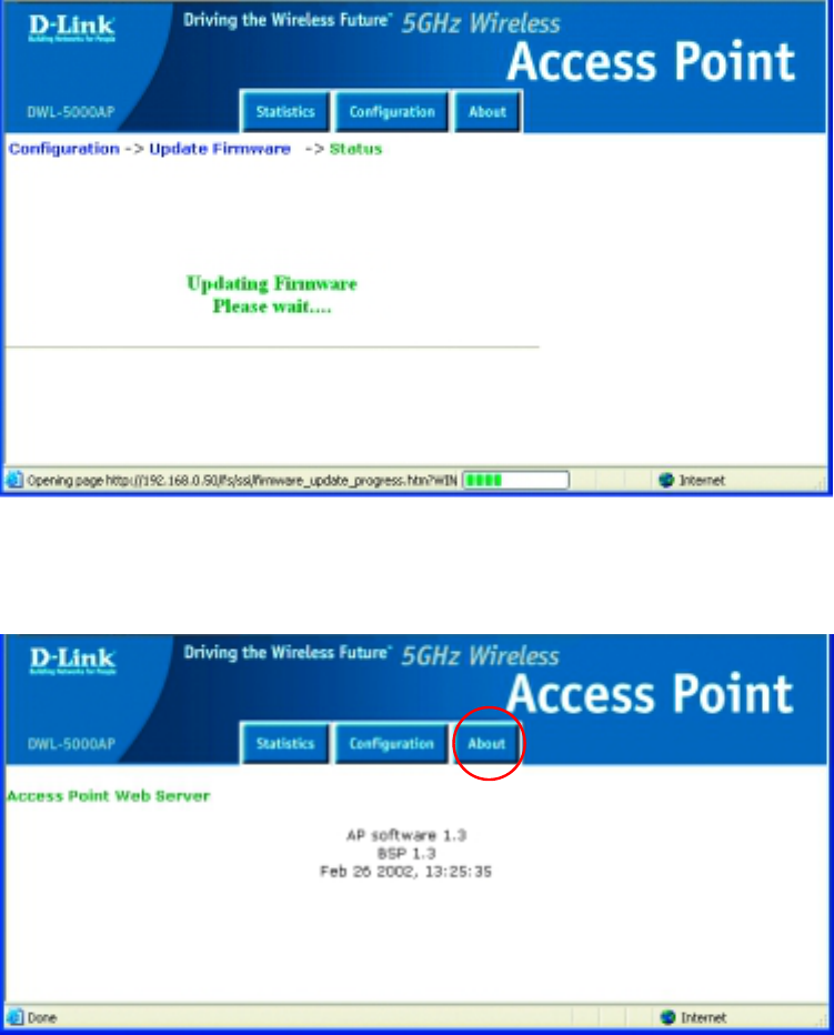
Using the Configuration Utility (continued)
Firmware Update
After you click Update, the screen below will appear. It may take a few
moments to update the Firmware.
•
••
• Click About, when the upgrade is complete. Information about the
updated firmware will be displayed.
24
Using the Configuration Utility (continued)
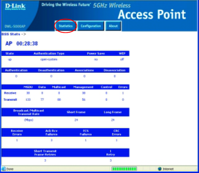
Statistics
•
••
• Click Statistics for more detailed information about the DWL-5000AP
It is recommended that you use an Ethernet connection for configuring the DWL-
5000AP through the web-browser.
Troubleshooting
This chapter provides solutions to problems that can occur during the
installation and operation of the DWL-5000AP Wireless Access Point. We
cover various aspects of the network setup, including the network adapters.
Please read the following if you are having problems.
(Note: It is recommended that you use an Ethernet connection to
configure the DWL-5000AP Access Point.)
1. The computer used to configure the DWL-5000AP cannot access the
Configuration menu.
• Check that the Ethernet LED on the DWL-5000AP is ON. If
the LED is not ON, check that the cable for the Ethernet
connection is securely inserted.
• Check that the Ethernet Adapter is working properly. Please
see item 6 (Check that the drivers for the network
adapters are installed properly) in this Troubleshooting
section to check that the drivers are loaded properly.
• Check that the IP Address is in the same range and subnet
as the DWL-5000AP. Please see Checking the IP Address
in Windows XP in the Networking Basics section of this
manual.
Note: The IP Address of the DWL-5000AP is 192.168.0.50. All the computers
on the network must have a unique IP Address in the same range, e.g.,
192.168.0.x. Any computers that have identical IP Addresses will not be
visible on the network. They must all have the same subnet mask, e.g.,
255.255.255.0
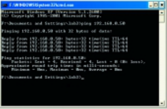
• Do a Ping test to make sure that the DWL-5000AP is
responding. Go to Start>Run>Type Command>Type ping
192.168.0.50. A successful ping will show four replies.
26
Troubleshooting (continued)
2. The computer with the wireless adapter installed is unable to
connect to the wireless network.
In the example below, we show you the settings of the DWL-A650 wireless
cardbus adapter. You may be using other adapters, but the procedure will
remain the same. The first screen and the path to reach it, can be found in
the Networking Basics section in this manual entitled: Checking the
Wireless Configuration of the Network Adapter. The second screen and
the path to reach it, can be found in the Using the Configuration Utility
section of this manual.
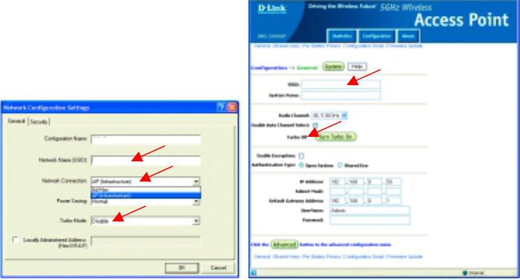
•
••
• In Infrastructure mode, make sure the same Service Set Identifier
(SSID) is specified in the settings for the wireless clients and access
points. The SSID factory default setting for the D-Link AirPro products
is default (lower-case d, with the remainder of the word in lower-case.)
Please refer to Checking the Wireless Configuration in the
Networking Basics section of this manual for more information.
•
••
• Check that the Network Connection for the wireless client is
configured properly. Select AP (Infrastructure) when connecting to
an access point. Double-click on the Local Area Connection icon in
the taskbar > click on Properties > click on Configure > select the
Settings Tab > click on Modify to change the settings for the wireless
adapter. (Please refer to Checking the Wireless Configuration in
the Networking Basics section of this manual for more information.)
DWL-5000AP Settings
802.11a Network Adapte
r
Settings
default
default
default
Troubleshooting (continued)
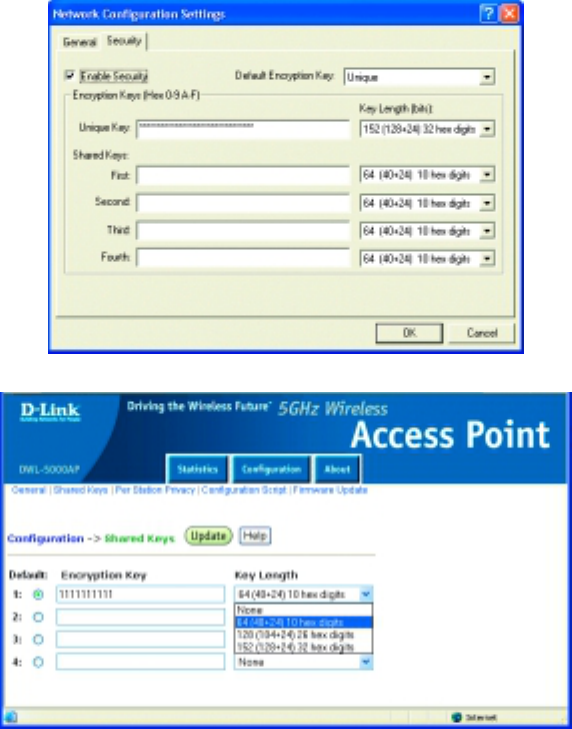
•
••
• Verify that the Turbo Mode setting is exactly the same for wireless
clients and the DWL-5000AP. Please note that the wireless
connection will not be established in Infrastructure or Ad-Hoc mode if
Turbo Mode is enabled on one end of the wireless connection and not
the other. (Please refer to Checking the Wireless Configuration in
the Networking Basics section of this manual for more information.)
•
••
• If Enable Security is selected, make sure that the correct encryption
keys are entered on both the wireless clients and the access points.
(Please see Checking the Wireless Configuration in the
Networking Basics section of this manual for more information.)
802.11a Network Adapter Encryption
DWL-5000AP Encryption
28
Troubleshooting (continued)
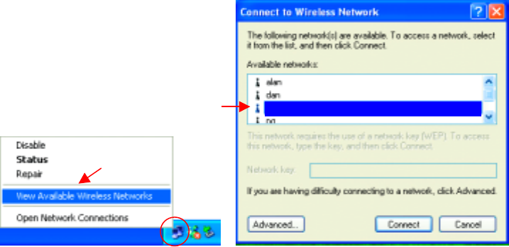
3. The wireless client cannot access the Internet in the Infrastructure
mode.
•
••
• Make sure the wireless client is associated and joined with the correct
Access Point. To check this connection: Right-click on the Local
Area Connection icon in the taskbar> select View Available
Wireless Networks. The Connect to Wireless Network screen will
appear. Please make sure you have selected the correct available
network, as shown in the illustrations below.
•
••
• Check that the IP Address assigned to the wireless adapter is within
the same IP Address range as the access point and gateway. Since
the DWL-5000AP has an IP Address of 192.168.0.50, wireless
adapters must have an IP Address in the same range, e.g.,
192.168.0.x. Each device must have a unique IP Address; no two
devices may have the same IP Address. The subnet mask must be
the same for all the computers on the network.) To check the IP
Address assigned to the wireless adapter, double-click on the
Local Area Connection icon in the taskbar > select the Support
tab and the IP Address will be displayed. (Please refer to Checking
the IP Address in the Networking Basics section of this manual.)
•
••
• If it is necessary to assign a Static IP Address to the wireless
adapter, please refer to the appropriate section in Networking
Basics. If you are entering a DNS Server address you must also
enter the Default Gateway Address. (Remember that if you have a
DHCP-capable router, you will not need to assign a Static IP Address.
See Networking Basics: Assigning a Static IP Address.)
default
Troubleshooting (continued)
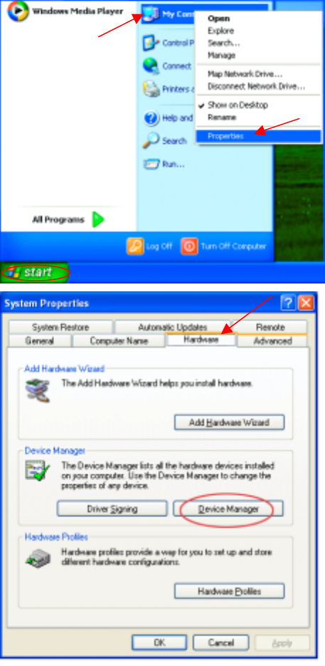
4. Check that the drivers for the network adapters are installed
properly.
You may be using different network adapters, but this procedure will remain the
same, regardless of the type of network adapters you are using.
•
••
• Go to Start
•
••
• Right-click on
My Computer
•
••
• Click Properties
•
••
• Select the
Hardware Tab
•
••
• Click Device
Manager
30
Troubleshooting (continued)
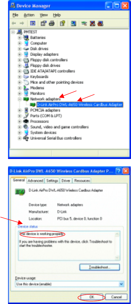
•
••
• Double-click on Network
Adapters
•
••
• Right-click on D-Link Air
Pro DWL-A650 Wireless
Cardbus Adapter
•
••
• Select Properties to check
that the drivers are
installed properly
• Look under Device
Status to check that the
device is working
properly.
•
Click
OK
Troubleshooting (continued)
5. Resetting the DWL-5000AP to Factory Default Settings
After you have tried other methods for troubleshooting your network, you
may choose to Reset the DWL-5000AP to the factory default settings.
Remember that all 802.11a D-Link AirPro products network together, out
of the box, at the factory default settings.
To hard-reset the D-Link AirPro DWL-5000AP to Factory Default Settings,
please do the following:
• Locate the Reset button on the back of the DWL-5000AP
• Use a paper clip to press the Reset button.
• Hold for about 5 seconds and then release
• After the DWL-5000AP reboots (this may take a few moments) it will
be reset to the factory Default settings.
32
Networking Basics
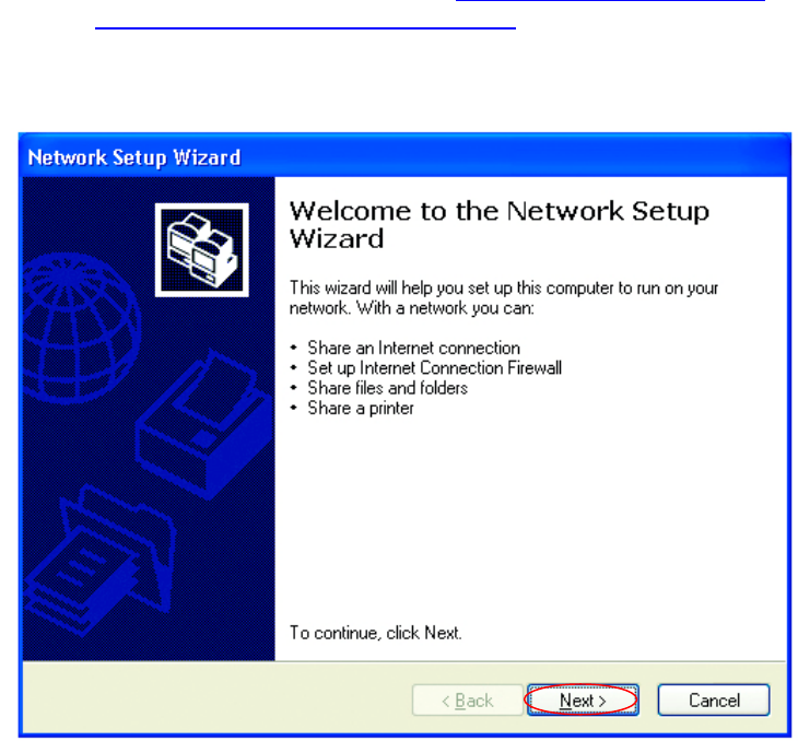
Using the Network Setup Wizard in Windows XP
In this section you will learn how to establish a network at home or work,
using Microsoft Windows XP.
Note: Please refer to websites such as http://www.homenethelp.com
and http://www.microsoft.com/windows2000 for information about
networking computers using Windows 2000, ME or 98.
Go to Start>Control Panel>Network Connections
Select Set up a home or small office network
When this screen appears, Click Next.
Networking Basics
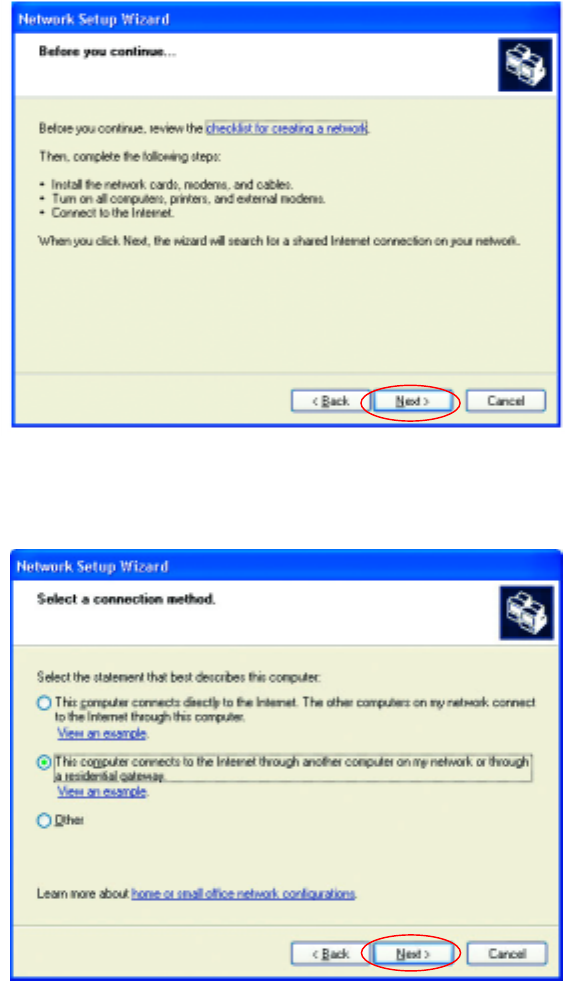
Please follow all the instructions in this window:
Click Next
In the following window, select the best description of your computer. If your
computer connects to the internet through a gateway/router, select the
second option as shown.
Click Next
34
Networking Basics
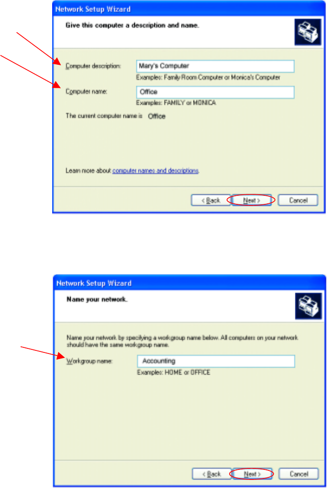
Enter a Computer description and a Computer name (optional.)
Click Next
Enter a Workgroup name. All computers on your network should have the
same Workgroup name.
Click Next
Networking Basics
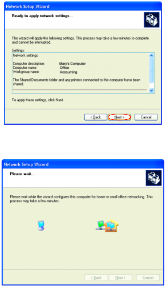
Please wait while the Network Setup Wizard applies the changes.
When the changes are complete, click Next.
Please wait while the Network Setup Wizard configures the computer.
This may take a few minutes.
36
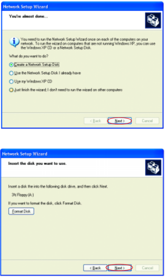
Networking Basics
In the window below, select the best option. In this example, Create a
Network Setup Disk has been selected. You will run this disk on each of
the computers on your network. Click Next.
Insert a disk into the Floppy Disk Drive, in this case drive A.
Format the disk if you wish, and click Next.
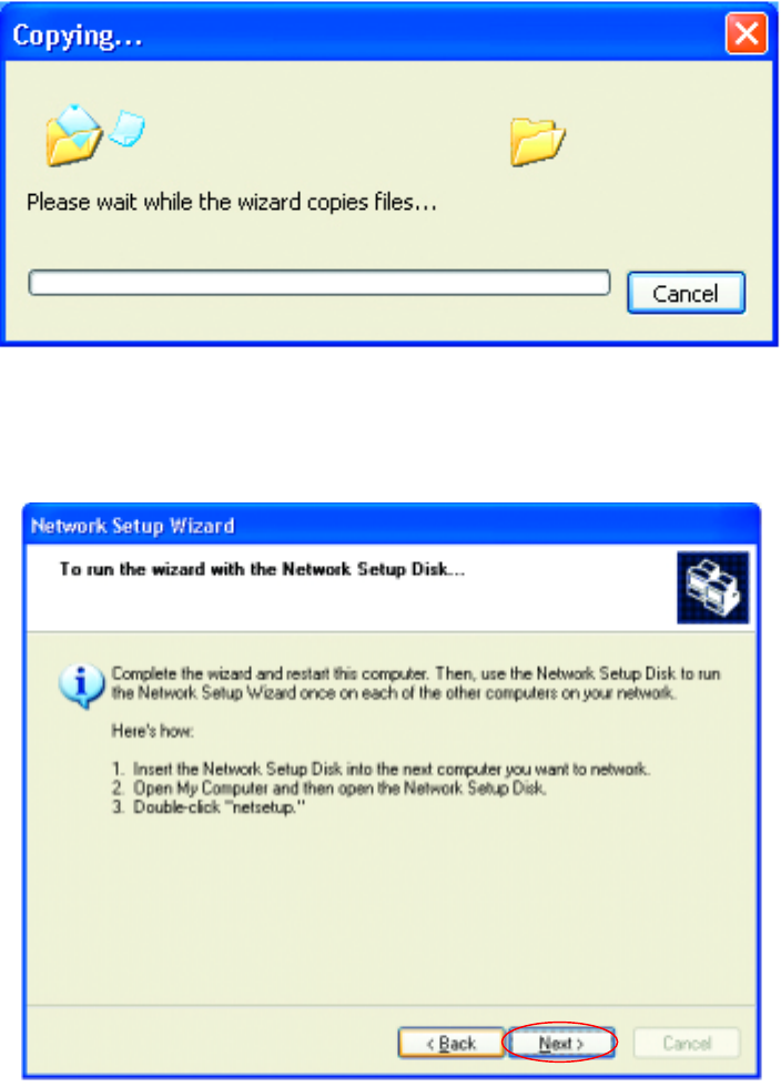
Networking Basics
Please wait while the Network Setup Wizard copies the files.
Please read the information under Here’s how in the screen below. After
you complete the Network Setup Wizard you will use the Network Setup
Disk to run the Network Setup Wizard once on each of the computers on
your network. To continue click Next.
38
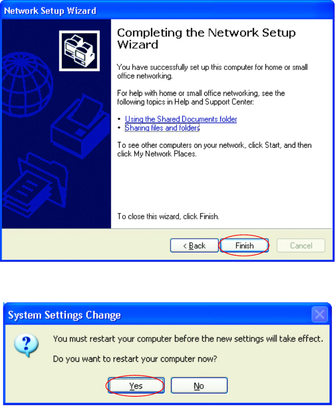
Networking Basics
Please read the information on this screen, then click Finish to complete the
Network Setup Wizard.
The new settings will take effect when you restart the computer. Click Yes
to restart the computer.
You have completed configuring this computer. Next, you will need to run
the Network Setup Disk on all the other computers on your network. After
running the Network Setup Disk on all your computers, your new wireless
network will be ready to use.
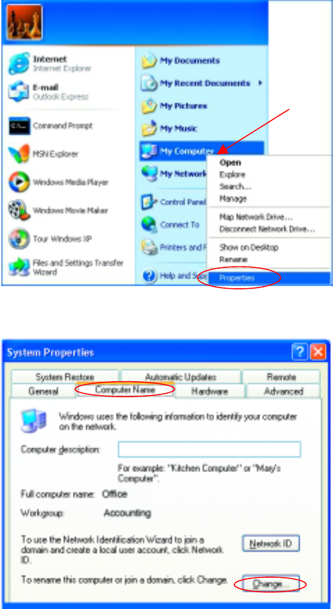
Networking Basics
Naming your Computer
To name your computer, please follow these directions:
In Windows XP:
• Click Start (in the
lower left corner of
the screen)
• Right-click on My
Computer
• Select Properties
and click
• Select the
Computer Name
Tab in the System
Properties window.
You may enter a
Computer description if
you wish, this field is
optional.
To rename the computer
and join a domain,
• Click Change
40
Networking Basics
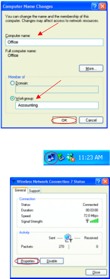
Naming your Computer (continued)
Checking the Wireless Configuration of the Network Adapter
• In this window, enter
the Computer
name.
• Select Workgroup
and enter the name
of the Workgroup.
• All computers on
your network must
have the same
Workgroup name.
• Click OK
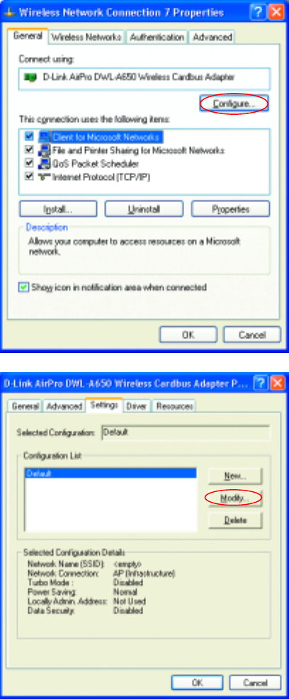
• Double-click on the Local Area
Connection Icon in the taskbar.
In this window you will see
the Signal Strength and the
Status of the network
adapter.
In this case the Status and
the Signal Strength are fine.
For more information:
• Click Properties
Networking Basics
Checking the Wireless Configuration of the Network Adapter
• Click Configure to
access more
information.
• Select Settings
This screen shows the
wireless configuration.
• Click Modify to
check on the
configuration.
42
Networking Basics
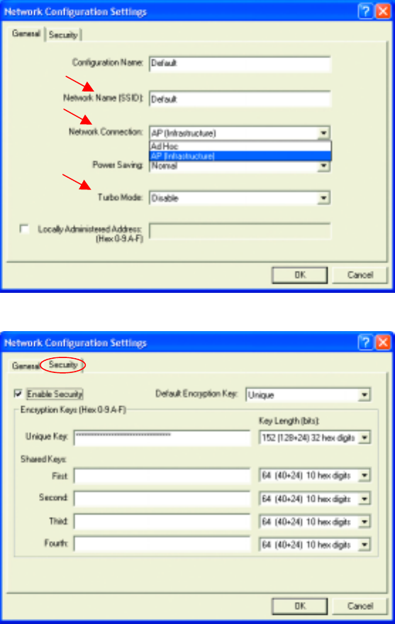
Checking the Wireless Configuration of the Network Adapter
• The Network
Name (SSID)
should be set to
Default.
• The Network
Connection
should be set to
the correct mode
(Infrastructure
or Ad Hoc.)
• The Turbo Mode
setting (Disabled
in the example
here) must be
the same on all
the stations in
your network.
• Click on the
Security Tab
• If Enable
Security is
selected on one
station on your
network, it must
be selected on
all stations.
Likewise, if
Enable Security
is deselected on
one station, it
must be
deselected on all
stations.
• Check to see that your IP Address and your Subnet Mask are in the correct
range. See the Networking Basics sections: Checking the IP Address and
Assigning a Static IP Address.
Networking Basics
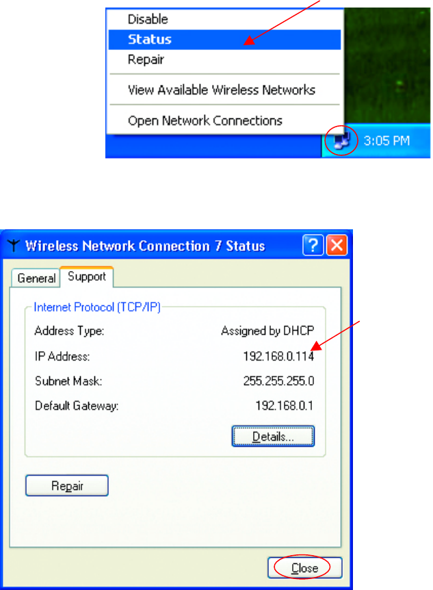
Checking the IP Address in Windows XP
The wireless adapter-equipped computers in your network must be in the
same IP Address range (see Getting Started in this manual for a definition
of IP Address Range.) To check on the IP Address of the adapter, please
do the following:
The following window will display
•
••
• Click the Support tab.
• Click Close
• Right-click on the
Local Area
Connection icon in
the task bar
• Click on Status
44
Networking Basics
Assigning a Static IP Address
Note: Residential Gateways/Broadband Routers will automatically assign IP
Addresses to the computers on the network, using DHCP (Dynamic Host
Configuration Protocol) technology. If you are using a DHCP-capable
Gateway/Router you will not need to assign Static IP Addresses.
If you are not using a DHCP capable Gateway/Router, or you need to assign a
Static IP Address, please follow these instructions:
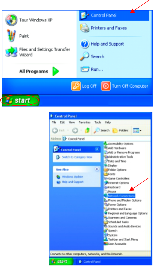
• Go to Start
• Double-click on
Control Panel
• Double-click on
Network Connections
Networking Basics
Assigning a Static IP Address
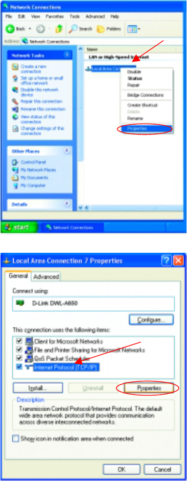
• Right-click on Local
Area Connections.
• Double-click
Properties
• Highlight Internet
Protocol (TCP/IP)
• Click Properties
46
Networking Basics
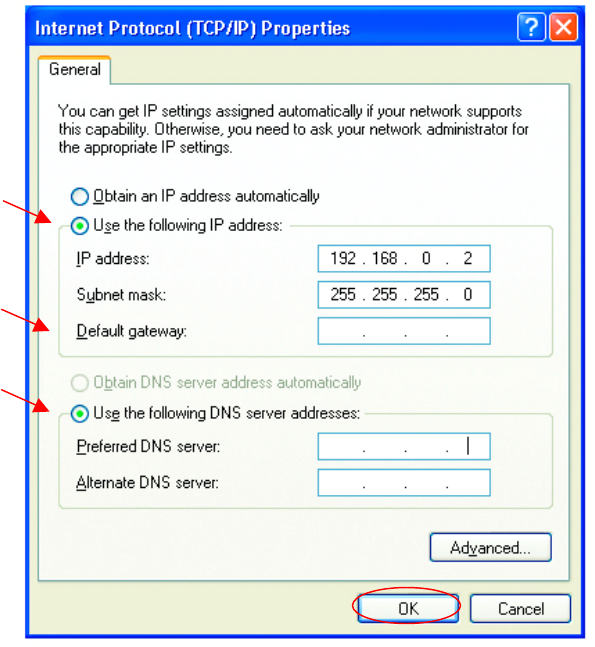
Assigning a Static IP Address
• Select Use the following IP address
in the Internet Protocol (TCP/IP) Properties window,
• Input your IP address and subnet mask. (The IP Addresses on your
network must be within the same range. For example, if one computer
has an IP Address of 192.168.0.2, the other computers should have IP
Addresses that are sequential, like 192.168.0.3 and 192.168.0.4. The
subnet mask must be the same for all the computers on the network.)
• Input your DNS server addresses. (Note: If you are entering a DNS
server, you must enter the IP Address of the Default Gateway.)
The DNS server information will be provided by your ISP (Internet Service
Provider.)
• Click OK
You have completed the assignment of a Static IP Address. (You do not need to
assign a Static IP Address if you have a DHCP-capable Gateway/Router.)
Networking Basics
Adding and Sharing Printers in Windows XP
After you have run the Network Setup Wizard on all the computers in your
network (please see the Network Setup Wizard section at the beginning of
Networking Basics,) you can use the Add Printer Wizard to add or share a
printer on your network.
Whether you want to add a local printer (a printer connected directly to one
computer,) share an LPR printer (a printer connected to a print server) or
share a network printer (a printer connected to your network through a
Gateway/Router,) use the Add Printer Wizard. Please follow the directions
below:
First, make sure that you have run the Network Setup Wizard on all of
the computers on your network.
We will show you 3 ways to use the Add Printer Wizard
1. Adding a local printer
2. Sharing an network printer
3. Sharing an LPR printer
Adding a local printer
(A printer connected directly to a computer)
A printer that is not shared on the network and is connected directly to one
computer is called a local printer. If you do not need to share your printer
on a network, follow these directions to add the printer to one computer.
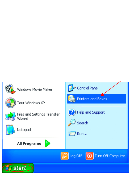
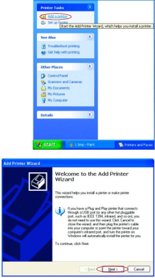
• Go to Start>
Printers and
Faxes
48
Networking Basics
Adding a local printer
• Click on Add a printer
• Click Next
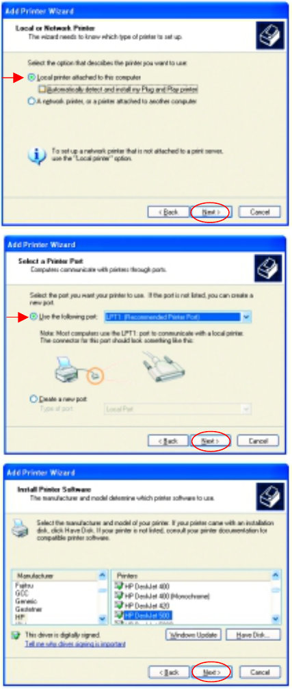
Networking Basics
Adding a local printer
• Select Local printer
attached to this computer
• (Deselect Automatically detect
and install my Plug and Play
printer if it has been selected.)
• Click Next
• Select Use the
following port:
• From the pull-down
menu select the
correct port for your
printer
(Most computers use the
LPT1: port, as shown in
the illustration.)
• Click Next
• Select and highlight the
correct driver for your
printer.
• Click Next
(If the correct driver is no
t
displayed, insert the CD o
r
floppy disk that came with you
r
p
rinter and click Have Disk.)
50
Networking Basics
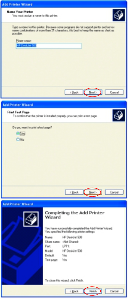
Adding a local printer
• At this screen, you can
change the name of the
printer (optional.)
• Click Next
• Select Yes, to print a
test page. A
successful printing will
confirm that you have
chosen the correct
driver.
• Click Next
This screen gives you
information about your
printer.
• Click Finish
Networking Basics
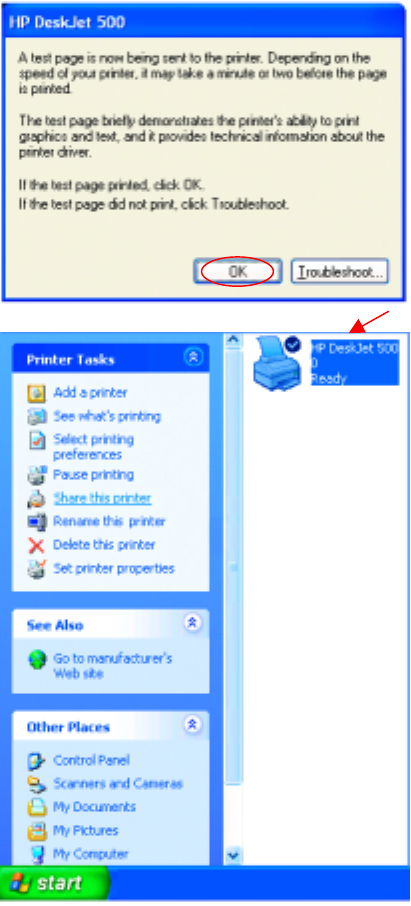
Adding a local printer
When the test page has
printed,
• Click OK
• Go to Start> Printers and
Faxes
A
successful installation wil
l
display the printer icon as
shown at right.
You have successfully added a
local printer.
52
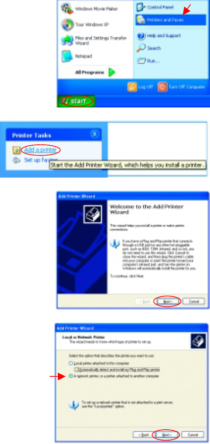
Networking Basics
Sharing a network printer
After you have run the Network Setup Wizard on all the computers on your
network, you can run the Add Printer Wizard on all the computers on your
network. Please follow these directions to use the Add Printer Wizard to
share a printer on your network:
• Go to Start>
Printers and Faxes
• Click on Add a Printer
• Click Next
• Select Network Printer
• Click Next
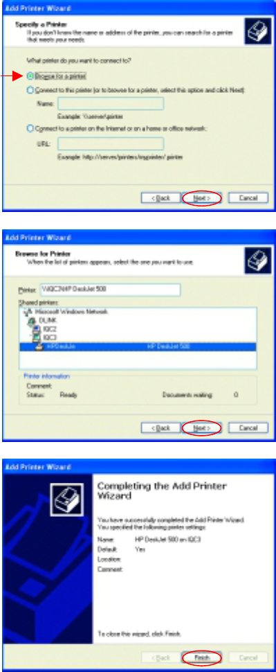
Networking Basics
Sharing a network printer
• Select Browse for a printer
• Click Next
• Select the printer you
would like to share.
• Click Next
• Click Finish
54
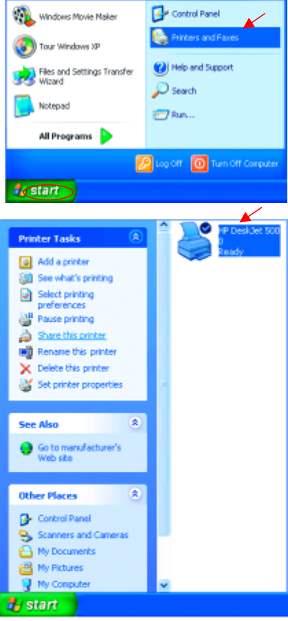
Networking Basics
Sharing a network printer
To check for proper installation:
• Go to Start>
Printers and Faxes
The printer icon will appear
at right, indicating proper
installation.
You have completed
adding the printer.
To share this printer on
your network:
• Remember the
printer name
• Run the Add Printer
Wizard on all the
computers on your
network.
• Make sure you have
already run the
Network Setup
Wizard on all the
network computers.
A
fter you run the Add
Printer Wizard on all the
computers in the
network, you can share
the printer.
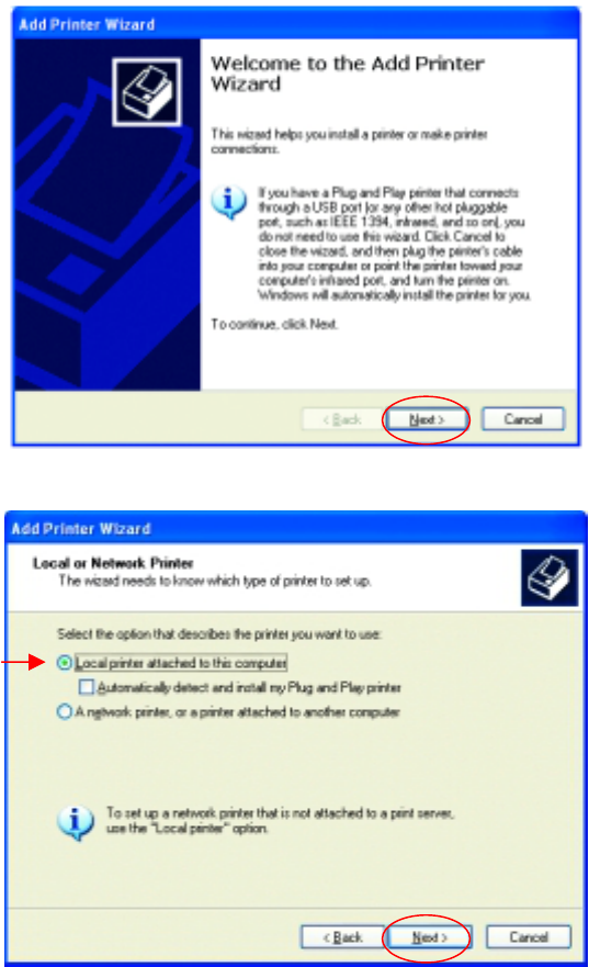
Networking Basics
Sharing an LPR printer
To share an LPR printer (using a print server,) you will need a Print Server such as
the DP-101P+. Please make sure that you have run the Network Setup Wizard on
all the computers on your network. To share an LPR printer, please follow these
directions:
• Go to Start>
Printers
and Faxes
• Click on
Add a Printer
The screen to the
right will display.
• Click Next
• Select
Local printer…
• Click Next
56
Networking Basics
Sharing an LPR printer
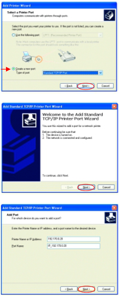
• Select Create a new port
• From the pull-down menu,
select Standard TCP/IP
Port, as shown.
• Click Next
• Please read the instructions
on this screen.
• Click Next
• Enter the Printer IP
Address and the Port
Name, as shown.
• Click Next
Networking Basics
Sharing an LPR printer
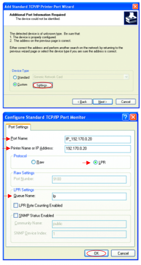
• In this screen,
select Custom.
• Click Settings
• Enter the Port
Name and the
Printer Name or
IP Address.
• Select LPR
• Enter a Queue
Name (if your
Print-Server/
Gateway has
more than one
port, you will
need a Queue
name.)
• Click OK
58
Networking Basics
Sharing an LPR printer
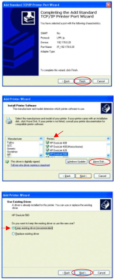
• This screen will show
you information
about your printer.
• Click Finish
• Select the printer you
are adding from the
list of Printers.
• Insert the printer
driver disk that came
with your printer.
• Click Have Disk
If the printer driver is already
installed,
• Select Keep existing
driver
• Click Next
Networking Basics
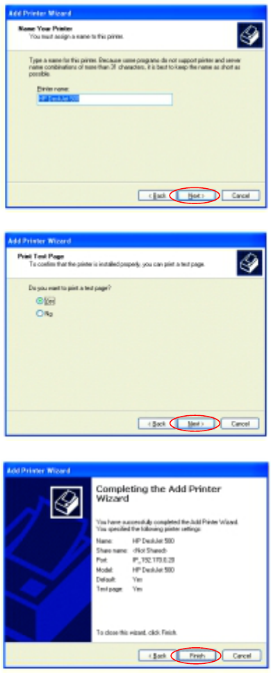
Sharing an LPR printer
• You can rename your
printer if you choose. It
is optional.
Please remember the name o
f
your printer. You will need this
information when you use the
Add Printer Wizard on the
other computers on you
r
network.
• Click Next
• Select Yes, to print a
test page.
• Click Next
This screen will display
information about your
printer.
• Click Finish to
complete the
addition of the
printer.
• Please run the
Add Printer
Wizard on all the
computers on your
network in order to
share the printer.
Note: You must run the Network Setup Wizard
on all the computers on your network before you
run the Add Printer Wizard.
60
Networking Basics
Other Tasks
For help with other tasks in home or small office networking, see Using the
Shared Documents folder and Sharing files and folders in the Help and
Support Center in Microsoft Windows XP.
Technical Specifications
Standards
• IEEE 802.11a (Wi-Fi5)
• IEEE 802.3 and IEEE 802.3u
• IEEE 802.1d
Ports • (1) 10/100Base-T Ethernet, RJ-45 (UTP)
• (1) Power – 3.3V DC, 2.6A
Network Management
• Web-Based browser with JavaScript
Frequency Range
• 5.150-5.85 GHz
Data Rates
• 6, 9, 12, 18, 24, 36, 48, 54, 72, 96,128 Mbps
Modulation Technology
• Orthogonal Division Frequency Multiplexing (OFDM)
Modulation Techniques
• BPSK (Binary Phase Shift Keying)
• QPSK (Quadrature Phase Shift Keying)
• 16 QAM (Quadrature Amplitude Modulation)
• 64 QAM (Quadrature Amplitude Modulation)
Data Security
• 64, 128, 154-bit WEP (Wired Equivalent Privacy) Encryption
• Access Control LIst
Media Access Control
• CSMA/CA
Diagnostic LED
• Power
• Ethernet Link/Activity LAN1
• Fast Ethernet Link/Activity LAN1
• Ethernet Link/Activity LAN2
• Fast Ethernet Link/Activity LAN2
• Wireless Activity
Operating Voltage
• 5V± -10%
Network Architecture
• Supports Infrastructure Mode (Communications to wired
networks via Access Points with Roaming)
Antenna Type
• Dual 5dBi dipole antennas with diversity
• Power parameter software configurable
Available Channels:
• Thirteen non-overlapping channels for North America
MTBF (Mean Time Between Failure)
• >30,000 hours
Physical Dimensions
• L ~ 9.25 inches (235mm)
• W ~ 6.38 inches (162 mm)
• H ~ 1.63 inches (41mm)
Temperature
• Operating: 0ºC to 55ºC (32ºF to 131ºF)
• Storing: -20ºC to 65ºC (-4ºF to 149ºF)
Humidity:
• 5%-95%, non-condensing
Emissions:
• FCC part 15b
• UL1950-3
• Canada CSA 950/ America UL 1950/ Nation
• IEC 950
• Europe EN 60950
Warranty
• Three Years
62
Contacting Technical Support
You can find the most recent software and user documentation on the D-Link
website.
D-Link provides free technical support for customers within the United States
for the duration of the warranty period on this product.
U.S. customers can contact D-Link technical support through our web site,
or by phone.
D-Link Technical Support over the Telephone:
(800) 758-5489
24 hours a day, seven days a week.
D-Link Technical Support over the Internet:
http://support.dlink.com
When contacting technical support, please provide the following information:
• Serial number of the unit
• Model number or product name
• Software type and version number

Limited Warranty and Registration
D-Link Systems, Inc. (“D-Link”) provides this 3-Year warranty for its product only to the person or entity
who originally purchased the product from:
• D-Link or its authorized reseller or distributor.
• Products purchased and delivered with the fifty United States, the District of Columbia, US
Possessions or Protectorates, US Military Installations, addresses with an APO or FPO.
3-Year Limited Hardware Warranty: D-Link warrants that the hardware portion of the D-Link products
described below (“Hardware”) will be free from material defects in workmanship and materials from the
date of original retail purchase of the Hardware, for the period set forth below applicable to the product
type (“Warranty Period”).
3-Year Limited Warranty for the Product(s) is defined as follows
• Hardware (excluding power supplies and fans)
• Spare parts and spare kits Ninety (90) days.
D-Link’s sole obligation shall be to repair or replace the defective Hardware at no charge to the original
owner. Such repair or replacement will be rendered by D-Link at an Authorized D-Link Service Office. The
replacement Hardware need not be new or of an identical make, model or part; D-Link may in its
discretion replace the defective Hardware (or any part thereof) with any reconditioned product that D-Link
reasonably determines is substantially equivalent (or superior) in all material respects to the defective
Hardware. The Warranty Period shall extend for an additional ninety (90) days after any repaired or
replaced Hardware is delivered. If a material defect is incapable of correction, or if D-Link determines in
its sole discretion that it is not practical to repair or replace the defective Hardware, the price paid by the
original purchaser for the defective Hardware will be refunded by D-Link upon return to D-Link of the
defective Hardware. All Hardware (or part thereof) that is replaced by D-Link, or for which the purchase
price is refunded, shall become the property of D-Link upon replacement or refund.
Limited Software Warranty: D-Link warrants that the software portion of the product (“Software”) will
substantially conform to D-Link’s then current functional specifications for the Software, as set forth in the
applicable documentation, from the date of original delivery of the Software for a period of ninety (90)
days (“Warranty Period”), if the Software is properly installed on approved hardware and operated as
contemplated in its documentation. D-Link further warrants that, during the Warranty Period, the magnetic
media on which D-Link delivers the Software will be free of physical defects. D-Link’s sole obligation shall
be to replace the non-conforming Software (or defective media) with software that substantially conforms
to D-Link’s functional specifications for the Software. Except as otherwise agreed by D-Link in writing, the
replacement Software is provided only to the original licensee, and is subject to the terms and conditions
of the license granted by D-Link for the Software. The Warranty Period shall extend for an additional
ninety (90) days after any replacement Software is delivered. If a material non-conformance is incapable
of correction, or if D-Link determines in its sole discretion that it is not practical to replace the non-
conforming Software, the price paid by the original licensee for the non-conforming Software will be
refunded by D-Link; provided that the non-conforming Software (and all copies thereof) is first returned to
D-Link. The license granted respecting any Software for which a refund is given automatically terminates.
What You Must Do For Warranty Service:
Registration is conducted via a link on our Web Site (http://www.dlink.com/). Each product purchased
must be individually registered for warranty service within ninety (90) days after it is purchased and/or
licensed.
FAILURE TO PROPERLY TO REGISTER MAY AFFECT THE WARRANTY FOR THIS PRODUCT.
Submitting A Claim. Any claim under this limited warranty must be submitted in writing before the end of
the Warranty Period to an Authorized D-Link Service Office.
• The customer must submit as part of the claim a written description of the Hardware defect or
Software nonconformance in sufficient detail to allow D-Link to confirm the same.
• The original product owner must obtain a Return Material Authorization (RMA) number from the
Authorized D-Link Service Office and, if requested, provide written proof of purchase of the product
(such as a copy of the dated purchase invoice for the product) before the warranty service is provided.
• After an RMA number is issued, the defective product must be packaged securely in the
original or other suitable shipping package to ensure that it will not be damaged in transit, and the
RMA number must be prominently marked on the outside of the package.
• The customer is responsible for all shipping charges to and from D-Link (No CODs allowed).
Products sent COD will become the property of D-Link Systems, Inc. Products should be fully insured
by the customer and shipped to D-Link Systems Inc., 53 Discovery Drive, Irvine CA 92618.
D-Link may reject or return any product that is not packaged and shipped in strict compliance with the
foregoing requirements, or for which an RMA number is not visible from the outside of the package. The
product owner agrees to pay D-Link’s reasonable handling and return shipping charges for any product
64
that is not packaged and shipped in accordance with the foregoing requirements, or that is determined by
D-Link not to be defective or non-conforming.
What Is Not Covered:
This limited warranty provided by D-Link does not cover: Products that have been subjected to abuse,
accident, alteration, modification, tampering, negligence, misuse, faulty installation, lack of reasonable
care, repair or service in any way that is not contemplated in the documentation for the product, or if the
model or serial number has been altered, tampered with, defaced or removed; Initial installation,
installation and removal of the product for repair, and shipping costs; Operational adjustments covered in
the operating manual for the product, and normal maintenance; Damage that occurs in shipment, due to
act of God, failures due to power surge, and cosmetic damage; and Any hardware, software, firmware or
other products or services provided by anyone other than D-Link.
Disclaimer of Other Warranties: EXCEPT FOR THE 3-YEAR LIMITED WARRANTY SPECIFIED HEREIN, THE PRODUCT IS
PROVIDED “AS-IS” WITHOUT ANY WARRANTY OF ANY KIND INCLUDING, WITHOUT LIMITATION, ANY WARRANTY OF
MERCHANTABILITY, FITNESS FOR A PARTICULAR PURPOSE AND NON-INFRINGEMENT. IF ANY IMPLIED WARRANTY CANNOT BE
DISCLAIMED IN ANY TERRITORY WHERE A PRODUCT IS SOLD, THE DURATION OF SUCH IMPLIED WARRANTY SHALL BE
LIMITED TO NINETY (90) DAYS. EXCEPT AS EXPRESSLY COVERED UNDER THE LIMITED WARRANTY PROVIDED HEREIN, THE
ENTIRE RISK AS TO THE QUALITY, SELECTION AND PERFORMANCE OF THE PRODUCT IS WITH THE PURCHASER OF THE
PRODUCT.
Limitation of Liability: TO THE MAXIMUM EXTENT PERMITTED BY LAW, D-LINK IS NOT LIABLE UNDER ANY CONTRACT,
NEGLIGENCE, STRICT LIABILITY OR OTHER LEGAL OR EQUITABLE THEORY FOR ANY LOSS OF USE OF THE PRODUCT,
INCONVENIENCE OR DAMAGES OF ANY CHARACTER, WHETHER DIRECT, SPECIAL, INCIDENTAL OR CONSEQUENTIAL
(INCLUDING, BUT NOT LIMITED TO, DAMAGES FOR LOSS OF GOODWILL, WORK STOPPAGE, COMPUTER FAILURE OR
MALFUNCTION, LOSS OF INFORMATION OR DATA CONTAINED IN, STORED ON, OR INTEGRATED WITH ANY PRODUCT
RETURNED TO D-LINK FOR WARRANTY SERVICE) RESULTING FROM THE USE OF THE PRODUCT, RELATING TO WARRANTY
SERVICE, OR ARISING OUT OF ANY BREACH OF THIS LIMITED WARRANTY, EVEN IF D-LINK HAS BEEN ADVISED OF THE
POSSIBILITY OF SUCH DAMAGES. THE SOLE REMEDY FOR A BREACH OF THE FOREGOING LIMITED WARRANTY IS REPAIR,
REPLACEMENT OR REFUND OF THE DEFECTIVE OR NON-CONFORMING PRODUCT.
GOVERNING LAW: This 3-Year Warranty shall be governed by the laws of the state of California. Some
states do not allow exclusion or limitation of incidental or consequential damages, or limitations on how
long an implied warranty lasts, so the foregoing limitations and exclusions may not apply. This limited
warranty provides specific legal rights and the product owner may also have other rights which vary from
state to state.
Trademarks
Copyright® 2002 D-Link Corporation. Contents subject to change without prior notice. D-Link is a
registered trademark of D-Link Corporation/D-Link Systems, Inc. All other trademarks belong to their
respective proprietors.
Copyright Statement
No part of this publication may be reproduced in any form or by any means or used to make any
derivative such as translation, transformation, or adaptation without permission from D-Link
Corporation/D-Link Systems Inc., as stipulated by the United States Copyright Act of 1976.
FCC Statement
This equipment has been tested and found to comply with the limits for a Class B digital device, pursuant
to part 15 of the FCC Rules. These limits are designed to provide reasonable protection against harmful
interference in a residential installation. This equipment generates, uses and can radiate radio frequency
energy and, if not installed and used in accordance with the instructions, may cause harmful interference
to radio communication. However, there is no guarantee that interference will not occur in a particular
installation. If this equipment does cause harmful interference to radio or television reception, which can
be determined by turning the equipment off and on, the user is encouraged to try to correct the
interference by one or more of the following measures:
• Reorient or relocate the receiving antenna.
• Increase the separation between the equipment and receiver.
• Connect the equipment into an outlet on a circuit different from that to which the receiver is
connected.
• Consult the dealer or an experienced radio/TV technician for help.
Modifications to this device are not authorized, may violate FCC regulation Part 15.407, and will void the
warranty for this product. This device is intended to operate in the frequency band of 5.15 to 5.25 GHz
under all conditions of normal operation. According to FCC 15.407 (e), normal operation of this device is
restricted to indoor use only to reduce any potential harmful interference to co-channel Mobile Satellite
Systems, or radar systems that use 5.25 to 5.35 GHz and 5.65 to 5.85 GHz frequency bands. This
interference could also damage this device.
Registration: Register your D-Link AirPro DWL-5000AP online at http://www.dlink.com/sales/reg