D Link 2002020015-1 Wireless LAN Card User Manual Revised 041502
D Link Corporation Wireless LAN Card Users Manual Revised 041502
D Link >
Users Manual Revised 041502
WLAN PC CARD (AR)
.........................................................................................
User Guide
Table of Contents
Section 1
Introduction ........................................................................................... 1-1
1.1 Package Contents.....................................................................................1-1
1.2 System Requirements...............................................................................1-1
1.3 AT76C502A Features ...............................................................................1-1
1.4 Firmware Features....................................................................................1-2
1.5 Driver Features .........................................................................................1-2
Section 2
Installation Overview............................................................................. 2-1
Section 3
Installation and Configuration Procedures Under Windows
98/Me/2000........................................................................................... 3-1
3.1 What You Need to Know About Windows 98/Me/2000.............................3-1
3.2 What You Will Need..................................................................................3-1
3.3 Installing the Application and Drivers Under Windows 98/Me/2000 .........3-1
3.4 Uninstall Procedure Under Windows 98/Me .............................................3-6
3.5 Uninstall Procedure Under Windows 2000 ...............................................3-7
Section 4
Configuration & Monitor Utility .............................................................. 4-1
4.1 How to Install the Configuration & Monitor Utility......................................4-1
4.2 Using the Configuration & Monitor Utility ..................................................4-1
4.3 How to Uninstall the Configuration & Monitor Utility .................................4-7
Section 5
Firmware Upgrade Utility ...................................................................... 5-1
5.1 Firmware Upgrade Utility ..........................................................................5-1
Section 1
Introduction
The ATMEL PCMCIA Fast-VNET-R (5V) based on ATMEL AT76C502A Wireless Media Access
Controller is a network card with a rate of 1, 2, 5.5, and 11 Mbps operating in the ISM
band using Direct Sequence Spread Spectrum (DSSS) transmission implementing the
IEEE 802.11b standard. For this card ATMEL currently provides Device Drivers for MS
Windows® 98/2000, and Windows® Me. ATMEL also provides tools for the configuration
and firmware upgrade of the cards. These tools, as well as the installation procedure for
the MS Windows 98/2000, and Windows Me operating systems are described in this
document.
To install the adapter and operate under an operating system two pieces of software are
needed. The first one is the driver, which provides the necessary mechanisms to the
operating system in order to use the adapter as any other networking adapter. The
driver communicates with the firmware using exchange of commands (Set MIB, Get
MIB, Scan, Sync, etc.). The other piece of software needed is the code written on the
MAC chip, which is responsible for the interface with the driver, and for the implementation
of the IEEE 802.11b functions.
1.1 Package
Contents
Please make sure that your received the following with your AT76C502A-Evaluation Kit:
• One (1) PCMCIA Fast-VNET-R (5V) card
• User Guide
• Firmware, Drivers, and Software Tools CD
1.2 System
Requirements
• Operating System: MS Windows 98/2000, Windows Me with Service Pack 4 or later
• Desktop PC or notebook PC with CD-ROM drive
1.3 AT76C502A
Features
AT76C502A based Fast-VNET adapters offer compliance with the IEEE 802.11b specification.
This feature allows them to communicate with wireless devices from other
manufacturers that support the standard. Among the features of the AT76C502A WLAN
MAC controller are the following:
– Wireless interface following the IEEE 802.11b standard supporting DSSS 2.4 GHz
wireless PHY
– Wireless LAN MAC Unit with ARM7TDMI RISC processor
– Integrated 128-byte transmit and 128-byte receive FIFOs, for wireless MAC layer
functions
– 16-bit PCMCIA bus interface
– Glueless SRAM interface for all MAC operations, supporting up to 16 MB of external
memory
– Integrated 6Kx32 bit internal SRAM, used for fast program code execution and
temporary storage of data
– Glueless Flash memory interface, supporting up to 16 MB on non volatile memory
for permanent storage of program code
– Enciphering/deciphering of wireless data by the implementation of the WEP
algorithm
– Supports 11, 5.5, 2, and 1 Mbps rates
1.4 Firmware
Features
The IEEE 802.11b firmware implementation for the AT76C502A-EK supports:
– Distributed Coordination Function
CSMA/CA
Backoff Procedure
NAV Management
ACK Procedure
Retransmission of unacknowledged frames
– RTS/CTS Handshake
– Duplicate Detection and Recovery
– Beacon Generation (ad-hoc mode)
– Probe Response (ad-hoc mode)
– Fragmentation and Reassembly
– Wired Equivalent Privacy Algorithm (WEP-40 bits, 128 bits)
– Auto Rate Fallback
– TSF synchronization
– Short Preamble
1.5 Driver Features The drivers for the AT76C502-EK support:
– Roaming
– Preferred AP
– Dynamic configuration
– Site Survey
– Preamble Type detection
– Firmware Upgrade
– Authentication Algorithm (Open System, Shared Key)
Section 2
Installation Overview
This is a quick step by step guide on how to install your PCMCIA Fast-VNET-R (5V) card.
Please follow the steps described below and refer to the appropriate sections for further
details:
• Power on the computer (laptop).
• Please make sure that you don’t insert your PCMCIA CARD yet.
• Install the drivers and application:
Insert the given Installation CD into your CD-Rom drive. Select the Utilities & Drivers
folder.
Locate the executable file “setup.exe” and double click it.
Follow the installation instructions from the installSheild Wizard by pressing the
“Next” button.
Choose the type of installation you are going to perform (Application Only, Application
& PCMCIA Drivers, Application & USB Drivers or Application & PCMCIA & USB
Drivers).
Give the destination path of where the application will be installed. To set the path
of your choice select Browse and then Next.
Choose the Mode of Operation (Ad-Hoc or Infrastucture):
In Ad-Hoc Mode, set the ESSID of all station participating to be the same and
choose the channel of operation.
In Insfrastucture Mode, set the ESSID to be the same with the ESSID of the AP to
which you will be associated with.
Confirm the current settings of ESSID, Network Mode and Utility directory and click
Next.
Finish the installation.
• Plug your PCMCIA card.
• The “Add New Hardware Wizard” automatically loads the Drivers.
• Refer to sections 3 for more details on the installation and configuration under
Windows 98/2000 and Windows Me. Section 4 gives detailed instructions on how to
use the Configuration Utility while section 5 given detailed instructions on how to use
the Firmware Upgrade Utility.
Upgrading your Wireless LAN Software when a new setup is released:
For Windows 98/Me
• Power on the computer (laptop).
• Uninstall the application by running the uninstall program.
• When prompted for reboot select “YES”.
• After rebooting run the new setup.exe.
• When the setup of the application (see instructions above) is completed, you can then
plug your PCMCIA card.
Note: If you select the ”Application Only ” Installation option the installation procedure
will only install the Utility while selecting any other option it will also install the
latest drivers for your wireless card without prompting you.
For Windows 2000
• Power on the computer (laptop).
• Uninstall the application by running the uninstall program.
• When prompted for reboot select “YES”.
• Run the new setup.exe.
• When the setup of the drivers and application (see instructions above) is completed,
you can then plug your PCMCIA card.
Section 3
Installation and Configuration
Procedures Under Windows
98/Me/2000
Use the procedures described in this chapter to install and configure the Fast-VNET
PCMCIA card under MS Windows 98/Me/2000.
3.1 What You Need
to Know About
Windows
98/Me/2000
Although similar in appearance, Windows 98/Me/2000 have different philosophies when
installing a new hardware.
Throughout this section it is assumed that you have a basic working knowledge of Windows
98/Me/2000 and of how to install new network cards on them. However, in this
paragraph, some specific features of Windows 98/Me/2000 are briefly explained.
Windows 98/Me/2000 operating system supports the “Plug & Play” feature. That means
that once you plug the Fast-VNET card for the very first time, the operating system will
detect the card and automatically install the driver assuming that you have already
installed the application utility.
Another feature is the “Hot Swapping”. With this feature, you can unplug and plug again
the card whenever you want.
3.2 What You Will
Need
During the installation, you may be prompted to load operating system files from the
Windows installation disk. Please have this disk handy.
You will need the Firmware and Software Tools CD provided with your Evaluation Kit.
Note: In order to be able to install the Fast-VNET card on to your PC running under
Windows 2000, you will need to log on as “Administrator”.
3.3 Installing the
Application and
Drivers Under
Windows
98/Me/2000
Note: Please do not plug your PCMCIA card until the Application setup has been
completed. The setup procedure described below installs the drivers, the
Configuration & Monitor Utility and the Firmware Upgrade Utility.
1. Insert the Firmware and Software Tools CD into your CD-ROM drive and locate
the executable file “setup.exe”.
2. Follow the installation instructions from the InstallShield Wizard by pressing the
“Next” button.
3. During the setup process, the window of Figure 3-1 will appear prompting you to
select the adapter type you are going to install. If you plan to install an ATMEL
PCMCIA (A) card only, then you must choose the “Application & PCMCIA Drivers” option.
However, if you plan to install an ATMEL USB (A) card in the futureI, select the
“Application, PCMCIA & USB Drivers” option.
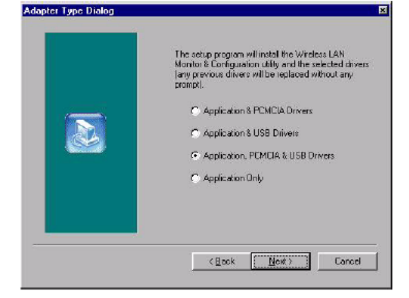
Figure 3-1. Selection of adapter type
Application & PCMCIA Drivers:
• By selecting this installation option, you will install the Applications (Configuration &
Monitor Utility and Firmware Upagrade Utility) and the latest PCMCIA drivers. If the
PCMCIA drivers have been previously installed and they have not been uninstalled
prior to the new installation the new drivers will ovewrite the old ones without
prompting you.
Application & USB Drivers:
• By selecting this installation option, you will install the Applications (Configuration &
Monitor Utility and Firmware Upagrade Utility) and the latest USB (A) drivers. If the
USB (A) drivers have been previously installed and they have not been uninstalled
prior to the new installation the new drivers will ovewrite the old ones without
prompting you.
Application, PCMCIA & USB Drivers:
• By selecting this installation option, you will install the Applications (Configuration &
Monitor Utility and Firmware Upagrade Utility) and the latest PCMCIA & USB (A)
drivers. If the PCMCIA & USB (A) drivers have been previously installed and they
have not been uninstalled prior to the new installation the new drivers will ovewrite the
old ones without prompting you.
Application Only:
• By selecting this installation option, you will only install the Applications (Configuration
& Monitor Utility and Firmware Upagrade Utility).
4. After you have assigned the Destination Location option where the application
will be installed (by Default this option is set to C:\Program Files\ATMEL\802.11
Wireless LAN), you can then choose the mode of operation:
3a. Ad-Hoc (Figure 3-2, Figure 3-3)
3b. Infrastucture (Figure 3-4, Figure 3-5).
Ad-Hoc Mode
In Ad-Hoc Mode the wireless stations can directly communicate with each other.
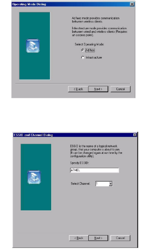
Figure 3-2. Operating Mode Dialog
When selecting the Ad-Hoc mode you have to specify the ESSID and the Channel
parameters (Figure 3-3).
• ESSID: Select the ESSID of the Ad-Hoc network. All stations participating in the Ad-
Hoc network should have the same ESSID.
• Channel: Select the channel to be used. There are 14 channels available.
Figure 3-3. ESSID and Channel Dialog
As soon as you have set your selections, press the “Next” button and a window appears
with a review of your installation settings. Please make sure that these values are the
desired ones. In case you have made a mistake you can always select the “Back” button
to make a correction. Press the “Next” button to continue with the installation, and finally
select the “Finish” button for the installation to be completed.
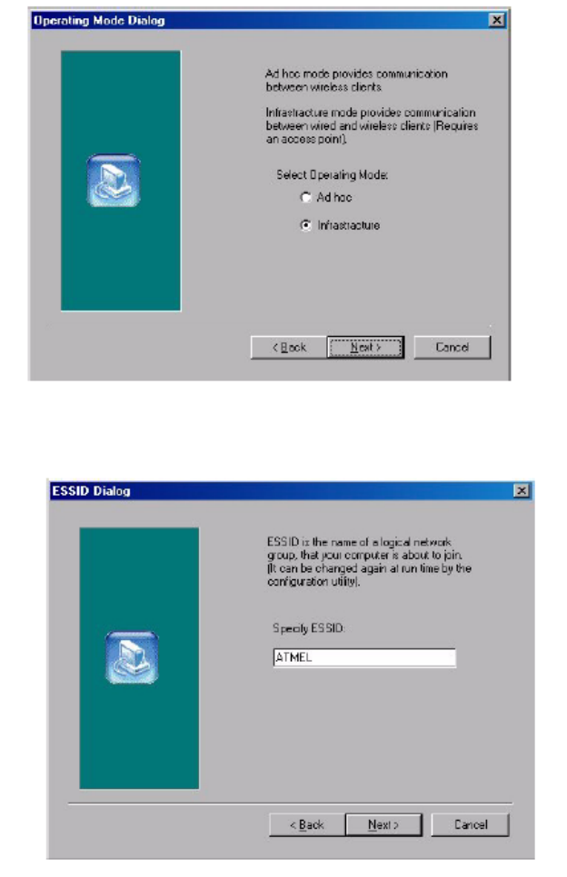
Infrastructure Mode
In Infrastructure Mode the use of an Access Point is necessary in order for the wireless
clients to communicate with each other.
Figure 3-4. Operating Mode Dialog
When selecting the Infrastructure mode you need to specify the ESSID (Figure 3-5).
• ESSID: Select the ESSID of the access point to which the wireless station will be
associated with in infrastructure mode.
Figure 3-5. ESSID Dialog
As soon as you have set your selections, press the “Next” button and a window appears
with a review of your installation settings. Please make sure that these values are the
desired ones. In case you have made a mistake, you can always select the “Back” button
to make a correction. Press the “Next” button to continue with the installation, and finally
press the “Finish” button for the installation to be completed.
Notes: 1. You can now safely plug your PCMCIA card. The “Add New Hardware Wizard”
automatically loads the Drivers for your PCMCIA card. As soon as the
procedure has been completed.
2. In the Windows 2000 installation procedure an extra window appears
prompting you to select whether you would like to install the “Digital Signature
Not Found” or not. You can safely select “YES”.
3.4 Uninstall
Procedure Under
Windows 98/Me
In order to uninstall the Configuration & Monitor Utility from Windows 98/Me, you must
select the “Unistall Configuration & Monitor Utility” option (Start -> Programs -> Atmel
802.11 Wireless LAN -> Unistall Configuration & Monitor Utility). It is recommended to
stop the PCMCIA card and “Exit” the application prior to starting the unistallation procedure.
If during the unistall procedure you receive an error message, please insert the
CD which contains the setup program and try to uninstall the Utility again.
The above procedure uninstalls the Configuration & Monitor Utility, but not the card
itself. In order to uninstall the Fast-VNET card from Windows 98/Me, you must double
click on the “Network” option in the “Control Panel” (Start -> Settings -> Control Panel).
Select the “ATMEL PCMCIA FastVNET (A)” card from the list and press the “Remove” button.
The system will prompt you to re-boot. Press "Yes" to re-boot.
3.5 Uninstall
Procedure Under
Windows 2000
The procedure in order to remove the Monitor & Configuration Utility is the same with the
one described for Windows 98/Me.
In order to uninstall the Fast-VNET card from Windows 2000 you must select it in the
Device Manager of Windows 2000 and press “Uninstall”. The “Uninstall” procedure
can be performed only if the Fast-VNET card is plugged in.

Section 4
Configuration & Monitor Utility
The Configuration & Monitor Utility is a powerful application that helps you to configure
the Fast-VNET card and monitor the statistics of the communication. Unlike the standard
method of configuring the card via the operating system utilities (e.g. Control
Panel), this application permits the dynamic modification of the configuration parameters
while the card is operating. It also offers some more configuration options.
ATMEL offers the Configuration & Monitor Utility for Windows 98/Me/2000.
Note: Please keep in mind that the Configuration & Monitor Utility can be used to
change the above configuration parameters when the cards are active. When
the cards are not in use, please use the Control Panel method described in previous
sections.
4.1 How to Install the
Configuration &
Monitor Utility
In order to setup the Configuration & Monitor Utility run the program “setup.exe,” which
you will find in your installation CD and follow the instructions as they appear on the
screen (see section 3). As soon as a link is established, the application will start running
and will appear as an icon on the system tray. You can locate the application under Start
-> Programs -> ATMEL 802.11 Wireless LAN -> Configuration & Monitor Utility.
4.2 Using the
Configuration &
Monitor Utility
The Configuration & Monitor Utility appears as an icon on the system tray of Windows
every time the card is running (see Figure 4-1). You can open it by double-clicking on
this icon. While the station is in infrastructure mode and not associated to an access
point, the color of the icon is red. As soon as the station associates itself to an Access
Point (see page 4-4 “Site Survey”), the icon color automatically turns to blue. In Ad-Hoc
mode the color is always blue, except when the card is resetting and Initialising where it
turns to red during the reset and initialisation procedure.
Figure 4-1. The icon of the Configuration and Monitor Utility
When the application is opened the following options (tabs) are available:
• Monitor
• Statistics
• Site Survey
• Encryption
• Advanced
• Version
Note: Please Note that at the very top of the Monitor and Configuration Utility of
the application (Figure 4-2), you can either select ATMEL PCMCIA FastVNET
(3.3V) or ATMEL USB (A) FastVNET card.
Monitor
A typical screen of the application in Infrastructure mode is shown in Figure 4-2. The
configuration parameters are shown at the top of the screen (Operation Mode, Channel,
SSID, TxRate, Power Management Mode and MAC Address of the USB card). In the
middle of the screen there is information about the status of the communication (the
BSSID of the Access Point to which the card is associated, Signal Strength, and Link
Quality). In order to change the configuration parameters press the “Change” button,
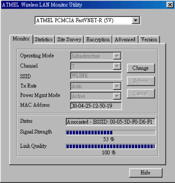
make your changes and then press “Submit” in order to save your changes.
Figure 4-2. A typical screen of the Monitor Utility in Infrastructure mode.
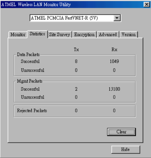
Statistics
This option enables you to view the available statistic information (Data packets, Management
Packets and Rejected packets). In order to renew or update this list of
statistics, press the “Clear” button. In order to exit press the “Exit” button at the bottom of
the screen.
Figure 4-3. Stastic information available
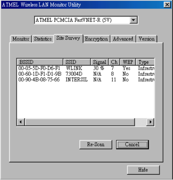
Site Survey
By choosing the Site Survey option in any of the two modes, you can scan all the channels
in order to find all the access points within the range of your card. In Figure 4-4, the
card can see four access points. The list includes information about the BSSID and
SSID of the access point(s), the signal strength, the channel where the access point(s)
operates, and whether or not WEP encryption is used. In order to update this list, press
the “Rescan” button. If you want to associate with any of the access point(s) listed, double
click on your choice (on the BSSID field), and the system will take you back to the
Monitor screen showing you the parameters of the connection newly established.
Figure 4-4. Site Survey Option
Encryption
By choosing this option in any of the two modes, you can set four different WEP keys
and specify which one of them to use. First, either enable or disable encryprion from the
appropriate “Encryption” field (see Figure 4-5 below). If you decide to use encryption,
you can choose any of the available WEP keys (1 to 4). You also have the option to
select the WEP mode (Mandatory/Optional). If you select “Mandatory”, then not only
WEP will be used, but also any other station needs to use WEP encryption in order to
establish a communication with your station. This requirement is in line with the IEEE
802.11b standard. If, on the other hand, you choose “Optional”, then your station can
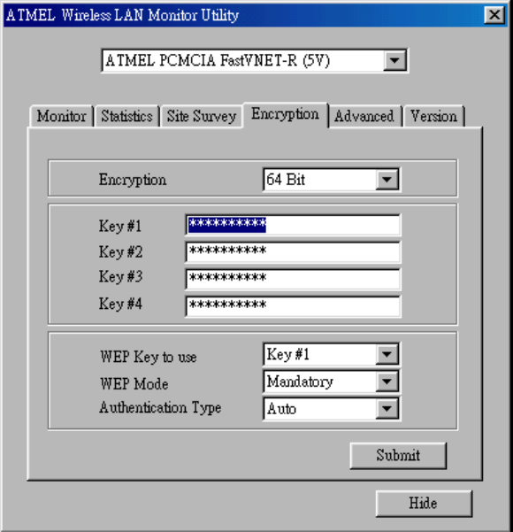
communicate with every other station regardless if they use WEP or not. Please keep in
mind that the WEP keys must be in HEX format. Finally, you have the option to select
whether Open System or Shared Key authentication will be used. In order to take effect
the changes you wish to make, press the “Submit” button at the bottom of the screen.
Figure 4-5. Encryption
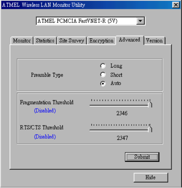
Advanced
By Choosing the Advanced option in any of the two modes, you can change advanced
configuration settings, such as the Preamble Type, Fragmentation Threshold, and
RTS/CTS Threshold (Figure 4-6). Figure 4-5 shows the recommended configuration for
the advanced settings. Before selecting Short Preamble, make sure that the other stations
and APs are also supporting this feature.
Note: The USB (A) card has an auto-detection feature therefore it automaticatilly
selects the Preable Type depending on the Access Point Preamble type. In
order to enable the Fragmentation and the RTS/CTS Threshold parameters
move the slide bar with your mouse and then use the right and left arrow keys of
your keyboard in order to select an exact number.
Figure 4-6. Advanced Settings
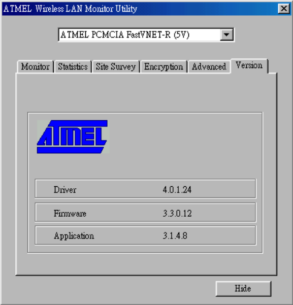
Version
By choosing this option, you can view basic information about the Utility like the Driver,
Firmware and Application Version. Use the “Exit” button in order to exit the application.
Figure 4-7. Version information
4.3 How to Uninstall
the
Configuration &
Monitor Utility
In order to uninstall the Configuration & Monitor Utility, you must select the “Unistall
Configuration & Monitor Utility” option (Start -> Programs -> Atmel 802.11 Wireless LAN
-> Unistall Configuration & Monitor Utility). It is recommended to “Exit” the Configuration
& Monitor Utility prior to starting the unistallation procedure. Finally a window will appear
prompting you to reboot and you must select YES.
Section 5
Firmware Upgrade Utility
For the Fast-VNET PCMCIA cards, ATMEL offers a firmware utility which is a Windows
application (Firmware Upgrade utility) that allows you to upgrade the firmware of your
card while your card is running.
5.1 Firmware
Upgrade Utility
Note: Please DO NOT use this utility unless you have got new binary files from
ATMEL. If you use this utility and you do not supply the correct binary file, you
may damage your card.
The Firmware Upgrade utility allows you to upgrade the firmware of your card while your
card is running. It will download the new firmware and it will reset your card in order to
start operating with the new firmware.
ATMEL offers the Firmware Upgrade Utility for Windows 98, Windows Me, Windows
2000.
The Firmware Upgrade Utility is automatically installed when you run the program
“setup.exe” of you installation CD (see Section 4- “How to install the Configuration &
Monitor Utility”). Locate the program from the Start Menu -> Programs -> ATMEL
802.11Wireless LAN -> Firmware Upgrade Utility. When you open the program, you will
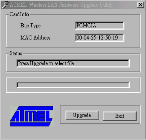
see the main screen of Figure 5-1.
Figure 5-1. The ATMEL PCMCIA Firmware Upgrade Utility
Press the “Upgrade” button in order for a file selection window to appear. Browse for the
xxxx.rom file that contains the new firmware. After you have located and selected the
file, the firmware upgrade process will begin (Figure 5-2).
Figure 5-2. Upgrading the firmware
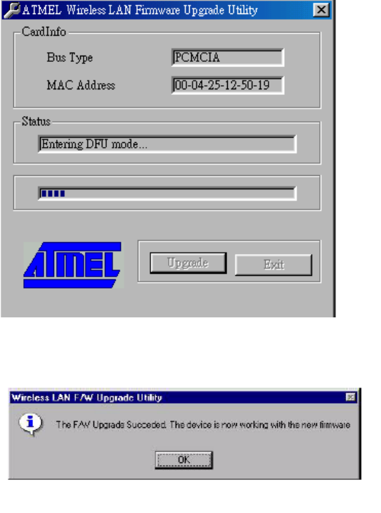
When the firmware has been upgraded, you will see a notification from the Firmware
Upgrade Utility (Figure 5-3). Press “OK” to complete the upgrade.
Figure 5-3. Completion of the firmware upgrade procedure
Federal Communication Commission Interference Statement
This equipment has been tested and found to comply with the limits for a Class B digital device,
pursuant to Part 15 of the FCC Rules. These limits are designed to provide reasonable
protection against harmful interference in a residential installation. This equipment generates,
uses and can radiate radio frequency energy and, if not installed and used in accordance with
the instructions, may cause harmful interference to radio communications. However, there is no
guarantee that interference will not occur in a particular installation. If this equipment does cause
harmful interference to radio or television reception, which can be determined by turning the
equipment off and on, the user is encouraged to try to correct the interference by one of the
following measures:
- Reorient or relocate the receiving antenna.
- Increase the separation between the equipment and receiver.
- Connect the equipment into an outlet on a circuit different from that to which the receiver is
connected.
- Consult the dealer or an experienced radio/TV technician for help.
FCC Caution: To assure continued compliance, (example - use only shielded interface cables
when connecting to computer or peripheral devices) any changes or modifications not expressly
approved by the party responsible for compliance could void the user's authority to operate this
equipment.
This device complies with Part 15 of the FCC Rules. Operation is subject to the following two
conditions: (1) This device may not cause harmful interference, and (2) this device must accept
any interference received, including interference that may cause undesired operation.
IMPORTANT NOTE:
FCC Radiation Exposure Statement:
This equipment complies with FCC radiation exposure limits set forth for an uncontrolled
environment. This equipment should be installed and operated with minimum distance 2.5cm
between the radiator & your body.
This transmitter must not be co-located or operating in conjunction with any other antenna or
transmitter.