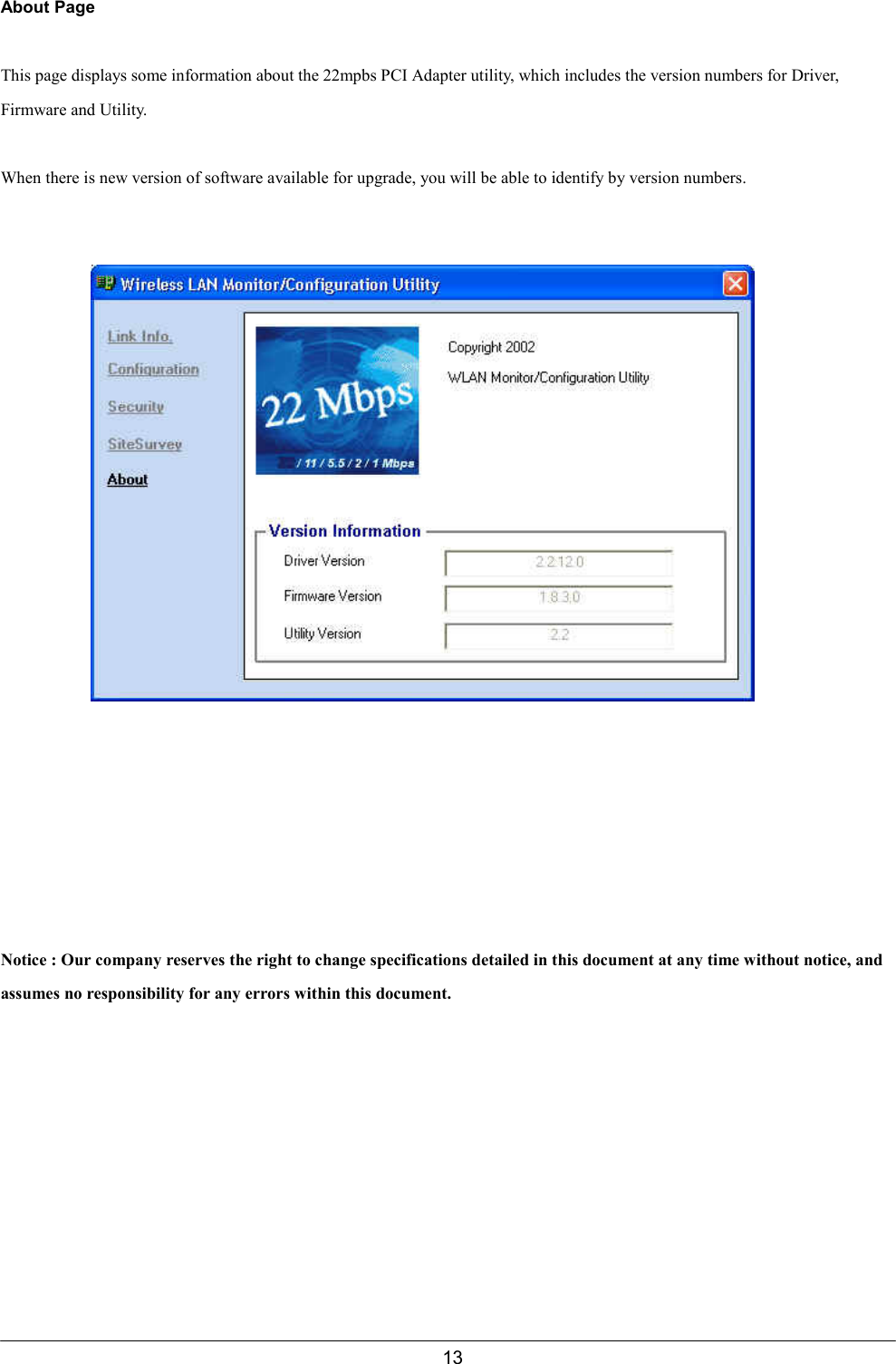
D Link ACX100 Wireless 22Mbps Mini PCI Card User Manual Manual

D Link Corporation Wireless 22Mbps Mini PCI Card Manual

Manual

1CONTENTS1. PRODUCT GENERAL INFORMATION..……………………………………………..….21.1. Product Description…………………………………………………………………………………….21.2. Product Feature…………………………………………...……………………………………………21.3. Product Application………………………………………………………….……………………………..22. PRODUCT GENERAL………………………………………………………………….….32.1. General Specifications………………………….………………..…………………………..… 32.2. LED Indicator………………………………………………………..…………..….………………32.3. Interface………………………………………………………….…….………………………..…..33. PRODUCT HARDWARE SPECIFICATION……………………….………………….….33.1. RF Specification…………………………………………………….………….….…………………..….33.1.1. General……………………………………………………….………………..………………..33.1.2. Transmitter…………………………………………………….…………..……………………33.1.3. Receiver…………………………………………………………………..……………………43.1.4. Antenna Type………………………………………………….…………..…………………...43.1.5. Typical Operating Range………………………………………….………..…………………43.2. H/W Specification………………………………………………………….…………………………....43.2.1. MAC Controller.…………………………………………………….……..……………………43.2.2. Memory.……………………………………………………………….…..…………………….43.2.3. Power……………………………………………………………………....……………………44. PRODUCT SOFTWARE SPECIFICATION………………………………….……...……44.1. Driver…………………………….……………………………...……………..……………………..…..44.2. Configuration Utility………………..…………………………….………..………………………..….45. PRODUCT COMPLIANCE………………………………………………………….……..56. OPERATING CONDITION……………………………………………………..……..56.1. Drop and Vibration test……………………………….……………………………...……….56.1.1. Anti-Static Voltage……………………………………………………………………..………..56.1.2. Vibration Test………………………………………………………..…………….….………..56.1.3. Package Drop Test……………………………………………………………….…..…………56.2. Operation Environment ……………………………………………………………………...……….…56.2.1. Temperature Range………………………………………………………………….…………5     6.2.2. Reliability Test…………………………………………………….…………….56.2.3. Humidity…….…………………………………………..…………………………………….….57. INSTALLATION AND CONFIGURATION……………………..………………..……..67.1. Installation………….……………………………….……………………………...……….67.2. Configuration……………………………………………………………………………...……….…6
2WLAN 22Mbps MiniPCI Card1. Product General Information1.1. Product DescriptionGL2422MP, the wireless Ethernet adapter for mini PCI type IIIB compliantnotebook PCs, set-top box and integrated device, is fully compatible withIEEE 802.11b standard and supporting higher data rate to 22Mbps. UsingDirect Sequence spread spectrum technology for immunity from interference,it will automatically fallback to lower data rate in the environment ofinterference.22Mbps data rate is designed by the Packet Binary Convolution Code (PBCC) modulation technique. The software supportsWindows OS such as Win98, Win2000, Win ME, and Win XP. The Mini PCI card for any integrated device is designed with U.FLor MMCX connector to conduce high performance for integrated product.1.2. Product Feature● IEEE 802.11b Direct Sequence high rate compatible.● Based on DSSS Technology and support the modulation of PBCC mode● High-Speed wireless connection up to 22Mbps data rate, and support 11/5.5/2/1 Mbps 802.11b standard● Advanced Power Management supports power saving mode for battery device● Auto fallback data rate in the environment of interference.● 64/128/256 Bits WEP Encryption function● High through-put supports multi-Media data bandwidth requirement● Plug-and-play Installation● Support Mini PCI type IIIB interface1.3. Product Application● Wireless Networking in Enterprise, SOHO and home environment● Wireless Networking Access in Hot Spot area such as Airport, Hotel, School, Convention center, Coffee shop, etc…● Mobile media through wireless LAN● Mobile networking for notebook PC, and mobile devices● Build system in Ad-Hoc for Host-Client appliance or Infrastructure mode for multi-access
32. PRODUCT GENERAL2.1. General SpecificationsStandards: IEEE802.11b CompliantMini PCI standard Type-III-BData Rate: 22Mbps / 11Mbps / 5.5 Mbps / 2Mbps / 1 Mbps auto fallbackSecurity: 64/128/256 bit Wired Equivalent Privacy (WEP)Dimension           59.75 mm (L) X 44.6 mm (W) X 4. 8 mm (H)2.2. LED Signal Support      2 Pin (For Power/Status, Tx/Rx)--LED signal supporting2.3. Interface              Mini PCI Type – III- B3. PRODUCT HARDWARE SPECIFICATIONS3.1. RF Specification3.1.1 GeneralEmission Type Direct Sequence Spread Spectrum (DSSS)RF Frequency 2400MHz – 2497 MHz – Japan Band2400MHz – 2483.5MHz – North America, Europe2446.5MHz – 2483.5MHz – FranceOperating Channel       11 Channels (US, Canada)13 Channels (Europe)14 Channels (Japan)Radio Chipset: RFMDMedia Access CSMA/CA (Collision Avoidance) with ACK3.1.2 TransmitterRF Output Power 18 dBm    (Typ. )Frequency Stability            Within + 25 ppmData modulation type PBCC/CCK/QPSK/BPSKData modulation speed 22/11/5.5/2/1 Mbps with auto fallback   3.1.3 ReceiverSensitivity -80 dBm @ 22Mbps (Typically @25℃+5℃)(Less than 8% of PER packet sizes is 1024 bytes)
43.1.4 Antenna ConnecterBuilt-in one or two HRS U.FL or MMCX type connector3.1.5. Typical Operation Range        22Mbps                100M11Mbps                   150M5.5Mbps                  250M2Mbps                   300M1Mbps                   350M3.2. Hardware Specification 3.2.1. Bus Interface            PCI I/O port                32 Bit3.2.2. MAC Controller          MAC                      ACX100A3.2.3. MemoryEEPROM 8 Kbytes3.2.4. PowerPower Voltage 3.3v + 5%Power Consumption 650mA by TX    (Max.)350mA by RXStand by mode TBDSleeping mode TBD4. PRODUCT SOFTWARE SPECIFICATION4.1. DriverNDIS 4.0 LAN driver Win98, NDIS5.0 LAN driver for Win2000 & Win ME, NDIS 5.1 LAN for Win XP4.2. Configuration UtilityConfiguration Utility software program for Win/98, Win2000, Win ME, Win XPConfigurable Parameters DescriptionNetworking Type Infrastructure / Ad-HocChannel Channel number setting (14 channels available)ESSID ESSID settingRx Rate Current Receiving data rateTX Rate Current Transmitting rate
5WEP Disable, 64 bit, 128 bit and 256 bitLink Quality Receiving AP link quality on infrastructureSignal Strength Receiving AP signal strength on infrastructure5. REGULATION COMPLIANCECompliant withFCC Part 15 Class B and CETSI EN 300 328-2 and ETSI EN 301 489-1, -17, EN60950, CE-MarkTelec (Japan, Customized)WiFi Compliant6. Environmental Requirement6.1. Drop and Vibration 6.1.1. Anti-Static VoltageStatic voltage tests by 4 kV in card frame should not cause system fail. 6.1.2. Vibration TestThe vibration test is under the frequency and amplitude 10-25 Hz 1mm in vertical and horizontal direction by 30minutes that should not cause any damage on product.6.1.3. Package Drop TestDropping the package from the height of 50cm for each of the six (6) faces onto the hardwood floor should not causeany damage on product.6.2. Operation Environment6.2.1. Temperature RangeOperating: -0℃ - +50℃  (Except RF output power and sensitivity)Storage: -20℃ - +70℃6.2.2. Reliability TestOne cycle of reliability test is keeping at -30℃  by 2 hours, switching temperature up to +60℃  within one hour , andtesting at +60℃  by 2 hours, and switching temperature to -30℃  within one hour. Three cycle should be tested and
6without any product fail.6.2.3. HumidityOperating: 0% to 70%Storage 0% to 95% Non-condensing  7. INSTALLATION AND CONFIGURATION7.1. Installation1. Start the computer2. Insert 22Mbps driver CD into the CD-ROM3. Select “PC Card/PCI Card”4. Click “Install “ button.5. Click “Next” button.6. Click “Finish” button to restart computer.
77. Shut down the computer then insert MiniPCI Card into the MiniPCI slot of computer.8. Restart computer7.2. Configuration1. Double Click “ ” icon in the right hand corner of the screen.2. The window of “Link Information” show the current status of wireless mini PCI Card.Link Info. Page
8This is the default page when the utility starts up.Status: Shows the BSSID associated, which can be used to identify the wireless network.SSID: Shows current SSID, which must be the same for the wireless client and AP in order for communication to be established.TxRate: Shows the current data rate used for transmitting.Channel: Shows the current channel for communication.Radio Off button: When clicked, you disable the radio signal, and cut-off the wireless connection.Link Quality: Shows the link quality of the 22Mbps wireless Network PCI Adapter with the Access Point when operating underInfrastructure mode.Signal Strength: Shows the wireless signal strength of the connection between the 22mpbs wireless Network PCI Adapter with theAccess Point.Data Rate: Shows the statistics of data transfer, and the calculation is based on the number of packets transmitted and received.Configuration PageThis is the page where you can change the basic settings of the Access Point with the minimum amount of effort to adjust a securewireless network.SSID: Service Set Identifier, which is a unique name shared among all clients and nodes in a wireless network. The SSID must beidentical for each clients and nodes in the wireless network.BSS Type: There are two types available for selectionz Infrastructure – to establish wireless communication with LAN and other wireless clients through the use the AccessPoints.z Ad-Hoc – to establish point-to-point wireless communication directly with other wireless client devices such as
9wireless network PCI Adapter.Channel: The value of channel that AP will operate in. You can select the channel range of 1 to 11 for North America (FCC)domain, 1 to 13 for European (ETSI) domain and 1 to 14 for Japanese domain.Tx Rate: Select the data rate for data transmission.Preamble: Select Long or Short Preamble type. Preamble is a sequence of bits transmitted at 1Mbps that allows the PHY circuitryto reach steady-state demodulation and synchronization of bit clock and frame start. Two different preambles and headers aredefined: the mandatory supported Long Preamble and header, which interoperates with the 1 Mbit/s and 2 Mbit/s DSSS specification(as described in IEEE Std 802.11), and an optional Short Preamble and header (as described in IEEE Std 802.11b). At the receiver,the Preamble and header are processed to aid in demodulation and delivery of the PSDU. The Short Preamble and header may beused to minimize overhead and, thus, maximize the network data throughput. However, the Short Preamble is supported only fromthe IEEE 802.11b (High-Rate) standard and not from the original IEEE 802.11. That means that stations using Short-Preamblecannot communicate with stations implementing the original version of the protocol.Power Mode: There are 3 modes to choose fromz Continuous Access Mode (default) – the PCI Adapter is constantly operating with full power and it consumes the mostpowerz Maximum Power Save – the PCI Adapter consumes the least power and only operates when there is wireless networkactivity.z Power Save – the PCI Adapter consumes the moderate level of power.For the changes made to any of the items above to be effective, click “Apply”.    The screen will be changed back to Link Info.Page
10Security PageThis is the page where you configure Security settings of your 22Mbps wireless PCI Adapter.Data Encryption: Click the box to enable Data Encryption feature.Aut. Mode: There are three modes available to choose from.z Open Authentication – the sender and receiver do not share secret Key for communication. Instead, each partygenerates its own key-pairs and ask the other party to accept it. The key is regenerated when the connection isestablished every time.z Shared Authentication – the sender and receiver shares the common key for data communication, and the key is usedfor extended length of time.z Auto – depend on the communication to establish, and automatically use the proper authentication mode.The following will only be activated to allow for configuration when Data Encryption is enabled.Default Key: select one of the 4 keys to use.Network Key: enter values to these fields, either in HEX or ASCII formats. You only have to enter the key that you will useKey Length: select 64, 128 or 256 bits as the length of the keysKey Format: ASCII or HEX (Please refer to Appendix G: Glossary for details about these two formats).
11SiteSurvey PageThis page allows to utilize the SiteSurvey function to scan for the available wireless network (wireless clients and Access Points)and select one to establish wireless communication.Available Network – displays the wireless networks (wireless clients and Access Points) that are in your signal range. Selectany one of them and establish communication by simply mouse double-click or a single click on the “Connect” button.Click “Refresh” button to start scanning for available network again.Profile – You can create and manage the created profiles for Home, offices or public areas.By double-clicking on one of the created profile, the setting will adapt to the configuration such as SSID, channel, and WEPsettings saved by that particular profile.Click to select any one of the profiles, and you canClick on “Remove” button to remove the profile, orClick on “Properties” button to view and change its settings. The Properties is very similar to that of adding profile.Click “Add” to add a profile, and the following screen would appear.1122
12All the detail information about each settings and configuration item are described in previous Configuration and Security Pagesessions. Please refer to those two sessions for more information.When you finish enter the setting for this profile, click “OK” to add a new profile.
13About PageThis page displays some information about the 22mpbs PCI Adapter utility, which includes the version numbers for Driver,Firmware and Utility.When there is new version of software available for upgrade, you will be able to identify by version numbers.Notice : Our company reserves the right to change specifications detailed in this document at any time without notice, andassumes no responsibility for any errors within this document.
14Federal Communication Commission Interference StatementThis equipment has been tested and found to comply with the limits for a Class B digital device, pursuant to Part 15 of the FCCRules. These limits are designed to provide reasonable protection against harmful interference in a residential installation. Thisequipment generates, uses and can radiate radio frequency energy and, if t not installed and used in accordance with theinstructions, may cause harmful interference to radio communications. However, there is no guarantee that interference will notoccur in a particular installation.    If this equipment does cause harmful interference to radio or television reception, which can bedetermined by during the equipment off and on, the user is encouraged to try to correct the interference by one or more of thefollowing measures:¾ Reorient or relocate the receiving antenna.¾ Increase the separation between the equipment and receiver.¾ Connect the equipment to an outlet on a circuit different from that to which the receiver is connected.¾ Consult the dealer or an experienced radio/TV technician for help.FCC Caution: Any changes or modifications not expressly approved by the party responsible for compliance could void the user'sauthority to operate this equipment.This device complies with Part 15 of the FCC rules. Operation is subject to the following two conditions: (1) This device may notcause harmful interference, and (2) this device must accept any interference received, including interference that may causeundesired operation.IMPORTANT NOTE:FCC Radiation Exposure Statement:This equipment complies with FCC radiation exposure limits set forth for an uncontrolled environment. Thisequipment should be installed and operated with minimum distance 20cm between the radiator & your body.This transmitter must not be co-located or operating in conjunction with any other antenna or transmitter.This device is intended only for OEM integrators under the following conditions:The antenna must be installed such that 20 cm is maintained between the antenna and users, andThe transmitter module may not be co-located with any other transmitter or antenna.As long as 2 conditions above are met, further transmitter test will not be required. However, the OEM integrator isstill responsible for testing their end-product for any additional compliance requirements required with this moduleinstalled (for example, digital device emissions, PC peripheral requirements, etc.).IMPORTANT NOTE: In the event that these conditions can not be met (for example certain laptop configurations orco-location with another transmitter), then the FCC authorization is no longer considered valid and the FCC ID can notbe used on the final product. In these circumstances, the OEM integrator will be responsible for re-evaluating the endproduct (including the transmitter) and obtaining a separate FCC authorization.
15End Product LabelingThis transmitter module is authorized only for use in device where the antenna may be installed such that 20 cm maybe maintained between the antenna and users (for example: Wireless Router, Wireless Access Point, VP). The final endproduct must be labeled in a visible area with the following: “Contains TX FCC ID: KA2ACX100 ”.Manual Information That Must be IncludedThe OEM integrator has to be aware not to provide information to the end user regarding how to install or remove thisRF module in the users manual of the end product which integrate this module.The users manual for OEM integrators must include the following information in a prominent location “ IMPORTANTNOTE: To comply with FCC RF exposure compliance requirements, the antenna used for this transmitter must beinstalled to provide a separation distance of at least 20 cm from all persons and must not be co-located or operating inconjunction with any other antenna or transmitter.

Navigation menu