D Link AP1250A1 Wireless LAN Access Point User Manual DAP 1250QIG for EMI
D Link Corporation Wireless LAN Access Point DAP 1250QIG for EMI
D Link >
Manual
DAP-1250
System Requirements
• A Network with 802.11g/b wireless devices
Package Contents
• Access Point
• Antenna
Please follow below table to install DAP-1250 , otherwise, it may be illegal.

Antenna No. Type Frequency Band Gain (dBi) Conntector cable
Length cable
loss
ANT24-0800 Dipole Omni 2400MHz
- 2500MHz 8 N female 7m 6
ANT24-1201 Yagi Directional 2400MHz
- 2500MHz 12 N female or
SMA femal 11.7m 10
ANT24-1400 Panel Directional 2300MHz
- 2500MHz 14 N female 14m 12
ANT24-1800 Panel Directional 2400MHz
- 2500MHz 18 N female 18.7m 16
ANT24-1801 Yagi Directional 2400MHz
- 2700MHz 18 N female 18.7m 16
ANT70-0800 Dipole Omni
2400MHz
- 2500MHz
4900MHz
- 5470MHz
8
8 N Jack 7m 6
6
ANT70-0801 Dipole Omni
2400MHz
- 2500MHz
4900MHz
- 5470MHz
8
8 N Jack 7m 6
6
ANT70-1000 Panel Directional
2400MHz
- 2500MHz
4900MHz
- 5875MHz
8
10 N Jack 7m 6
8
WSS002 1/4 入 Dipole 2400MHz
- 2500MHz 2 RP-SMA(M) 0 0
N/A Printed 2400MHz
- 2500MHz 2 N/A N/A N/A
• CD-ROM (with software, manual, and warranty)
• Ethernet Cable
• 5V/2A Power Adapter
• Rubber Feet
• A Network with 802.11g/b wireless devices
Before You Begin
It’s best to use a computer (with an Ethernet adapter) that is connected to a
switch or router for configuring the DAP-1250. The default IP address for the
DAP-1250 is 192.168.0.50 with a Subnet Mask of 255.255.255.0.
You will need to assign your computer a Static IP address within the same
range as the DAP-1250’s IP address for the purpose of configuring the
DAP-1250. See the Appendix if you need assistance in assigning a Static IP
address for your network adapter.
Installation Considerations
D-Link wireless devices allow you access your network using a wireless
connection from virtually anywhere within the operating range of your wireless
network. Keep in mind, however, that the number, thickness and location of
walls, ceilings, or other objects that the wireless signals must pass through,
may limit the range. Typical ranges vary depending on the types of materials
and background RF (radio frequency) noise in your home or business. The key
to maximizing wireless range is to follow these basic guidelines:
1. Keep the number of walls and ceilings between the D-Link access point
and other network devices to a minimum - each wall or ceiling can reduce
your adapter’s range from 3-90 feet (1-30 meters.) Position your devices
so that the number of walls or ceilings is minimized.
2. Be aware of the direct line between network devices. A wall that is 1.5
feet thick (.5 meters), at a 45-degree angle appears to be almost 3 feet (1
meter) thick. At a 2-degree angle it looks over 42 feet (14 meters) thick!
Position devices so that the signal will travel straight through a wall or
ceiling (instead of at an angle) for better reception.
3. Building Materials make a difference. A solid metal door or aluminum
studs may have a negative effect on range. Try to position access points,
wireless routers, and computers so that the signal passes through drywall
or open doorways. Materials and objects such as glass, steel, metal, walls
with insulation, water (fish tanks), mirrors, file cabinets, brick, and concrete
will degrade your wireless signal.
4. Keep your product away (at least 3-6 feet or 1-2 meters) from electrical
devices or appliances that generate RF noise.
5. If you are using 2.4GHz cordless phones or X-10 (wireless products such as
ceiling fans, lights, and home security systems), your wireless connection
may degrade dramatically or drop completely. Make sure your 2.4GHz
phone base is as far away from your wireless devices as possible. The
base transmits a signal even if the phone in not in use.
Connecting the DAP-1250 Wireless
Access Point to Your Network
A. First, connect the power adapter to the receptor at the back panel of the
DAP-1250 and then plug the other end of the power adapter to a wall outlet
or power strip. The Power LED will turn ON to indicate proper operation.
B. Insert one end of the cable to the Ethernet port on the back panel of the
DAP-1250 and the other end of the cable to your network (switch or router).
Note: You also have the option of connecting the DAP-1250 directly to the
computer that will be used for configuration. The Link LED light will illuminate
to indicate a proper Ethernet connection.
C. The DWL-G650 AirPlus Xtreme G Wireless Cardbus Adapter and the
DWL-G520 AirPlus Xtreme G Wireless PCI Adapter will connect, out of the box,
with the DAP-1250, using their default wireless settings. Computers with
802.11b wireless adapters can also connect to the DAP-1250.
Setup Wizard
1.Open your Web browser and type http://192.168.0.50 into the
URL address box. Then press the Enter or Return key.
2.Type admin for the username and leave the password field blank.
Click OK
3. Once you have logged in, the Home screen will appear. Click Run Wizard
4. Then check next and follow the next steps
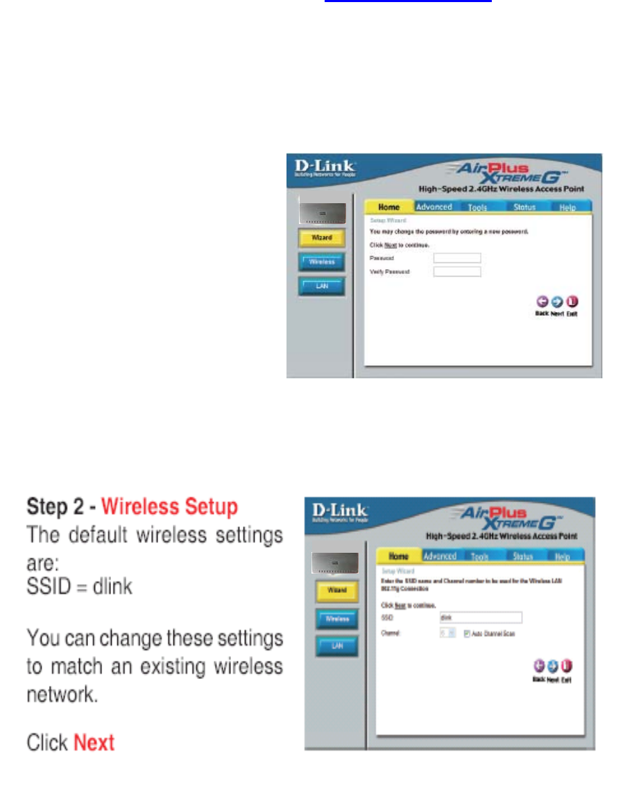
Step 1 - Set up your new password.
You have the option to establish a
password.
Click Next
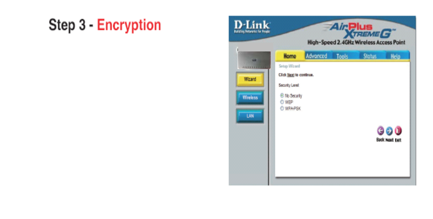
Step 3 - Encryption
The DAP-1250 is capable of two levels
of wireless encryption WEP and
WPA-PSK. By default the encryption is
disabled. You can change the
encryption settings for more secure
wireless communication.
Click Next
Then Click Restart
Your Setup is Complete!

Technical Support
D-Link’s website contains the latest user documentation and software
updates for D-Link products.
U.S. and Canadian customers can contact D-Link Technical Support
through our website or by phone.
Copyright c 00 D-Link Corporation/D-Link Systems, Inc. All rights reserved.
D-Link and the D-Link logo are registered trademarks of D-Link Corporation or
its subsidiaries in the United States and other countries. Other trademarks are
the property of their respective owners. Maximum wireless signal rate derived
from IEEE Standard 0 .11g specifications. Actual data throughput will vary.
Network conditions and environmental factors, including volume of network
traffic, building materials and construction, and network overhead, lower actual
data throughput rate. Environmental factors may adversely affect wireless
signal range. Visit www.dlink.com for more details.
Industry Canada Statement
This device complies with RSS-210 of the Industry Canada Rules. Operation is
subject to the following two conditions:
1) this device may not cause interference and
2) this device must accept any interference, including interference that may
cause undesired operation of the device
This device has been designed to operate with an antenna having a maximum
gain of .. 2dBi.
Antenna having a higher gain is strictly prohibited per regulations of Industry
Canada. The required antenna
impedance is 50 ohms.
To reduce potential radio interference to other users, the antenna type and its
gain should be so chosen that the EIRP is not more than required for
successful communication.
IMPORTANT NOTE:
IC Radiation Exposure Statement:
This equipment complies with IC radiation exposure limits set forth for an
uncontrolled environment. This equipment should be installed and operated
with minimum distance 20cm between the radiator & your body.
Federal Communication Commission Interference Statement
This equipment has been tested and found to comply with the limits for a Class
B digital device, pursuant to Part 15 of the FCC Rules. These limits are
designed to provide reasonable protection against harmful interference in a
residential installation. This equipment generates, uses and can radiate radio
frequency energy and, if not installed and used in accordance with the
instructions, may cause harmful interference to radio communications.
However, there is no guarantee that interference will not occur in a particular
installation. If this equipment does cause harmful interference to radio or
television reception, which can be determined by turning the equipment off and
on, the user is encouraged to try to correct the interference by one of the
following measures:
- Reorient or relocate the receiving antenna.
- Increase the separation between the equipment and receiver.
- Connect the equipment into an outlet on a circuit different from that
to which the receiver is connected.
- Consult the dealer or an experienced radio/TV technician for help.
This device complies with Part 15 of the FCC Rules. Operation is subject to the
following two conditions: (1) This device may not cause harmful interference,
and (2) this device must accept any interference received, including
interference that may cause undesired operation.
FCC Caution: Any changes or modifications not expressly approved by the
party responsible for compliance could void the user's authority to operate this
equipment.
IMPORTANT NOTE:
FCC Radiation Exposure Statement:
This equipment complies with FCC radiation exposure limits set forth for an
uncontrolled environment. This equipment should be installed and operated
with minimum distance 20cm between the radiator & your body.
This transmitter must not be co-located or operating in conjunction with any
other antenna or transmitter.
The availability of some specific channels and/or operational frequency bands
are country dependent and are firmware programmed at the factory to match
the intended destination. The firmware setting is not accessible by the end
user.
申請DGT使用手冊必須包含之資訊:
經型式認證合格之低功率射頻電機,非經許可,公司、商號或使用者均不得擅自
變更頻率、加大功率或變更原設計之特性及功能。
低功率射頻電機之使用不得影響飛航安全及干擾合法通信;經發現有干擾現象
時,應立即停用,並改善至無干擾時方得繼續使用。
前項合法通信,指依電信法規定作業之無線電通信。
低功率射頻電機須忍受合法通信或工業、科學及醫療用電波輻射性電機設備之干
擾。