D Link AP2553B1 Dual Band PoE Access Point User Manual
D Link Corporation Dual Band PoE Access Point
D Link >
User Manual.pdf

2D-Link DAP-2553 User Manual
Table of Contents
Product Overview .............................................................. 4
Package Contents ......................................................................... 4
System Requirements ................................................................. 4
Introduction ................................................................................... 5
Features ............................................................................................ 7
Wireless Basics ................................................................... 8
Standards-Based Technology ................................................... 9
Wireless Installation Considerations ....................................10
Hardware Overview ...................................................................11
Connect Power over Ethernet (PoE) .............................12
Four Operational Modes .................................................13
Getting Started ................................................................14
Conguration ................................................................... 15
Save and Activate Settings ......................................................16
Basic Settings ...............................................................................17
Wireless .................................................................................17
Access Point mode ........................................................17
WDS with AP mode ......................................................19
WDS mode .......................................................................21
Wireless Client mode ....................................................23
Open System/Shared Key Authentication ...........24
WPA/WPA2-Personal Authentication ......................25
WPA/WPA2-Enterprise Authentication ..................26
802.11x Authentication ...............................................27
LAN .........................................................................................28
IPv6 ..........................................................................................29
Advanced Settings .....................................................................30
Performance .........................................................................30
Wireless Resource Control ...............................................33
Multi-SSID ..............................................................................35
VLAN ........................................................................................37
VLAN List ...........................................................................37
Port List ..............................................................................38
Add/Edit VLAN ................................................................39
PVID Setting .....................................................................40
Intrusion .................................................................................41
Schedule ................................................................................42
Internal RADIUS Server .....................................................43
ARP Spoong Prevention ................................................44
Bandwidth Optimization .................................................45
AP Array ..................................................................................47
AP Array Scan ..................................................................47
Conguration Settings .................................................48
Wireless Basic Settings .................................................49
Wireless Advanced Settings .......................................49
Multiple SSID & VLAN ...................................................50
Advanced Functions .....................................................50
Administration Settings ..............................................51
Auto-RF .............................................................................. 52
Load Balance ...................................................................53
Captive Portal .......................................................................54
Authentication Settings - Passcode ........................54
Table of Contents

3D-Link DAP-2553 User Manual
Table of Contents
Authentication Settings - User Name/Password 55
Authentication Settings - Remote RADIUS ...........56
Authentication Settings - LDAP ................................57
Authentication Settings - POP3 ................................58
Login Page Upload ........................................................59
Web Redirection .............................................................60
DHCP Server ........................................................................61
Dynamic Pool Settings .................................................61
Static Pool Setting .........................................................63
Current IP Mapping List ...............................................65
Filters .......................................................................................66
Wireless MAC ACL ..........................................................66
WLAN Partition ...............................................................67
Trac Control .......................................................................68
Uplink/Downlink Setting ............................................68
QoS ...................................................................................... 69
Trac Manager ...............................................................70
Status .............................................................................................71
Device Information ............................................................71
Client Information ..............................................................72
WDS Information ................................................................73
Channel Analyze .................................................................74
Stats .........................................................................................75
Ethernet ............................................................................. 75
WLAN Trac ....................................................................76
Log ...........................................................................................77
View Log ............................................................................77
Log Settings .....................................................................78
Maintenance ...............................................................................79
Administration Settings ...................................................79
Limit Administrator .......................................................80
System Name Settings .................................................81
Login Settings .................................................................82
Console Settings ............................................................83
SNMP Settings ................................................................84
Ping Control Setting .....................................................85
Ping Control Setting .....................................................86
Firmware and SSL Certication Upload ..............................87
Conguration File Upload .......................................................88
Time and Date .............................................................................89
System ....................................................................................90
System Settings ..............................................................90
Help .................................................................................................91
Troubleshooting ..............................................................92
Why can’t I access the web-based conguration
utility? .....................................................................................92
What can I do if I forgot my password? .......................92
How to check your IP address? ......................................93
How to statically assign an IP address? .......................94
Technical Specications ..................................................95
Warranty ...........................................................................97

4D-Link DAP-2553 User Manual
Section 1 - Product Overview
• D-Link DAP-2553 AirPremier N Dual Band PoE Access Point
• Power Adapter
• CAT5 Ethernet Cable
• CD-ROM with User Manual
• Install Guide
System Requirements
• Computers with Windows®, Macintosh®, or Linux-based operating systems with an installed Ethernet Adapter
• For conguration, the following web browsers are supported:
• Internet Explorer Version 11.0, Chrome 33, Safari 7, or Firefox 28 and above
Product Overview
Package Contents
Note: Using a power supply with a dierent voltage rating than the one included
with the DAP-2553 will cause damage and void the warranty for this product.

5D-Link DAP-2553 User Manual
Section 1 - Product Overview
Introduction
The DAP-2553 802.11n selectable AP increases productivity by allowing you to work faster and more eciently. With the DAP-
2553, bandwidth-intensive applications like graphics or multimedia will benet signicantly because large les are now able
to move across the network quickly.
The DAP-2553 is capable of operating in one of four dierent wireless networking modes: access point, WDS (Wireless Distribution
System) with AP, WDS, or Wireless Client mode.
Use less wiring, enjoy increased exibility, save time and money with PoE (Power over Ethernet). With PoE, the DAP-2553 shares
power and data over the CAT5 cable, making the setup of your network less expensive and more convenient.
An ideal solution for quickly creating and extending a wireless local area network (WLAN) in oces or other workplaces, trade
shows, and special events, the DAP-2553 provides data transfer rates up to 450Mbps. (The 802.11n standard is backwards
compatible with 802.11a, 802.11g, and 802.11b devices.)
WPA/WPA2 is oered in two options: Enterprise (used for corporations) and Personal (used for home users).
WPA-Personal and WPA2-Personal are directed towards home users who do not have the server-based equipment required
for user authentication. This method of authentication is similar to WEP because you dene a “Pre-Shared Key” on the wireless
router/AP. Once the pre-shared key is conrmed and satised at both the client and access point, access is then granted. The
encryption method used is referred to as the Temporal Key Integrity Protocol (TKIP), which oers per-packet dynamic hashing. It
also includes an integrity checking feature which ensures that the packets were not tampered with during wireless transmission.
WPA-Enterprise and WPA2-Enterprise are ideal for businesses that already have existing security infrastructures established.

6D-Link DAP-2553 User Manual
Section 1 - Product Overview
Management and security implementation can now be centralized on a server participating on the network. Utilizing 802.1X
with a RADIUS (Remote Authentication Dial-in User Service) server, a network administrator can dene a list of authorized
users who can access the wireless LAN. When attempting to access a wireless LAN with WPA-Enterprise congured, the new
client will be requested to enter a username with a password. If the new client is authorized by the administration, and enters
the correct username and password, then access is granted. In the case where an employee leaves the company, the network
administrator is able to remove the previous employee from the authorized list to avoid compromising the network.
EAP (Extensible Authentication Protocol) is available through the Windows® XP operating system. You will need to use the same
type of EAP protocol on all devices in your network when using the 802.1X feature.
*Maximum wireless signal rate derived from IEEE Standard 802.11 specications. Actual data throughput may vary. Network conditions and
environmental factors, including volume of network trac, building materials and construction, and network overhead can lower actual data
throughout rate.

7D-Link DAP-2553 User Manual
Section 1 - Product Overview
• Four dierent operation modes - Capable of operating in one of four dierent operation modes to meet your wireless
networking needs: Access Point, WDS with AP, WDS, or Wireless Client.
• Faster wireless networking with the 802.11n standard to provide a maximum wireless signal rate of up to 450 Mbps*.
• Compatible with the 802.11b standard to provide a wireless data rate of up to 11Mbps, allowing you to migrate your
system to the 802.11n and 802.11g standards on your own schedule without sacricing connectivity.
• Compatible with the 802.11g standard to provide a wireless data rate of up to 54Mbps in the 2.4GHz frequency range.
• Compatible with the 802.11a standard to provide a wireless data rate of up to 54Mbps in the 5GHz frequency range.
• Better security with WPA - The DAP-2553 can securely connect wireless clients on the network using WPA (Wi-Fi Protected
Access) to provide a much higher level of security for your data and communications than its previous versions.
• Central WiFiManager software - The real-time display of the network's topology and AP’s information makes network
conguration and management quick and simple.
• SNMP for management - The DAP-2553 is not just fast, but also supports SNMP v.3 for better network management.
Superior wireless AP manager software is bundled with the DAP-2553 for network conguration and rmware upgrade.
Systems administrators can also set up the DAP-2553 easily with the Web-based conguration.
• Utilizes OFDM technology (Orthogonal Frequency Division Multiplexing).
• Supports 802.3af Power over Ethernet.
• Supports one 10/100/1000M Ethernet port.
• Operates in the 2.4~2.5GHz and 5.15~5.85GHz** frequency ranges.
• Web-based interface for managing and conguring.
*Maximum wireless signal rate derived from IEEE Standard 802.11 specications. Actual data throughput may vary. Network conditions and environmental factors, including
volume of network trac, building materials and construction, and network overhead can lower actual data throughout rate.
**Please note that operating frequency ranges vary depending on the regulations of individual countries and jurisdictions. The DAP-2553 is not supported in the 5.25~5.35 GHz
and 5.47 ~ 5.725 GHz frequency ranges in some regions.
Features

8D-Link DAP-2553 User Manual
Section 2 - Installation
Wireless Basics
D-Link wireless products are based on industry standards to provide high-speed wireless connectivity that is easy to use within
your home, business or public access wireless networks. D-Link wireless products provides you with access to the data you
want, whenever and wherever you want it. Enjoy the freedom that wireless networking can bring to you.
WLAN use is not only increasing in both home and oce environments, but in public areas as well, such as airports, coee
shops and universities. Innovative ways to utilize WLAN technology are allowing people to work and communicate more
eciently. Increased mobility and the absence of cabling and other types of xed infrastructure have proven to be benecial
to many users.
Wireless adapter cards used on laptop and desktop systems support the same protocols as Ethernet adapter cards, allowing
wireless users to use the same applications as those used on a wired network.
People use WLAN technology for many dierent purposes:
Mobility - productivity increases when people can have access to data in any location within the operating range of
their WLAN. Management decisions based on real-time information can signicantly improve the eciency of a worker.
Low implementation costs - WLANs are easy to set up, manage, change and relocate. Networks that frequently change
can benet from WLAN's ease of implementation. WLANs can operate in locations where installation of wiring may be
impractical.
Installation and network expansion - by avoiding the complications of troublesome cables, a WLAN system can be fast
and easy during installation, especially since it can eliminate the need to pull cable through walls and ceilings. Wireless
technology provides more versatility by extending the network beyond the home or oce.
Inexpensive solution - wireless network devices are as competitively priced as conventional Ethernet network devices.
The DAP-2553 saves money by providing users with multi-functionality congurable in four dierent modes.
Scalability - Congurations can be easily changed and range from Peer-to-Peer networks, suitable for a small number
of users to larger Infrastructure networks to accommodate hundreds or thousands of users, depending on the number
of wireless devices deployed.

9D-Link DAP-2553 User Manual
Section 2 - Installation
Standards-Based Technology
The DAP-2553 Wireless Access Point utilizes the 802.11a, 802.11b, 802.11g, and 802.11n standards.
The IEEE 802.11n standard is an extension of the 802.11a, 802.11b, and 802.11g standards that came before it. It increases the
maximum wireless signal rate up to 450Mbps* within both the 2.4GHz and the 5GHz bands, utilizing OFDM technology.
This means that in most environments - within the specied range of this device - you will be able to transfer large les quickly,
or even watch a movie in MPEG format over your network without noticeable delays. This technology works by transmitting
high-speed digital data over a radio wave utilizing OFDM (Orthogonal Frequency Division Multiplexing) technology. OFDM
works by splitting the radio signal into multiple smaller sub-signals that are then simultaneously transmitted at dierent
frequencies to the receiver. OFDM reduces the amount of crosstalk (interference) in signal transmissions.
The D-Link DAP-2553 will automatically sense the best possible connection speed to ensure the greatest possible speed and
range.
IEEE 802.11n oers the most advanced network security features available today, including WPA.
*Maximum wireless signal rate derived from IEEE Standard 802.11 specications. Actual data throughput may vary. Network conditions and environmental factors, including volume of network trac, building materials
and construction, and network overhead can lower actual data throughout rate.

10D-Link DAP-2553 User Manual
Section 2 - Installation
Wireless Installation Considerations
The D-Link AirPremier N wireless access point lets you access your network using a wireless connection from virtually anywhere
within the operating range of your wireless network. Keep in mind, however, that the number, thickness and location of walls,
ceilings, or other objects that the wireless signals must pass through, may limit the range. Typical ranges vary depending on
the types of materials and background RF (radio frequency) noise in your home or business. The key to maximizing wireless
range is to follow these basic guidelines:
1. Keep the number of walls and ceilings between the access point and other network devices to a minimum.
Each wall or ceiling can reduce your adapter’s range from 3-90 feet (1-30 meters). Position your devices so that
the number of walls or ceilings is minimized.
2. Be aware of the direct line between network devices. A wall that is 1.5 feet thick (.5 meters), at a
45-degree angle appears to be almost 3 feet (1 meter) thick. At a 2-degree angle, it looks over 42 feet (14
meters) thick! Position devices so that the signal will travel straight through a wall or ceiling (instead of at an
angle) for better reception.
3. Building Materials make a dierence. A solid metal door or aluminum studs may have a negative eect on the
range. Try to position access points, wireless routers, and computers so that the signal passes through drywall
or open doorways. Materials and objects such as glass, steel, metal, walls with insulation, water (sh tanks),
mirrors, le cabinets, brick, and concrete will degrade your wireless signal.
4. Keep your product away (at least 3-6 feet or 1-2 meters) from electrical devices or appliances that generate RF
noise.
5. If you are using 2.4GHz cordless phones or X-10 (wireless products such as ceiling fans, lights, and home security
systems), your wireless connection may degrade dramatically or drop completely. Make sure your 2.4GHz phone
base is as far away from your wireless devices as possible. The base transmits a signal even if the phone in not
in use.
11D-Link DAP-2553 User Manual
Section 2 - Installation
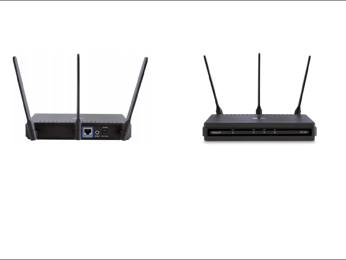
Hardware Overview
Power LED
This light will be solid green when the unit is powered on.
5GHz LED
This light will be ickering green when the 5GHz frequency is in use.
2.4GHz LED
This light will be ickering green when the 2.4GHz frequency is in use.
LAN LED
This light will be ickering green when there is active LAN trac.
Power Receptacle
The supplied power adapter connects here.
Reset Button
A pinhole button located beside the Ethernet socket is used to reset the
system or restore the factory default settings.
Note: After resetting the unit, you will still be able to access the data
on your hard drives.
LAN (PoE) Port
An Ethernet port that connects the unit to a network. This port can also
be used to supply power to this unit using Power over Ethernet.
12D-Link DAP-2553 User Manual
Section 2 - Installation
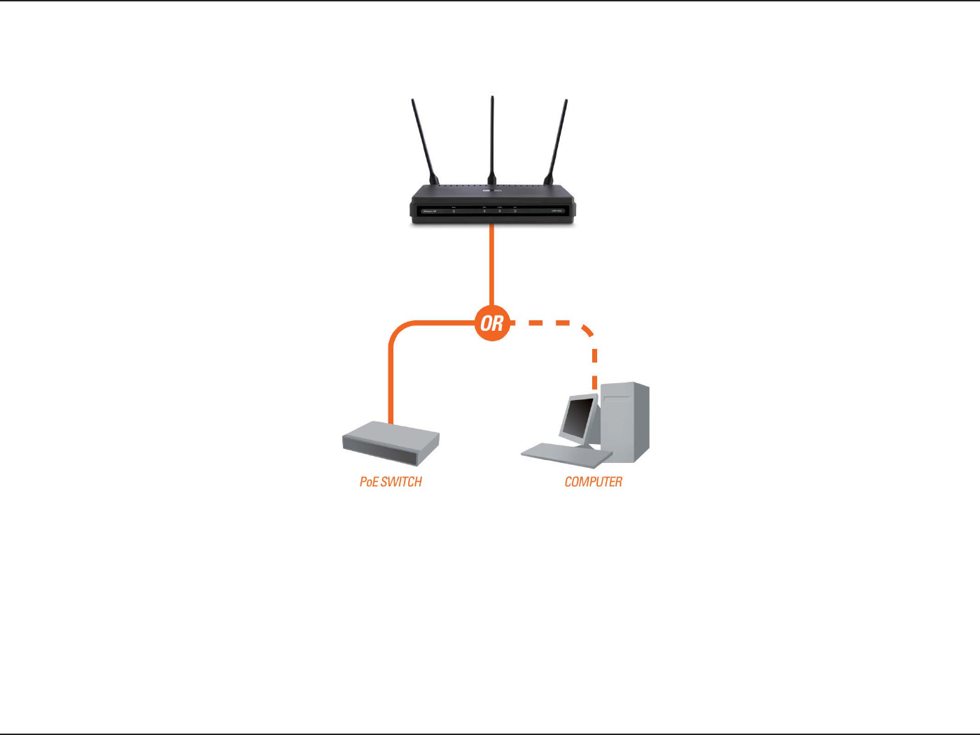
Connect Power over Ethernet (PoE)
Connect one end of an Ethernet cable (included with your access point) to the LAN port on the DAP-2553 and the other end of the Ethernet cable
to either your computer or to your PoE switch. The AP can be powered on by a PoE switch or by the power adapter shipped with the AP.
13D-Link DAP-2553 User Manual
Section 2 - Installation
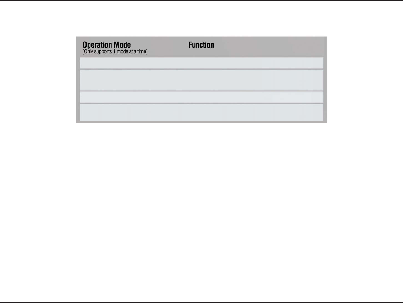
Wireless Client AP acts as a wireless network adapter for your Ethernet-
enabled device
Access Point (AP) Create a wireless LAN
WDS with AP Wirelessly connect multiple networks while still
functioning as a wireless AP
WDS Wirelessly connect multiple networks
Four Operational Modes
14D-Link DAP-2553 User Manual
Section 2 - Installation
Getting Started
1. You will need broadband Internet access.
2. Consult with your cable or DSL provider for proper installation of the modem.
3. Connect the cable or DSL modem to a router. See the printed Install Guide included with your router.
4. If you are connecting a desktop computer to your network, install a wireless PCI adapter into an available PCI
slot on your desktop computer.
5. Install the drivers for your wireless CardBus adapter into a laptop computer.
15D-Link DAP-2553 User Manual
Section 3 - Conguration
Conguration
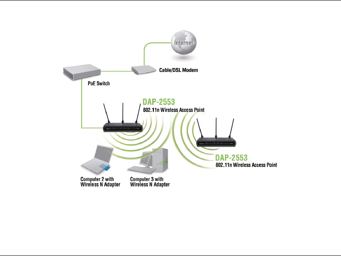
To congure the DAP-2553, use a computer that is connected to the DAP-2553 with an Ethernet cable (see the
Network Layout
diagram
).
First, disable the Access the Internet using a proxy server function. To disable this function, go to Control Panel > Internet
Options > Connections > LAN Settings and uncheck the enable box.
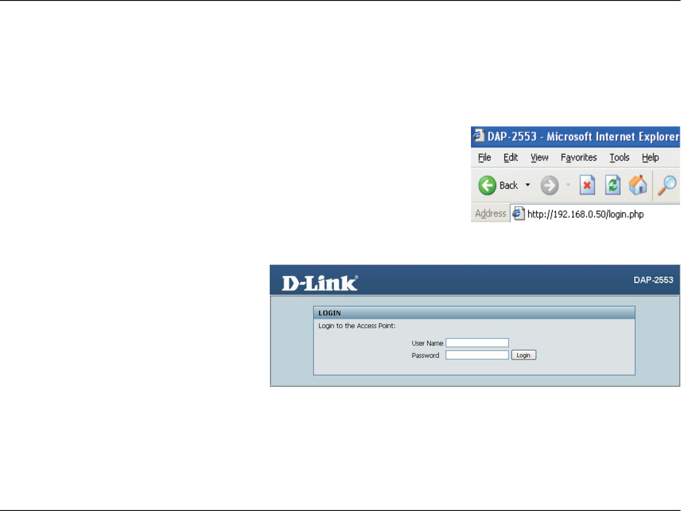
Launch your web browser.
Type the IP address and http port of the DAP-2553 in the address field
(http://192.168.0.50) and press Enter. Make sure that the IP addresses of the DAP-
2553 and your computer are in the same subnet.
Note: If you have changed the default IP address assigned to the DAP-2553, make sure to
enter the correct IP address.
Enter the user name (admin) and your password.
Leave the password eld blank by default, and
click Login.
Note: If you have changed the password, make sure to enter the correct password.
16D-Link DAP-2553 User Manual
Section 3 - Conguration
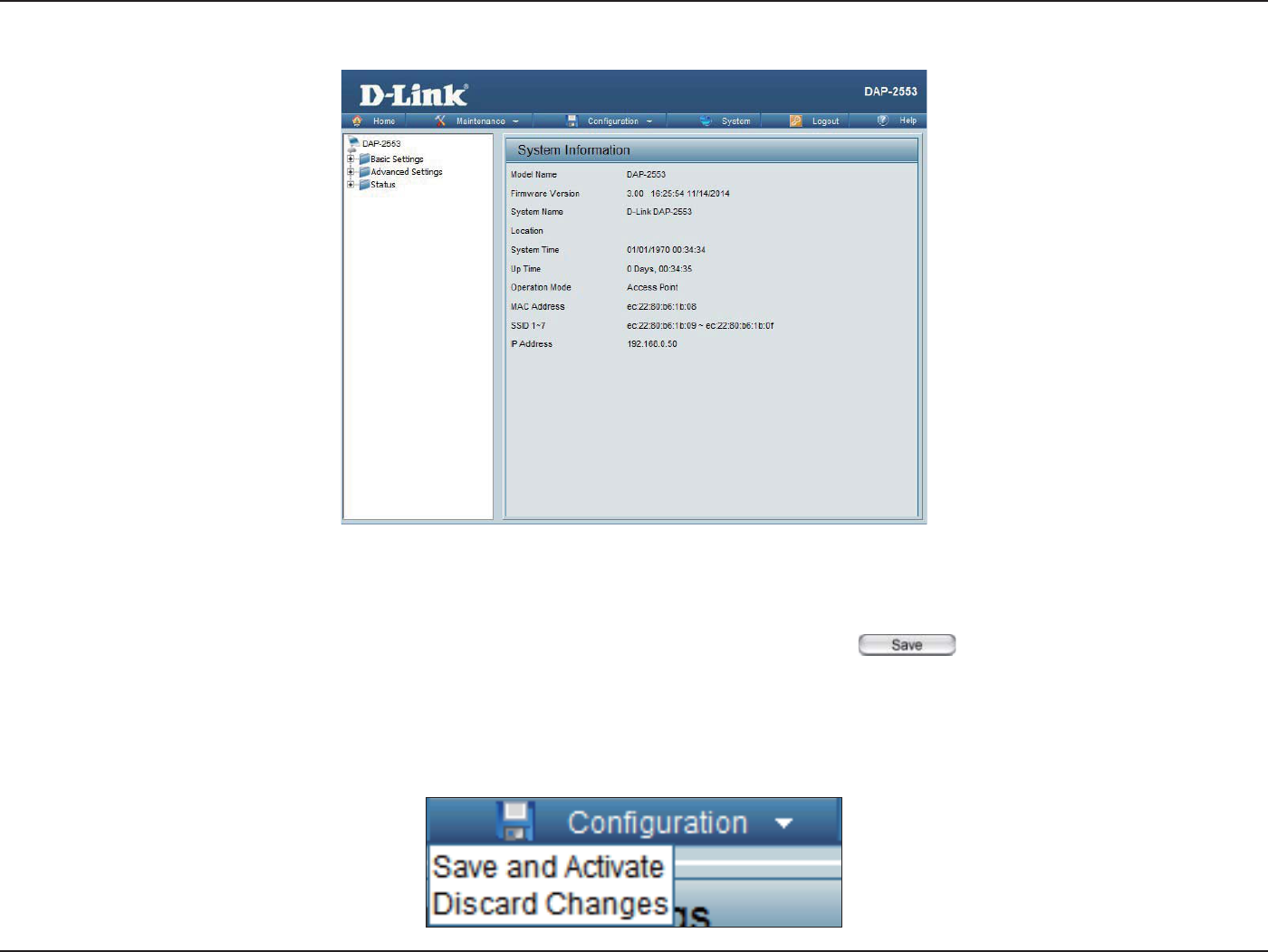
After successfully logging into the DAP-2553, the following screen will appear:
When making changes on most of the conguration screens in this section, use the button at the bottom of each
screen to save (not activate) your conguration changes.
You may change settings to multiple pages before activating. Once you are nished, click the Conguration button located
at the top of the page and then click Save and Activate.
Save and Activate Settings
17D-Link DAP-2553 User Manual
Section 3 - Conguration
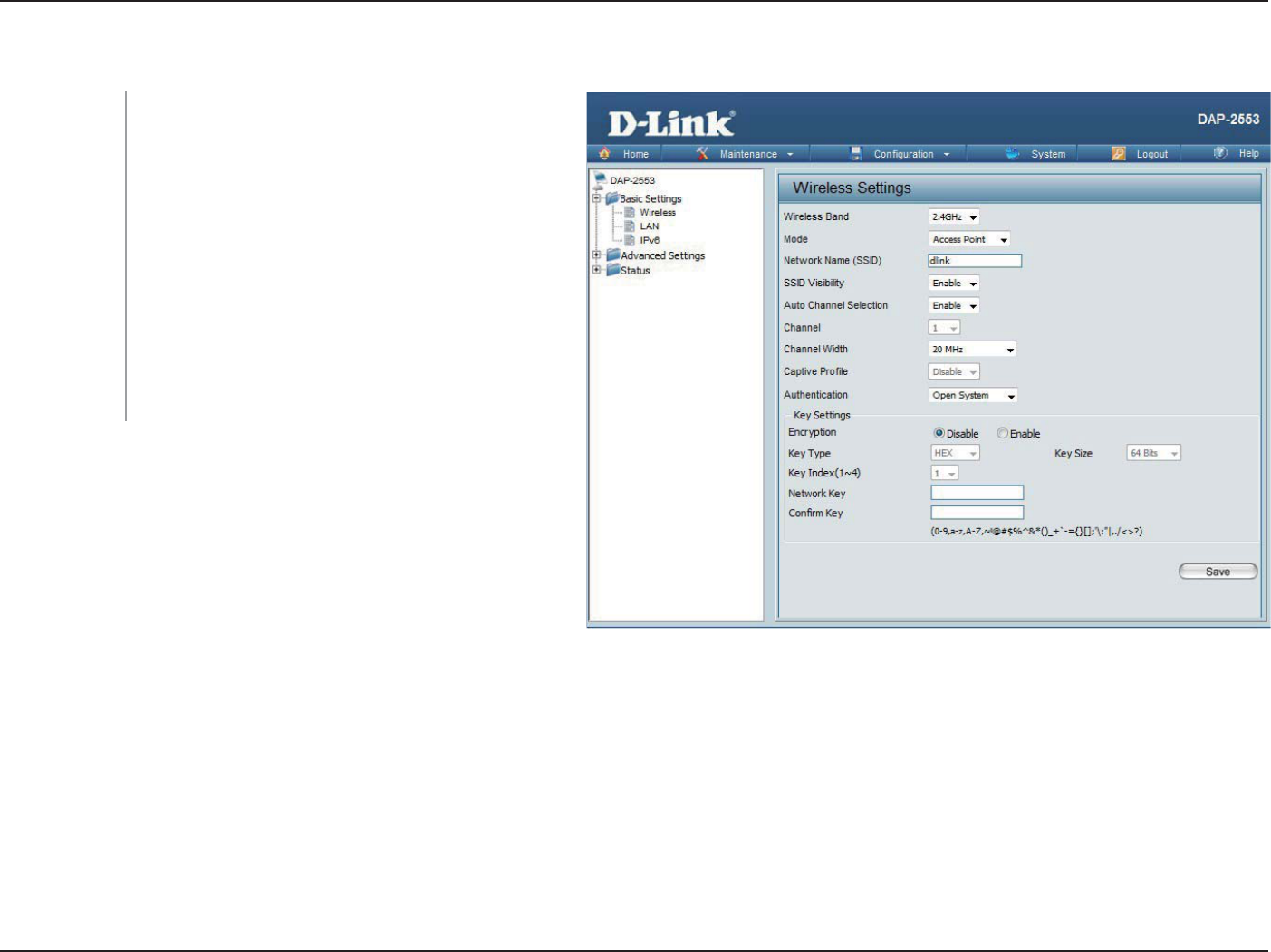
Basic Settings
Wireless
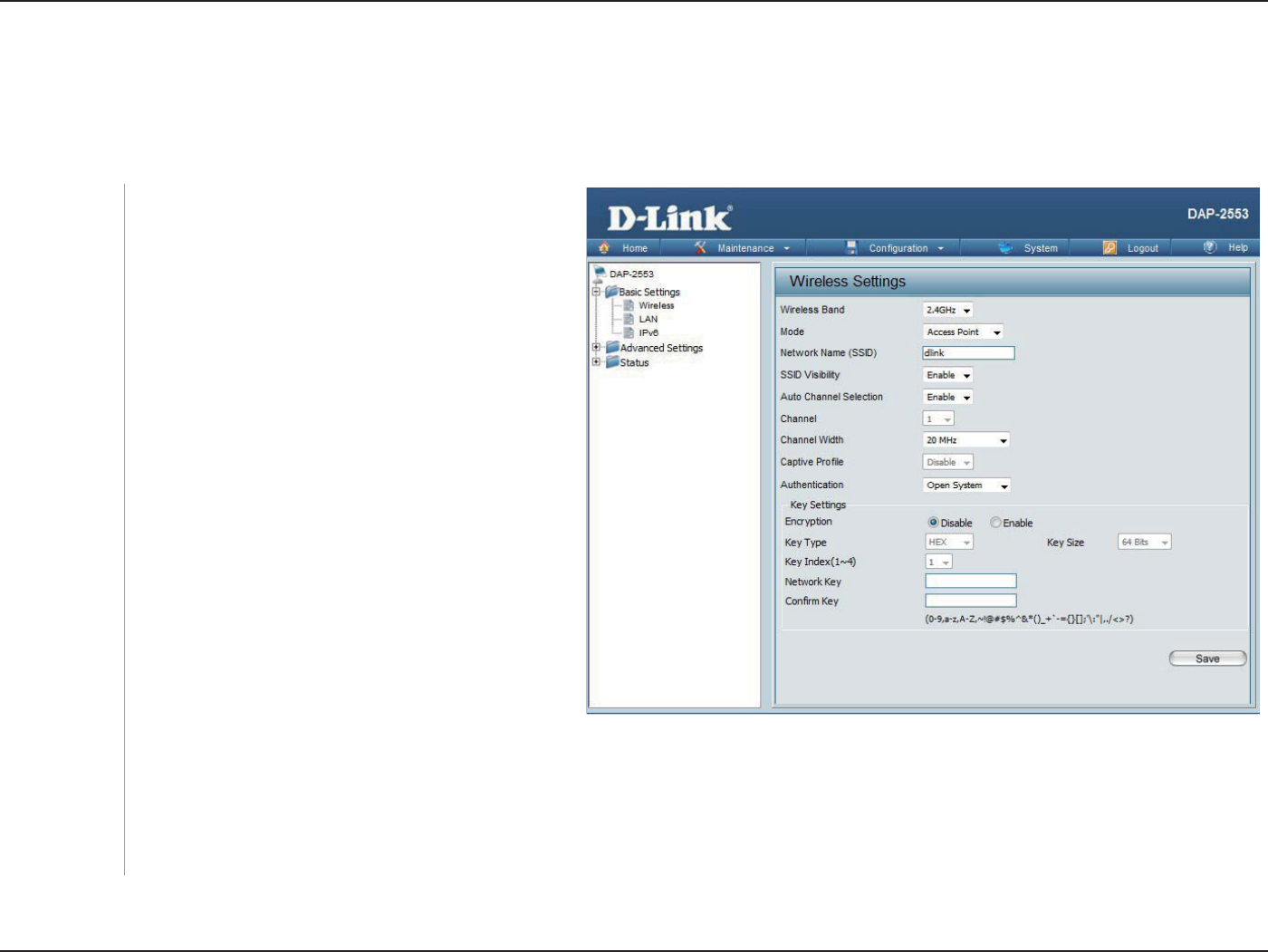
Access Point mode
Select Access Point from the drop-down menu.
The other three choices are WDS with AP, WDS,
and Wireless Client.
Service Set Identier (SSID) is the name designated
for a specic wireless local area network (WLAN).
The SSID’s factory default setting is dlink. The SSID
can be easily changed to connect to an existing
wireless network or to establish a new wireless
network. The SSID can be up to 32 characters and
is case-sensitive.
Enable or Disable SSID visibility. Enabling this
feature broadcasts the SSID across the network,
thus making it visible to all network users.
Enabling this feature automatically selects
the channel that provides the best wireless
performance. Enable is set by default. The channel
selection process only occurs when the AP is booting up.
All devices on the network must share the same channel. To change the channel, rst toggle the Auto Channel Selection setting to
Disable, and then use the drop-down menu to make the desired selection.
Note: The wireless adapters will automatically scan and match the wireless settings.
Mode:
Network Name
(SSID):
SSID Visibility:
Auto Channel
Selection:
Channel:
Wireless Band: Select either 2.4GHz or 5GHz from the
drop-down menu.

18D-Link DAP-2553 User Manual
Section 3 - Conguration
Channel Width:
Captive Prole:
Authentication:
Allows you to select the channel width you would like to operate in. Select 20 MHz if you are not using any 802.11n wireless clients.
Auto 20/40 MHz allows you to connect to both 802.11n and 802.11b/g or 802.11a wireless devices on your network.
Enable or disable captive port prole for user authentication.
Use the drop-down menu to choose Open System, Shared Key, WPA-Personal, WPA-Enterprise, or 802.11x.
Select Open System to communicate the key across the network.
Select Shared Key to limit communication to only those devices that share the same WEP settings. If multi-SSID is enabled, this
option is not available.
Select WPA-Personal to secure your network using a password and dynamic key changes. No RADIUS server is required.
Select WPA-Enterprise to secure your network with the inclusion of a RADIUS server.
Select 802.11x to secure your network using 802.11x authentication.
19D-Link DAP-2553 User Manual
Section 3 - Conguration
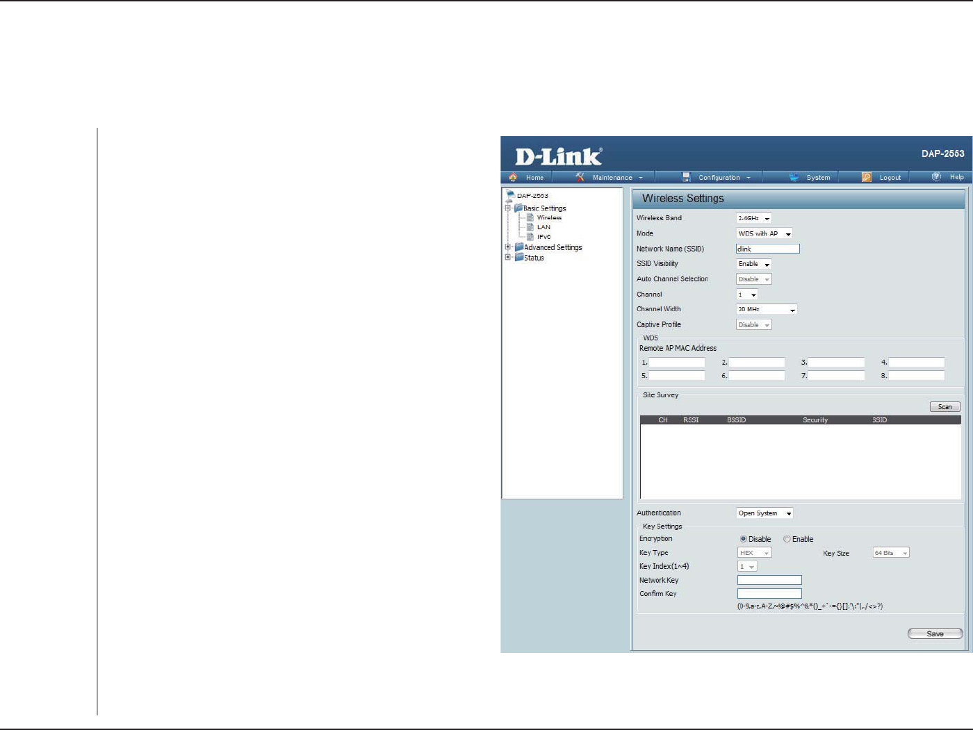
WDS with AP mode
WDS with AP mode is selected from the drop-down
menu.
Service Set Identier (SSID) is the name designated for
a specic wireless local area network (WLAN). The SSID’s
factory default setting is dlink. The SSID can be easily
changed to connect to an existing wireless network or to
establish a new wireless network.
Enable or Disable SSID visibility. Enabling this feature
broadcasts the SSID across the network, thus making it
visible to all network users.
Enabling this feature automatically selects the channel
that will provide the best wireless performance. This
feature is not supported in WDS with AP mode. The
channel selection process only occurs when the AP is
booting up.
All devices on the network must share the same channel.
To change the channel, use the drop-down menu to make
the desired selection. (Note: The wireless adapters will
automatically scan and match the wireless settings.)
Allows you to select the channel width you would like to operate in. Select 20 MHz if you are not using any 802.11n wireless clients.
Auto 20/40 MHz allows you to connect to both 802.11n and 802.11b/g or 802.11a wireless devices on your network.
Enter the MAC addresses of the APs on your network that will serve as bridges to wirelessly connect multiple networks.
Mode:
Network Name
(SSID):
SSID Visibility:
Auto Channel
Selection:
Channel:
Channel Width:
Wireless Band:
In WDS with AP mode, the DAP-2553 wirelessly connects multiple networks while still functioning as a wireless AP.
Select either 2.4GHz or 5GHz from the drop-down menu.

20D-Link DAP-2553 User Manual
Section 3 - Conguration
Enable or disable captive port prole for user authentication.
Click on the Scan button to search for available wireless networks, then click on the available network that you want to connect with.
Use the drop-down menu to choose Open System, Shared Key, or WPA-Personal.
Select Open System to communicate the key across the network.
Select Shared Key to limit communication to only those devices that share the same WEP settings. If multi-SSID is enabled, this
option is not available.
Select WPA-Personal to secure your network using a password and dynamic key changes. No RADIUS server is required.
Captive Prole:
Remote AP MAC
Address:
Site Survey:
Authentication:
21D-Link DAP-2553 User Manual
Section 3 - Conguration
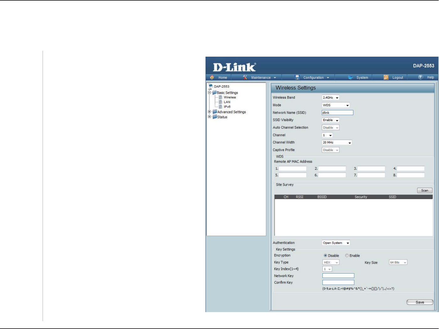
WDS mode
In WDS mode, the DAP-2553 wirelessly connects multiple networks, without functioning as a wireless AP.
WDS is selected from the drop-down menu.
Service Set Identier (SSID) is the name designated
for a specic wireless local area network (WLAN).
The SSID’s factory default setting is dlink. The SSID
can be easily changed to connect to an existing
wireless network or to establish a new wireless
network.
Enable or Disable SSID visibility. Enabling this
feature broadcasts the SSID across the network,
thus making it visible to all network users.
Enabling this feature automatically selects the
channel that will provide the best wireless
performance. This feature is not supported in WDS
mode.
All devices on the network must share the
same channel. To change the channel, use the
drop-down menu to make the desired selection.
Use the drop-down menu to choose 20 MHz or
Auto 20/40 MHz.
Disable in WDS mode.
Mode:
Network Name
(SSID):
SSID Visibility:
Auto Channel
Selection:
Channel:
Channel Width:
Captive Prole:
Wireless Band: Select either 2.4GHz or 5GHz from the
drop-down menu.

22D-Link DAP-2553 User Manual
Section 3 - Conguration
Enter the MAC addresses of the APs on your network that will serve as bridges to wirelessly connect multiple networks.
Click on the Scan button to search for available wireless networks, then click on the available network that you want to connect with.
Use the drop-down menu to choose Open System, Shared Key, or WPA-Personal.
Select Open System to communicate the key across the network.
Select Shared Key to limit communication to only those devices that share the same WEP settings.
Select WPA-Personal to secure your network using a password and dynamic key changes. No RADIUS server is required.
Remote AP
MAC Address:
Site Survey:
Authentication:
23D-Link DAP-2553 User Manual
Section 3 - Conguration
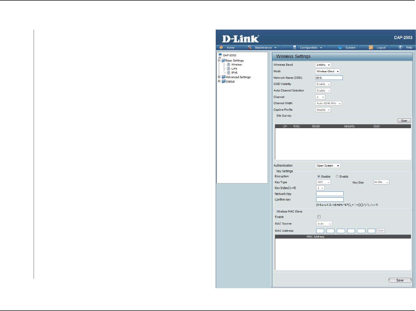
Wireless Client mode
Mode:
Network Name
(SSID):
SSID Visibility:
Auto Channel
Selection:
Channel:
Channel Width:
Captive Prole:
Site Survey:
Authentication:
Enable:
MAC Source:
MAC Address:
Wireless Band: Select either 2.4GHz or 5GHz from the drop-down menu.
Wireless Client is selected from the drop-down menu.
Service Set Identier (SSID) is the name designated for a specic wireless
local area network (WLAN). The SSID’s factory default setting is dlink. The
SSID can be easily changed to connect to an existing wireless network.
This option is unavailable in Wireless Client mode.
Enabling this feature automatically selects the channel that will provide
the best wireless performance. This feature is not supported in Wireless
Client mode.
The channel used will be displayed, and matches the AP that the DAP-
2553 is connected to when set to Wireless Client mode.
Use the drop-down menu to choose 20 MHz or Auto 20/40 MHz.
Disable in Wireless Client mode.
Click on the Scan button to search for available wireless networks, then
click on the available network that you want to connect with.
Use the drop-down menu to choose Open System or
WPA-Personal.
Select Open System to communicate the key across the network.
Select WPA-Personal to secure your network using a password and
dynamic key changes. No RADIUS server is required.
Check to enable clone MAC. This feature will allow you to change the MAC
address of the access point to the MAC address of a client.
Select the MAC source from the drop-down menu.
Enter the MAC address that you would like to assign to the access point.
24D-Link DAP-2553 User Manual
Section 3 - Conguration
Open System/Shared Key Authentication
Encryption:
Key Type*:
Key Size:
Key Index (1-4):
Key:
Use the radio button to disable or enable
encryption.
Select HEX or ASCII.
Select 64 Bits or 128 Bits.
Select the 1st through the 4th key to be the active
key.
Input up to four keys for encryption. You will
select one of these keys in the Key Index drop-
down menu.
**Hexadecimal (HEX) digits consist of the numbers 0-9 and the letters A-F.
*ASCII (American Standard Code for Information Interchange) is a code that represents English letters using numbers ranging from 0-127.
25D-Link DAP-2553 User Manual
Section 3 - Conguration
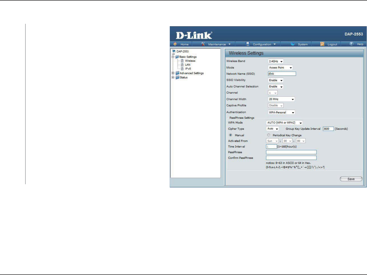
WPA/WPA2-Personal Authentication
When WPA-Personal is selected for Authentication
type, you must also select a WPA mode from the drop-
down menu: AUTO (WPA or WPA2), WPA2 Only, or
WPA Only. WPA and WPA2 use dierent algorithms.
AUTO (WPA or WPA2) allows you to use both WPA
and WPA2.
When you select WPA-Personal, you must also select
AUTO, AES, or TKIP from the drop-down menu.
Select the interval during which the group key will
be valid. The default value of 1800 is recommended.
Select Manual to enter your key (PassPhrase).
You can select Periodical Key Change to have the
access point automatically change your PassPhrase.
Enter the Activate From time and the time in hours to
change the key.
When you select WPA-Personal, please enter a
PassPhrase in the corresponding eld.
WPA Mode:
Cipher Type:
Group Key
Update:
Periodical
Key Change:
PassPhrase:
26D-Link DAP-2553 User Manual
Section 3 - Conguration
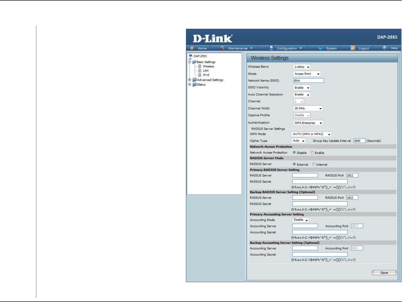
WPA/WPA2-Enterprise Authentication
When WPA-Enterprise is selected, you must also
select a WPA mode from the drop-down menu:
AUTO (WPA or WPA2), WPA2 Only, or WPA Only.
WPA and WPA2 use dierent algorithms. AUTO
(WPA or WPA2) allows you to use both WPA and
WPA2.
When WPA-Enterprise is selected, you must also
select a cipher type from the drop-down menu:
Auto, AES, or TKIP.
Select the interval during which the group key will
be valid. The recommended value is 1800. A lower
interval may reduce data transfer rates.
Enable or disable Microsoft Network Access
Protection.
Enter the IP address of the RADIUS server. Click
External if the RADIUS server is on your network
or Internal if you are using the RADIUS server on
the DAP-2553.
Enter the RADIUS port.
Enter the RADIUS secret.
Select if you want to use a different server for
accounting.
Enter the IP address of the Accounting server.
Enter the Accounting port (1813 is the default).
Enter the Accounting secret.
WPA Mode:
Cipher Type:
Group Key
Update
Interval:
Network Access
Protection:
RADIUS Server:
RADIUS Port:
RADIUS Secret:
Accounting
Mode:
Accounting
Server:
Accounting
Port:
Accounting
Secret:
27D-Link DAP-2553 User Manual
Section 3 - Conguration
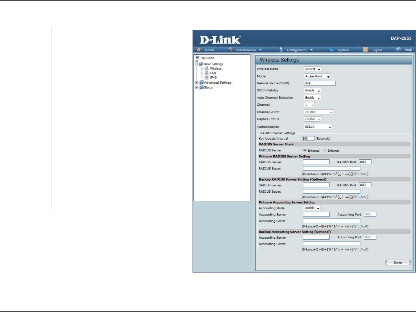
802.11x Authentication
Select the interval during which the group
key will be valid (1800 is the recommended
value). A lower interval may reduce data
transfer rates.
Enter the IP address of the RADIUS server.
Enter the RADIUS port.
Enter the RADIUS secret.
Select if you want to use a dierent server for
accounting.
Enter the IP address of the Accounting server.
Enter the Accounting port (1813 is the
default).
Enter the Accounting secret.
Key Update Interval:
RADIUS Server:
RADIUS Port:
RADIUS Secret:
Accounting Mode:
Accounting Server:
Accounting Port:
Accounting Secret:
28D-Link DAP-2553 User Manual
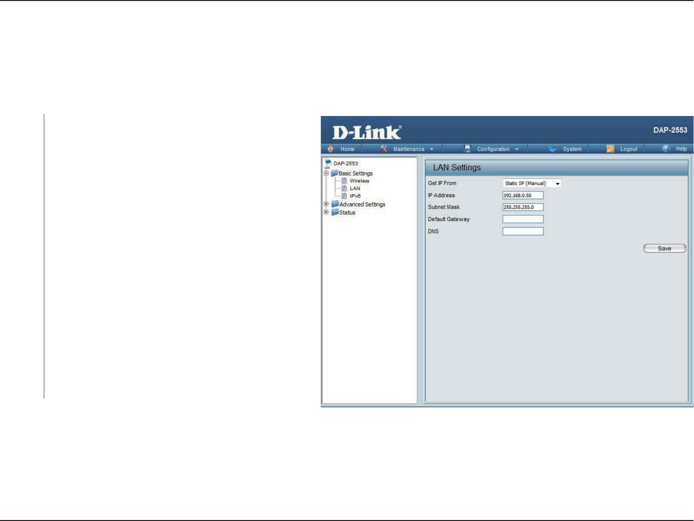
Section 3 - Conguration
Static IP (Manual) is chosen here. Choose this option
if you do not have a DHCP server in your network, or
if you wish to assign a static IP address to the DAP-
2553. When Dynamic IP (DHCP) is selected, the other
elds here will be grayed out. Please allow about two
minutes for the DHCP client to be functional once this
selection is made.
The default IP address is 192.168.0.50. Assign a static
IP address that is within the IP address range of your
network.
Enter the subnet mask. All devices in the network must
share the same subnet mask.
Enter the IP address of the gateway in your network. If
there is a gateway in your network, please enter an IP
address within the range of your network.
Enter a DNS server IP address of your choice.
LAN
Get IP
From:
IP Address:
Subnet
Mask:
Default
Gateway:
DNS :
LAN is short for Local Area Network. This is considered your internal network. These are the IP settings of the LAN interface for
the DAP-2553. These settings may be referred to as private settings. You may change the LAN IP address if needed. The LAN IP
address is private to your internal network and cannot be seen on the Internet.
29D-Link DAP-2553 User Manual
Section 3 - Conguration
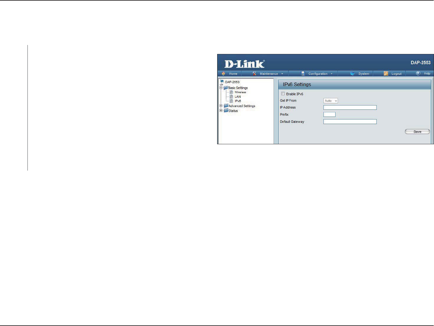
Check this box to enable IPv6.
Select either Static to enter your own IP address or Auto to
be automatically assigned by a DHCP server or IPv6 gateway.
Assign an IPv6 IP address.
The Prex is used to determine what subnet an IP address
belongs to. It must be 0~128..
Enter the default gateway address. This is usually the IP
address of your router.
IPv6
Enable
IPv6:
Get IP
From:
IP Address:
Prex:
Dafault
Gateway:
Note: If IPv6 is enabled, AP Array, QoS, and Trac Manager will all be disabled. Also, AP Client mode will change to AP mode.
The IPv6 function allows you access DAP-2553 using an IPv6 address.
30D-Link DAP-2553 User Manual
Section 3 - Conguration
Advanced Settings
Performance
*Maximum wireless signal rate derived from IEEE Standard 802.11 specications. Actual data throughput may vary. Network conditions and environmental factors, including
volume of network trac, building materials and construction, and network overhead can lower actual data throughout rate.
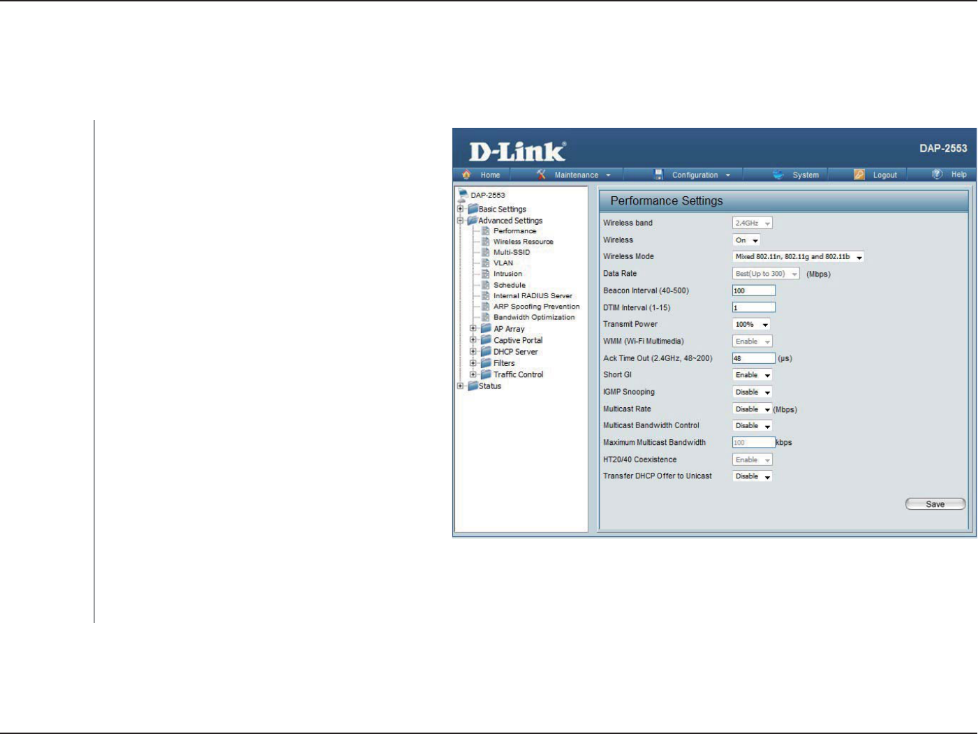
Wireless Band:
Wireless:
Wireless Mode:
Data Rate*:
Indicate 2.4GHz or 5GHz.
Use the drop-down menu to turn the wireless
function On or O.
The dierent combination of clients that can be
supported include Mixed 802.11n, 802.11g
and 802.11b, Mixed 802.11g and 802.11b and
802.11n Only in the 2.4 GHz band and Mixed
802.11n and 802.11a, 802.11a only, and
802.11n Only in the 5 GHz band. Please note
that when backwards compatibility is enabled
for legacy (802.11a/g/b) clients, degradation of
802.11n wireless performance is expected.
Indicate the base transfer rate of wireless adapters
on the wireless LAN. The AP will adjust the base
transfer rate depending on the base rate of
the connected device. If there are obstacles or
interference, the AP will step down the rate. This
option is enabled in Mixed 802.11g and 802.11b
mode (for 2.4 GHz) and 802.11a Only mode (for
5 GHz). The choices available are Best (Up to 54),
54, 48, 36, 24, 18, 12, 9, 6 for 5 GHz and Best (Up
to 54), 54, 48, 36, 24, 18, 12, 9, 6, 11, 5.5, 2 or 1
for 2.4 GHz.

31D-Link DAP-2553 User Manual
Section 3 - Conguration
Beacons are packets sent by an access point to synchronize a wireless network. Specify a value in milliseconds. The default (100)
is recommended. Setting a higher beacon interval can help to save the power of wireless clients, while setting a lower one can
help a wireless client connect to an access point faster.
Select a Delivery Trac Indication Message setting between 1 and 15. The default value is 1. DTIM is a countdown informing clients
of the next window for listening to broadcast and multicast messages.
This setting determines the power level of the wireless transmission. Transmitting power can be adjusted to eliminate overlapping
of wireless area coverage between two access points where interference is a major concern. For example, if wireless coverage is
intended for half of the area, then select 50% as the option. Use the drop-down menu to select 100%, 50%, 25%, or 12.5%.
WMM stands for Wi-Fi Multimedia. Enabling this feature will improve the user experience for audio and video applications over a
Wi-Fi network.
To eectively optimize throughput over long distance links, enter a value for Acknowledgement Time Out between 25 and 200
microseconds for 5 GHz or from 48 to 200 microseconds in the 2.4 GHz in the eld provided.
Select Enable or Disable. Enabling a short guard interval can increase throughput. However, be aware that it can also increase
the error rate in some installations due to increased sensitivity to radio-frequency installations.
Select Enable or Disable. Internet Group Management Protocol allows the AP to recognize IGMP queries and reports sent
between routers and an IGMP host (wireless STA). When IGMP snooping is enabled, the AP will forward multicast packets to an
IGMP host based on IGMP messages passing through the AP.
Adjust the multicast packet data rate here. The multicast rate is supported in AP mode, (2.4 GHZ and 5 GHZ) and WDS with AP
mode, including Multi-SSIDs.
Adjust the multicast packet data rate here. The multicast rate is supported in AP mode, and WDS with AP mode, including Multi-
SSIDs
Set the multicast packets maximum bandwidth pass through rate from the Ethernet interface to the Access Point.
Beacon Interval
(40-500):
DTM Interval
(1-15):
Transmit Power:
WMM (Wi-Fi
Multimedia):
Ack Time Out
(2.4 GHZ, 48~200)
or Ack Time Out
(5 GHZ, 25~200):
Short GI:
IGMP Snooping:
Multicast Rate:
Multicast
Bandwidth
Control :
Maximum
Multicast
Bandwidth :

32D-Link DAP-2553 User Manual
Section 3 - Conguration
Enable this option to reduce interference from other wireless networks in your area. If the channel width is operating at 40MHz
and there is another wireless network’s channel over-lapping and causing interference, the Access Point will automatically change
to 20MHz.
Enable to transfer the DHCP Oer to Unicast from LAN to WLAN, suggest to enable this function if stations number is larger than
30.
HT20/40
Coexistence :
Transfer DHCP
Oer to Unicast :
33D-Link DAP-2553 User Manual
Section 3 - Conguration
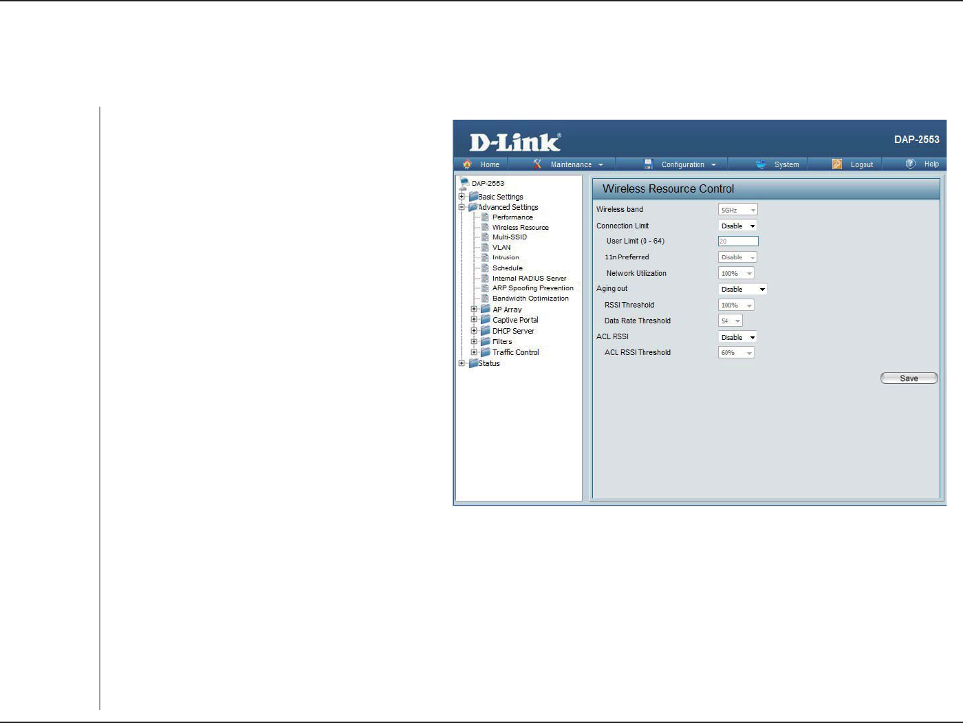
Wireless Resource Control
The Wireless Resource Control window is used to congure the wireless connection settings so that the device can detect the
better wireless connection in your environment.
Wireless band:
Connection
Limit:
User Limit:
11n Preferred:
Network Utili-
zation:
Aging out:
Select 2.4GHz in default.
Select Enable or Disable. This is an option for
load balancing. This determines whether to
limit the number of users accessing this device.
The exact number is entered in the User Limit
eld below. This feature allows the user to share
the wireless network trac and the client using
multiple APs. If this function is enabled and
when the number of users exceeds this value,
or the network utilization of this AP exceeds the
percentage that has been specied, the DAP-
2553 will not allow clients to associate with the
AP.
Set the maximum amount of users that are
allowed access (zero to 64 users) to the device
using the specied wireless band. The default
setting is 20.
Use the drop-down menu to Enable the 11n
Preferred function. The wireless clients with
802.11n protocol will have higher priority to
connect to the device.
Set the maximum utilization of this access point for service. The DAP-2553 will not allow any new clients to associate with the AP
if the utilization exceeds the value the user species. Select a utilization percentage between 100%, 80%, 60%, 40%, 20%, or 0%.
When this network utilization threshold is reached, the device will pause one minute to allow network congestion to dissipate.
Use the drop-down menu to select the criteria of disconnecting the wireless clients. Available options are RSSI and Data Rate.

34D-Link DAP-2553 User Manual
Section 3 - Conguration
RSSI Thresh-
old:
Data Rate
Threshold:
ACL RSSI:
ACL RSSI
Threshold:
When RSSI is selected in the Aging out drop-down menu, select the percentage of RSSI here. When the RSSI of wireless clients is
lower than the specied percentage, the device disconnects the wireless clients.
When Data Rate is selected in the Aging out drop-down menu, select the threshold of data rate here. When the data rate of
wireless clients is lower than the specied number, the device disconnects the wireless clients.
Use the drop-down menu to Enable the function. When enabled, the device denies the connection request from the wireless
clients with the RSSI lower than the specied threshold below.
Set the ACL RSSI Threshold.
35D-Link DAP-2553 User Manual
Section 3 - Conguration
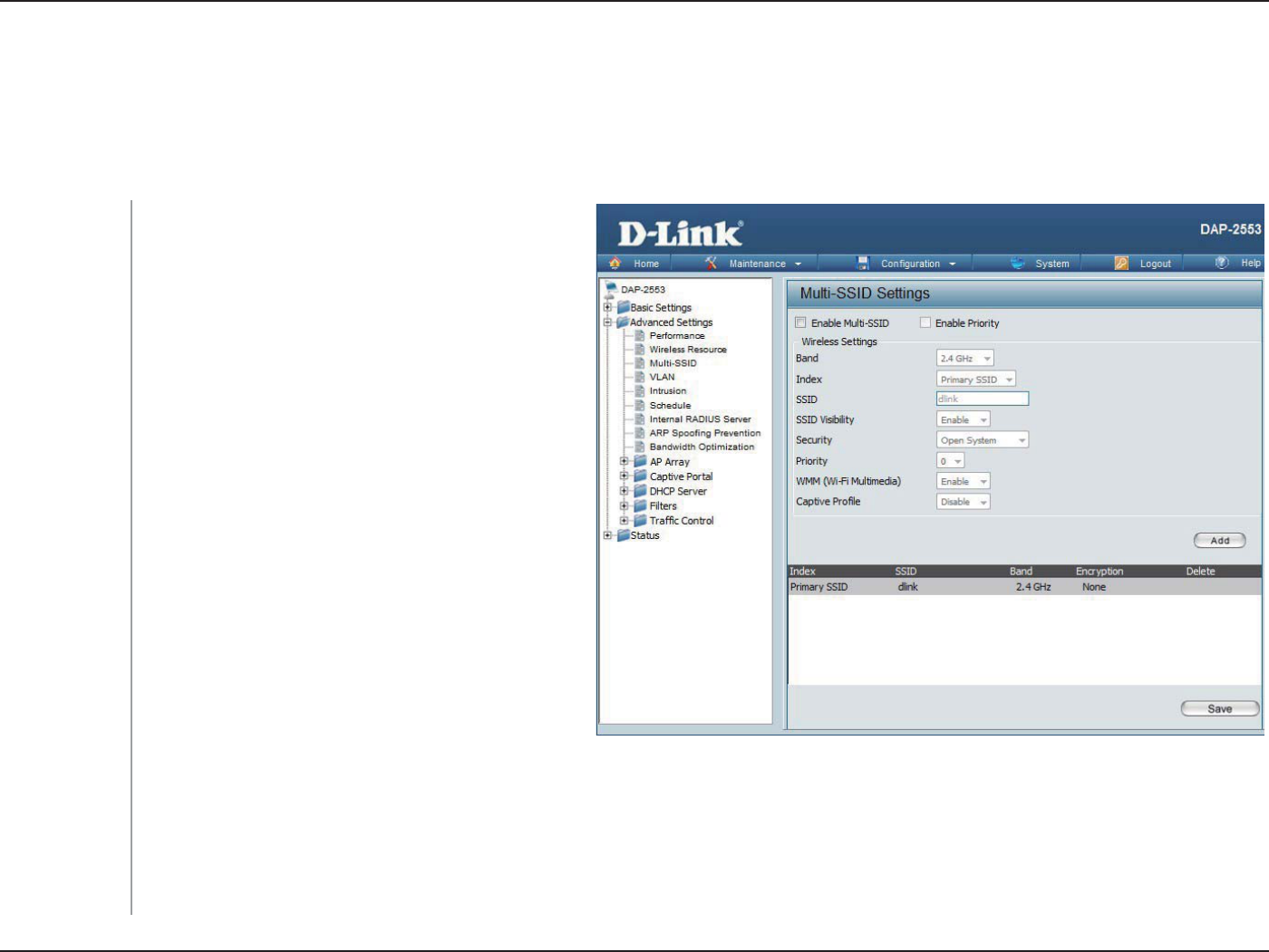
The device supports up to four multiple Service Set Identiers. In the Basic > Wireless section, you can set the Primary SSID.
The SSID’s factory default setting is dlink. The SSID can be easily changed to connect to an existing wireless network or to
establish a new wireless network.
Check to enable support for multiple SSIDs.
Check to enable the priority support for Multi-
SSID
This read-only value is the current band setting.
You can select up to three multi-SSIDs. With
the Primary SSID, you have a total of four
multi-SSIDs.
Service Set Identier (SSID) is the name designated
for a specic wireless local area network (WLAN).
The SSID’s factory default setting is dlink. The
SSID can be easily changed to connect to an
existing wireless network or to establish a new
wireless network.
Enable or Disable SSID visibility. Enabling this
feature broadcasts the SSID across the network,
thus making it visible to all network users.
The Multi-SSID security can be Open System, WPA-Personal, or WPA-Enterprise. For a detailed description of the Open System
parameters, please go to page 23. For a detailed description of the WPA-Personal parameters, please go to page 24. For a detailed
description of the WPA-Enterprise parameters, please go to page 25.
Enable
Multi-SSID:
Enable Priority :
Band:
Index:
SSID:
SSID Visibility:
Security:
Multi-SSID

36D-Link DAP-2553 User Manual
Section 3 - Conguration
Check the Enable Priority box at the top of this window to enable. Select the priority from the drop-down menu.
Select Enable or Disable.
Enable or disable captive prole for user authentication.
Priority:
WMM (Wi-Fi
Multimedia):
Captive Prole:
37D-Link DAP-2553 User Manual
Section 3 - Conguration
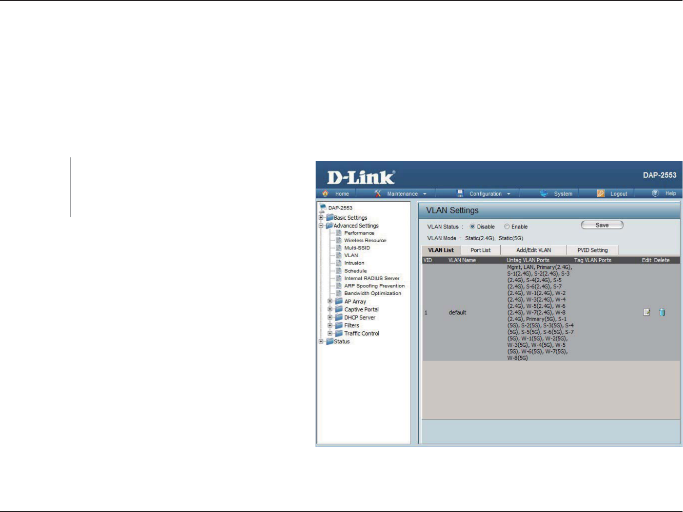
VLAN
VLAN List
The DAP-2553 supports VLANs. VLANs can be created with a Name and VID. Mgmt (TCP stack), LAN, Primary/
Multiple SSID, and WDS connection can be assigned to VLANs as they are physical ports. Any packet which enters the
DAP-2553 without a VLAN tag will have a VLAN tag inserted with a PVID.
The VLAN List tab displays the current VLANs.
Use the radio button to toggle between Enable
or Disable. Next, go to the Add/Edit VLAN tab
to add or modify an item on the VLAN List tab.
VLAN Status:
38D-Link DAP-2553 User Manual
Section 3 - Conguration
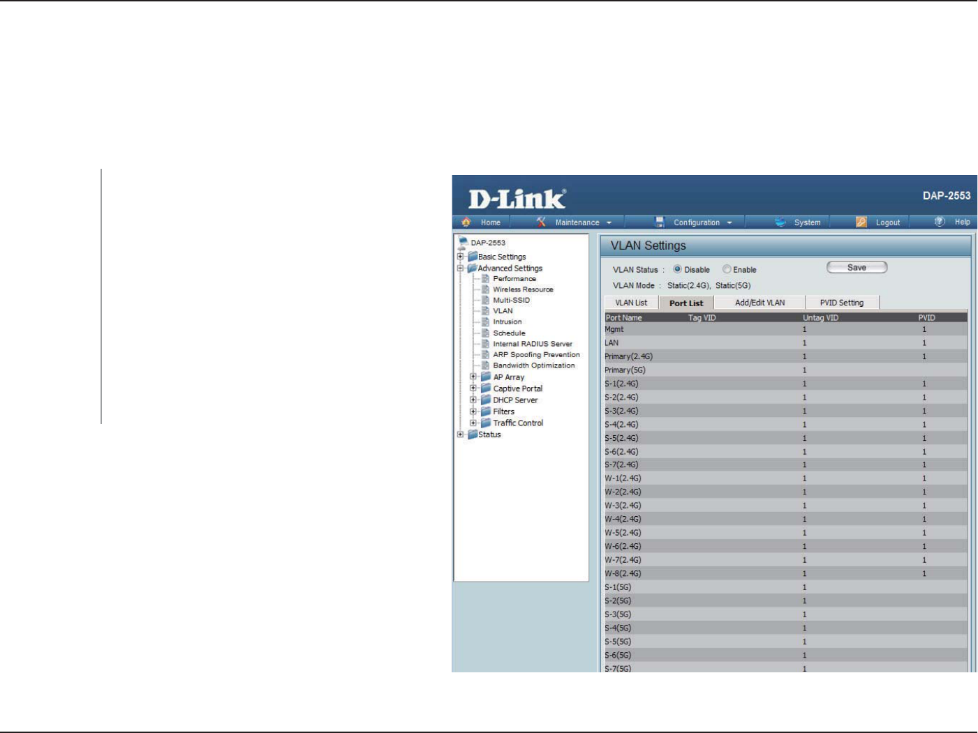
Port List
The Port List tab displays the current ports. If you want to congure the guest and internal networks on a Virtual LAN (VLAN),
the switch and DHCP server you are using must also support VLANs. As a prerequisite step, congure a port on the switch for
handling VLAN tagged packets as described in the IEEE 802.1Q standard.
Use the radio button to toggle to Enable. Next,
go to the Add/Edit VLAN tab to add or modify
an item on the VLAN List tab.
The name of the port is displayed in this column.
The Tagged VID is displayed in this column.
The Untagged VID is displayed in this column.
The Port VLAN Identifier is displayed in this
column.
VLAN Status:
Port Name:
Tag VID:
Untag VID:
PVID:
39D-Link DAP-2553 User Manual
Section 3 - Conguration
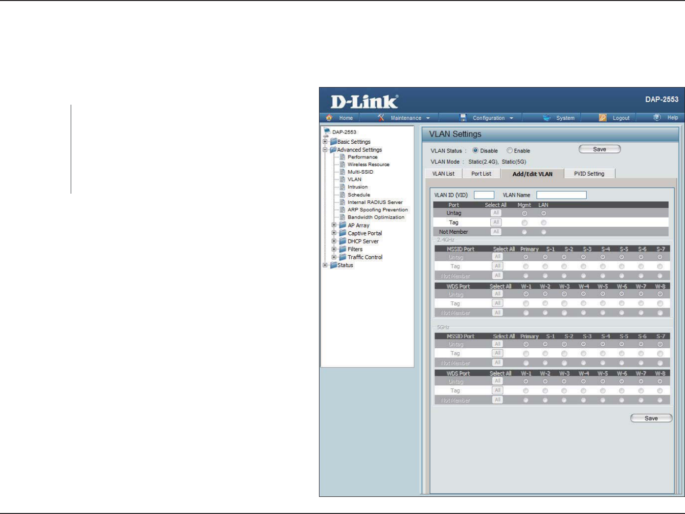
Add/Edit VLAN
The Add/Edit VLAN tab is used to congure VLANs. Once you have made the desired changes, click the Save button to let
your changes take eect.
Use the radio button to toggle to Enable.
Provide a number between 1 and 4094 for
the Internal VLAN.
Enter the VLAN to add or modify.
VLAN Status:
VLAN ID:
VLAN Name:
40D-Link DAP-2553 User Manual
Section 3 - Conguration
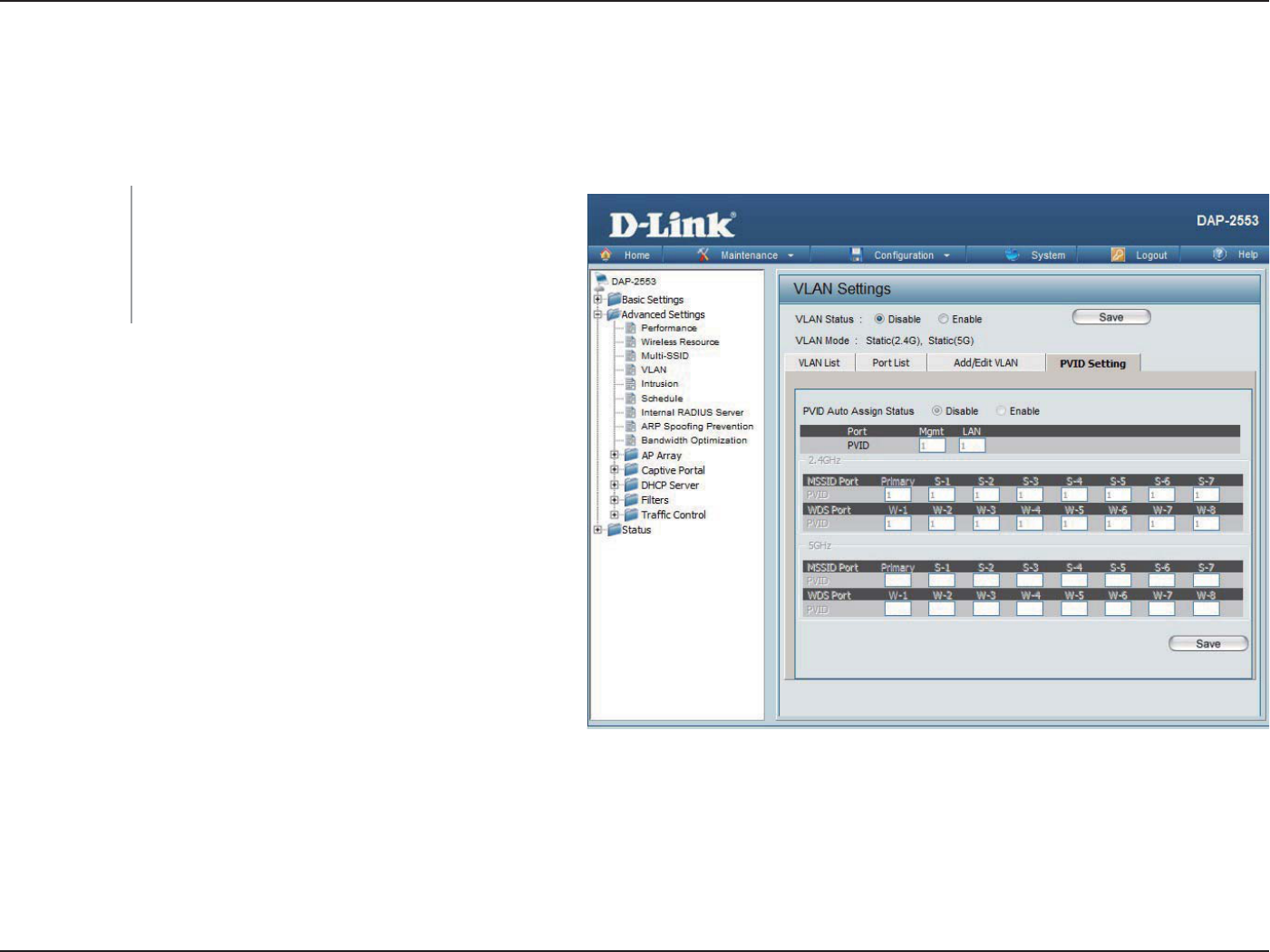
PVID Setting
The PVID Setting tab is used to enable/disable the Port VLAN Identier Auto Assign Status as well as to congure various types
of PVID settings. Click the Save button to let your changes take eect.
Use the radio button to toggle between Enable
and Disable.
Use the radio button to toggle PVID auto assign
status to Enable.
VLAN Status:
PVID Auto As-
sign Status:
41D-Link DAP-2553 User Manual
Section 3 - Conguration
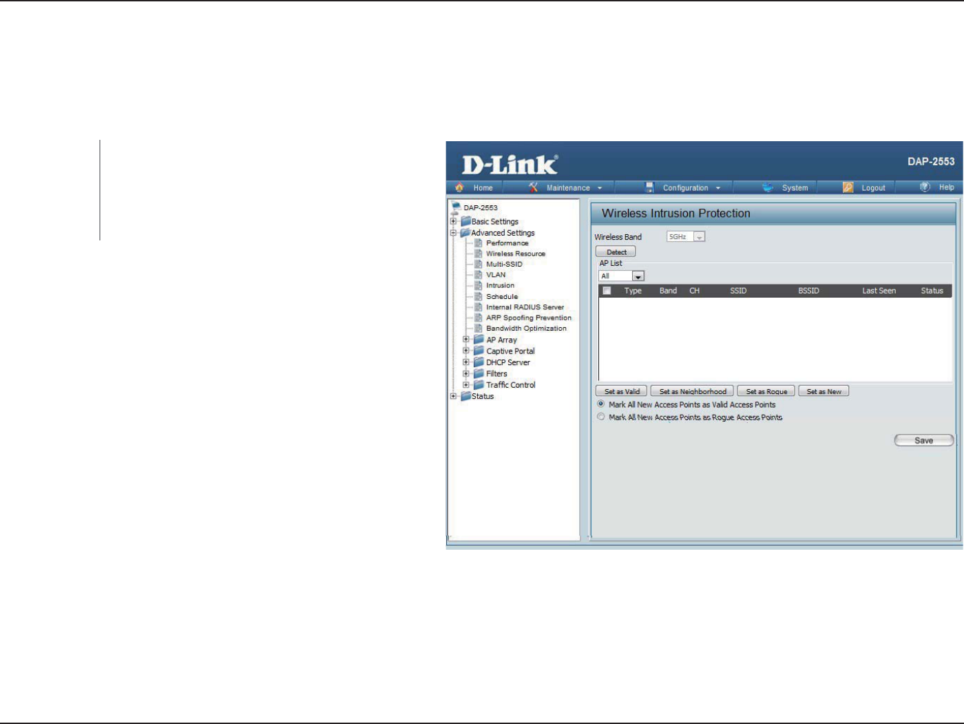
Intrusion
The Wireless Intrusion Protection window is used to set APs as All, Valid, Neighborhood, Rogue, and New. Click the Save
button to let your changes take eect.
The choices include All, Valid, Neighbor, Rogue,
and New.
Click this button to initiate a scan of the network.
AP List:
Detect:
42D-Link DAP-2553 User Manual
Section 3 - Conguration
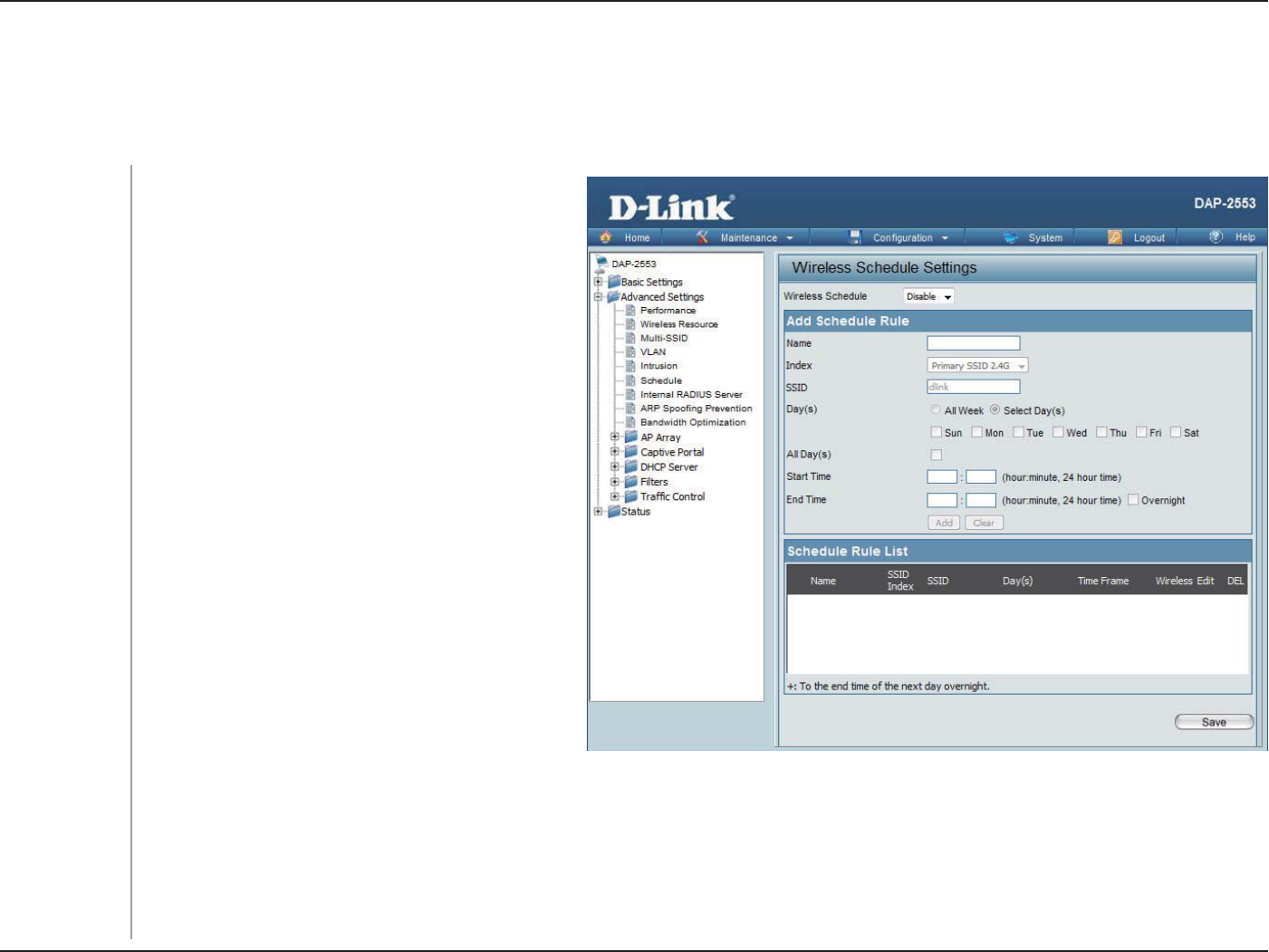
Schedule
The Wireless Schedule Settings window is used to add and modify scheduling rules on the device. Click the Save button to let
your changes take eect.
Use the drop-down menu to enable the device’s
scheduling feature.
Enter a name for the new scheduling rule in the
eld provided.
Select the index from the drop-down menu.
Enter the name of your wireless network (SSID).
Toggle the radio button between All Week and
Select Day(s). If the second option is selected,
check the specic days you want the rule to be
eective on.
Check this box to have your settings apply 24
hours a day.
Enter the start time for your rule. If you selected
All Day, this option will be greyed out.
Enter the end time for your rule.
Click to add the rule to the list.
This section will display the list of created
schedules.
Click the Save button to save your created rules.
Wireless
Schedule:
Name:
Index:
SSID:
Day(s):
All Day(s):
Start Time:
End Time:
Add:
Schedule Rule
List:
Save:
43D-Link DAP-2553 User Manual
Section 3 - Conguration
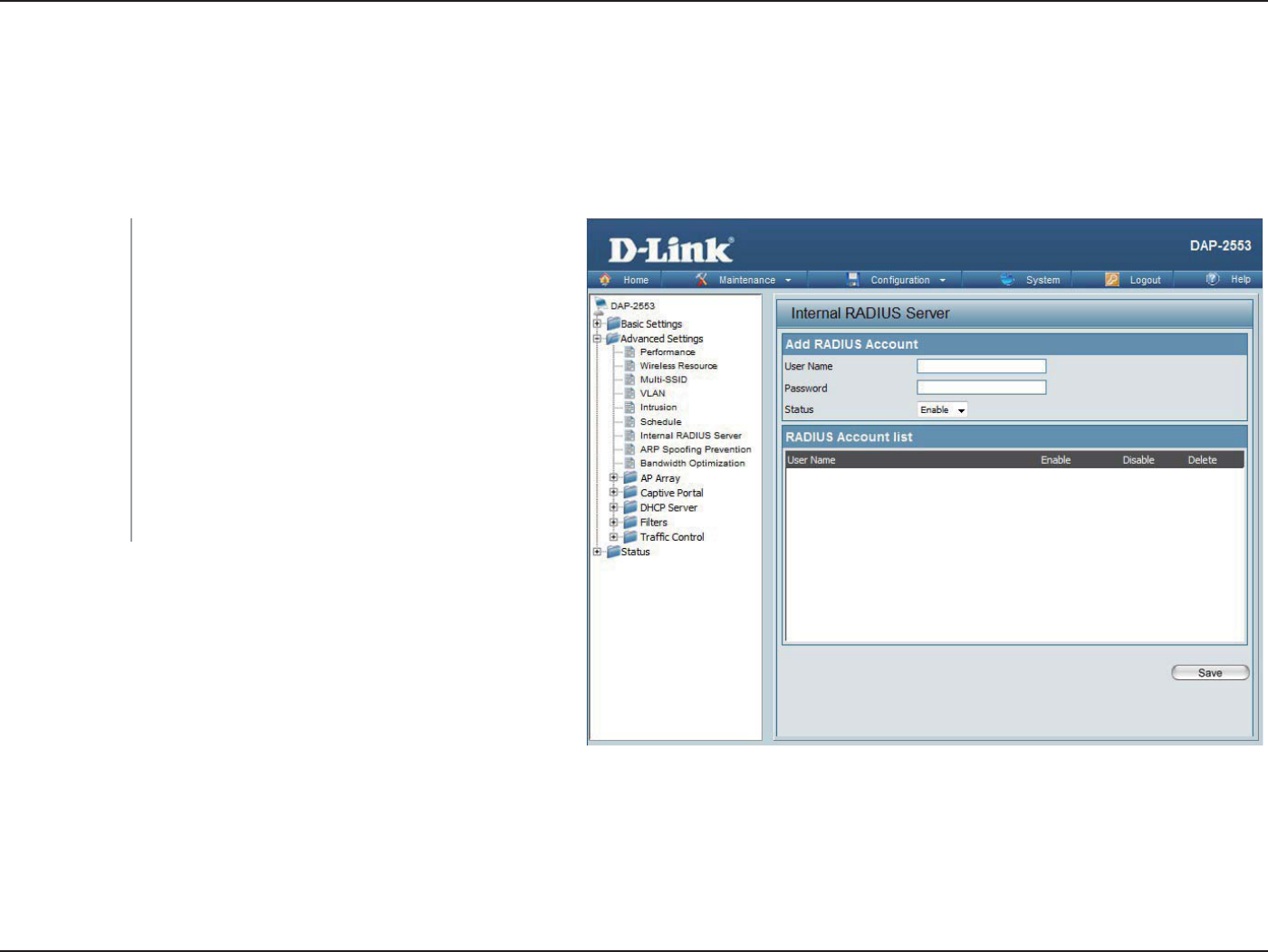
Internal RADIUS Server
The DAP-2553 features a built-in RADIUS server. Once you have nished adding a RADIUS account, click the Save button to let
your changes take eect. The newly-created account will appear in this RADIUS Account List. The radio buttons allow the user
to enable or disable the RADIUS account. Click the icon in the delete column to remove the RADIUS account. We suggest you
limit the number of accounts below 30.
User Name:
Password:
Status:
RADIUS Account
List:
Enter a name to authenticate user access to the
internal RADIUS server.
Enter a password to authenticate user access to
the internal RADIUS server. The length of your
password should be 8~64.
Toggle the drop-down menu between Enable and
Disable.
Displays the list of users.
44D-Link DAP-2553 User Manual
Section 3 - Conguration
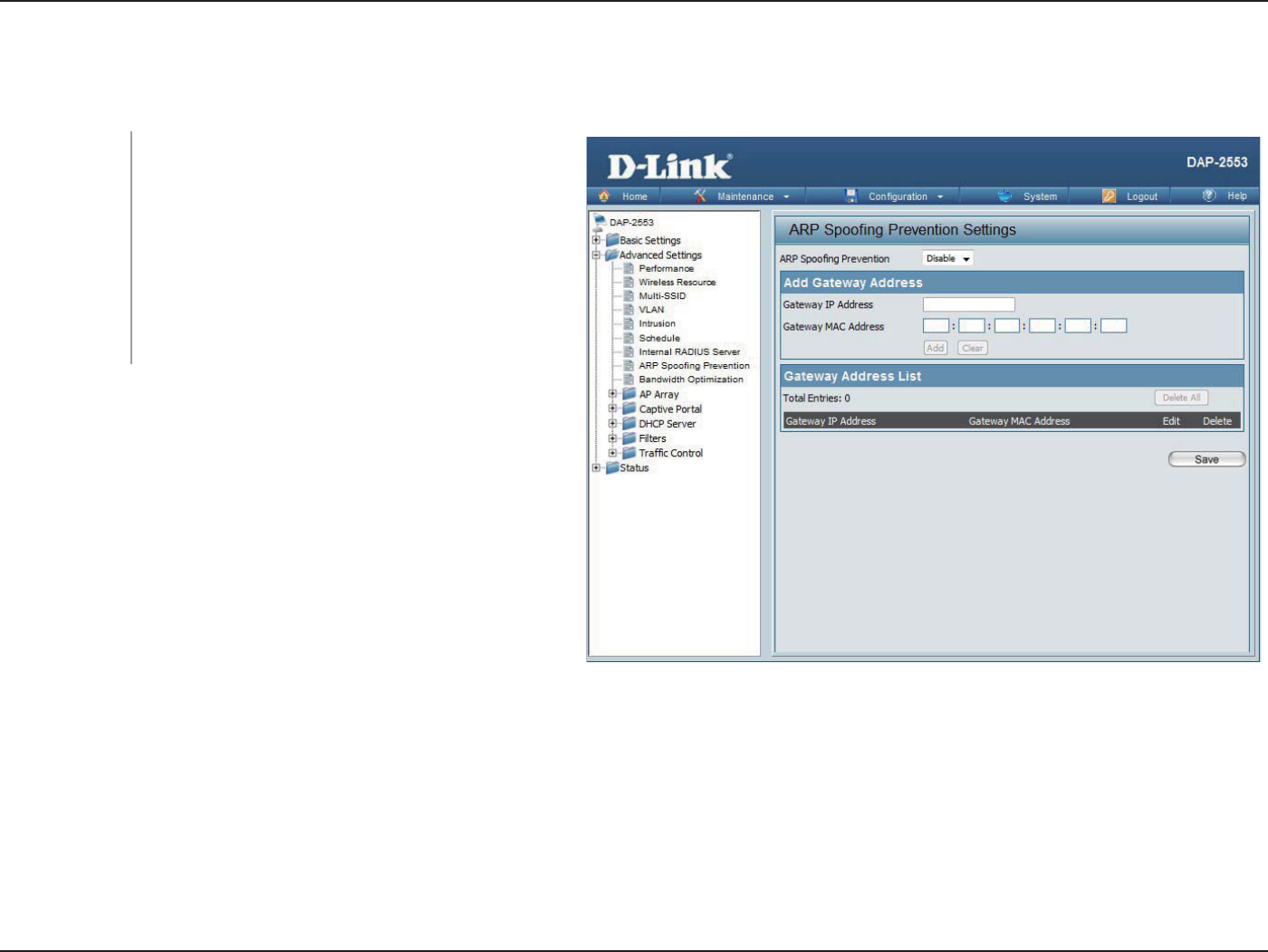
ARP Spoong Prevention
The ARP Spoong Prevention feature allows users to add IP/MAC address mapping to prevent arp spoong attack.
ARP Spoong
Prevention:
Gateway IP
Address:
Gateway MAC
Address:
This check box allows you to enable the arp
spoong prevention function.
Enter a gateway IP address.
Enter a gateway MAC address.
45D-Link DAP-2553 User Manual
Section 3 - Conguration
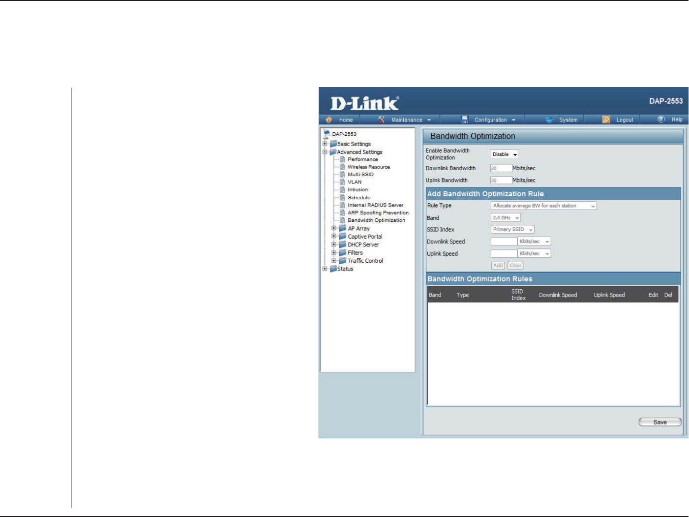
Bandwidth Optimization
The Bandwidth Optimization window allows the user to manage the bandwidth of the device and arrange the bandwidth for
various wireless clients. When the Bandwidth Optimization ruile is nished, click the Add button. To discard the Add Bandwidth
Optimization Rule settings, click the Clear button. Click the Save button to let your changes take eect.
Enable
Bandwidth
Optimization:
Downlink
Bandwidth:
Uplink
Bandwidth:
Allocate average
BW for each
station:
Allocate
maximum BW
for each station:
Allocate
dierent BW for
b/g/n stations:
Allocate specic
BW for SSID:
Rule Type:
Use the drop-down menu to Enable the Bandwidth
Optimization function.
Enter the downlink bandwidth of the device in
Mbits per second.
Enter the uplink bandwidth of the device in Mbits
per second.
AP will distribute average bandwidth for each
client.
Specify the maximum bandwidth for each
connected client. Reserve certain bandwidth for
future clients.
The weight of 11b/g/n client are 10%/20%/70% ;
20%/80%. AP will distribute dierent bandwidth
for 11b/g/n clients.
All clients share the total bandwidth.
Use the drop-down menu to select the type that is
applied to the rule. Available options are: Allocate
average BW for each station, Allocate maximum BW
for each station, Allocate dierent BW for 11 b/g/n
stations, and Allocte specic BW for SSID.

46D-Link DAP-2553 User Manual
Section 3 - Conguration
Band:
SSID Index:
Downlink Speed:
Uplink Speed:
Indicate the selected wireless band for DAP-2553.
Use the drop-down menu to select the SSID for the specied wireless band.
Enter the limitation of the downloading speed in either Kbits/sec or Mbits/sec for the rule.
Enter the limitation of the uploading speed in either Kbits/sec or Mbits/sec for the rule.
47D-Link DAP-2553 User Manual
Section 3 - Conguration
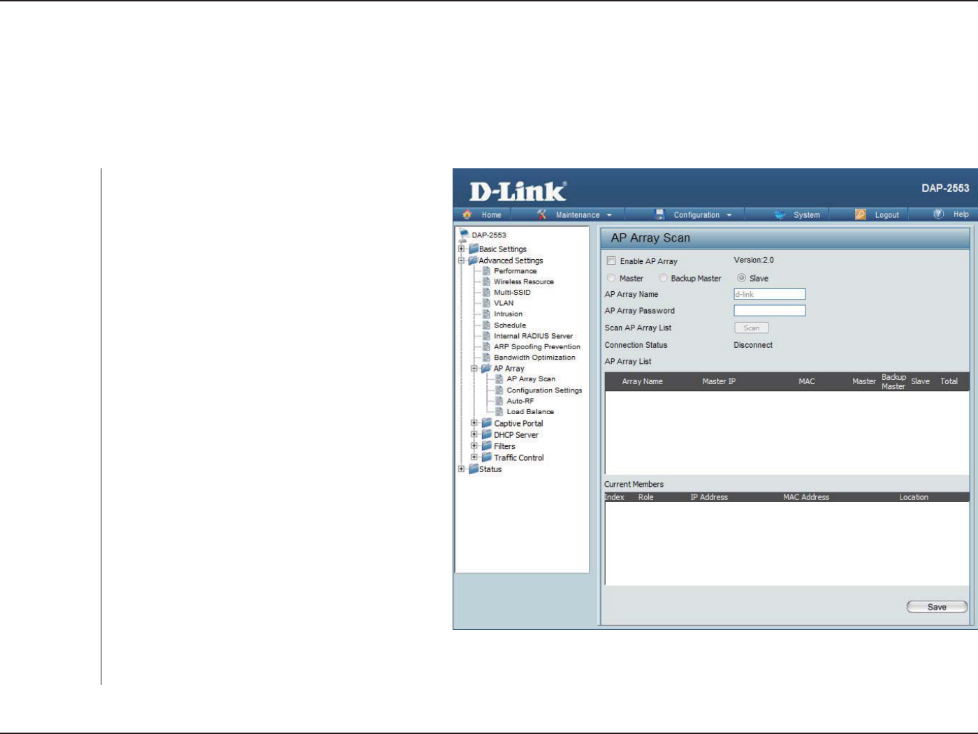
AP Array
The AP Array window is used to create up to 32 APs on a local network to be organized into a single group in order to increase
ease of management. Click the Save button to let your changes take eect. Central WiFiManager and AP Array are mutually
exclusive functions.
Enable AP Array:
AP Array Name:
AP Array
Password:
Scan AP Array
List:
Connection
Status:
AP Array List:
Current
Members:
Select the check box to enable the AP array function.
The three modes that are available are Master,
Backup Master, and Slave. APs in the same array
will use the same conguration. The conguration
will sync the Master AP to the Slave AP and the
Backup Master AP when a Slave AP and a Backup
Master AP join the AP array.
Enter an AP array name for the group here.
Enter an AP array password for the group here. This
password must be the same on all the APs in the
group.
Click this button to initiate a scan of all the available
APs currently on the network.
Display the AP array connection status.
This table displays the current AP array status for the
following parameters: Array Name, Master IP, MAC,
Master, Backup Master, Slave, and Total.
This table displays all the current array members.
The DAP-2553 AP array feature supports up to eight AP array members.
AP Array Scan
48D-Link DAP-2553 User Manual
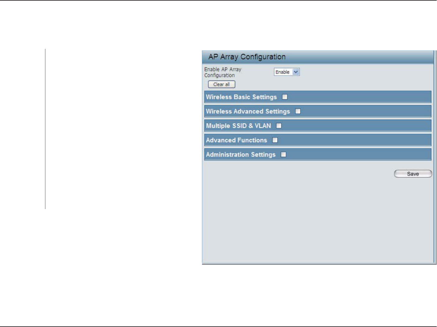
Section 3 - Conguration
In the AP array conguration settings windows, users can specify which settings all the APs in the group will inherit from the
master AP. Make the required selection in this window and click the Save button to accept the changes made.
Enable AP Array
Conguration:
Wireless Basic
Settings:
Wireless
Advanced
Settings:
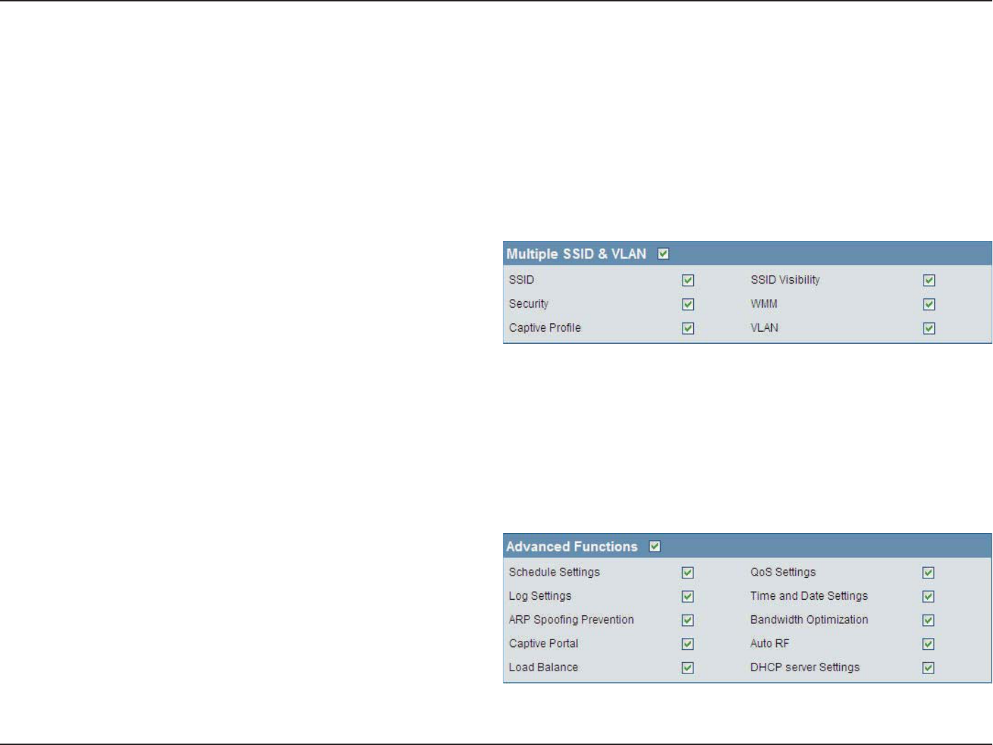
Multiple SSID &
VLAN:
Advanced
Functions:
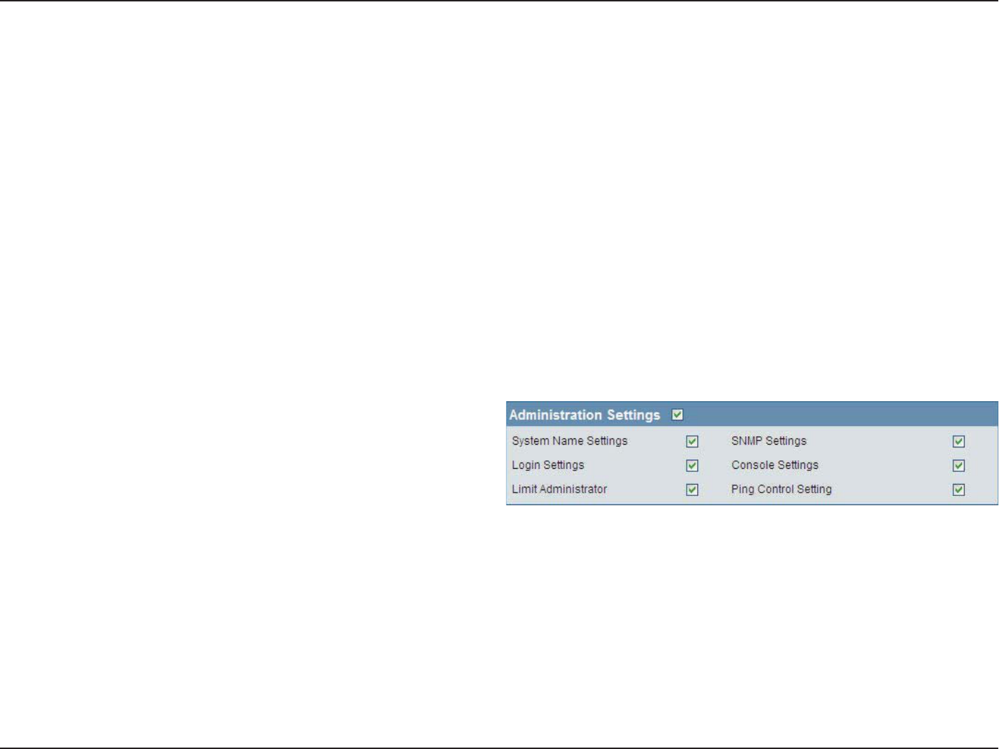
Administration
Settings:
Select to Enable or Disable the AP array congure
feature here.
Select this option to specify the basic wireless
settings that the APs in the group will inherit.
Select this option to specify the advanced wireless
settings that the APs in the group will inherit.
Select this option to specify the multiple SSIDs and
VLAN settings that the APs in the group will inherit.
Select this option to specify the other advanced
settings that the APs in the group will inherit.
Select this option to specify the administrative
settings that the APs in the group will inherit.
Conguration Settings
49D-Link DAP-2553 User Manual
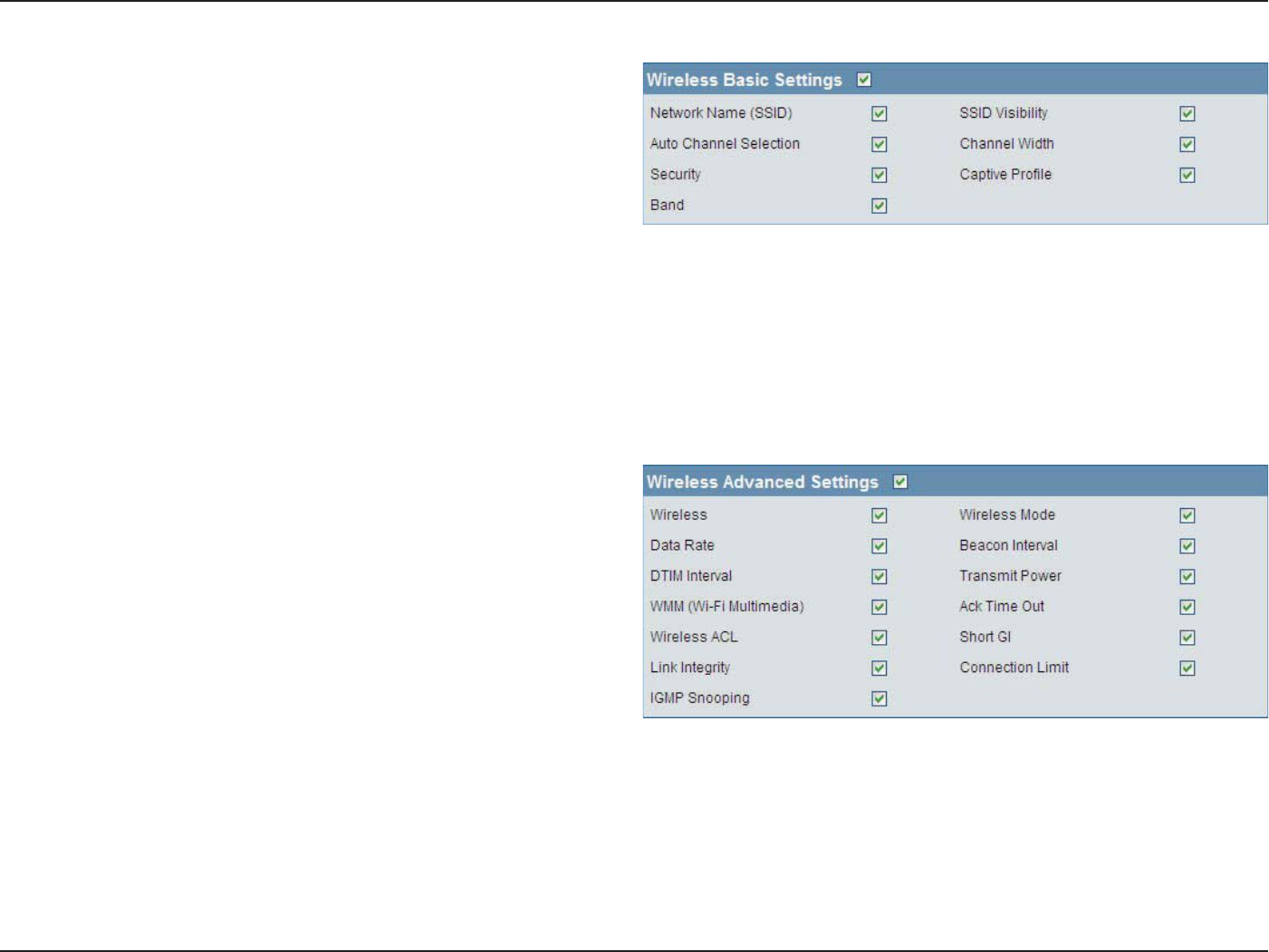
Section 3 - Conguration
Network Name (SSID):
SSID Visibility:
Auto Channel
Selection:
Channel Width:
Security:
Captive Prole:
Band:
Select this option to use the same SSID.
Select this option to enable SSID visibility.
Select this option to use auto channel selection.
Select this option to use the same channel width.
Wireless Basic Settings
Wireless:
Wireless Mode:
Data Rate:
Beacon Interval:
DTIM Interval:
Transmit Power:
WMM (Wi-Fi
Multimedia):
Ack Time Out:
Wireless ACL:
Select this option to use the same wireless
settings.
Select this option to use the same wireless mode.
Select this option to use the same data rate.
Select this option to use the same beacon interval.
Select this option to use the same DTIM interval.
Wireless Advanced Settings
Select this option to use the same wireless security.
Select this option to use the same captive prole settings.
Select this option to use the same wireless band.
Select this option to use the same transmit power.
Select this option to use the same WMM settings.
Select this option to use the same ACK timeout value.
Select this option to use the same wireless ACL settings.
50D-Link DAP-2553 User Manual
Section 3 - Conguration
SSID:
SSID Visibility:
Security:
WMM:
Captive Prole:
VLAN:
Select this option to use the same multi-SSIDs.
Select this option to use the same SSID visible.
Select this option to use the same wireless security
settings.
Multiple SSID & VLAN
Short GI:
Link Integrity:
Connection Limit:
IGMP Snooping::
Select this option to use the same short GI settings.
Select this option to use the same link integrity settings.
Select this option to use the same connection limit value.
Select this option to use the same IGMP snooping settings.
Schedule Settings:
QoS Settings:
Log Settings:
Time and Date
Settings:
Select this option to use the same schedule
settings.
Select this option to use the same Quality of
Service settings.
Select this option to use the same log settings.
Select this option to use the same time and date
settings.
Advanced Functions
Select this option to use the same WMM settings.
Select this option to use the same captive prole settings.
Select this option to use the same VLAN settings.
51D-Link DAP-2553 User Manual
Section 3 - Conguration
System Name Settings:
SNMP Settings:
Login Settings:
Console Settings:
Limit Administrator:
Ping Control Setting:
Select this option to use the same system name.
Select this option to use the same SNMP settings.
Select this option to use the same login settings.
Administration Settings
ARP Spoong
Prevention:
Bandwidth
Optimization:
Captive Portal:
Auto RF:
Load Balance:
DHCP Server Settings:
Select this option to use the same ARP spoong prevention settings.
Select this option to use the same bandwidth optimization settings.
Select this option to use the same captive portal settings.
Select this option to use the same auto-RF settings.
Select this option to use the same load balancing settings.
Select this option to use the same DHCP server settings.
Select this option to use the same console settings.
Select this option to use the same limit administrator settings.
Select this option to use the same ping control settings.
52D-Link DAP-2553 User Manual
Section 3 - Conguration
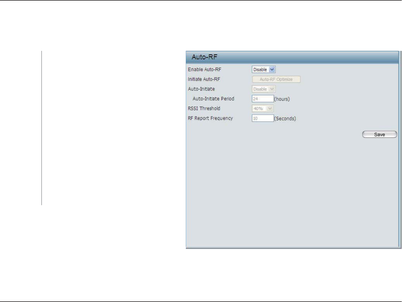
In this windows, users can view and congure the automatic radio frequency settings as well as congure the the auto-initiate
period and threshold values. Click the Save button to accept the changes made.
Enable: Auto-RF:
Initiate Auto-RF:
Auto-Initiate:
Auto-Initiate
Period:
RSSI Threshold:
RF Report
Frequency:
Select to Enable or Disable the auto-RF feature
here.
Click the Auto-RF Optimize button to initiate the
auto-RF optimization feature.
Select the Enable or Disable the auto-initiate
feature here.
After enabling the auto-initiate option, the auto-
initiate period value can be entered here. This value
must be between 1 and 24 hours.
Select the RSSI threshold value here. This value is
listed in the drop-down menu in increments of 10%
from 10% to 100%.
Enter the RF report frequency value here.
Auto-RF
53D-Link DAP-2553 User Manual
Section 3 - Conguration
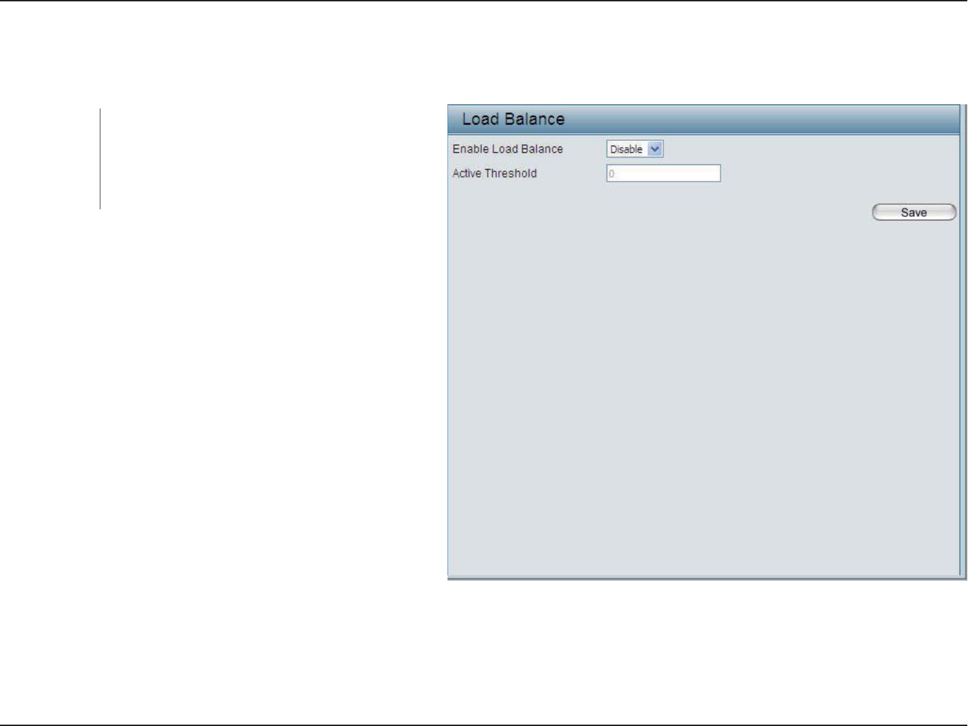
In this window, users can view and congure the AP array’s load balancing settings. Click the Save button to accept the changes
made.
Enable Load
Balance:
Active Threshold:
Select to Enable or Disable the load balance
feature here.
Enter the active threshold value here.
Load Balance
54D-Link DAP-2553 User Manual
Section 3 - Conguration
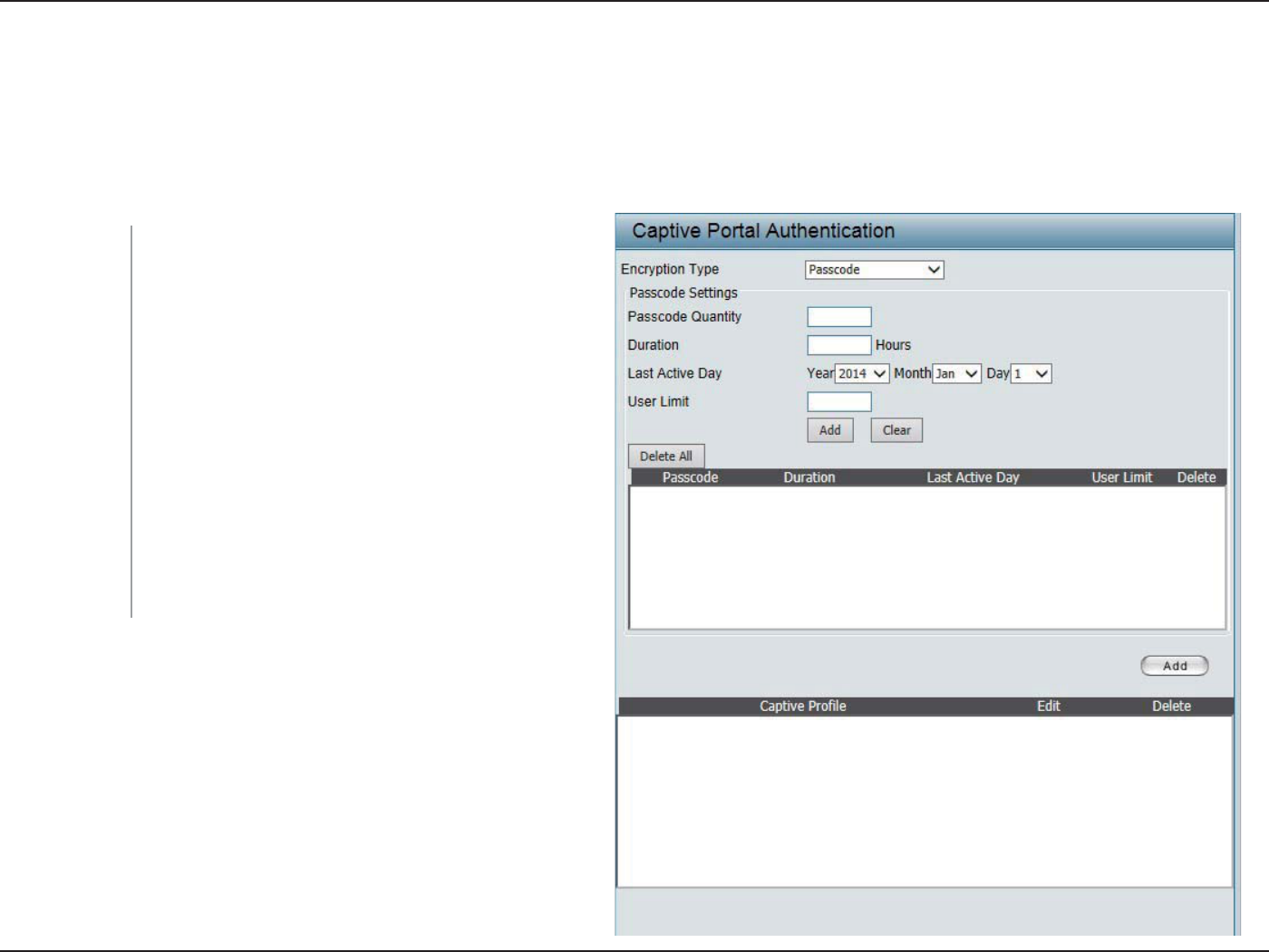
Captive Portal
The Captive Portal is a built-in web authentication server. When a station connects to an AP, the web brower will be redirected
to a web authentication page. In this windows, user can view and congure the Captive Portal settings. Click the Add button
to add a new entry. Click the Delete or Delete All button to remove a specic entry or all the entries congured.
Encryption Type:
Passcode
Quantity:
Duration:
Last Active Day:
User Limit:
Select the captive portal encryption type here.
Options to choose from are Passcode, User Name/
Password, Remote RADIUS, LDAP and POP3. In
this section we’ll discuss the Passcode option.
Enter the number of Passcode that will be used here.
Enter the duration value, in hours, for this Passcode.
Select the last active date for this Passcode here.
Year, Month and Day selections can be made.
Enter the maximum amount of users that can use
this Passcode at the same time.
Authentication Settings - Passcode
55D-Link DAP-2553 User Manual
Section 3 - Conguration
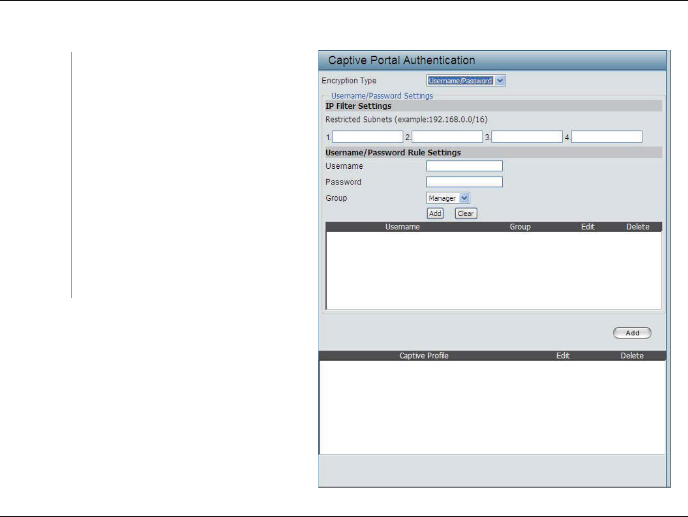
Encryption Type:
Restricted
Subnets:
Username:
Password:
Group:
Select the captive portal encryption type here.
Options to choose from are Passcode, User Name/
Password, Remote RADIUS, LDAP and POP3. In
this section we’ll discuss the User Name/Password
option.
Enter the restricted subnets here. Access to these
subnets will denied to guest accounts. Up to four
restricted subnet entries can be dened.
Enter the username for the new account here.
Enter the password for the new account here.
Select the group for the new account here. Options
to choose from are Manager and Guest. Guest
accounts will have limited access.
Authentication Settings - User Name/Password
56D-Link DAP-2553 User Manual
Section 3 - Conguration
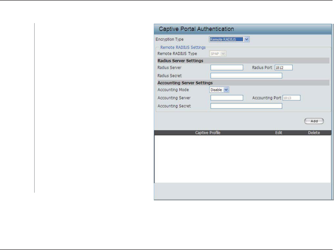
Encryption Type:
Remote RADIUS
Type:
RADIUS Server:
RADIUS Port:
RADIUS Secret:
Accounting
Mode:
Accounting
Server:
Accounting Port:
Accounting
Secret:
Select the captive portal encryption type here.
Options to choose from are Passcode, User Name/
Password, Remote RADIUS, LDAP and POP3.
In this section we’ll discuss the Remote RADIUS
option.
Select the remote RADIUS server type here.
Currently, only SPAP will be used.
Enter the RADIUS server’s IP address here.
Enter the RADIUS server’s port number here.
Enter the RADIUS server’s shared secret here.
Select to Enable or Disable the accounting mode
here.
Enter the accounting server’s IP address here.
Enter the accounting server’s port number here.
Enter the accounting server’s shared serect here.
Authentication Settings - Remote RADIUS
57D-Link DAP-2553 User Manual
Section 3 - Conguration
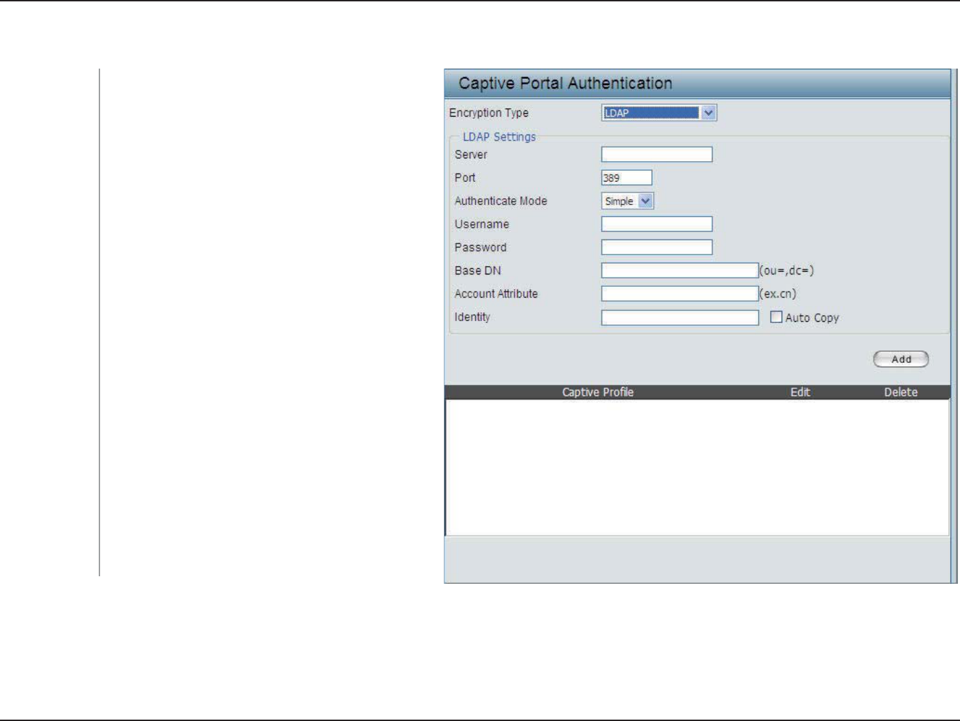
Encryption Type:
Server:
Port:
Authenticate
Mode:
Username:
Password:
Base DN:
Account Attribute:
Identity:
Select the captive portal encryption type here.
Options to choose from are Passode, User Name/
Password, Remote RADIUS, LDAP and POP3. In
this section we’ll discuss the LDAP option.
Enter the LDAP server’s IP address or domain name
here.
Enter the LDAP server’s port number here.
Select the authentication mode here. Options to
choose from are Simple and TLS.
Enter the LDAP server account’s username here.
Enter the LDAP server account’s password here.
Enter the administrator’s domain name here.
Enter the LDAP account attribute string here. This
string will be used to search for clients.
Enter the identity’s full path string here. Alternatively,
select the Auto Copy checkbox to automatically
add the generic full path of the web page in the
identity eld.
Authentication Settings - LDAP
58D-Link DAP-2553 User Manual
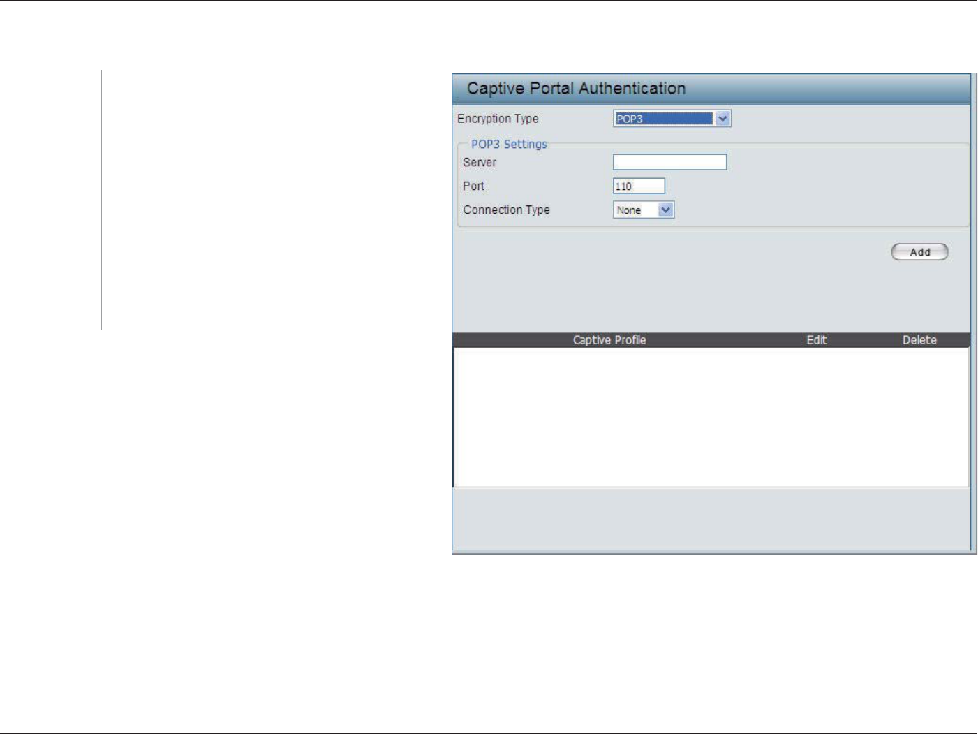
Section 3 - Conguration
Encryption Type:
Server:
Port:
Connection Type:
Select the captive portal encryption type here.
Options to choose from are Passode, User Name/
Password, Remote RADIUS, LDAP and POP3. In
this section we’ll discuss the Passcode option.
Enter the POP3 server’s IP address or domain name
here.
Enter the POP server’s port number here.
Select the connection type here. Options to choose
from are None and SSL/TLS.
Authentication Settings - POP3
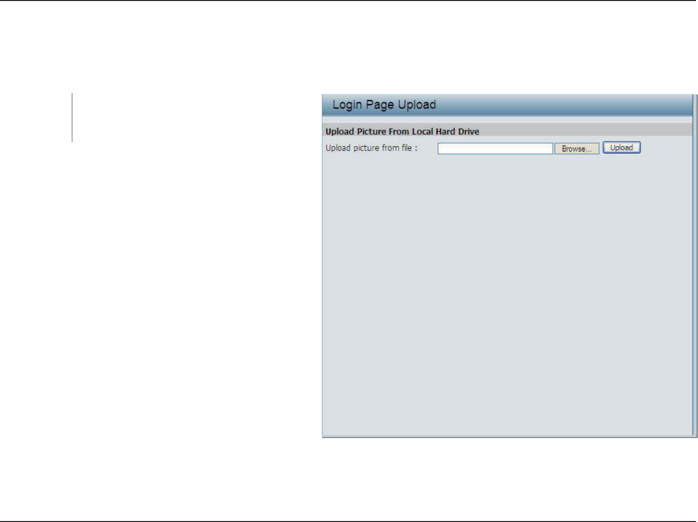
59D-Link DAP-2553 User Manual
Section 3 - Conguration
In this window, users can upload a custom login page picture that will be used by the captive portal feature. Click the Browse
button to navigate to the image le, located on the managing computer and then click the Upload button to initiate the upload.
Upload picture
from le:
In this eld the path to the image le, that will be
uploaded, will be displayed. Alternatively, the path
can be manually entered here.
Login Page Upload
60D-Link DAP-2553 User Manual
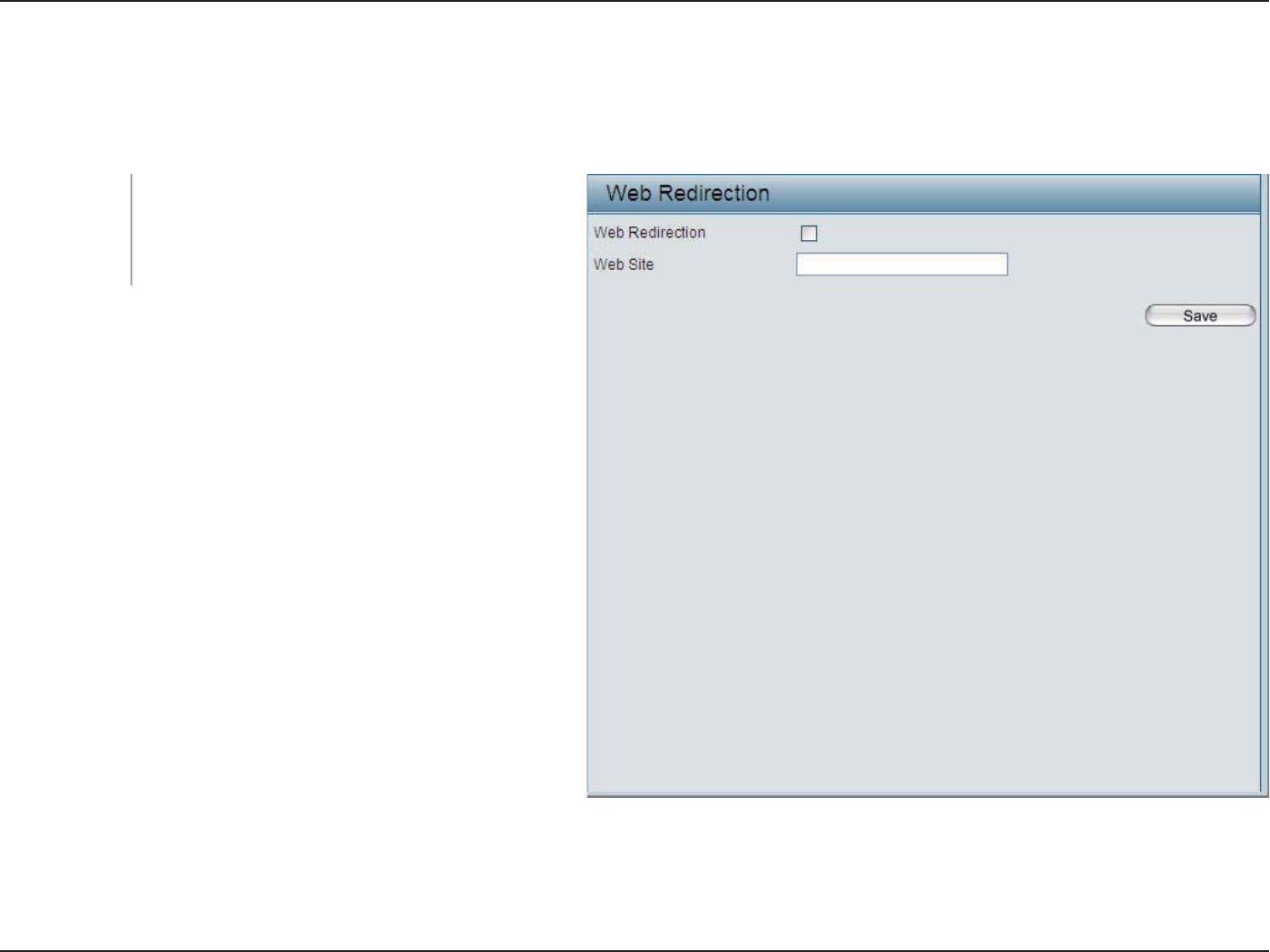
Section 3 - Conguration
Web Redirection
In this windows, users can view and congure the Web redirection settings for the captive portal hosted by this access
point. Wireless clients will be redirected to this web site prior and after authentication. Click the Save button to accept the
changes made.
Web Redirection:
Web Site:
Select this checkbox to enable the Web redirection
feature.
Enter the destination web site’s address here.
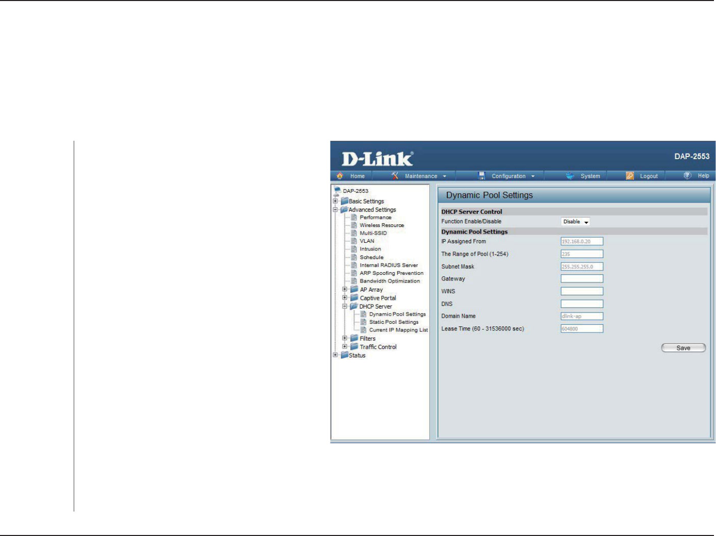
61D-Link DAP-2553 User Manual
Section 3 - Conguration
DHCP Server
Dynamic Pool Settings
The DHCP address pool denes the range of the IP address that can be assigned to stations in the network. A Dynamic Pool
allows wireless stations to receive an available IP with lease time control. If needed or required in the network, the DAP-2553
is capable of acting as a DHCP server.
Dynamic Host Configuration Protocol (DHCP)
assigns dynamic IP addresses to devices on
the network. This protocol simplifies network
management and allows new wireless devices to
receive IP addresses automatically without the
need to manually assign new IP addresses. Select
Enable to allow the DAP-2553 to function as a
DHCP server.
Input the rst IP address available for assignment
on your network.
Enter the number of IP addresses available for
assignment. IP addresses are increments of the IP
address specied in the “IP Assigned From” eld.
All devices in the network must have the same
subnet mask to communicate. Enter the submask
for the network here.
Enter the IP address of the gateway on the
network.
Specify the Windows Internet Naming Service (WINS) server address for the wireless network. WINS is a system that determines
the IP address of a network computer that has a dynamically assigned IP address.
Function En-
able/Disable:
IP Assigned
From:
The Range of
Pool (1-254):
Subnet Mask:
Gateway:
WINS:

62D-Link DAP-2553 User Manual
Section 3 - Conguration
Enter the IP address of the Domain Name System (DNS) server. The DNS server translates domain names such as www.dlink.
com into IP addresses.
Enter the domain name of the network, if applicable. (An example of a domain name is: www.dlink.com.)
The lease time is the period of time before the DHCP server will assign new IP addresses.
DNS:
Domain Name:
Lease Time
(60-31536000
sec):
63D-Link DAP-2553 User Manual
Section 3 - Conguration
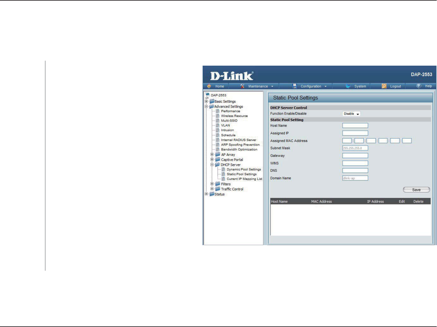
Static Pool Setting
The DHCP address pool denes the range of IP addresses that can be assigned to stations on the network. A static pool allows
specic wireless stations to receive a xed IP without time control.
Dynamic Host Configuration Protocol (DHCP)
assigns IP addresses to wireless devices on
the network. This protocol simplies network
management and allows new wireless devices
to receive IP addresses automatically without
the need to manually assign IP addresses. Select
Enable to allow the DAP-2553 to function as a
DHCP server.
Use the Static Pool Settings to assign the same
IP address to a device every time you start up.
The IP addresses assigned in the Static Pool list
must NOT be in the same IP range as the Dynamic
Pool. After you have assigned a static IP address
to a device via its MAC address, click Save; the
device will appear in the Assigned Static Pool at
the bottom of the screen. You can edit or delete
the device in this list.
Enter the MAC address of the device requesting
association here.
Dene the submask of the IP address specied in the “IP Assigned From” eld.
Function En-
able/Disable:
Assigned IP:
Assigned MAC
Address:
Subnet Mask:

64D-Link DAP-2553 User Manual
Section 3 - Conguration
Specify the Gateway address for the wireless network.
Specify the Windows Internet Naming Service (WINS) server address for the wireless network. WINS is a system that determines
the IP address of a network computer with a dynamically assigned IP address, if applicable.
Enter the Domain Name System (DNS) server address for the wireless network. The DNS server translates domain names such as
www.dlink.com into IP addresses.
Specify the domain name for the network.
Gateway:
WINS:
DNS:
Domain Name:
65D-Link DAP-2553 User Manual
Section 3 - Conguration
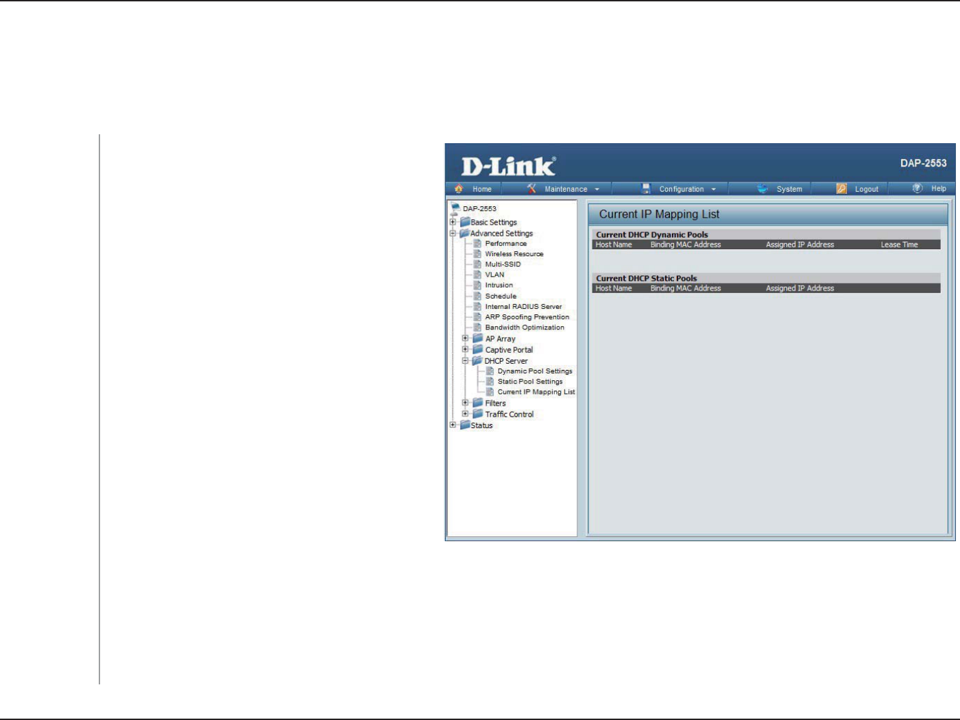
Current IP Mapping List
This window displays information about the current assigned DHCP dynamic and static IP address pools. This information is
available when you enable DHCP server on the AP and assign dynamic and static IP address pools.
These are IP address pools the DHCP server has
assigned using the dynamic pool setting.
The host name of a device on the network that is
assigned an IP address from the DHCP dynamic
pool.
The MAC address of a device on the network that
is assigned an IP address from the DHCP dynamic
pool.
The current corresponding DHCP-assigned IP
address of the device.
The length of time that the dynamic IP address
will be valid.
These are the IP address pools of the DHCP server
assigned through the static pool settings.
The host name of a device on the network that is
assigned an IP address from the DHCP dynamic pool.
The MAC address of a device on the network that is within the DHCP static IP address pool.
The current corresponding DHCP-assigned static IP address of the device.
Current DHCP
Dynamic
Prole:
Host Name:
Binding MAC
Address:
Assigned IP
Address:
Lease Time:
Current DHCP
Static Pools:
Host Name:
Binding MAC
Address:
Assigned IP
Address:
66D-Link DAP-2553 User Manual
Section 3 - Conguration
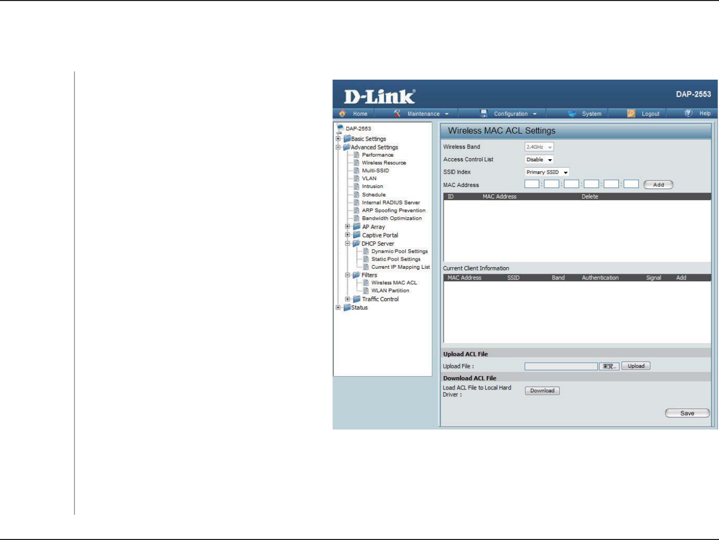
Filters
Wireless MAC ACL
Displays the current wireless band rate.
Select Disable to disable the lters function.
Select the SSID for Wireless MAC ACL .
Select Accept to accept only those devices with
MAC addresses in the Access Control List. All
other devices not on the list will be rejected.
Select Reject to reject the devices with MAC
addresses on the Access Control List. All other
devices not on the list will be accepted.
Enter each MAC address that you wish to include
in your lter list, and click Save.
When you enter a MAC address, it appears in this
list. Highlight a MAC address and click Delete to
remove it from this list.
You may create an ACL list and upload it to the
access point instead of manually entering the
information. Once created, click the Browse
button and locate your le. Select it and then
click Upload.
Click Download to export the ACL to a le on
your computer.
Wireless Band:
Access Control
List:
SSID Index :
MAC Address:
MAC Address
List:
Upload ACL File:
Download ACL
File:
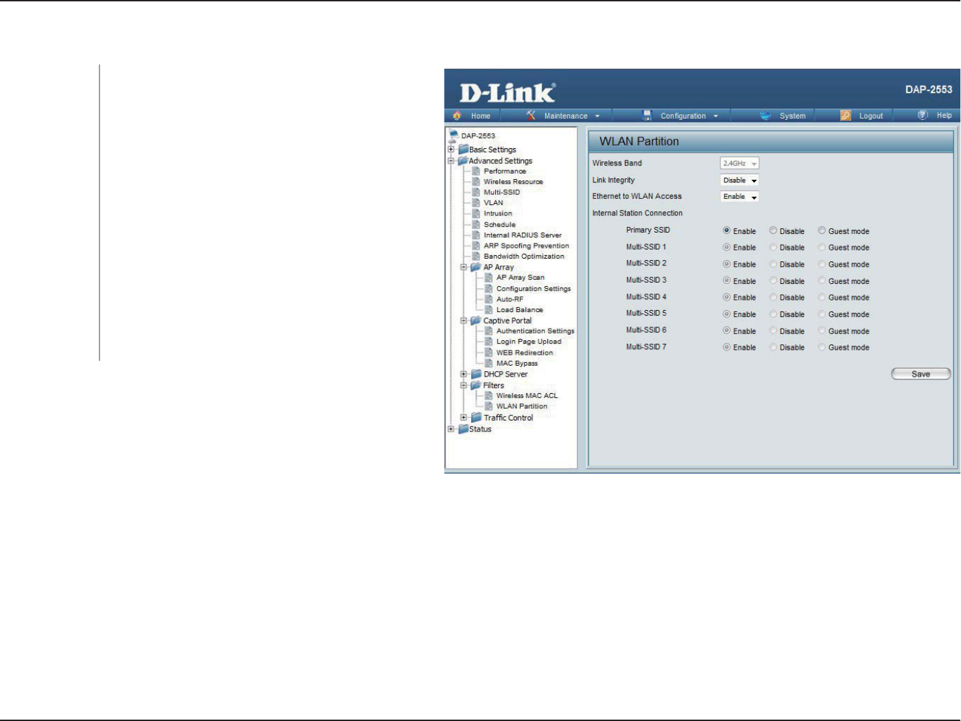
67D-Link DAP-2553 User Manual
Section 3 - Conguration
WLAN Partition
Displays the current wireless band rate.
Select Enable or Disable.
The default is Enable. When disabled, all data
from the Ethernet to associated wireless devices
will be blocked. Wireless devices can still send
data to the Ethernet.
The default value is Enable, which allows
stations to intercommunicate by connecting
to a target AP. When disabled, wireless stations
cannot exchange data on the same Multi-SSID. In
Guest mode, wireless stations cannot exchange
data with any station on your network
Wireless Band:
Link Integrity:
Ethernet to
WLAN Access:
Internal Station
Connection:
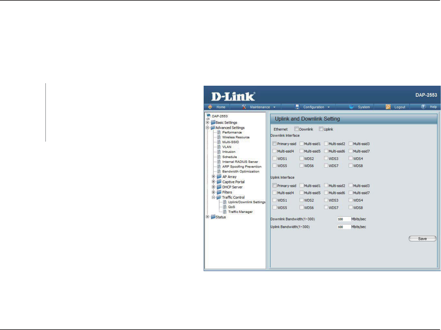
68D-Link DAP-2553 User Manual
Section 3 - Conguration
Trac Control
The uplink/downlink setting allows users to customize the downlink and uplink interfaces including specifying downlink/uplink
bandwidth rates in Mbits per second. These values are also used in the QoS and Trac Manager windows. Once the desired
uplink and downlink settings are nished, click the Save button to let your changes take eect.
Downlink
Bandwidth:
Uplink Bandwidth:
The downlink bandwidth in Mbits per second.
Uplink Bandwidth: The uplink bandwidth in Mbits
per second.
Uplink/Downlink Setting
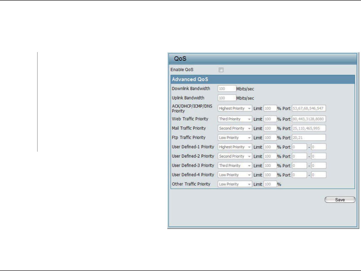
69D-Link DAP-2553 User Manual
Section 3 - Conguration
Quality of Service (QoS) enhances the experience of using a network by prioritizing the trac of dierent applications. The
DAP-2553 supports four priority levels. Once the desired QoS settings are nished, click the Save button to let your changes
take eect.
Enable QoS:
Downlink
Bandwidth:
Uplink
Bandwidth:
Check this box to allow QoS to prioritize trac.
Use the drop-down menus to select the four
levels of priority. Click the Save button when you
are nished.
Downlink Bandwidth: The downlink bandwidth
in Mbits per second. This value is entered in the
Uplink/Downlink Setting window.
Uplink Bandwidth: The uplink bandwidth in
Mbits per second. This value is entered in the
Uplink/Downlink Setting window.
QoS
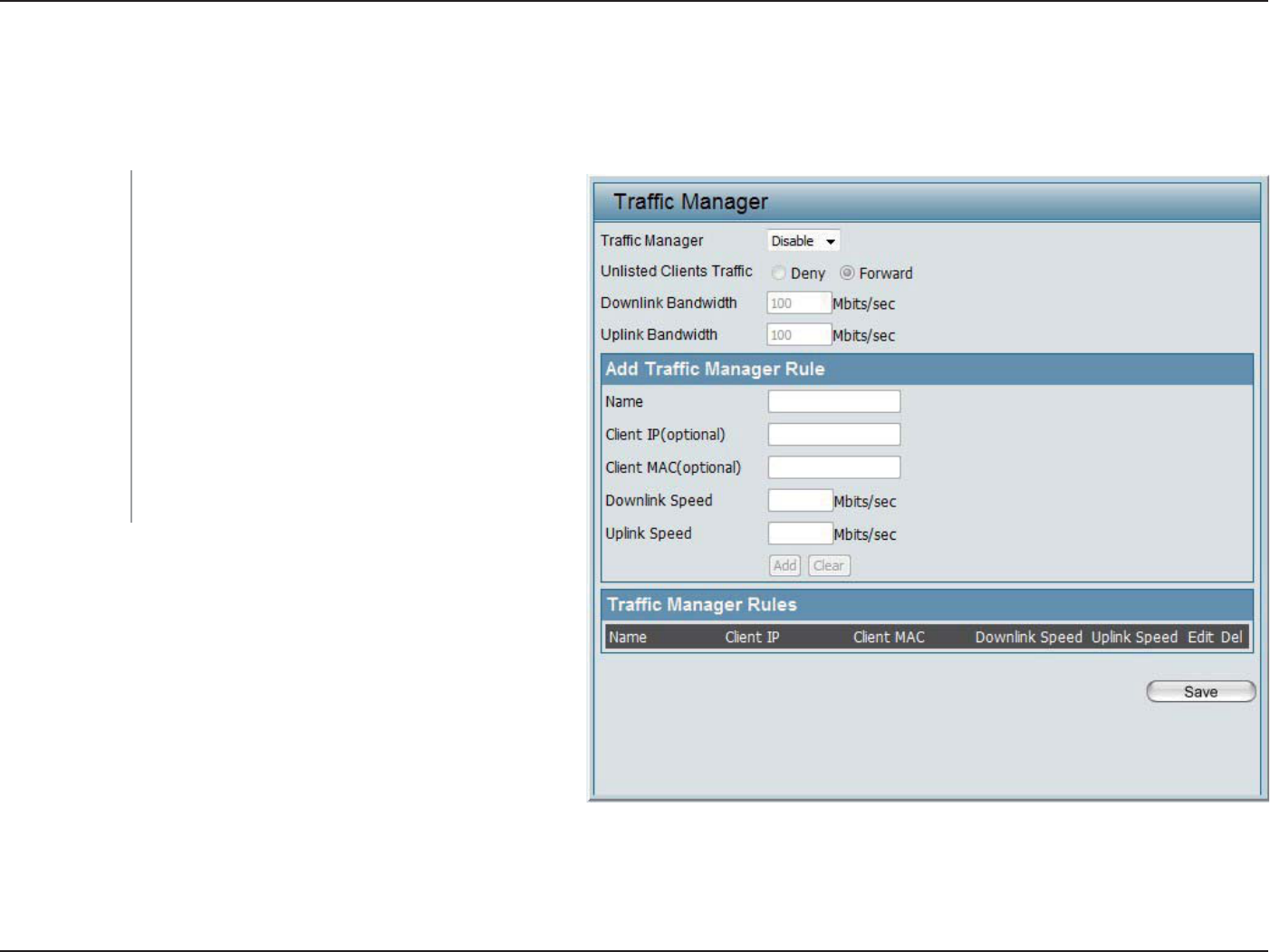
70D-Link DAP-2553 User Manual
Section 3 - Conguration
The trac manager feature allows users to create trac management rules that specify how to deal with listed client trac
and specify downlink/ uplink speed for new trac manager rules. Click the Save button to let your changes take eect.
Trac Manager:
Unlisted Client
Trac:
Downlink
Bandwidth:
Uplink
Bandwidth:
Use the drop-down menu to Enable the trac
manager feature.
Select Deny or Forward to determine how to deal
with unlisted client trac.
The downlink bandwidth in Mbits per second.
This value is entered in the Uplink/Downlink
Setting window.
Uplink Bandwidth:The uplink bandwidth in Mbits
per second. This value is entered in the Uplink/
Downlink Setting window.
Trac Manager
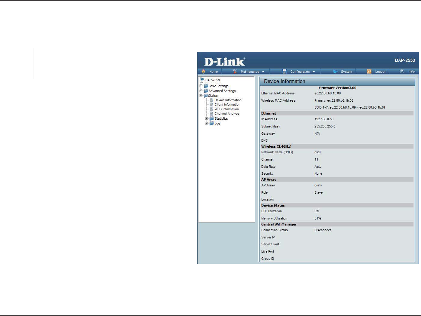
71D-Link DAP-2553 User Manual
Section 3 - Conguration
Status
Device Information
This read-only window displays the configuration
settings of the DAP-2553, including the firmware
version and the device's MAC address.
Device
Information:
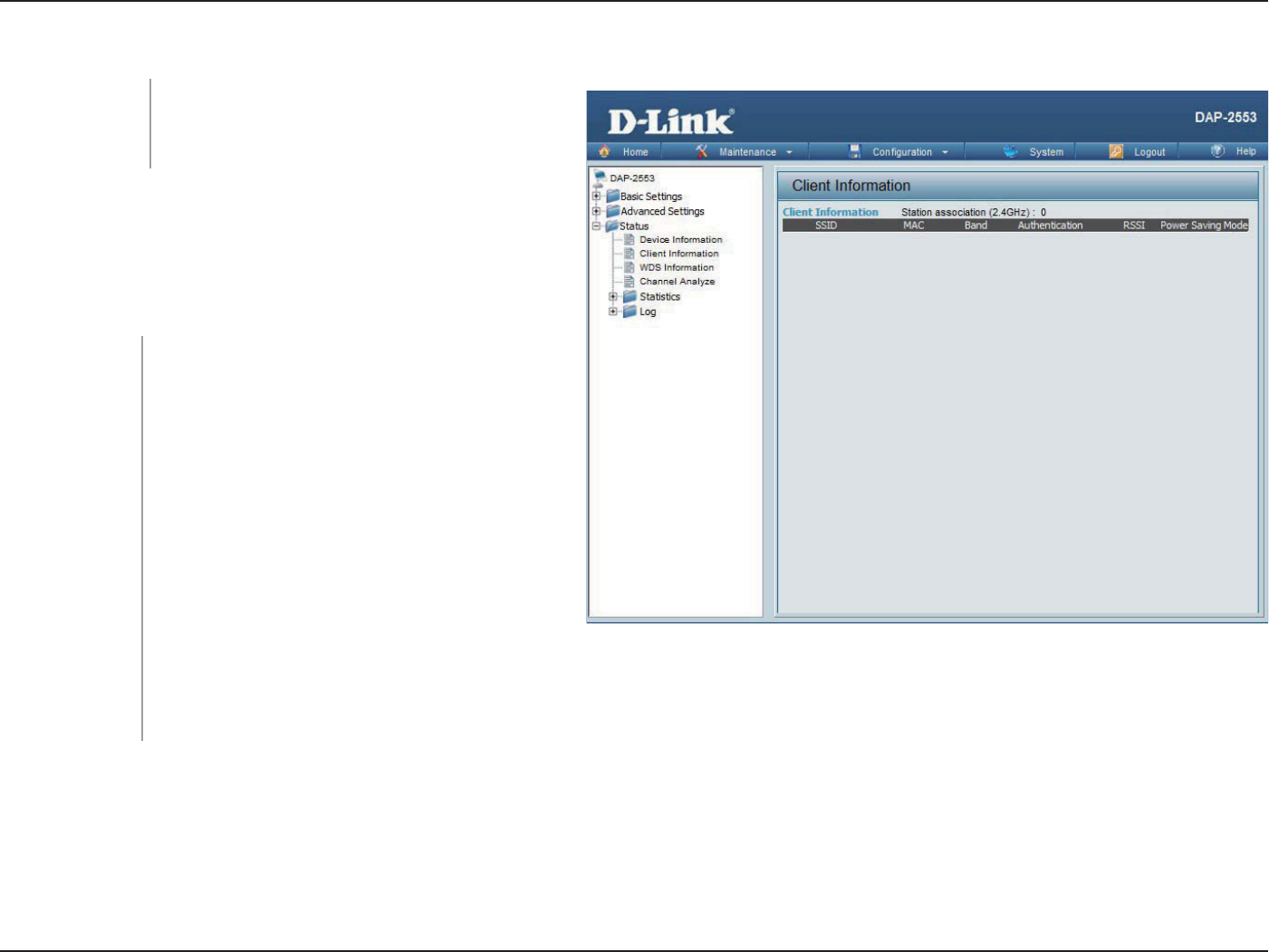
72D-Link DAP-2553 User Manual
Section 3 - Conguration
The following information is available for each client
communicating with the DAP-2553.
Client Information
This window displays the wireless client
information for clients currently connected
to the DAP-2553.
Client Information:
Displays the SSID of the client.
Displays the MAC address of the client.
Displays the wireless band that the client is
connected to.
Displays the type of authentication being
used.
Displays the client's signal strength (received
signal strength indicator).
Displays the status of the power saving
feature.
SSID:
MAC:
Band:
Authentication:
RSSI:
Power Saving
Mode:
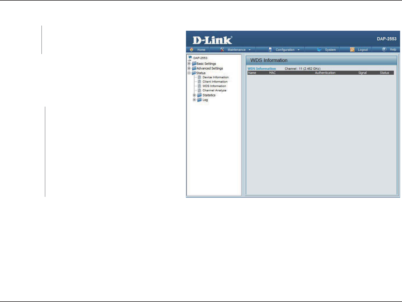
73D-Link DAP-2553 User Manual
Section 3 - Conguration
WDS Information
The following information is available for each client
communicating with the DAP-2553.
This window displays the Wireless
Distribution System information for clients
currently connected to the DAP-2553.
WDS
Information:
Displays the SSID of the client.
Displays the MAC address of the client.
Displays the type of authentication being
used.
Displays the client's signal strength.
Displays the status of the power saving
feature.
Name:
MAC:
Authentication:
Signal:
Status:
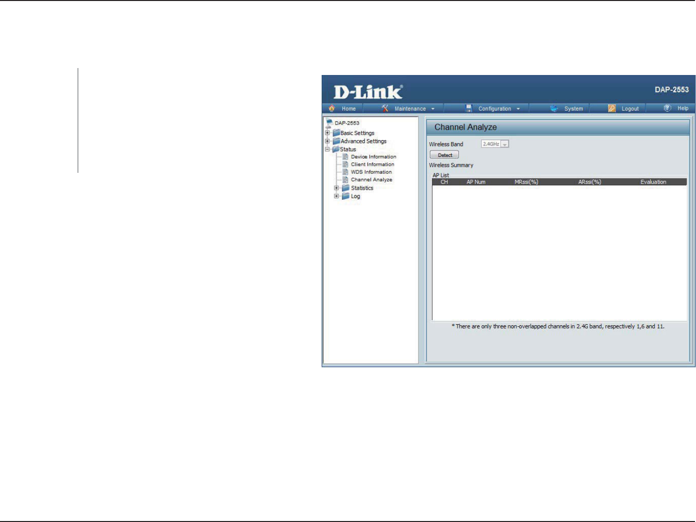
74D-Link DAP-2553 User Manual
Section 3 - Conguration
Channel Analyze
Wireless Band:
Detect:
AP List:
Select 2.4GHz in default.
Click the Detect button to scan.
This will list the transmitting channels and
quality.
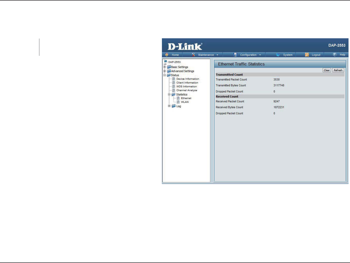
75D-Link DAP-2553 User Manual
Section 3 - Conguration
Stats
Ethernet
This page displays transmitted and received
count statistics for packets and bytes.
Ethernet Trac
Statistics:
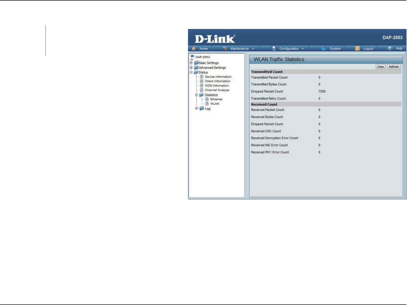
76D-Link DAP-2553 User Manual
Section 3 - Conguration
WLAN Trac
This page displays wireless network statistics
for data throughput, transmitted and received
frames, and frame errors.
WLAN Trac
Statistics:
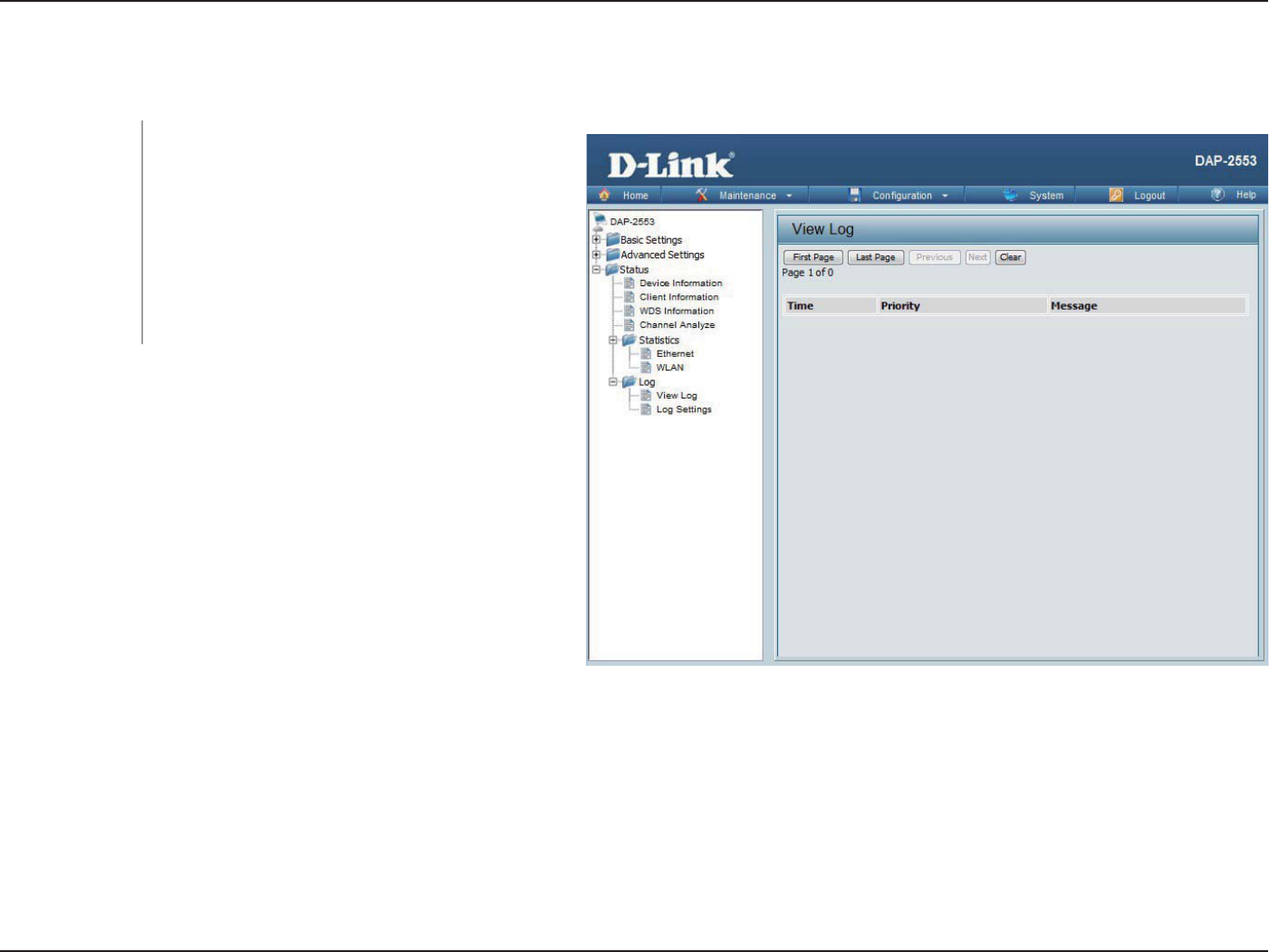
77D-Link DAP-2553 User Manual
Section 3 - Conguration
Log
View Log
The AP’s embedded memory displays system
and network messages including a time stamp
and message type. The log information includes
but is not limited to the following items: cold
start AP, upgrading rmware, client associate
and disassociate with AP, and web login. The
web page holds up to 500 logs.
View Log:
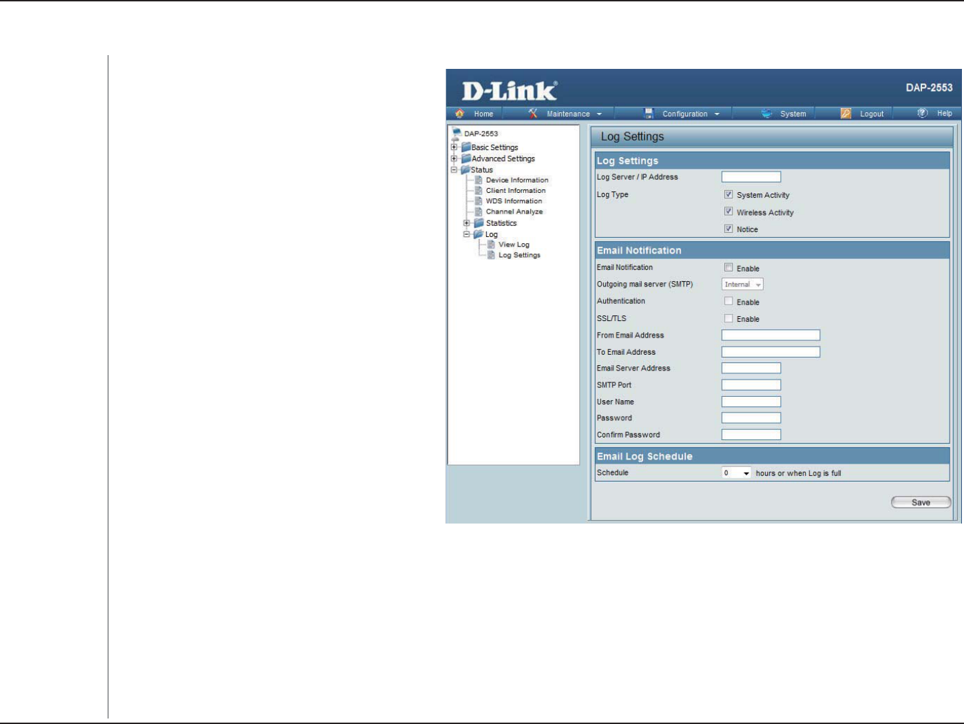
78D-Link DAP-2553 User Manual
Section 3 - Conguration
Log Settings
Enter the IP address of the server you would
like to send the DAP-2553 log to.
Check the box for the type of activity you want
to log. There are three types: System Activity,
Wireless Activity, and Notice.
Check to enable Email notication.
Select the SMTP server from the drop-down
menu.
Check to enable authentication.
Check to enable SSL/TLS authentication.
Enter the “From” email address.
Enter the destination email address.
Enter the Email Server Address.
Enter the SMTP port.
Enter your email username.
Enter your email password.
Enter your email password again.
Select when to send the log to your email (in
hours). You will receive an email when the log
is full too.
Log Server/IP
Address:
Log Type:
Email Notication:
Outgoing Mail
Server (SMTP):
Authentication:
SSL / TLS:
From Email
Address:
To Email Address:
Email Server
Address:
SMTP Port:
Username:
Password:
Conrm
Password:
Schedule:
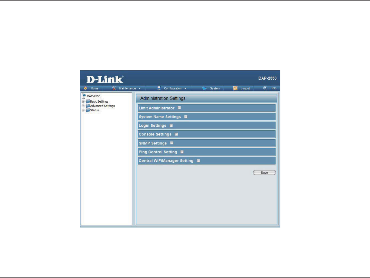
79D-Link DAP-2553 User Manual
Section 3 - Conguration
Check one or more of the seven main categories to display the various hidden administrator parameters and settings
displayed on the next seven pages.
Maintenance
Administration Settings
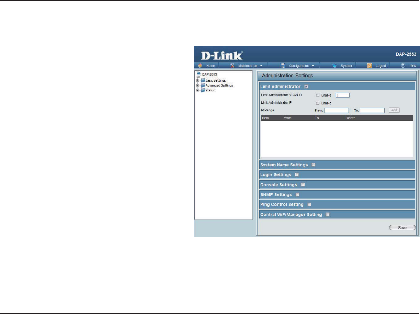
80D-Link DAP-2553 User Manual
Section 3 - Conguration
Limit Administrator
Each of the seven main categories display various hidden administrator parameters and settings.
Check the box provided and the enter the
specic VLAN ID that the administrator will be
allowed to log in from.
Check to enable the Limit Administrator IP
address.
Enter the IP address range that the administrator
will be allowed to log in from and then click the
Add button.
Limit
Administrator
VLAN ID:
Limit
Administrator IP:
IP Range:
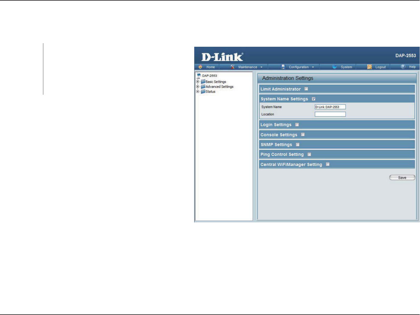
81D-Link DAP-2553 User Manual
Section 3 - Conguration
System Name Settings
Each of the seven main categories display various hidden administrator parameters and settings.
The name of the device. The default name is
D-Link DAP-2553.
The physical location of the device, e.g. 72nd
Floor, D-Link HQ.
System Name:
Location:
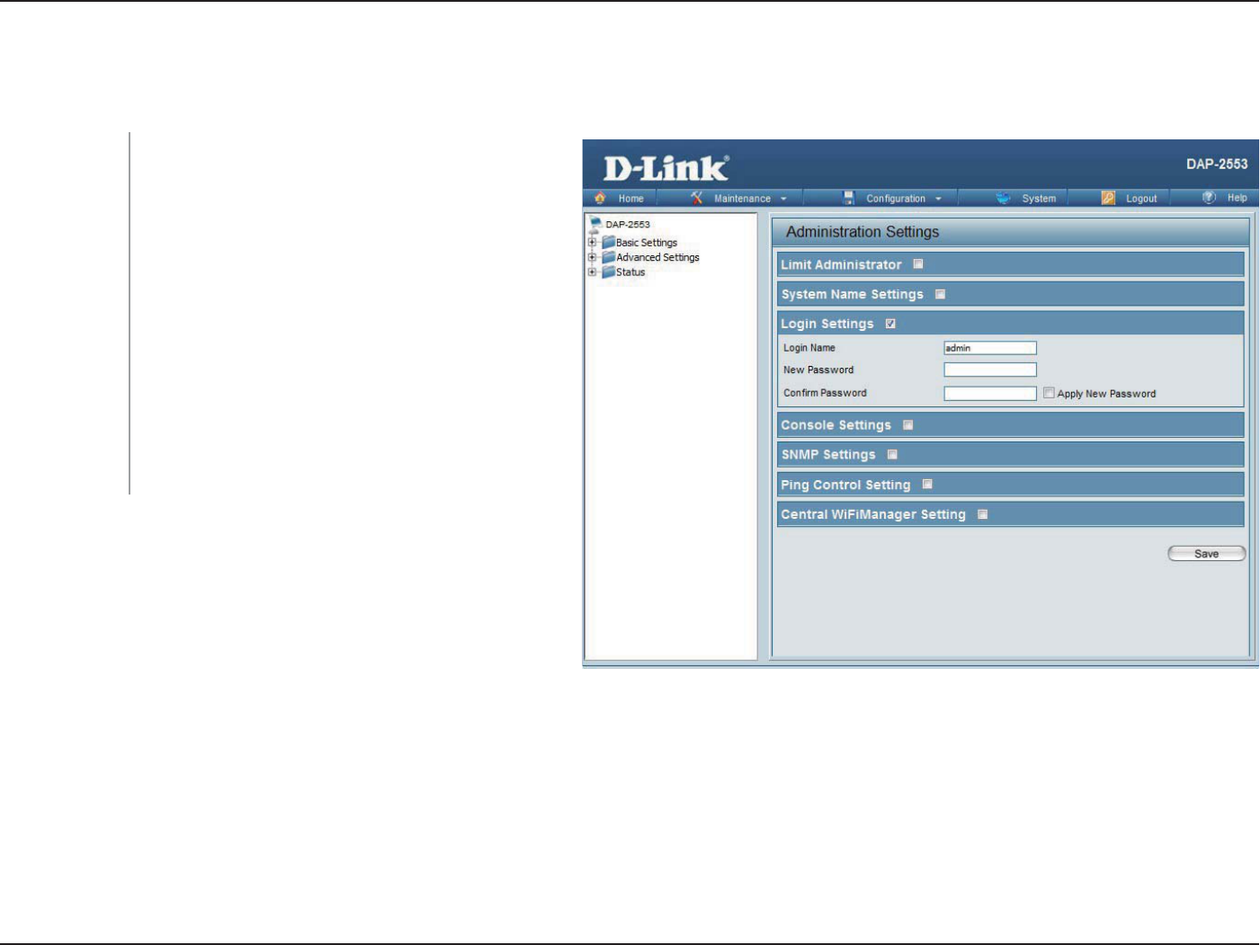
82D-Link DAP-2553 User Manual
Section 3 - Conguration
Login Settings
Each of the seven main categories display various hidden administrator parameters and settings.
Enter a user name. The default is admin.
When changing your password, enter the new
password here. The password is case-sensitive.
“A” is a dierent character than “a.” The length
should be between 0 and 12 characters.
Enter the new password a second time for
conrmation purposes.
Click the box to conrm apply new password
again
Login Name:
New Password:
Conrm
Password:
Apply New
Password :
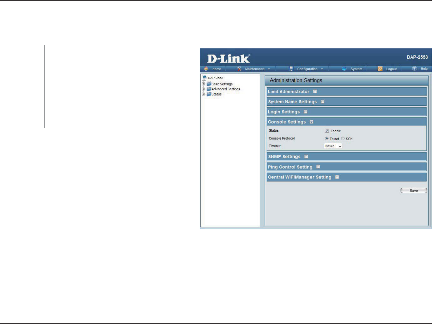
83D-Link DAP-2553 User Manual
Section 3 - Conguration
Console Settings
Each of the seven main categories display various hidden administrator parameters and settings.
Status is enabled by default. Uncheck the box to
disable the console.
Select the type of protocol you would like to use,
Telnet or SSH.
Set to 1 Min, 3 Mins, 5 Mins, 10 Mins, 15 Mins
or Never.
Status:
Console
Protocol:
Timeout:
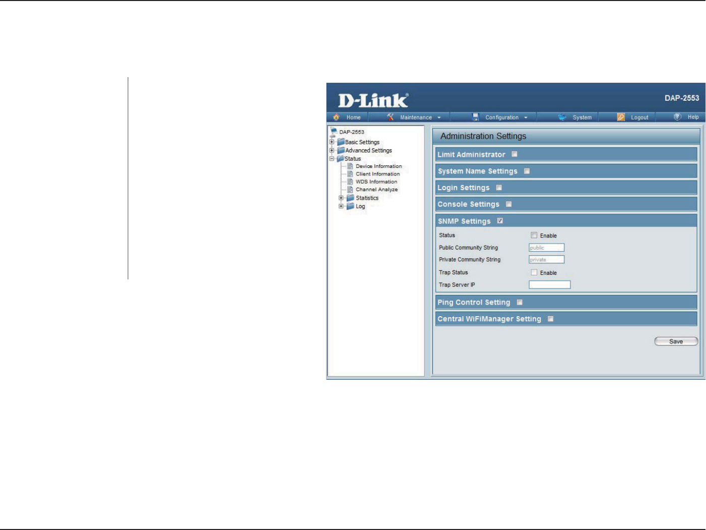
84D-Link DAP-2553 User Manual
Section 3 - Conguration
SNMP Settings
Each of the seven main categories display various hidden administrator parameters and settings.
Check the box to enable the SNMP
functions. This option is disabled by
default.
Enter the public SNMP community
string.
Enter the private SNMP community
string.
Check the box to enable Trap Status.
Enter the Trap Server IP address.
Status:
Public Community String:
Private Community String:
Trap Status:
Trap Server IP:
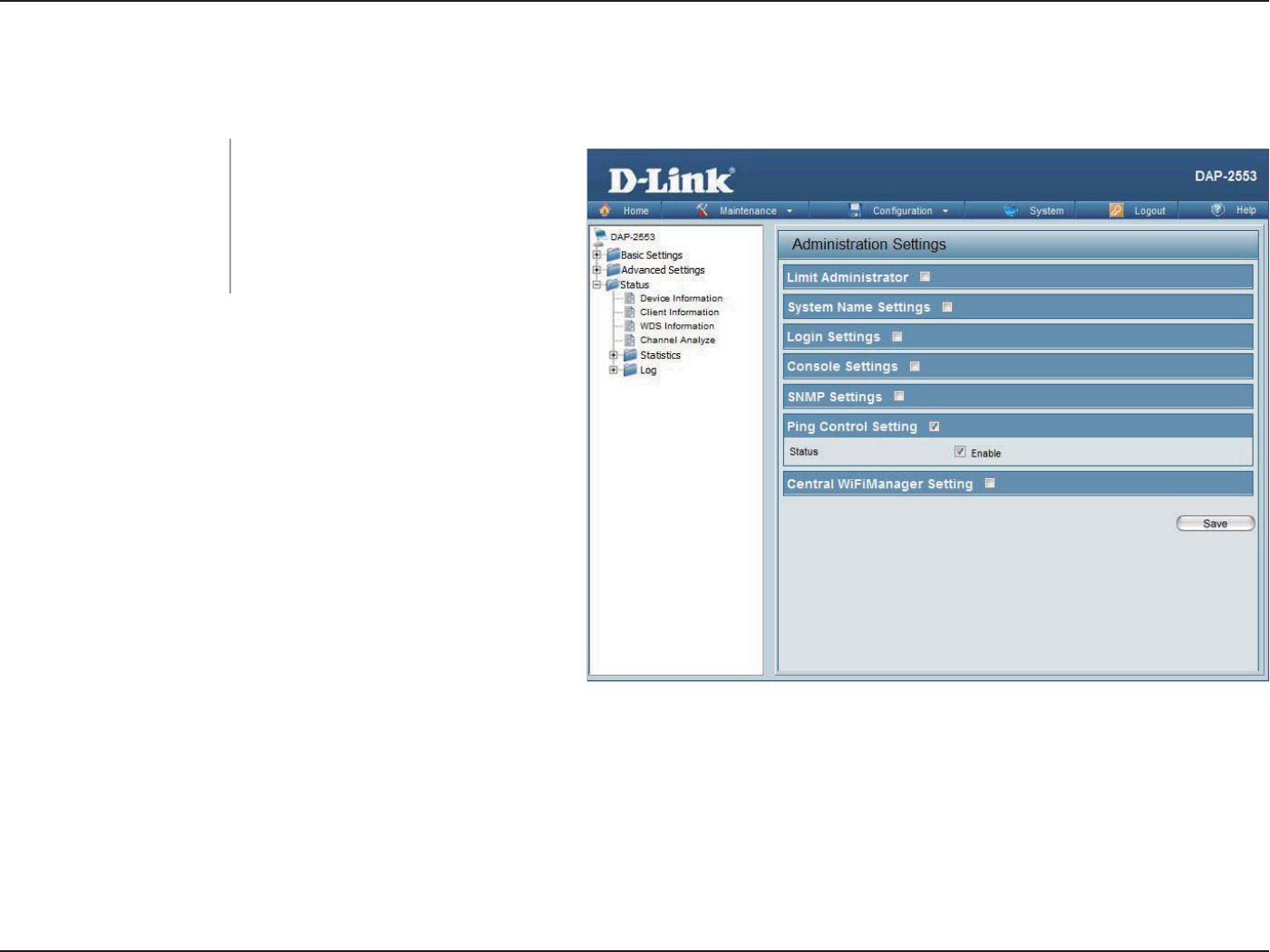
85D-Link DAP-2553 User Manual
Section 3 - Conguration
Ping Control Setting
Each of the seven main categories display various hidden administrator parameters and settings.
Check the box to enable Ping control.
Ping works by sending ICMP “echo
request” packets to the target host
and listening for ICMP echo response
replies. The default is enabled.
Status:
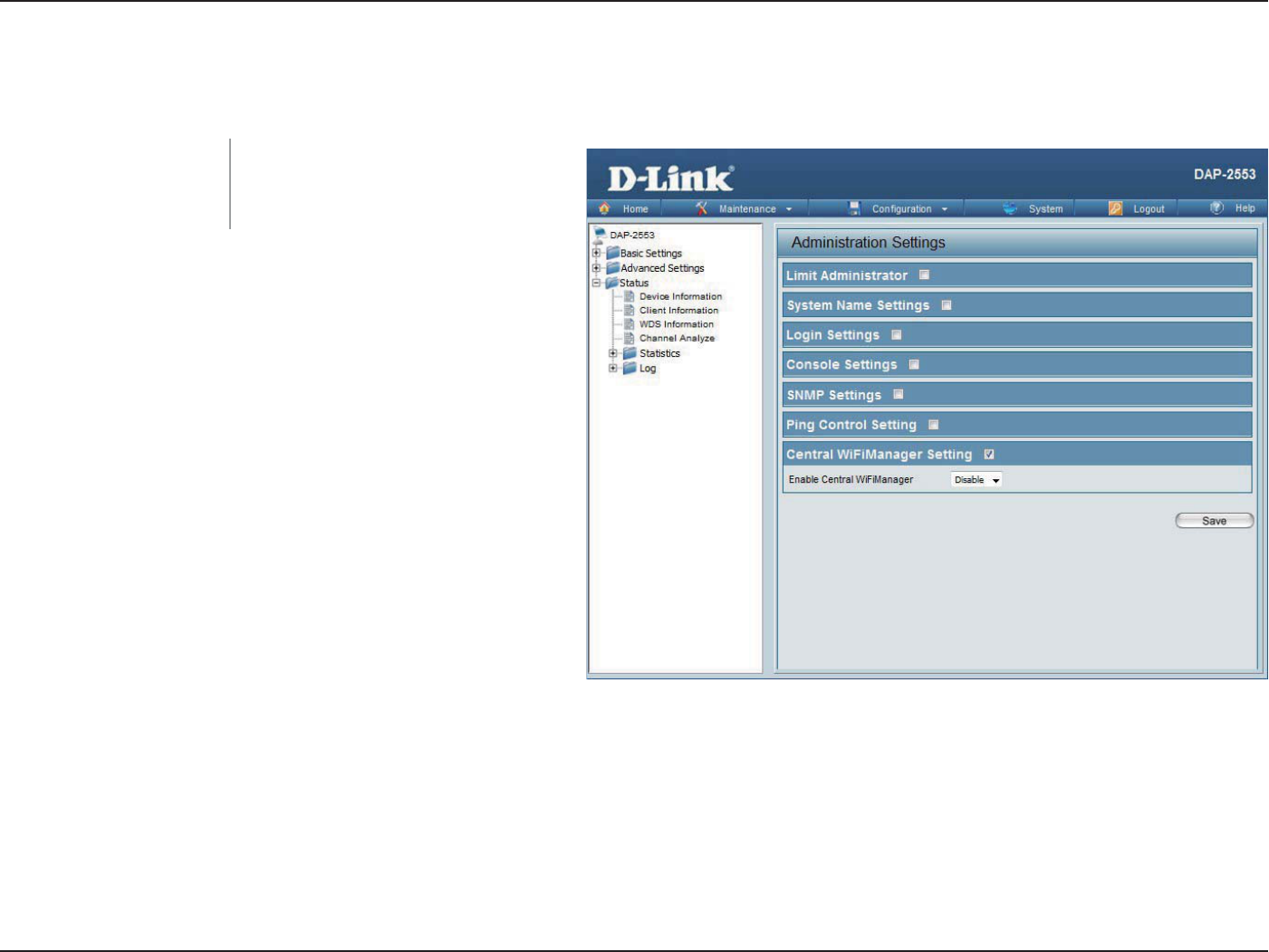
86D-Link DAP-2553 User Manual
Section 3 - Conguration
Ping Control Setting
Each of the seven main categories display various hidden administrator parameters and settings.
Select to enable or disable the
Central WiFiManager.
Enable Central
WiFiManager :
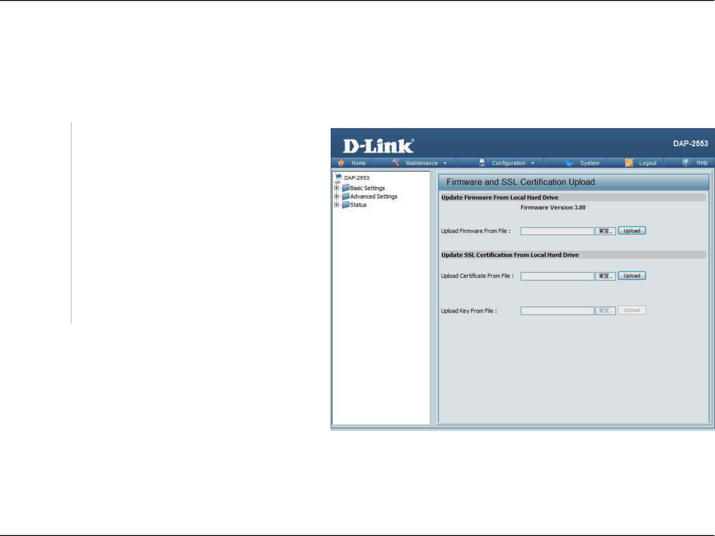
87D-Link DAP-2553 User Manual
Section 3 - Conguration
Firmware and SSL Certication Upload
The current firmware version is displayed
above the le location eld. After downloading
the most recent version of firmware for the
DAP-2553 from http://support.dlink.com to your
local computer, use the Browse button to locate
the rmware le on your computer. Click Upload
to update the rmware version. Please don’t turn
the power o while upgrading.
Click Browse to locate the SSL Certication le on
your local computer. After selecting and opening
the le, click Upload to upload the le to the
DAP-2553.
Upload
Firmware From
Local Hard
Drive:
Upload SSL
Certication
From Local Hard
Drive:
This page allows the user to perform a rmware upgrade. A Firmware upgrade is a function that upgrade the running software
used by the access point. This is a useful feature that prevents future bugs and allows for new features to be added to this
product. Please go to your local D-Link website to see if there is a newer version rmware available.
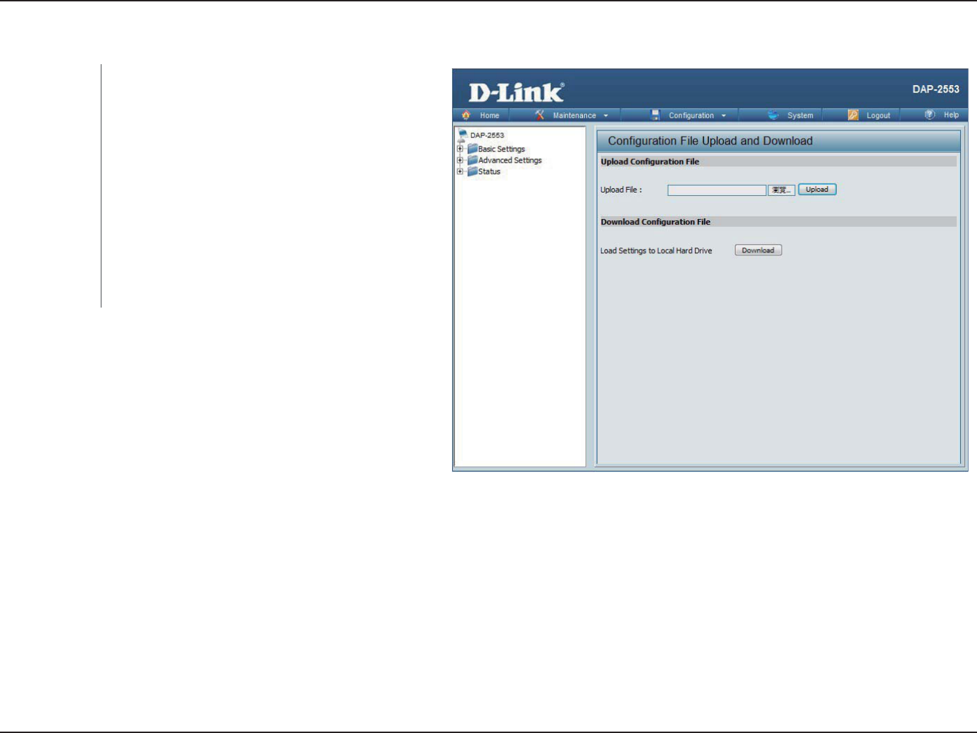
88D-Link DAP-2553 User Manual
Section 3 - Conguration
Conguration File Upload
Click the Browse button to locate a previously
saved conguration le on your local computer.
After selecting the le, click Upload to apply the
conguration settings to the DAP-2553.
Click Download to save the current
DAP-2553 conguration to your local computer.
Note that if you save one conguration with the
administrator’s password now, after resetting
your DAP-2553, and then updating to this saved
conguration le, the password will be gone.
Upload File:
Download
Conguration
File:
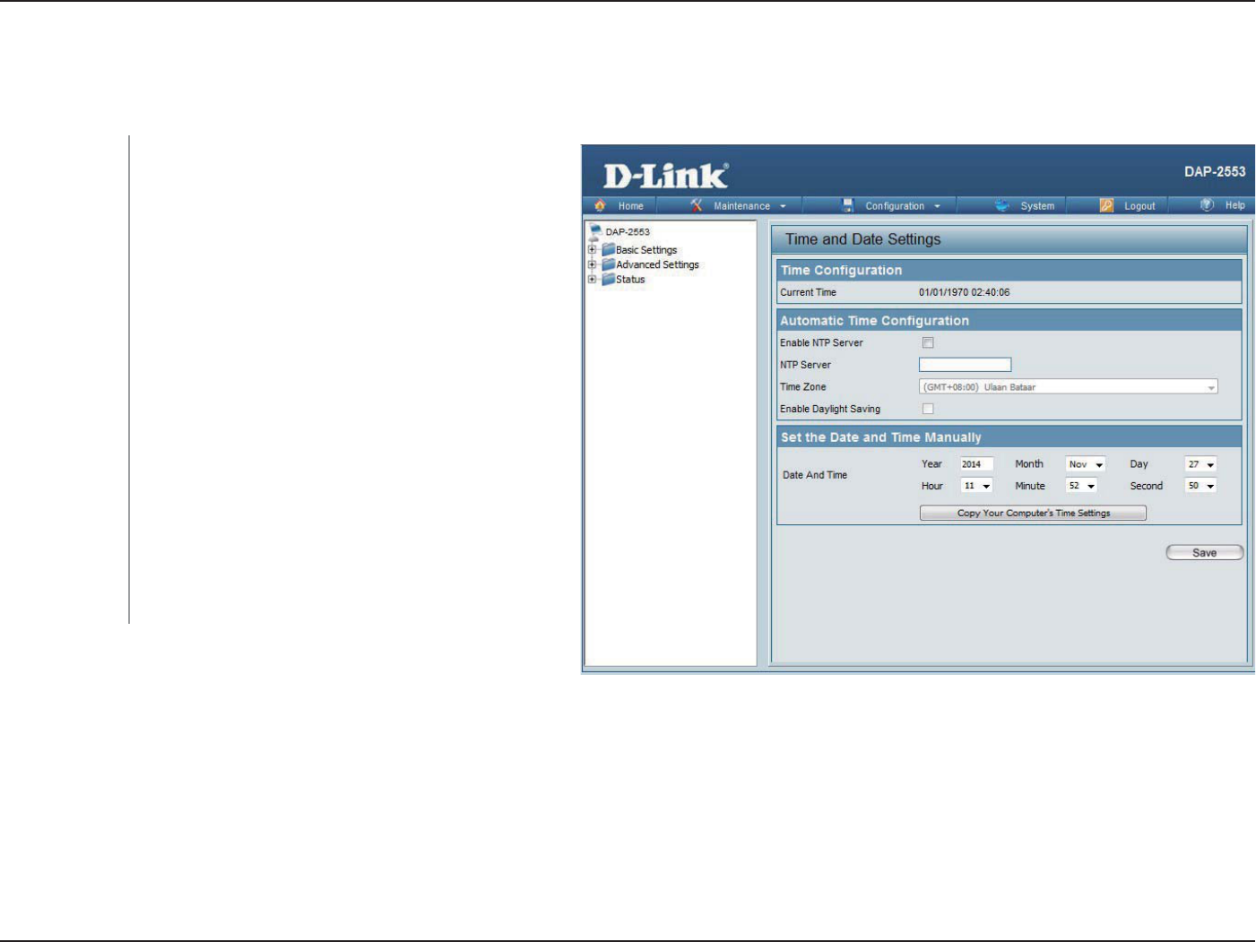
89D-Link DAP-2553 User Manual
Section 3 - Conguration
Time and Date
Enter the NTP server IP, choose the time zone, and enable or disable daylight saving time.
Current Time:
Enable NTP Server:
NTP Server:
Time Zone:
Enable Daylight
Saving:
Set the Date and
Time Manually:
Displays the current time and date settings.
Check to enable the AP to get system time from
an NTP server from the Internet.
Enter the NTP server IP address.
Use the drop-down menu to select your correct
Time Zone.
Check the box to enable Daylight Saving Time.
A user can either manually set the time for the
AP here, or click the Copy Your Computer’s
Time Settings button to copy the time from the
computer in use (Make sure that the computer’s
time is set correctly).
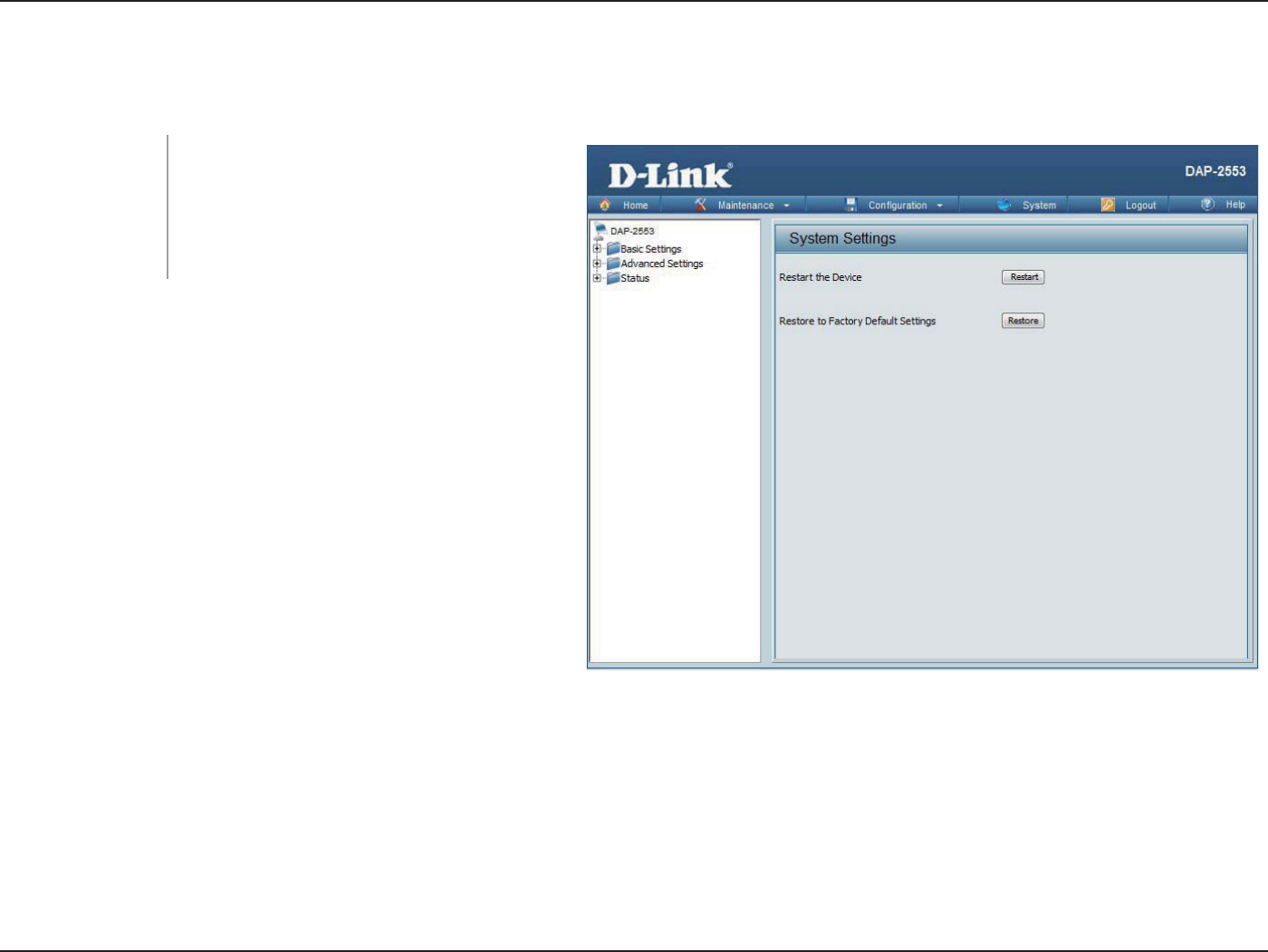
90D-Link DAP-2553 User Manual
Section 3 - Conguration
System
System Settings
Click Restart to restart the DAP-2553.
Click Restore to restore the DAP-2553 back
to factory default settings.
Restart the Device:
Restore to Factory
Default Settings:
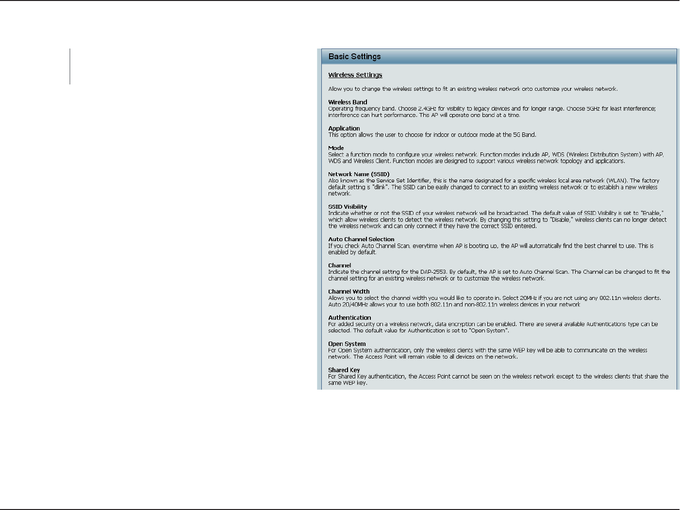
91D-Link DAP-2553 User Manual
Section 3 - Conguration
Help
Scroll down the Help page for topics and
explanations.
Help:

92D-Link DAP-2553 User Manual
Section 6 - Troubleshooting
Troubleshooting
When entering the IP address of the D-Link access point (192.168.0.50 for example), you are not connecting to a website on the Internet or have to
be connected to the Internet. The device has the utility built-in to a ROM chip in the device itself. Your computer must be on the same IP subnet to
connect to the web-based utility.
• Make sure you have an updated Java-enabled web browser. We recommend the following:
• Internet Explorer 7.0 or higher, Chrome, Firefox, or Safari 4 or higher
• Verify physical connectivity by checking for solid link lights on the device. If you do not get a solid link light, try using a dierent cable or connect to a
dierent port on the device if possible. If the computer is turned o, the link light may not be on.
• Disable any internet security software running on the computer. Software rewalls such as Zone Alarm, Black Ice, Sygate, Norton Personal Firewall, and
Windows® rewall may block access to the conguration pages. Check the help les included with your rewall software for more information on disabling
or conguring it.
• Congure your Internet settings:
Go to Start > Settings > Control Panel. Double-click the Internet Options Icon. From the Security tab, click the button to restore the settings to their
defaults.
Click the Connection tab and set the dial-up option to Never Dial a Connection. Click the LAN Settings button. Make sure nothing is checked. Click OK.
Go to the Advanced tab and click the button to restore these settings to their defaults. Click OK three times.
Close your web browser (if open) and open it.
• Access the web management. Open your web browser and enter the IP address of your D-Link access point in the address bar. This should open the login
page for your the web management.
• If you still cannot access the conguration, unplug the power to the access point for 10 seconds and plug back in. Wait about 30 seconds and try accessing
the conguration. If you have multiple computers, try connecting using a dierent computer.
Why can’t I access the web-based conguration utility?
This chapter provides solutions to problems that can occur during the installation and operation of the DAP-2553. Read the following
descriptions if you are having problems. (The examples below are illustrated in Windows® XP. If you have a dierent operating system, the
screenshots on your computer will look similar to the following examples.)
If you forgot your password, you must reset your access point. Unfortunately, this process will change all your settings back to the factory defaults.
To reset the access point, locate the reset button (hole) on the rear panel of the unit. With the access point powered on, use a paperclip to hold the
button down for 10 seconds. Release the button and the access point will go through its reboot process. Wait about 30 seconds to access the access
point. The default IP address is 192.168.0.50. When logging in, the username is admin and leave the password box empty.
What can I do if I forgot my password?
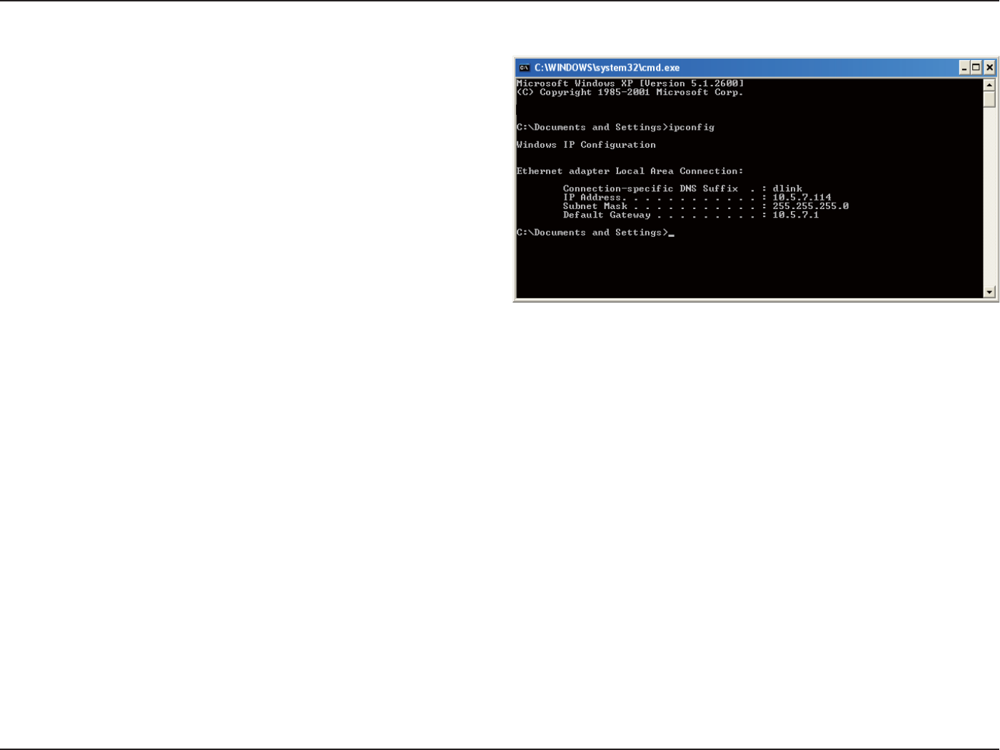
93D-Link DAP-2553 User Manual
Section 6 - Troubleshooting
After you install your network adapter, by default, the TCP/IP settings
should be set to obtain an IP address from a DHCP server (i.e. wireless
router) automatically. To verify your IP address, please follow the steps
below.
Click on Start > Run. In the run box type cmd and click OK.
At the prompt, type ipcong and press Enter.
This will display the IP address, subnet mask, and the default gateway of
your adapter.
If the address is 0.0.0.0, check your adapter installation, security settings,
and the settings on your router. Some rewall software programs may
block a DHCP request on newly installed adapters.
How to check your IP address?
If you are connecting to a wireless network at a hotspot (e.g. hotel, coee shop, airport), please contact an employee or administrator to verify
their wireless network settings.
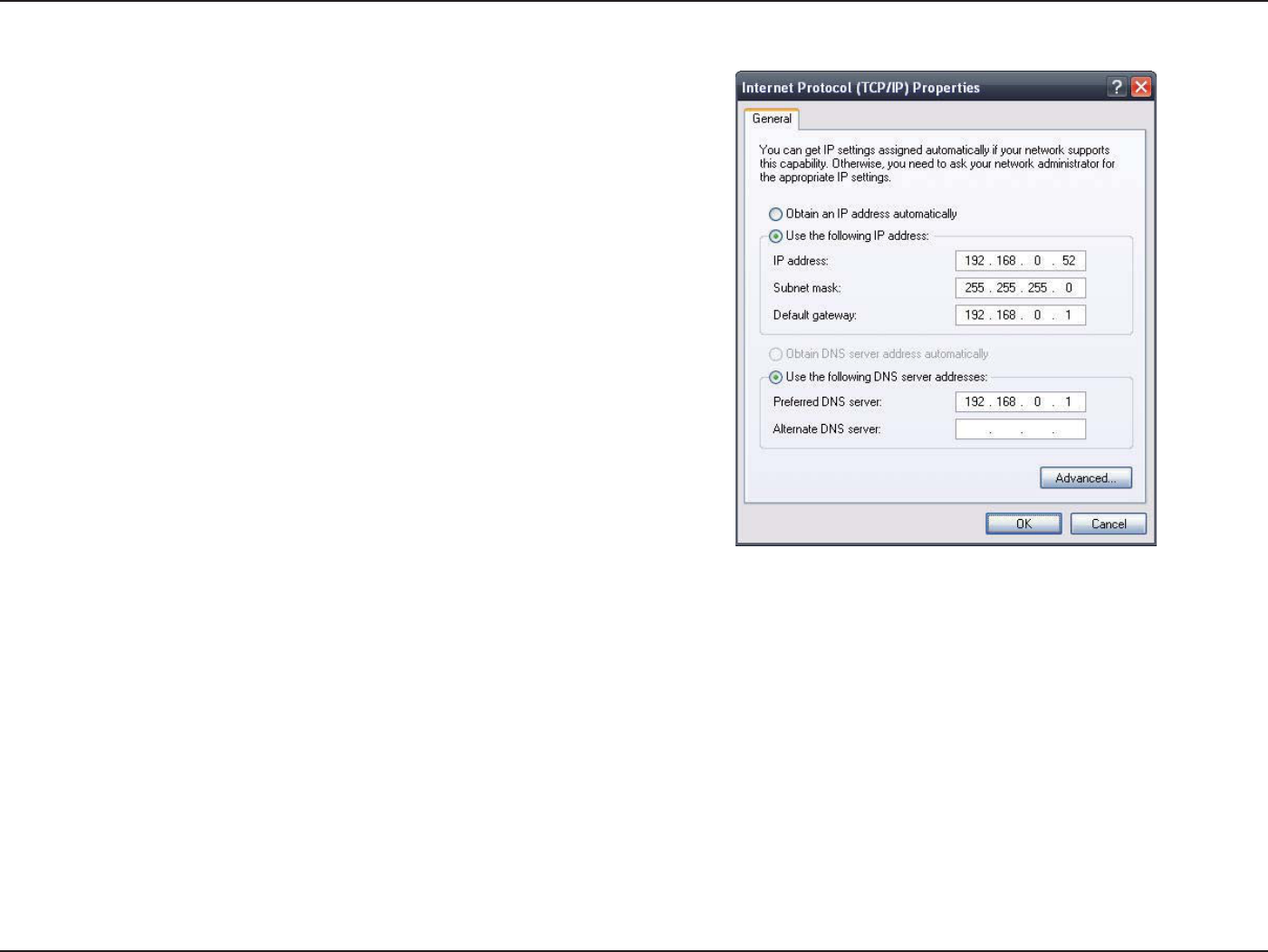
94D-Link DAP-2553 User Manual
Section 6 - Troubleshooting
If you are not using a DHCP capable gateway/router, or you need to
assign a static IP address, please follow the steps below:
Step 1:
Windows® 2000: Click on Start > Settings > Control Panel > Network
Connections
Windows XP: Click on Start > Control Panel > Network Connections
Windows Vista®: Click on Start > Control Panel > Network and Internet >
Network and Sharing Center > Manage network connections
Step 2:
Right-click on the Local Area Connection which represents your network
adapter and select Properties.
Step 3:
Highlight Internet Protocol (TCP/IP) and click Properties.
Step 4:
Click Use the following IP address and enter an IP address that is on the
same subnet as your network or the LAN IP address on your router.
Example: If the router’s LAN IP address is 192.168.0.1, make your IP
address 192.168.0.X where X is a number between 2 and 99. Make sure
that the number you choose is not in use on the network. Set Default
Gateway the same as the LAN IP address of your router (192.168.0.1).
Set Primary DNS the same as the LAN IP address of your router
(192.168.0.1). The Secondary DNS is not needed or you may enter a DNS
server from your ISP.
Step 5:
Click OK twice to save your settings.
How to statically assign an IP address?

95D-Link DAP-2553 User Manual
Appendix C - Technical Specications
Technical Specications
Standards
• IEEE 802.11a
• IEEE 802.11b
• IEEE 802.11g
• IEEE 802.11n
• IEEE 802.3
• IEEE 802.3u
• IEEE 802.3ab
• IEEE 802.3af
Network Management
• Web Browser interface
HTTP
Secure HTTP (HTTPS)
• Central WiFiManager
• SNMP Support
Private MIB
• Command Line Interface
Telnet
Secure SSH Telnet
Data Rates*
For 802.11a:
• 54, 48, 36, 24, 18, 12, 9, and 6 Mbps
For 802.11b:
• 11, 5.5, 2, and 1 Mbps
For 802.11g:
• 54, 48, 36, 24, 18, 12, 9, and 6 Mbps
For 802.11n :
HT20/HT40
• 144.4/300, 130/270, 117/243, 104/216, 78/162, 66/135, 58.5/121.5, 52/108,
39/81, 26/54, 19.5/40.5, 12/27, and 6.5/13.5 Mbps
Security
• WPA™ Personal/Enterprise
• WPA2™ Personal/Enterprise
• WEP™ 64-/128-bit
• SSID Broadcast Disable
• MAC Address Access Control
Wireless Frequency Range
• 2.4 to 2.4835 GHz and 5.15 to 5.85 GHz**
Operating Voltage
• 802.3af PoE or 5V/2A
Radio and Modulation Type
For 802.11a/g/n:
BPSK, QPSK, 16QAM, and 64QAM with OFDM
For 802.11b:
DQPSK, DBPSK, DSSS, and CCK
Operating Frequency**
For 802.11a:
5.15 ~ 5.85 GHz
For 802.11b/g:
2.4 ~ 2.4835 GHz
For 802.11n:
2.4 GHz Band: 2.4 ~ 2.4835 GHz
5 GHz Band: 5.15 ~ 5.85 GHz
Dipole Antenna
• 3dBi Gain @2.4 GHz
• 5dBi Gain @5 GHz
* Maximum wireless signal rate derived from IEEE Standard 802.11g and 802.11n specications. Actual data throughput will vary. Network conditions and environmental factors,
including volume of network trac, building materials and construction, and network overhead, lower actual data throughput rate. Environmental factors will adversely aect
wireless signal range.

96D-Link DAP-2553 User Manual
Appendix C - Technical Specications
Transmit Output Power
• 22.5dBm @ 2.4GHz
• 22.5dBm @ 5GHz
LEDs
• Power
• LAN
• 2.4 GHz
• 5 GHz
Temperature
• Operating: 0˚C to 40˚C
• Storing: -20˚C to 65˚C
Humidity
• Operating: 10%~90% (non-condensing)
• Storing: 5%~95% (non-condensing)
Certications
• FCC
• CE
• CSA
• WiFi
Dimensions
• L = 198 mm
• W = 120 mm
• H = 32 mm
**Please note that operating frequency ranges vary depending on the regulations of individual countries and jurisdictions. The DAP-2553 isn’t supported in the 5.25~5.35 GHz and 5.47 ~ 5.725 GHz frequency ranges in
some regions.

97D-Link DAP-2553 User Manual
Appendix E - Warranty
Warranty
CE Mark Warning:
This is a Class B product. In a domestic environment, this product may cause radio interference, in which case the user may be required to take
adequate measures.
FCC Statement:
This equipment has been tested and found to comply with the limits for a Class B digital device, pursuant to part 15 of the FCC Rules. These limits are
designed to provide reasonable protection against harmful interference in a residential installation. This equipment generates, uses, and can radiate
radio frequency energy and, if not installed and used in accordance with the instructions, may cause harmful interference to radio communication.
However, there is no guarantee that interference will not occur in a particular installation. If this equipment does cause harmful interference to radio
or television reception, which can be determined by turning the equipment o and on, the user is encouraged to try to correct the interference by
one or more of the following measures:
• Reorient or relocate the receiving antenna.
• Increase the separation between the equipment and receiver.
• Connect the equipment into an outlet on a circuit dierent from that to which the receiver is connected.
• Consult the dealer or an experienced radio/TV technician for help.
For detailed warranty information applicable to products purchased outside the United States, please contact the corresponding local
D-Link oce.
FCC Caution:
Any changes or modications not expressly approved by the party responsible for compliance could void the user’s authority to operate this
equipment.
This device complies with Part 15 of the FCC Rules. Operation is subject to the following two conditions:
(1) This device may not cause harmful interference, and
(2) this device must accept any interference received, including interference that may cause undesired operation.
For operation within 5.15 ~ 5.25GHz frequency range, it is restricted to indoor environment. This device meets all the other requirements specied
in Part 15E, Section 15.407 of the FCC Rules.
For operation within 5.15 ~ 5.25GHz
f
requency range, it is restricted to indoor environment. This device meets all the other requirements speci
ed
i
n Part 15E
,
Section 15.407 o
f
the FCC Rules.

98D-Link DAP-2553 User Manual
Appendix E - Warranty
IMPORTANT NOTICE:
FCC Radiation Exposure Statement:
This equipment complies with FCC radiation exposure limits set forth for an uncontrolled environment. This equipment should be installed and
operated with minimum distance 20cm between the radiator & your body. This transmitter must not be co-located or operating in conjunction
with any other antenna or transmitter.
The availability of some specic channels and/or operational frequency bands are country dependent and are rmware programmed at the factory
to match the intended destination. The rmware setting is not accessible by the end user.
For detailed warranty information applicable to products purchased outside the United States, please contact the corresponding local D-Link
oce.
FOR COUNTRY CODE SELECTION USAGE (WLAN DEVICES)
Note: The country code selection is for non-US model only and is not available to all US model. Per FCC regulation, all WiFi product marketed in US
must xed to US operation channels only.
This unit is to be used with a power supply, P/N 2ABE10B US or WB-10E05R or F12W3-050200SPAU.
Cet appareil doit être utilisé avec une source de courrant, modèle 2ABE10B US , WB-10E05R , F12W3-050200SPAU.
F
OR COUNTRY CODE SELECTION USAGE
(
WLAN DEVICES
)
Note: The countr
y
code selection is for non-US model onl
y
and is not available to all US model. Per FCC regulation, all WiFi product marketed in US
must xed to US operation channels onl
y
.