D Link AP2695A1 AirPremier AC Simultaneous Dual Band PoE Access Point User Manual
D Link Corporation AirPremier AC Simultaneous Dual Band PoE Access Point
D Link >
User Manual

2DAP-2695 Install Guide
Minimum System Requirements:
• CD-ROM Drive
• Computers with Windows®, Macintosh®, or Linux-based
operating systems
• Installed Ethernet adapter or wireless adapter
• Internet Explorer 7, Chrome, Firefox, or Safari 4 or higher
System Requirements
Package Contents
Note: Using a power supply with a dierent voltage than the one included with the DAP-2695 will cause damage and
void the warranty for this product. If any of the above items are missing, please contact your reseller.
• DAP-2695 Access Point
• Six Detachable Antennas
• Power Adapter
• Power Cord
• PoE Base Unit
• Mounting Plate and Hardware
• Ethernet Cable
• Console Cable
• CD (with software and user manual)
* Maximum Wireless signal rate derived from IEEE 802.11ac (draft), 802.11n, 802.11a, and 802.11g specications. Actual data
throughput will vary. Network conditions and environmental factors, including volume of network trac, building materi-
als and construction, and network overhead lower actual data throughput rate.
DAP-2695 Install Guide 3
Hardware Overview
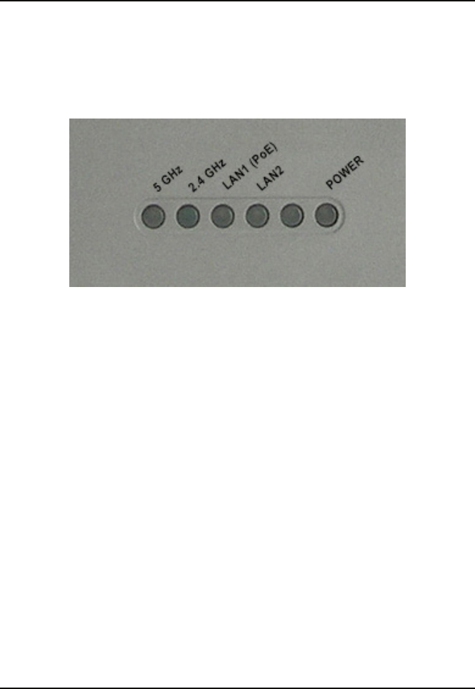
LEDs
5 GHz - When lit, the access point is operating at 5GHz. This light will
blink when there is wireless trac.
2.4 GHz - When lit, the access point is operating at 2.4GHz. This light
will blink when there is wireless trac.
LAN1 (PoE) - Solid light when the Ethernet port is connected to a
power over Ethernet (PoE) port, such as a router or switch. The light will
blink when there is trac through LAN port.
LAN2 - Solid light when the Ethernet port is connected to a working
port, such as a router or switch. The light will blink when there is trac
through LAN port.
POWER - The light will blink during boot up. Once solid, the access
point is ready.
4DAP-2695 Install Guide
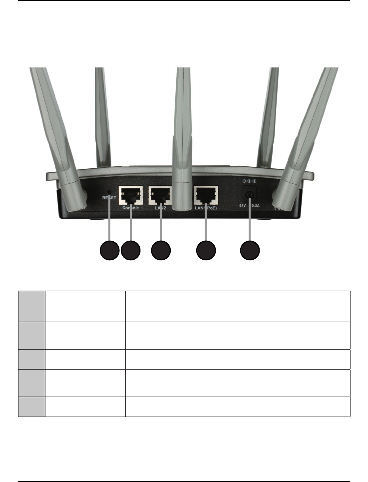
1Reset Button Press and hold for six seconds to reset the access
point to the factory default settings.
2Console Port Connect the supplied console cable to congure
using a command line interface.
3LAN2 Port Connect to your network with an Ethernet cable.
4LAN1 (PoE) Port Connect to a Power over Ethernet (PoE) switch or
router.
5Power Receptor Connect the supplied power adapter.
1 2 3 4 5
Connections
DAP-2695 Install Guide 5
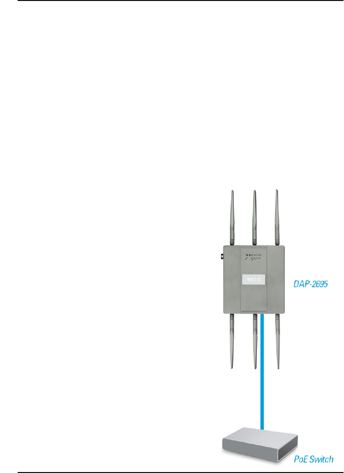
To power the access point, you can use one of the following 3 methods:
Method 1 - Use if you have a PoE switch or router.
Method 2 - Use if you do not have a PoE switch or router and do not
have a power outlet near the location of the access point.
Method 3 - Use if you do not have a PoE switch or router and have a
power outlet near the location of the access point.
Method 1
1. Connect one end of your Ethernet cable to the LAN1 (PoE) port on the access
point.
2. Connect the other end into one port on a PoE switch or router.
Installation
6DAP-2695 Install Guide
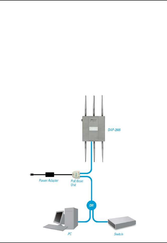
Method 2
1. Connect one end of an Ethernet cable into the Data In port on the PoE base
unit and the other end into one port on your switch, router, or computer.
2. Connect one end of an Ethernet cable into the P+Data Out port on
the PoE base unit and the other end into the LAN1 (PoE) port on the
Access Point.
3. Use the supplied power adapter. Connect the power adapter to the Power In
receptor on the PoE adapter.
4. Connect the power cable to the power adapter and then connect the other end
into a power outlet.
DAP-2695 Install Guide 7
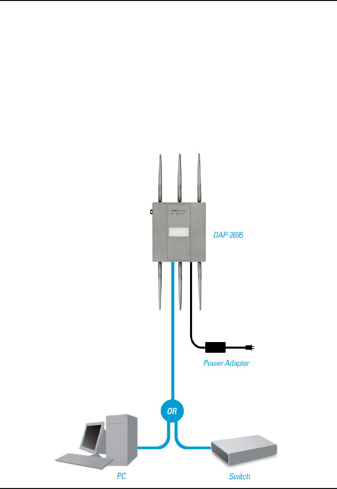
Method 3
1. Connect one end of your Ethernet cable into the LAN2 port on the Access Point
and then connect the other end to a switch, router, or computer.
2. Use the supplied power adapter. Connect the power adapter to the Power
receptor on the Access Point.
3. Connect the power cable to the power adapter and then connect the other end
into a power outlet.
8DAP-2695 Install Guide
Conguration
Note: It is recommended to congure your DAP-2695 before mounting. The easiest way
is to connect to the Access Point directly to a computer using an Ethernet cable. Statically
assign the IP address of your computer to 192.168.0.2 with a subnet mask of 255.255.255.0.
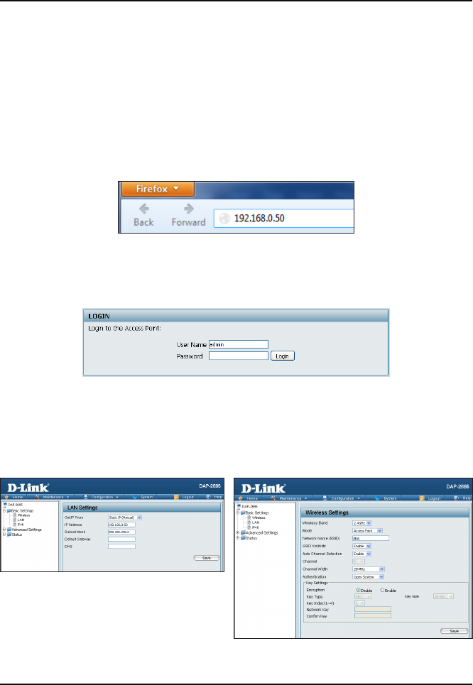
Step 1: Open a web browser (e.g., Internet Explorer, Chrome, Firefox , or Safari) and
enter http://192.168.0.50.
Step 2: At the login screen, enter admin for the user name and leave the password
blanks. Click Login to continue.
Step 3: After the home page appears, go to Basic Settings > LAN to change the IP
settings of the DAP-2695. Go to Basic Settings > Wireless to congure your wireless
settings.
Note: Make sure you click on Conguration > Save and Activate to save your settings.
DAP-2695 Install Guide 9
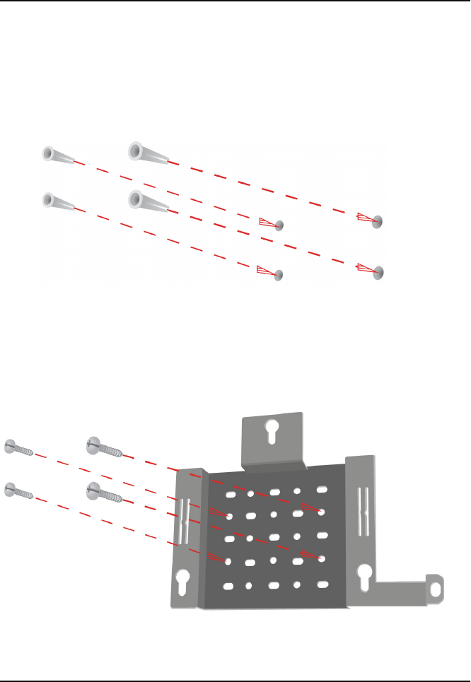
Step 1: Insert the provided wall anchors in the wall where the mounting plate will
be attached.
Mounting
Step 2: Use the provided screws to secure the mounting plate on the wall.
10 DAP-2695 Install Guide
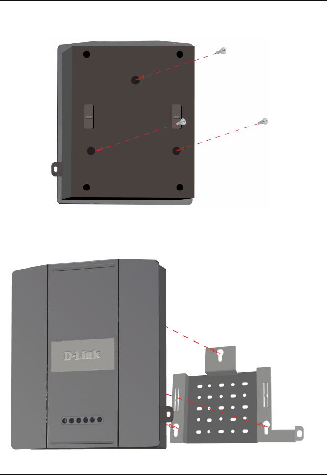
Step 3: Attach the remaining screws securely to the back of the DAP-2695.
Step 4: Attach the DAP-2695 to the mounting plate.

DAP-2695 Install Guide 11
Step 5: Slide the DAP-2695 down into the grooves on the mounting plate to secure
it to the plate.

Technical Support
D-Link’s website contains the latest user documentation and software updates for D-Link
products.
U.S. and Canadian customers can contact D-Link Technical Support through our website
or by phone.
United States
Telephone
(877) 354-6555
World Wide Web
http://support.dlink.com
Canada
Telephone
(877) 354-6560
World Wide Web
http://support.dlink.ca
Version 1.0
July 8, 2013
Copyright ©2013 D-Link Corporation/D-Link Systems, Inc. All rights reserved. D-Link and the D-Link logo are trademarks or registered
trademarks of D-Link Corporation or its subsidiaries in the United States and other countries. Other trademarks are the property of
their respective owners. All references to speed are for comparison purposes only. Product specications, size, and shape are subject
to change without notice, and actual product appearance may dier from that depicted herein. Visit www.dlink.com for more details.
FCC Statement:
Federal Communication Commission Interference Statement
This equipment has been tested and found to comply with the limits for a Class B digital device,
pursuant to Part 15 of the FCC Rules. These limits are designed to provide reasonable protection
against harmful interference in a residential installation. This equipment generates, uses and can
radiate radio frequency energy and, if not installed and used in accordance with the instructions, may
cause harmful interference to radio communications. However, there is no guarantee that interference
will not occur in a particular installation. If this equipment does cause harmful interference to radio or
television reception, which can be determined by turning the equipment off and on, the user is
encouraged to try to correct the interference by one of the following measures:
● Reorient or relocate the receiving antenna.
● Increase the separation between the equipment and receiver.
● Connect the equipment into an outlet on a circuit different from that to which the receiver is
connected.
● Consult the dealer or an experienced radio/TV technician for help.
FCC Caution: Any changes or modifications not expressly approved by the party
responsible for compliance could void the user’s authority to operate this equipment.
This device complies with Part 15 of the FCC Rules. Operation is subject to the following two
conditions: (1) This device may not cause harmful interference, and (2) this device must accept any
interference received, including interference that may cause undesired operation.
For product available in the USA/Canada market, only channel 1~11 can be operated. Selection of
other channels is not possible.
This device and it's antennas(s) must not be co-located or operating in conjunction with any other antenna or
transmitter except in accordance with FCC multi-transmitter product procedures.
This device is going to be operated in 5.15~5.25GHz frequency range, it is restricted in indoor
environment only.
IMPORTANT NOTE:
FCC Radiation Exposure Statement:
This equipment complies with FCC radiation exposure limits set forth for an uncontrolled environment.
This equipment should be installed and operated with minimum distance 20cm between the radiator &
your body.
IC Statement:
CAN ICES-3 (B)/NMB-3(B)
This device complies with Industry Canada license-exempt RSS standard(s). Operation is subject to
the following two conditions: (1) this device may not cause interference, and (2) this device must
accept any interference, including interference that may cause undesired operation of the device.
Le présent appareil est conforme aux CNR d'Industrie Canada applicables aux appareils radio exempts de licence.
L'exploitation est autorisée aux deux conditions suivantes : (1) l'appareil ne doit pas produire de brouillage, et (2)
l'utilisateur de l'appareil doit accepter tout brouillage radioélectrique subi, même si le brouillage est susceptible d'en
compromettre le fonctionnement.
For product available in the USA/Canada market, only channel 1~11 can be operated. Selection of
other channels is not possible.
Pour les produits disponibles aux États-Unis / Canada du marché, seul le canal 1 à 11 peuvent être exploités. Sélection
d'autres canaux n'est pas possible.
This device and it's antennas(s) must not be co-located or operating in conjunction with any other antenna or
transmitter except in accordance with IC multi-transmitter product procedures.
Cet appareil et son antenne (s) ne doit pas être co-localisés ou fonctionnement en association avec une autre antenne ou
transmetteur.
The device could automatically discontinue transmission in case of absence of information to transmit,
or operational failure. Note that this is not intended to prohibit transmission of control or signaling
information or the use of repetitive codes where required by the technology.
Le dispositif pourrait automatiquement cesser d'émettre en cas d'absence d'informations à transmettre, ou une défaillance
opérationnelle. Notez que ce n'est pas l'intention d'interdire la transmission des informations de contrôle ou de
signalisation ou l'utilisation de codes répétitifs lorsque requis par la technologie.
The device for the band 5150-5250 MHz is only for indoor usage to reduce potential for harmful
interference to co-channel mobile satellite systems.
les dispositifs fonctionnant dans la bande 5150-5250 MHz sont réservés uniquement pour une
utilisation à l’intérieur afin de réduire les risques de brouillage préjudiciable aux systèmes de satellites mobiles utilisant
les mêmes canaux;
IMPORTANT NOTE:
IC Radiation Exposure Statement:
This equipment complies with IC RSS-102 radiation exposure limits set forth for an uncontrolled
environment. This equipment should be installed and operated with minimum distance 20cm between
the radiator & your body.
Cet équipement est conforme aux limites d'exposition aux rayonnements IC établies pour un environnement non contrôlé.
Cet équipement doit être installé et utilisé avec un minimum de 20 cm de distance entre la source de rayonnement et votre
corps.