D Link CS5222LB1 HD Wireless N Pan/Tilt Network Camera User Manual
D Link Corporation HD Wireless N Pan/Tilt Network Camera
D Link >
User manual
HD Wireless N Pan/Tilt Network Camera
User Manual
DCS-5222LB1

iD-Link DCS-5222LB1 User Manual
Manual Overview
D-Link reserves the right to revise this publication and to make changes in the content hereof without obligation to notify any
person or organization of such revisions or changes. Information in this document may become obsolete as our services and
websites develop and change. Please refer to the www.mydlink.com website for the most current information.
Manual Revisions
Trademarks
D-Link and the D-Link logo are trademarks or registered trademarks of D-Link Corporation or its subsidiaries in the United
States or other countries. All other company or product names mentioned herein are trademarks or registered trademarks of
their respective companies.
Copyright © 2013 by D-Link Corporation.
All rights reserved. This publication may not be reproduced, in whole or in part, without prior expressed written permission
from D-Link Corporation.
Revision Date Description
1.0 11/311/2013 DCS-5222LB1 Revision B1 with rmware version 1.00
Manual Overview

iiD-Link DCS-5222LB1 User Manual
Table of Contents
Product Overview ..............................................................1
Package Contents ......................................................................... 1
System Requirements .................................................................2
Introduction ................................................................................... 3
Features ............................................................................................ 4
Hardware Overview ..................................................................... 5
Front .......................................................................................... 5
LEDs ........................................................................................... 6
Back............................................................................................ 7
Left and Right Side ...............................................................8
Adjusting Camera Focus ............................................................ 9
Installation .......................................................................10
Zero Conguration Setup ........................................................11
Camera Setup Wizard ................................................................14
Wireless Installation Considerations ....................................17
WPS - Push Button Setup .........................................................18
mydlink .............................................................................19
Conguration ...................................................................21
Conguration Utility ..................................................................21
Live Video ......................................................................................22
Setup ...............................................................................................24
Setup Wizard ........................................................................24
Internet Connection Setup Wizard ..........................25
Motion Detection Setup Wizard ...............................29
Network ..................................................................................33
Wireless ..................................................................................36
Dynamic DNS .......................................................................37
Image Setup .........................................................................38
Audio and Video ..................................................................40
PTZ ...........................................................................................42
Motion Detection ...............................................................43
Sound Detection .................................................................44
Time and Date ......................................................................45
SD Management .................................................................55
Maintenance ................................................................................56
Admin .....................................................................................56
System ....................................................................................58
Firmware Upgrade ..............................................................59
Status ..............................................................................................60
Device Info ............................................................................60
Log ...........................................................................................61
Help .................................................................................................62
Conguring the DCS-5222LB1 with a Router ................63
Troubleshooting ..............................................................69
Networking Basics ...........................................................73
Check your IP address ...............................................................73
Statically Assign an IP Address ..............................................74
Table of Contents

iiiD-Link DCS-5222LB1 User Manual
Table of Contents
Technical Specications - I/O Terminal Applications ....75
Technical Specications ..................................................76

1D-Link DCS-5222LB1 User Manual
Section 1 - Product Overview
Package Contents
1 Using a power supply with a dierent voltage rating than the one included with the DCS-5222LB1 will cause damage and
void the warranty for this product. If any of the above items are missing from your package, please contact your retailer.
DCS-5222LB1 Network Camera
Camera Base and Mounting Kit
CAT5 Ethernet Cable
Product Overview
Power Supply1
CD-ROM

2D-Link DCS-5222LB1 User Manual
Section 1 - Product Overview
System Requirements
Network Requirements • 10/100 Ethernet network or an 802.11n/g/b wireless network
CD Setup Wizard Requirements
• An Internet connection
• A router connected to your broadband modem
Computer with the following:
• A PC with a wired connection to your router
• Windows® 8 (32/64bit), Windows® 7 (32/64bit), XP (32/64bit),Vista® (32/64bit),
Mac OS®X 10.5 or above
Web-based Conguration Utility
Requirements
Browser Requirements:
• Internet Explorer 8 or higher
• Firefox 12 or higher
• Safari 4 or higher
• Chrome 20 or higher
Note: Make sure you have the latest version of Java installed.
Visit www.java.com to download the latest version.
mydlink Website Requirements
• Broadband Internet connection
• Computer with:
• Internet Explorer 7 or higher (ActiveX)
• Firefox 12 or higher
• Safari 4 or higher
• Chrome 20 or higher

3D-Link DCS-5222LB1 User Manual
Section 1 - Product Overview
Congratulations on your purchase of the DCS-5222LB1 HD Wireless N Pan/Tilt Network Camera. The DCS-5222LB1 is a versatile
solution for your small oce or home. The DCS-5222LB1 is a complete system with a built-in CPU and web server that transmits
high quality video images for security and surveillance. It can be accessed remotely, and controlled from any PC/Notebook over
your local network or across the Internet via a web browser. The DCS-5222LB1 features 802.11n wireless connectivity, allowing
the camera to be placed anywhere within range of your wireless network. The DCS-5222LB1 comes with remote monitoring
and motion detection features for a complete and cost-eective home security solution.
Introduction

4D-Link DCS-5222LB1 User Manual
Section 1 - Product Overview
Simple to Use
The DCS-5222LB1 is a stand-alone system with a built-in CPU, requiring no special hardware or software such as PC frame grabber cards. The
DCS-5222LB1 supports both ActiveX mode for Internet Explorer and Java mode for other browsers such as Firefox, Chrome, and Safari.
Supports a Variety of Platforms
The DCS-5222LB1 supports TCP/IP networking, HTTP, and other Internet related protocols. It can also be integrated easily into other Internet/Intranet
applications because of its standards-based features.
Web Conguration
Using a standard web browser, administrators can congure and manage the network camera directly from its own web page via an Intranet or
the Internet.
Broad Range of Applications
With today’s high-speed Internet services, the DCS-5222LB1 network camera can provide an ideal solution for live video over the Internet and for
remote monitoring. The DCS-5222LB1 allows remote access from a web browser for live image viewing and management of the network cameras
anytime, from anywhere in the world. The network camera has a wide range of applications, including industrial and public monitoring of homes,
oces, banks, hospitals, child-care centers, and amusement parks.
802.11n Wireless or Ethernet/Fast Ethernet Support
The DCS-5222LB1 oers wireless 802.11n and Ethernet/Fast Ethernet connectivity, making the DCS-5222LB1 easy to integrate into your existing
network environment. The DCS-5222LB1 works with a 10Mbps Ethernet based network or 100Mbps Fast Ethernet based network for traditional
wired environments, and works with 802.11n routers or access points for added exibility. The Site Survey feature also allows you to view and
connect to any available wireless networks.
Remote Monitoring Utility
The D-ViewCam application adds enhanced features and functionality for the network camera and allows administrators to congure and access
the network camera from a remote site via Intranet or Internet. Other features include image monitoring, recording images to a hard drive, viewing
up to 32 cameras on one screen, and taking snapshots. Note that D-ViewCam works on Windows® computers only.
IR LED for day and night functionality
The built-in infrared LEDs enables night time viewing of up to 16 feet (5 meters).
Features
5D-Link DCS-5222LB1 User Manual
Section 1 - Product Overview
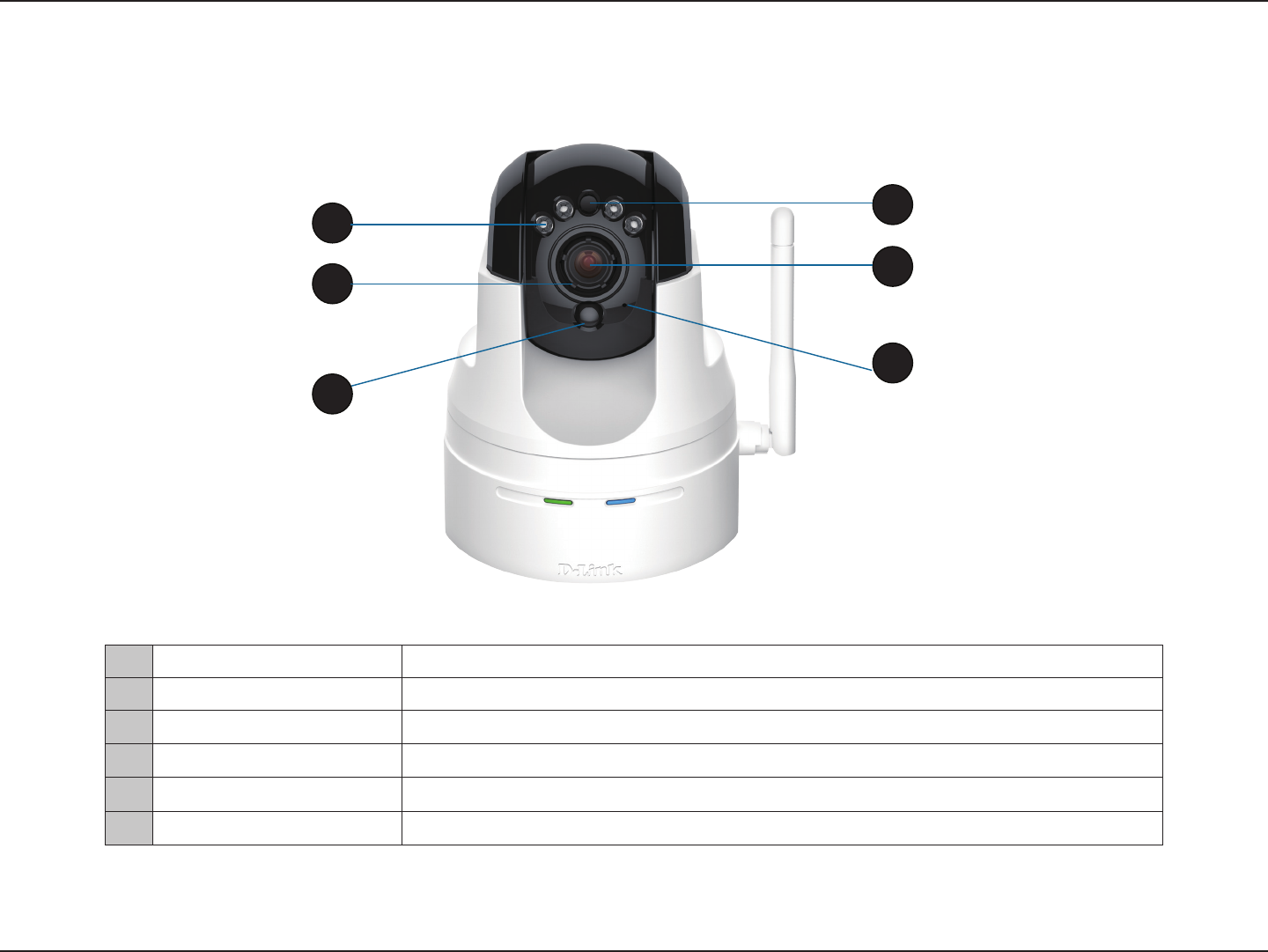
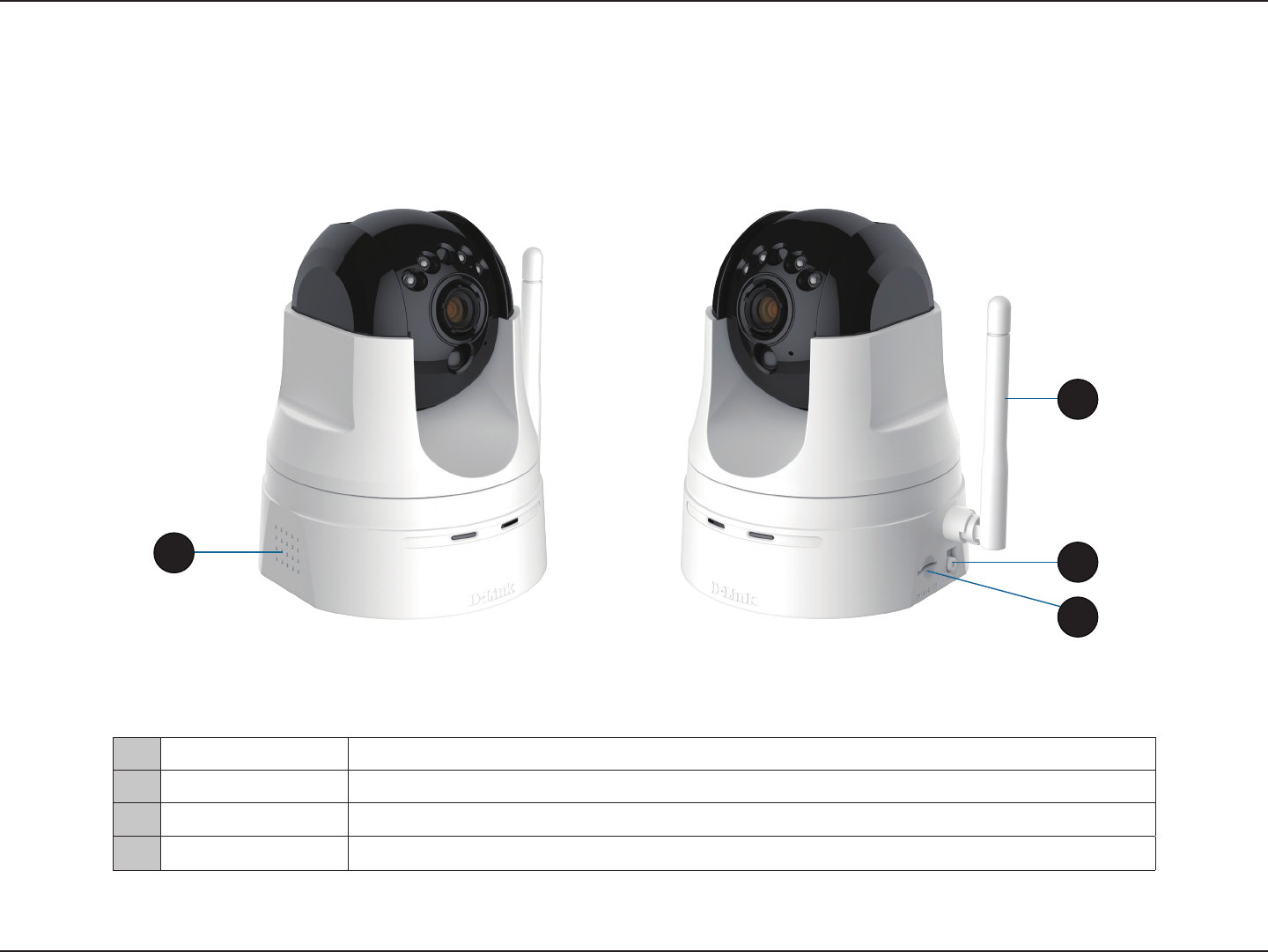
Hardware Overview
Front
1
2
4
5
8
6
1 IR LEDs for night vision Used to illuminate the camera’s eld of view at night
2 Focus Adjustment Ring Enables manual adjustment of the cameras focal length.
3 Passive Infrared Sensor Passive Infrared (PIR) sensor for motion detection
4 Light Sensor Detects light levels and adjusts IR-LEDS accordingly.
5 Camera Lens Records video of the surrounding area
6 Microphone Records audio from the surrounding area
3
6D-Link DCS-5222LB1 User Manual
Section 1 - Product Overview
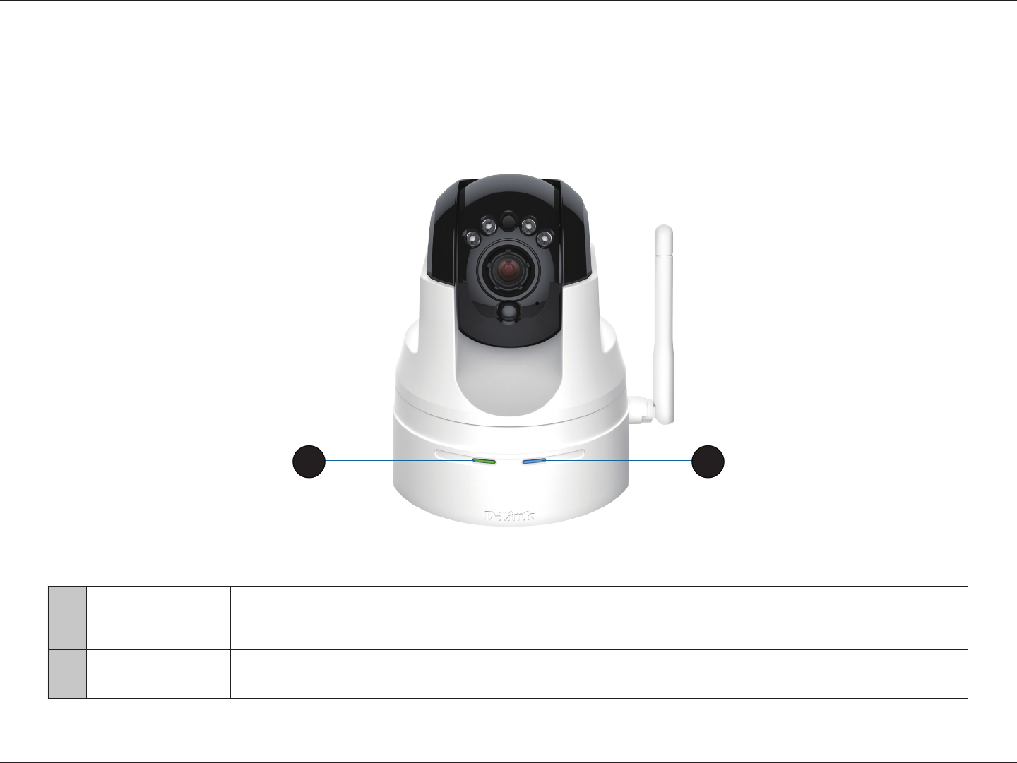
1 Power & Link LED
The LED will be solid red while the camera boots, performs a self test, and searches for a network
connection. The LED will switch to solid green when a proper connection has been achieved. The LED
will blink green during data transfer. .
2 WPS Status LED Indicates the WPS (Wi-Fi Protected Setup) connection status of the camera
Hardware Overview
LEDs
21
7D-Link DCS-5222LB1 User Manual
Section 1 - Product Overview
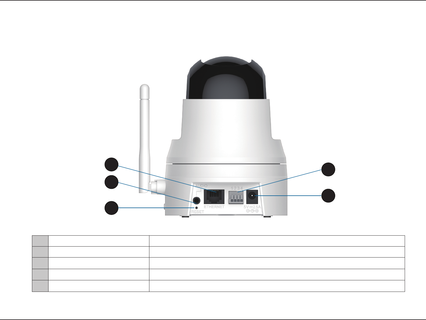
Hardware Overview
Back
1 Ethernet Port Connect 10/100 Ethernet devices such as computers, switches, and hubs.
2 Audio Out Connect headphones/speakers to provide audio out.
3 Reset Button Press the reset button to return the device back to it’s factory conditions.
4 DI/DO Attach digital I/O devices such as alarms or motion sensors.
5 Power Receptor Connects to the power adapter.
1
2
3
4
5
8D-Link DCS-5222LB1 User Manual
Appendix A - Technical Specications
Hardware Overview
Left and Right Side
1 Built in Speaker Use the built-in speaker to provide immediate feedback to triggered events.
2 Antenna The external antenna increases the device’s range of connectivity.
3 WPS Button Use WPS (Wi-Fi Protected Setup) to easily create a secure connection to your network.
4 microSD Slot Insert a microSD card to store recorded images and video.
1
2
3
4
9D-Link DCS-5222LB1 User Manual
Section 1 - Product Overview
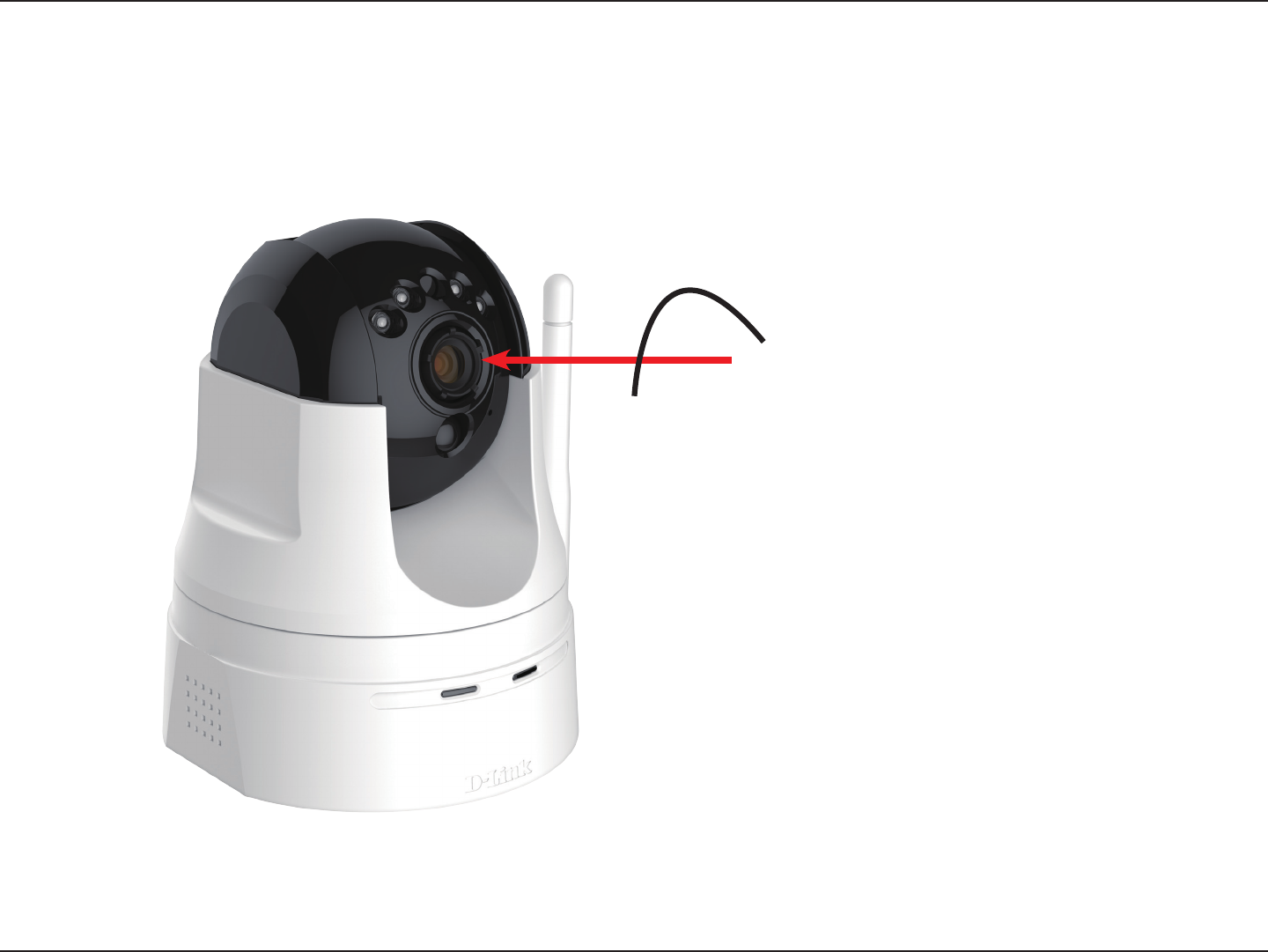
Adjusting Camera Focus
To manually adjust the camera focus, rotate the focussing ring around the lens clockwise or anti-clockwise.

10D-Link DCS-5222LB1 User Manual
Section 1 - Product Overview
There are three ways to set up your camera:
• Zero Conguration Setup: If you have a mydlink-enabled router, this is the easiest way to set up your camera.
Refer to page 11.
• Camera Setup Wizard: If you do not have a mydlink-enabled router, use the Camera Installation Wizard to guide
you through setup and initial conguration of your camera. Refer to page 14.
• Manual Hardware Installation: This section shows you how to manually set up your camera, though in order to
use the mydlink features of your camera, you will still need to run the Camera Installation Wizard. Refer to page 16.
Installation
11D-Link DCS-5222LB1 User Manual
Section 1 - Product Overview
If you have a mydlink-enabled Cloud Router, you can take advantage of Zero Conguration. Zero Conguration automatically
congures your camera's settings for you, and adds it to your mydlink account automatically. This type of setup allows you to
set up your camera by simply plugging it in and connecting it to your router.
Connect your camera to your mydlink-enabled Cloud Router and Zero Conguration will automatically congure your
DCS-5222LB1 and automatically add the camera to your mydlink account. After the short time it takes to do this you can
remotely access your camera from the www.mydlink.com website to manage and monitor your DCS-5222LB1
Zero Conguration Setup
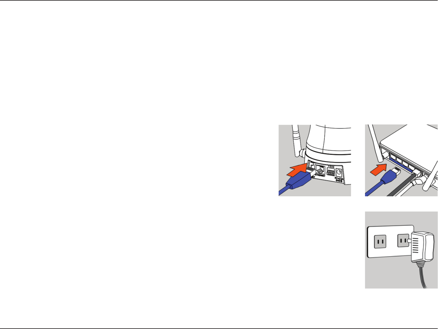
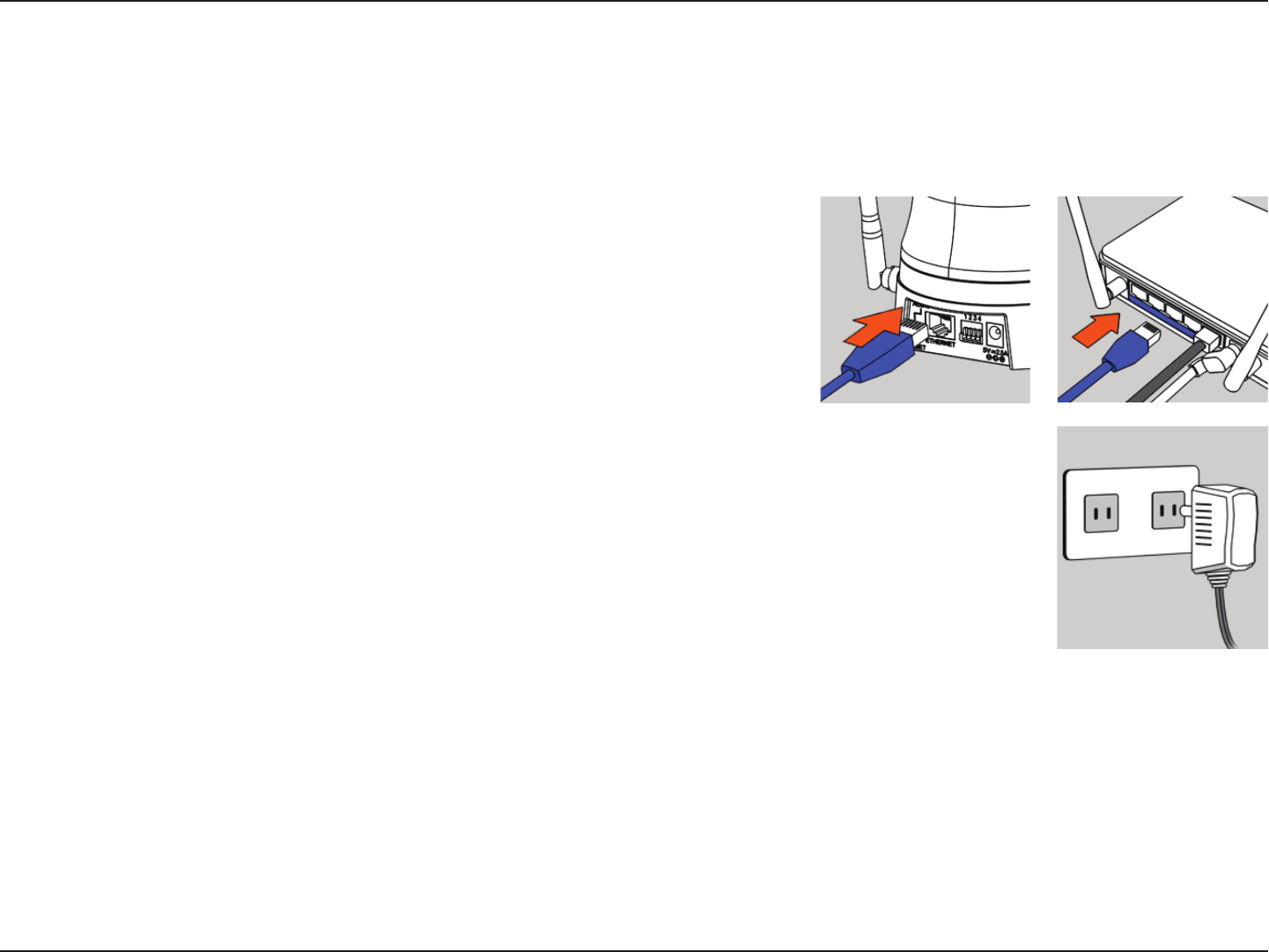
Connect the Ethernet Cable
Use the included Ethernet cable and plug it into the camera. Plug the other
end into an available port on your router. If you wish to use your camera
wirelessly, you will be able to remove the cable after Zero Conguration
Setup is complete.
Attach the External Power Adapter
Connect the power adapter to the power connector on your camera, then
plug the power adapter into a wall outlet.
12D-Link DCS-5222LB1 User Manual
Section 1 - Product Overview
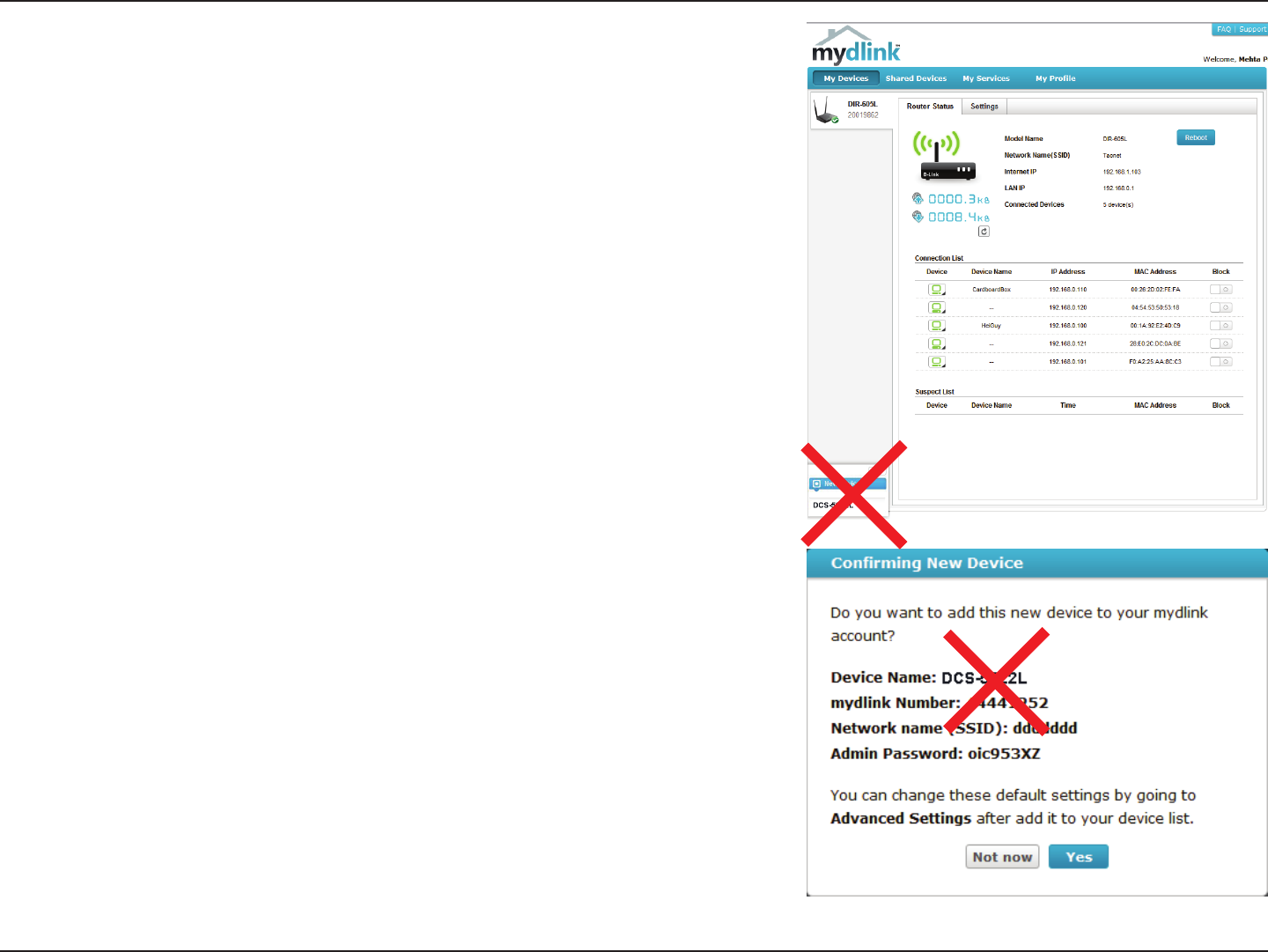
A summary and conrmation notication will appear with the automatically
congured details. Make a note of the details and click Yes to add the camera
to your account.
Check Your mydlink Account
Open a web browser and login to your mydlink account. The mydlink page will
check for new devices and display a New device Found! pop-up notication
in the bottom-left corner. Click the notication to continue.
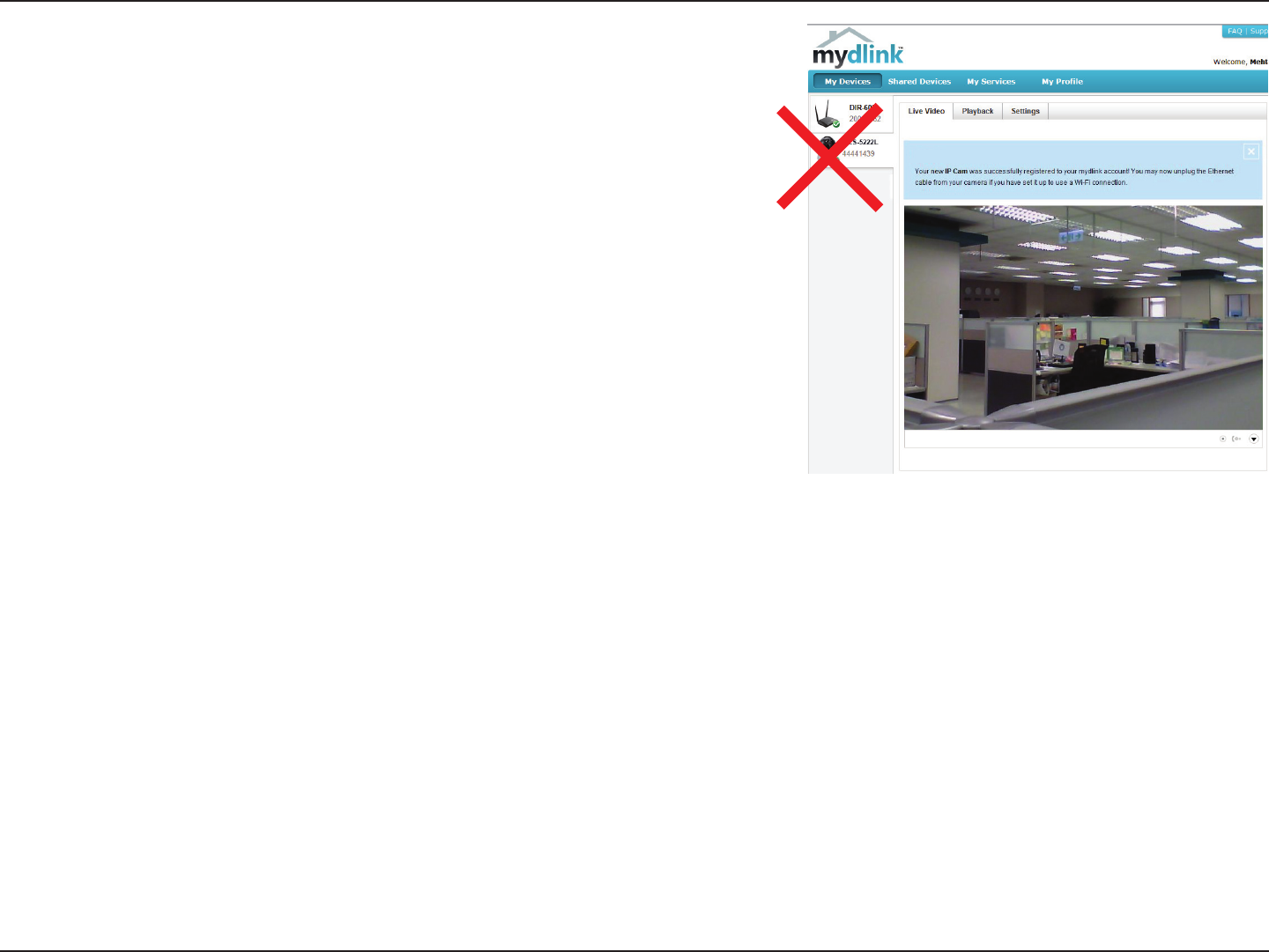
13D-Link DCS-5222LB1 User Manual
Section 1 - Product Overview
Zero Conguration will navigate to the mydlink Live View tab for your camera
where you will see a screen similar to the following.
If you wish to connect your camera to your router wirelessly, you can simply
disconnect the Ethernet cable and move the camera to its intended location;
your router's wireless settings have been automatically transferred to the
camera, and no further conguration is required.
Your camera is now set up, and you can skip to “mydlink” on page 19 to learn
more about the mydlink features of this camera, or to “Conguration” on
page 21 for advanced conguration of your camera.
14D-Link DCS-5222LB1 User Manual
Section 2 - Installation
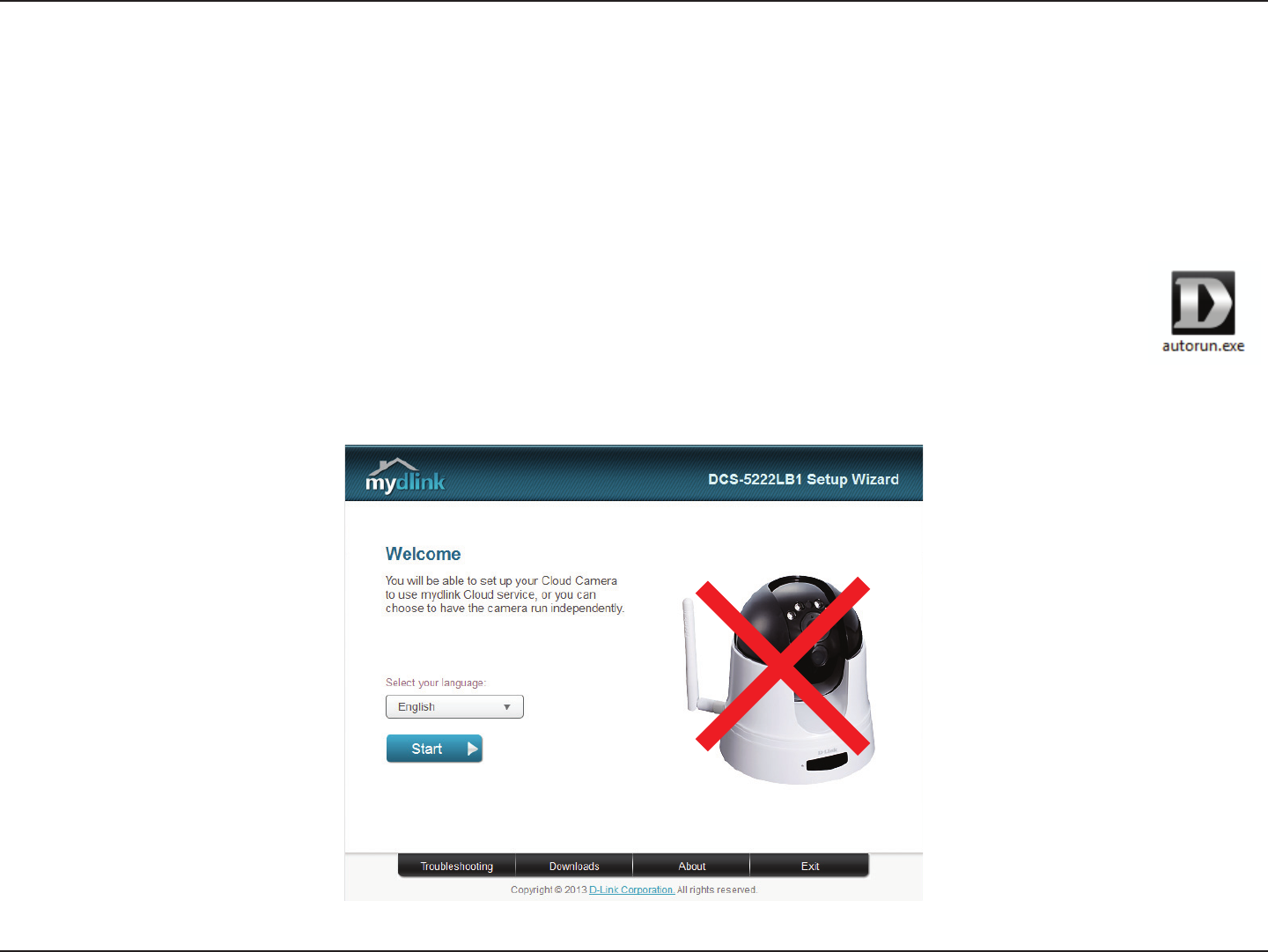
Camera Setup Wizard
Insert the Installation CD-ROM into your computer’s optical drive to start the autorun program. If the autorun
program does not open, go to My Computer, browse to your CD drive, and double-click on the autorun.exe le.
Once the wizard has started simply click Set up your Cloud Camera to go through the Setup Wizard, which will
guide you step-by-step through the installation process from connecting your hardware to conguring your
camera and registering it with your mydlink account.
If you do not have a mydlink-enabled Cloud Router, you can use the Camera Setup Wizard to guide you through the process
of adding your camera to the mydlink service.
Windows Users
15D-Link DCS-5222LB1 User Manual
Section 2 - Installation
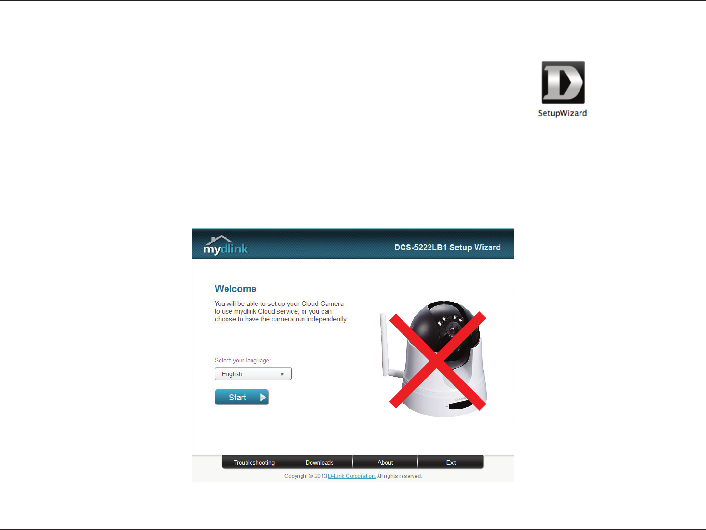
Mac Users
Insert the Installation CD-ROM into your computer’s optical drive. On the desktop, open your
CD drive and double-click on the SetupWizard le.
After about 20-30 seconds, the Setup Wizard will open, which will guide you step-by-step through the installation process
from connecting your hardware to conguring your camera and registering it with your mydlink account.
16D-Link DCS-5222LB1 User Manual
Section 2 - Installation
Manual Hardware Installation
If you wish to set up your camera without using the Camera Setup Wizard, please follow these steps.
Note: In order to use the mydlink features of this product, you will need to go through the Camera Setup Wizard or Zero
Conguration Setup.
Optional: Use WPS to Connect Wirelessly
You can use WPS to connect your camera to your network wirelessly. For
more information, refer to “WPS - Push Button Setup” on page 18. If your router
does not support WPS, you will still be able to set up your camera’s wireless
settings in the camera’s web interface.
Connect the Ethernet Cable and Power Cable
Use the included Ethernet cable and plug it into the camera. Plug the other
end into an available LAN port on your router. Plug the supplied power
adapter into the back of the camera
Plug in the External Power Adapter
Plug the power adapter into a wall outlet.
Congure Your Camera
Refer to “Conguration” on page 21 for information on how to congure your
camera.

17D-Link DCS-5222LB1 User Manual
Section 1 - Product Overview
Wireless Installation Considerations
The D-Link Wireless Network Camera lets you access your network using a wireless connection from anywhere within the operating range of your
wireless network. However, the number, thickness and location of walls, ceilings, or other objects that the wireless signals must pass through, may
limit the range. Typical ranges vary depending on the types of materials and background RF (radio frequency) noise in your home or business.
The key to maximizing wireless range is to follow these basic guidelines:
1. Minimize the number of walls and ceilings between your adapter and other network devices (such as your network camera) -
each wall or ceiling can reduce your adapter’s range from 3-90 feet (1-30 meters).
2. Be aware of the direct line between network devices. A wall that is 1.5 feet thick (.5 meters), at a 45-degree angle appears to be
almost 3 feet (1 meter) thick. At a 2-degree angle, it looks over 42 feet (14 meters) thick. Position your devices so that the signal
will travel straight through a wall or ceiling (instead of at an angle) for better reception.
3. Building materials make a dierence. A solid metal door or aluminum studs may weaken the wireless signal. Try to position
your access points, wireless routers, and other networking devices where the signal passes through drywall or open doorways.
Materials and objects such as glass, steel, metal, walls with insulation, water (sh tanks), mirrors, le cabinets, brick, and concrete
will degrade your wireless signal.
4. Keep your product at least 3-6 feet or 1-2 meters away from electrical devices or appliances that generate RF noise.
5. If you are using 2.4GHz cordless phones or other radio frequency sources (such as microwave ovens), your wireless connection
may degrade dramatically or drop completely. Make sure your 2.4GHz phone base is as far away from your wireless devices as
possible. The base transmits a signal even if the phone in not in use.

18D-Link DCS-5222LB1 User Manual
Section 2 - Installation
To create a WPS connection:
Step 1
Press and hold the WPS button for three seconds. The blue WPS status LED above
the button will blink.
Step 2
Press the WPS button on your router or access point within 120 seconds. The WPS
button is usually on the front or side of your router. On some routers and access
points, you may need to log in to the web interface and click on an on-screen
button to activate the WPS feature. If you are not sure where the WPS button is
on your router/AP, please refer to your router or AP’s User Manual.
The DCS-5222LB1 will automatically create a wireless connection to your router
or access point. While connecting, the green LED will ash and your camera will
reboot.
WPS - Push Button Setup
Alternatively, you may create a connection to the camera using the Wi-Fi Protected Setup (WPS) feature.
WPS Button
19D-Link DCS-5222LB1 User Manual
Section 3 - mydlink Portal
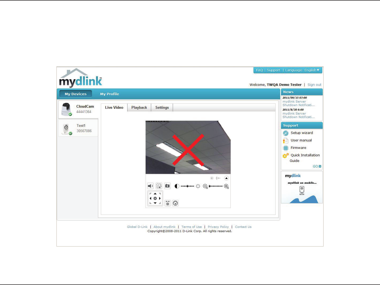
mydlink
After registering your DCS-5222LB1 camera with a mydlink account in the Camera Setup Wizard. You will be able to remotely
access your camera from the www.mydlink.com website. After signing in to your mydlink account, you will see a screen similar
to the following:
For more details on using your camera with mydlink, go to the Support section of the mydlink website and check the User
Manual section for your product to nd the latest instruction guide for your camera's mydlink features.

20D-Link DCS-5222LB1 User Manual
Section 3: mydlink
Camera Status
If your camera is oine, try the following:
• Check to make sure that the Internet connection to your camera is working properly.
• Try restarting your Internet router.
• Check your camera’s cable connections and make sure they are secure.
• Check to make sure that the LED on your camera is lit solid green.
If you still cannot access your camera, reset your camera and run the Camera Installation Wizard again from the CD-ROM
included in your package.
Here, you can see the online status of each of your cameras. Your online status may be one of the following:
A red X indicates that your camera is oine and currently cannot be accessed remotely.
A green checkmark indicates that your camera is online and ready to use.
A yellow exclamation point indicates that your camera is online, but the camera password
has changed. You will need to enter your new camera password to access your camera
again.
21D-Link DCS-5222LB1 User Manual
Section 4 - Conguration
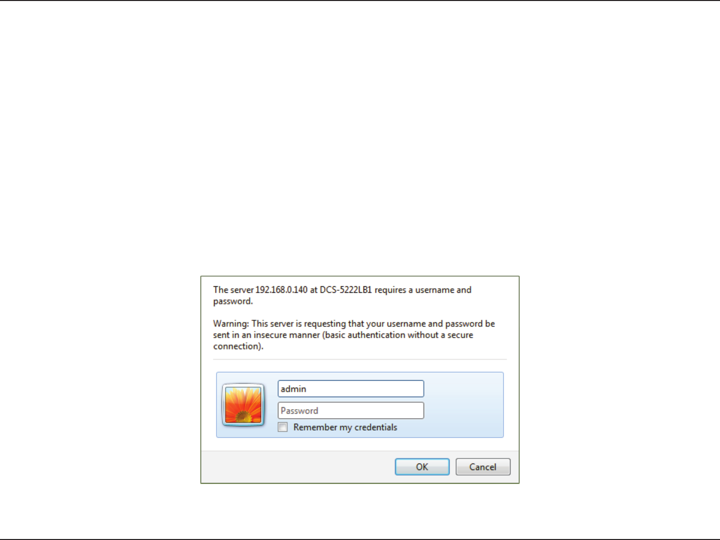
Conguration
After completing the Camera Installation Wizard, you are ready to use your camera. The camera’s built-in Web conguration
interface is designed to allow you to easily access and congure your DCS-5222LB1. At the end of the wizard, enter the IP
address of your camera into a web browser, such as Internet Explorer®. To log in, use the User name admin and the password
you created in the Installation Wizard. If you did not create a password, the default password is blank. After entering your
password, click OK.
Note: If you are directly connecting your PC to the camera, or if you are using the camera on a closed network, the default IP
is 192.168.0.20.
Conguration Utility
22D-Link DCS-5222LB1 User Manual
Section 4 - Conguration
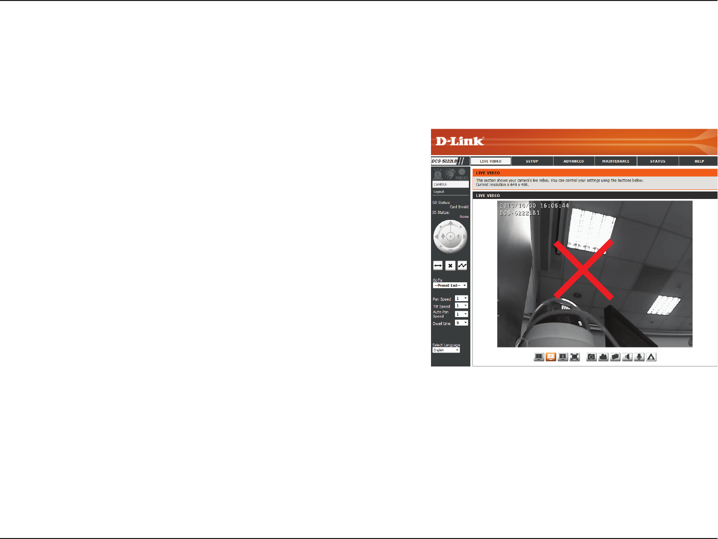
Live Video
Please make sure that you have the latest version of Java installed on your computer to ensure proper operation when viewing
the video in Java mode. Java can be downloaded free from Sun’s web site (http://www.java.com).
A live feed from the camera is displayed upon logging into the camera’s web interface.
Use the Pan / Tilt / Zoom action pad to control the camera’s movement
and zoom. The large arrow icons will move the camera up, down, left
or right while the small arrow icons will move the camera position
diagonally in the direction they are pointed. The Home button will move
the camera to the preset “Home” position.
Press this button and the camera will pan from left-most position to the
right-most position and then return to its original position.
Click this button to quickly move the camera to the desired patrol setup
according to preset positions. Please refer to 第 42 第第第PTZ第 to create preset
positions.
This will stop pan and patrol.
Select from the preset drop-down list to quickly move the camera to
the desired preset position. Please refer to 第 42 第第第PTZ第 to create preset
positions.
This setting can change the camera’s pan/tilt speed.
Select the default language for the user interface.
The next page contains several icons which can be used to control the
camera’s main functions.
P/T/Z Action Pad:
Pan:
Preset Sequence:
Stop:
Go To:
Pan/Tilt Speed:
Language
Selection:
23D-Link DCS-5222LB1 User Manual
Section 4 - Conguration
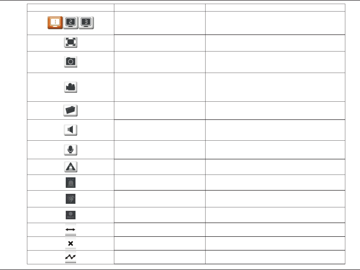
Icon Button Name Function
Prole buttons
Use these buttons to switch between video
proles. Refer to 第 40 第第第Audio and Video第 for
more information on setting up proles.
Full Screen button Displays the video at full screen.
Snapshot button
Takes a snapshot of the image currently displayed on
the screen and will save it to a le on the hard drive in
a folder specied using the Storage folder button.
Video recording button
Triggers the camera’s recording function. This
will record the video displayed on the screen and
will save it to a le on the hard drive in a folder
specied using the Storage folder button.
Storage folder button Sets the location to save snapshots and video recordings.
Listen button Sends the audio received from the camera’s microphone
through to the PC’s speakers. Click again to turn o.
Talk button Sends audio from a microphone connected to your PC
through to the speakers connected to the camera.
Start Digital Input
Digital Input Indicator This indicator will change color when a digital input signal is
detected.
Motion Trigger Indicator This indicator will change color when a motion trigger event
occurs if enabled.
Recording Indicator When a recording is in progress, this indicator will change
color.
Auto Pan Starts the automatic panning function. The ROI will pan
from back and forth within the FOV
Stop Stops automatic panning.
Preset Path Starts the camera's motion along the predened path.
24D-Link DCS-5222LB1 User Manual
Section 4 - Conguration
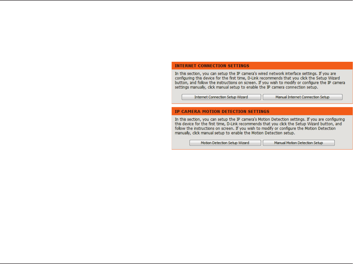
Setup
Setup Wizard
You may choose to congure your network by
using the Internet Connection Setup Wizard
that includes step-by-step instructions. Please
refer to page “Internet Connection Setup
Wizard” on page 25 for more details.
If you would rather manually setup the camera
internet connection, you can refer to 第 33 第第
第Network第 which provides more details on the
information required.
You may choose to congure motion detection
by using the Motion Detection Setup Wizard
that includes step-by-step instructions. Please
refer to page “Motion Detection Setup Wizard”
on page 29 for more details.
If you would rather manually setup the camera’s
motion detection features, you can refer to
page “Motion Detection” on page 43 which
provides more details on the information
required.
Internet
Connection
Setup Wizard:
Manual
Internet
Connection
Setup:
Motion
Detection
Setup Wizard:
Manual
Motion
Detection
Setup:
This section allows you to begin setup wizards which will guide you through the process of getting your camera’s various functions congured. If
you comfortable with adjusting the settings manually, you may skip the wizards and adjust the necessary as needed.
25D-Link DCS-5222LB1 User Manual
Section 4 - Conguration
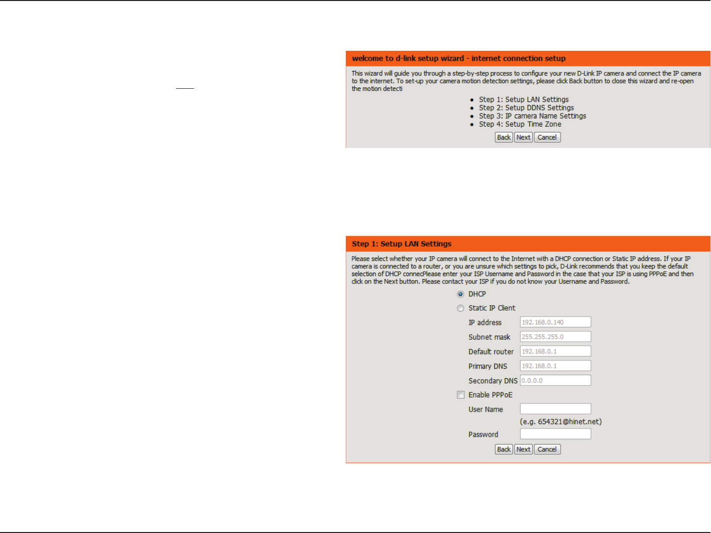
Internet Connection Setup Wizard
This wizard will guide you through a step-by-step process to
congure your new D-Link Camera and connect the camera to the
Internet. Note that this wizard will not register your camera with
mydlink.com.
Click Next to continue.
Select Automatic IP Address if you want your DHCP server (usually
enabled on your router) to assign the camera its IP settings. If you
want to manually assign the IP settings, select Static IP Address and
enter the following details:
Enter an IP address for your camera.
Enter the subnet mask of your network.
Enter the default gateway address. This is
usually the IP address of your router.
Enter the primary DNS server’s IP address. This
is usually the IP address of your router.
Enter the secondary DNS server’s IP address.
This is optional.
If you are required to connect using PPPoE,
select Enabled and enter the Username and
Password for your PPPoE connection. Only select
this option if your camera is directly connected
to your broadband modem. If it is on a network
with a router or gateway, do not select this
option.
Click Next to continue.
IP Address:
Subnet Mask:
Default Gateway:
Primary DNS:
Secondary DNS:
26D-Link DCS-5222LB1 User Manual
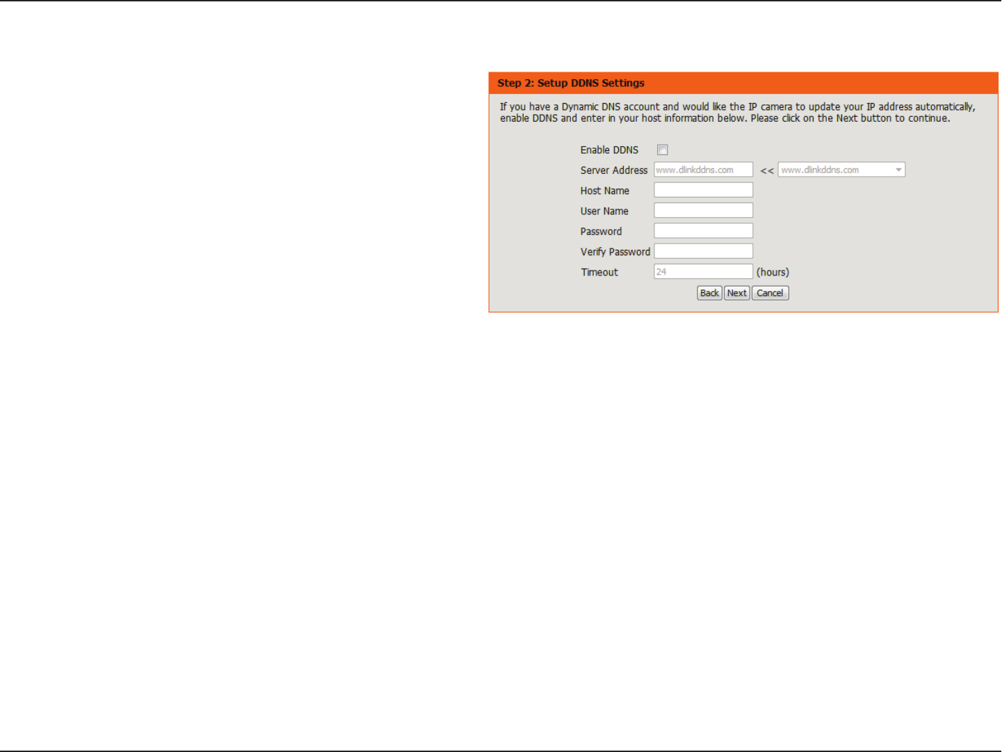
Section 4 - Conguration
A Dynamic DNS account allows you to access your camera over the Internet when you have an IP address that changes each time you connect to
the Internet. If you have a Dynamic DNS account, click Enable and enter the following details:
Click to enable the DDNS function.
(Dynamic Domain Name Server) will hold a DNS
host name and synchronize the public IP address
of the modem when it has been modied. The
username and password are required when using
the DDNS service.
Select your Dynamic DNS Server from the drop
down menu.
Enter the host name of the DDNS server.
Enter your username or e-mail address used to
connect to the DDNS.
Enter your password used to connect to the
DDNS server.
You can setup how often the camera noties the
DDNS server of its current global IP address by
entering a whole number in hours.
Click Next to continue.
Enable:
DDNS:
Server Address:
Host Name:
User Name:
Password:
Timeout:
27D-Link DCS-5222LB1 User Manual
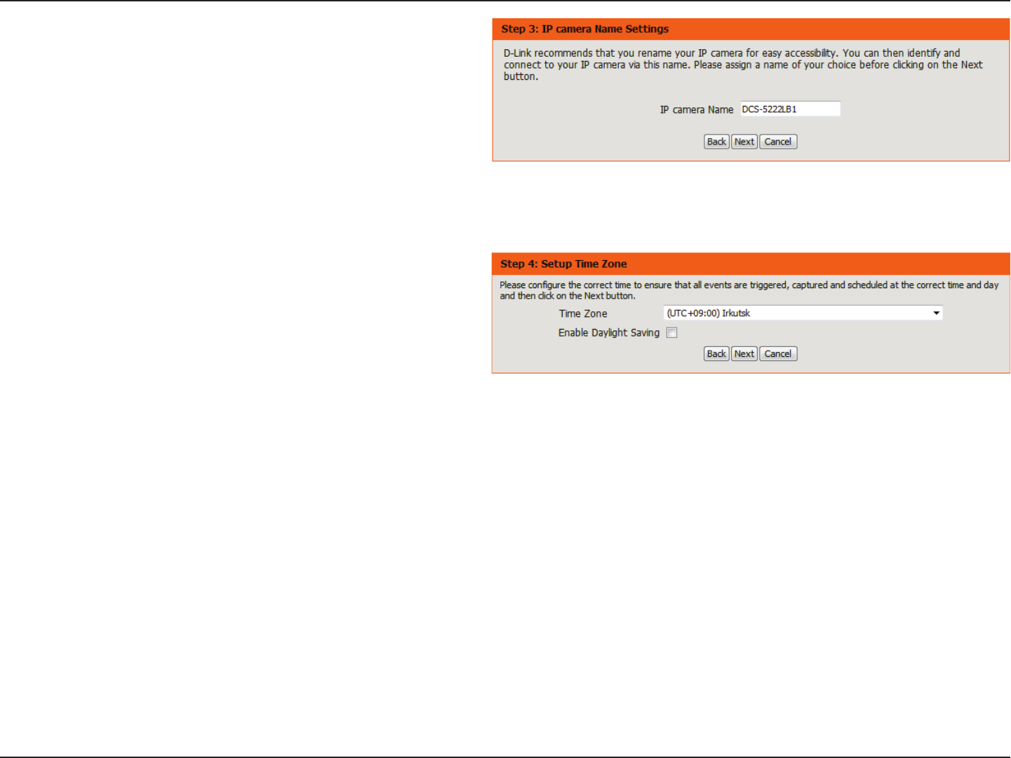
Section 4 - Conguration
Create a unique name for your camera. Click Next to continue.
Select the time zone that the camera is geographically located in so
that scheduled events occur at the correct time. If your time zone
observes daylight saving, check the Enable Daylight Saving box
and select Auto Daylight Saving to have DST set automatically
or select Set date and time manually to enable the drop-down
menu so that you can set the start and end time of daylight saving
yourself.
Click Next to continue.
28D-Link DCS-5222LB1 User Manual
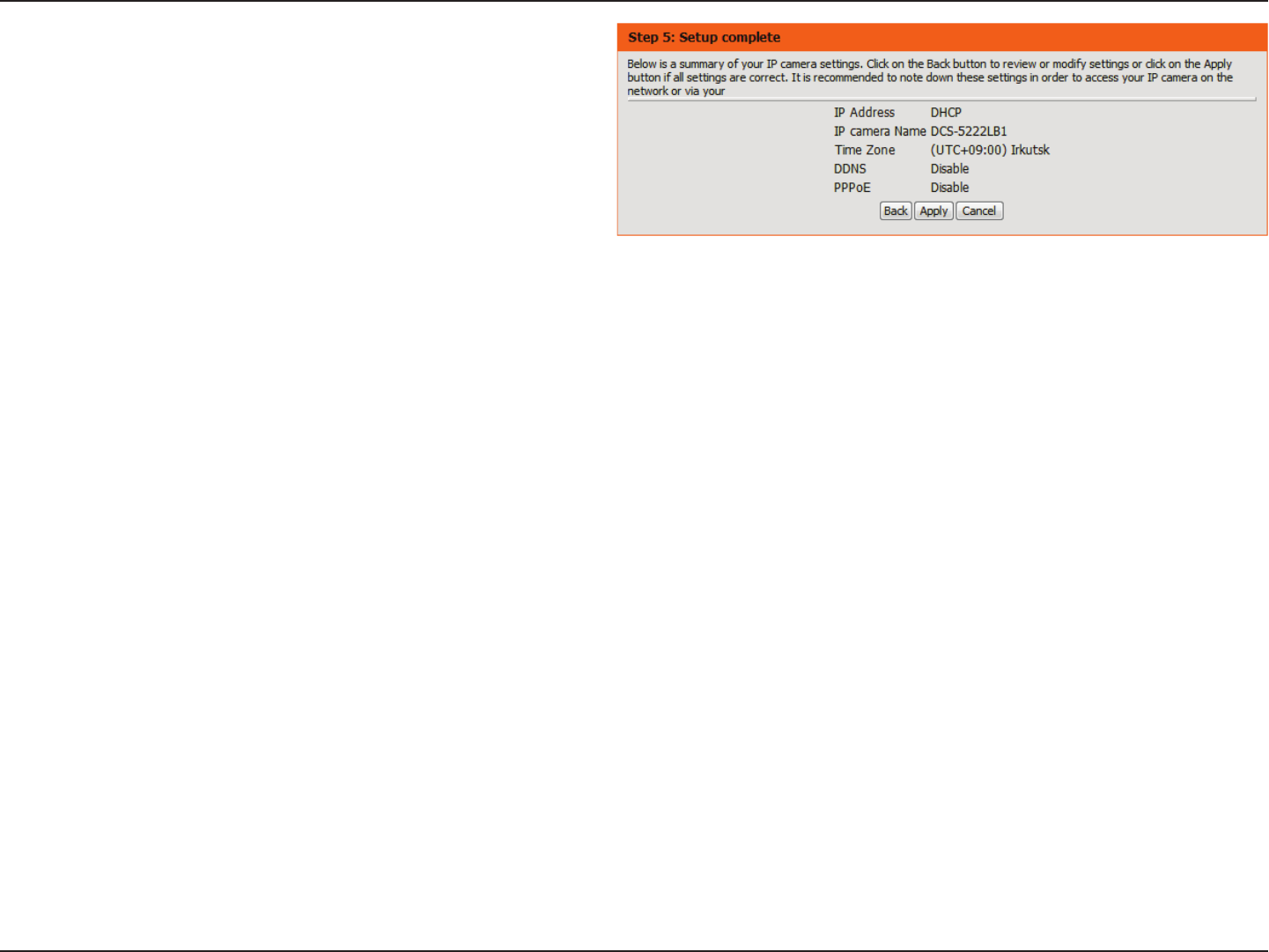
Section 4 - Conguration
A summary of the options you selected is displayed for conrmation.
If you are happy with the selected configuration, click Apply
otherwise click Back to make the required changes.
29D-Link DCS-5222LB1 User Manual
Section 4 - Conguration
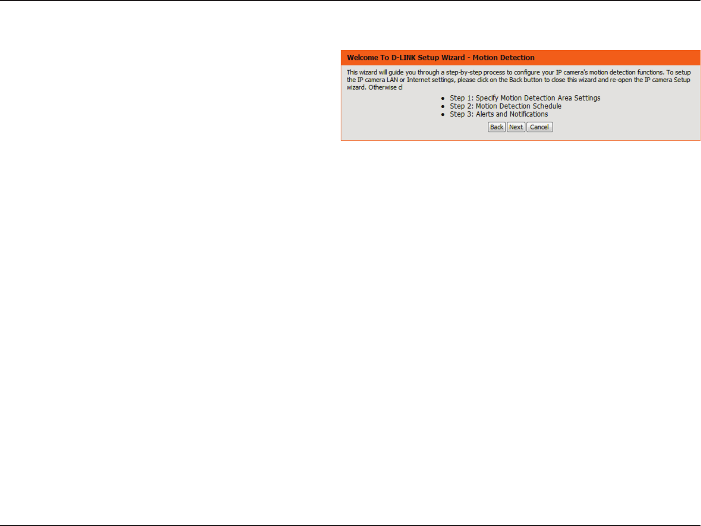
Motion Detection Setup Wizard
This wizard will guide you through a step-by-step process to con-
gure the motion detection feature of your new D-Link Camera
Click Next to continue.
30D-Link DCS-5222LB1 User Manual
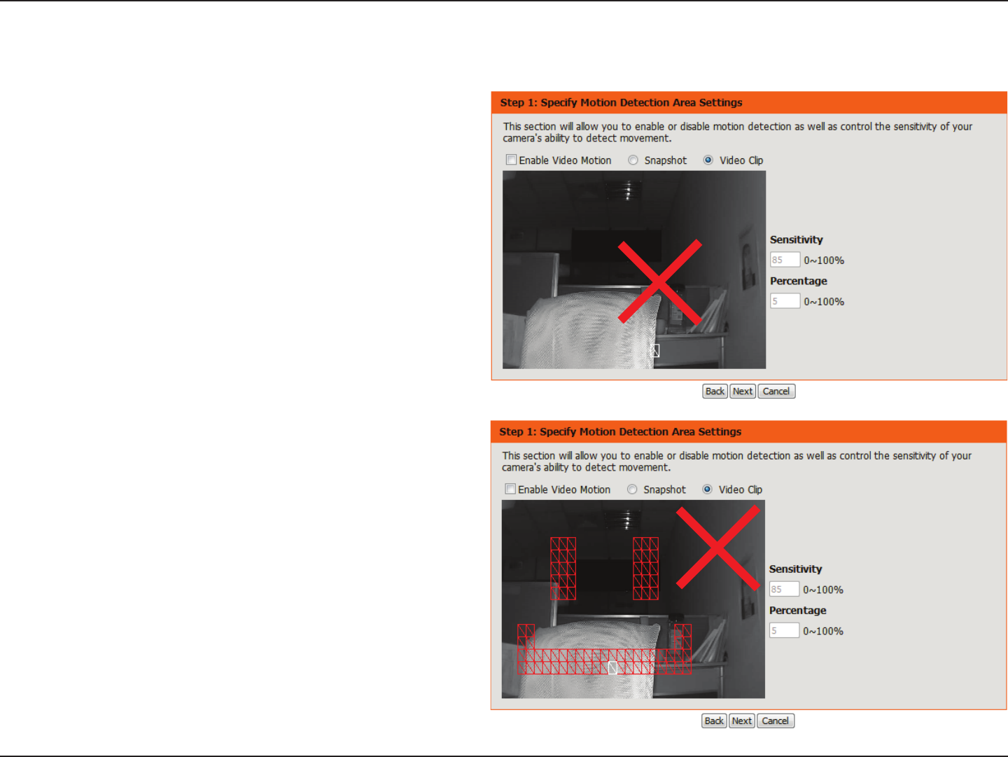
Section 4 - Conguration
Enabling the Video Motion option will allow your camera to use the motion detection feature. You may draw a nite motion area that will be used
for monitoring in a selected area.
Enable Video
Motion:
Enable PIR:
Sensitivity:
Clear:
Select this box to enable the motion detection
feature of your camera.
When this option is selected, use PIR (passive in-
frared) to detect motion.
Species the measurable dierence that would
indicate motion. Enter a value between 0 and 100.
Clears all motion detection areas from the picture.
Click Next to continue.
31D-Link DCS-5222LB1 User Manual
Section 4 - Conguration
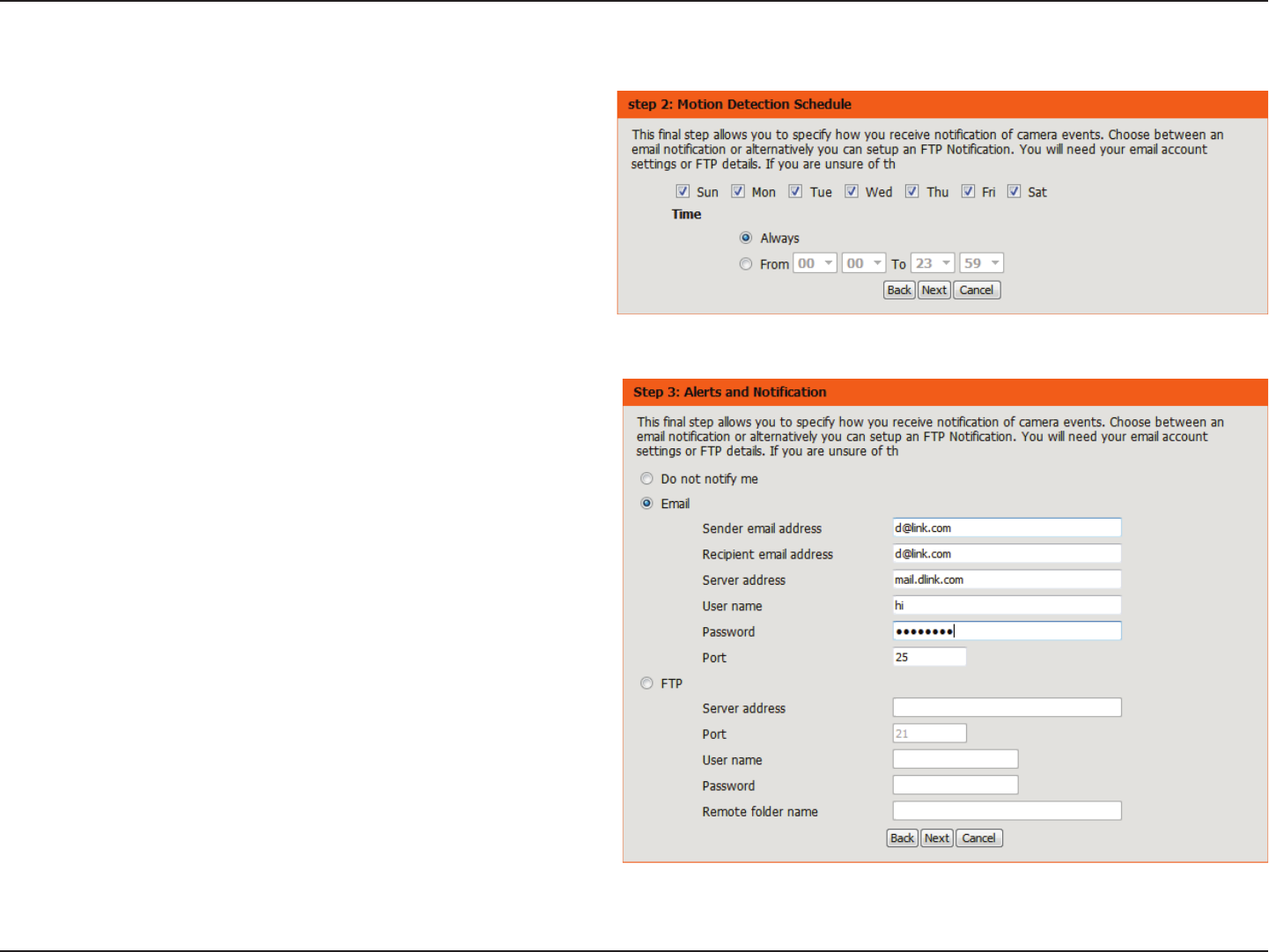
This step allows you to enable motion detection based on a customized schedule. Specify the day and hours. You may also choose to always record
whenever motion is detected.
Step 3
This step allows you to specify how you will receive event noti-
cations from your camera. You may choose not to receive notica-
tions, or to receive notications via e-mail or FTP.
Please enter the relevant information for your e-mail or FTP ac-
count.
Click Next to continue.
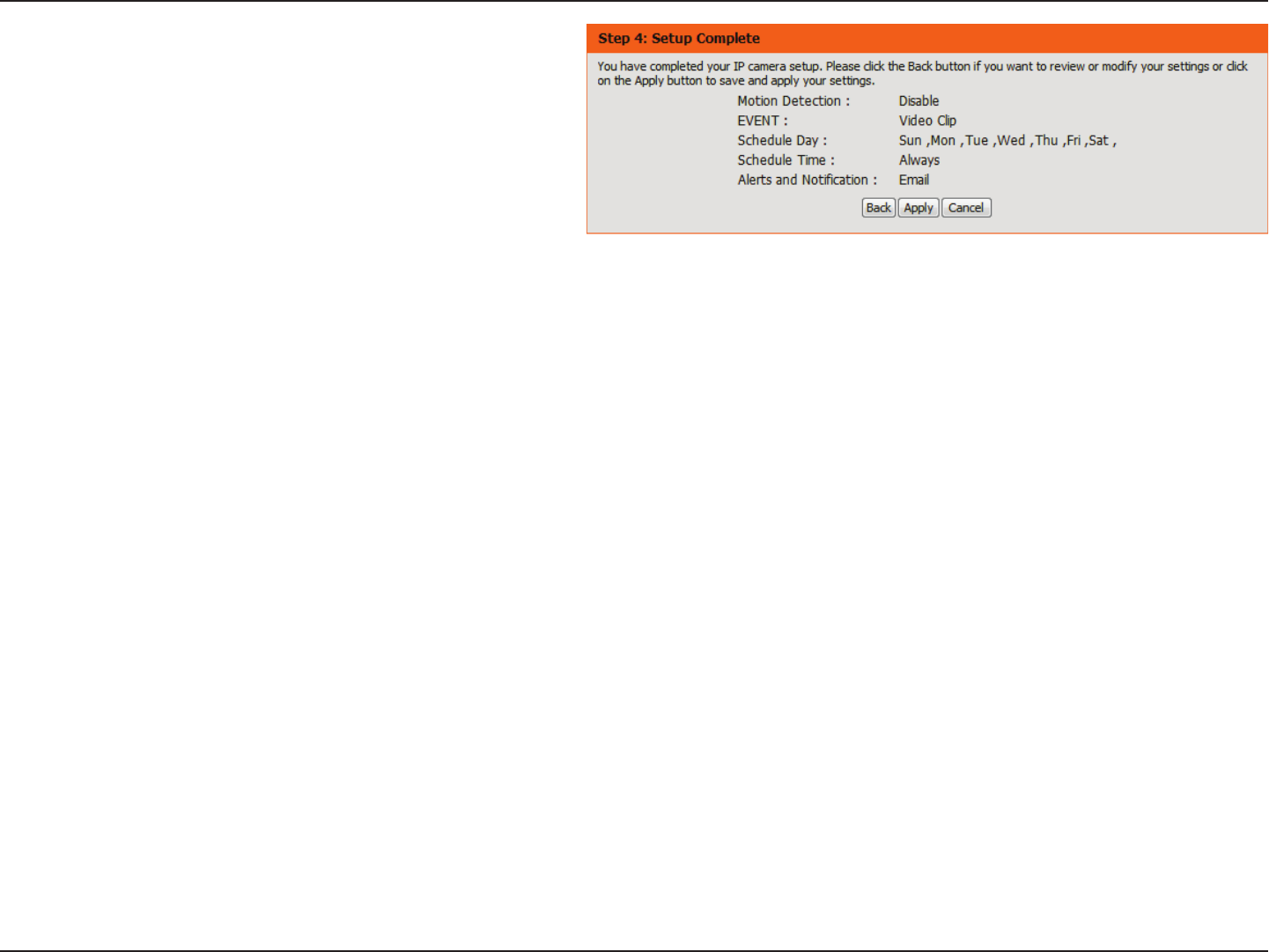
32D-Link DCS-5222LB1 User Manual
Section 4 - Conguration
A summary of the options you selected is displayed for
conrmation. If you are happy with the selected conguration,
click Apply otherwise click Back to make the required changes.
33D-Link DCS-5222LB1 User Manual
Section 4 - Conguration
Network
Use this section to congure the network connections for your camera. All relevant information must be entered accurately. After making any
changes, click the Save Settings button to save your changes.
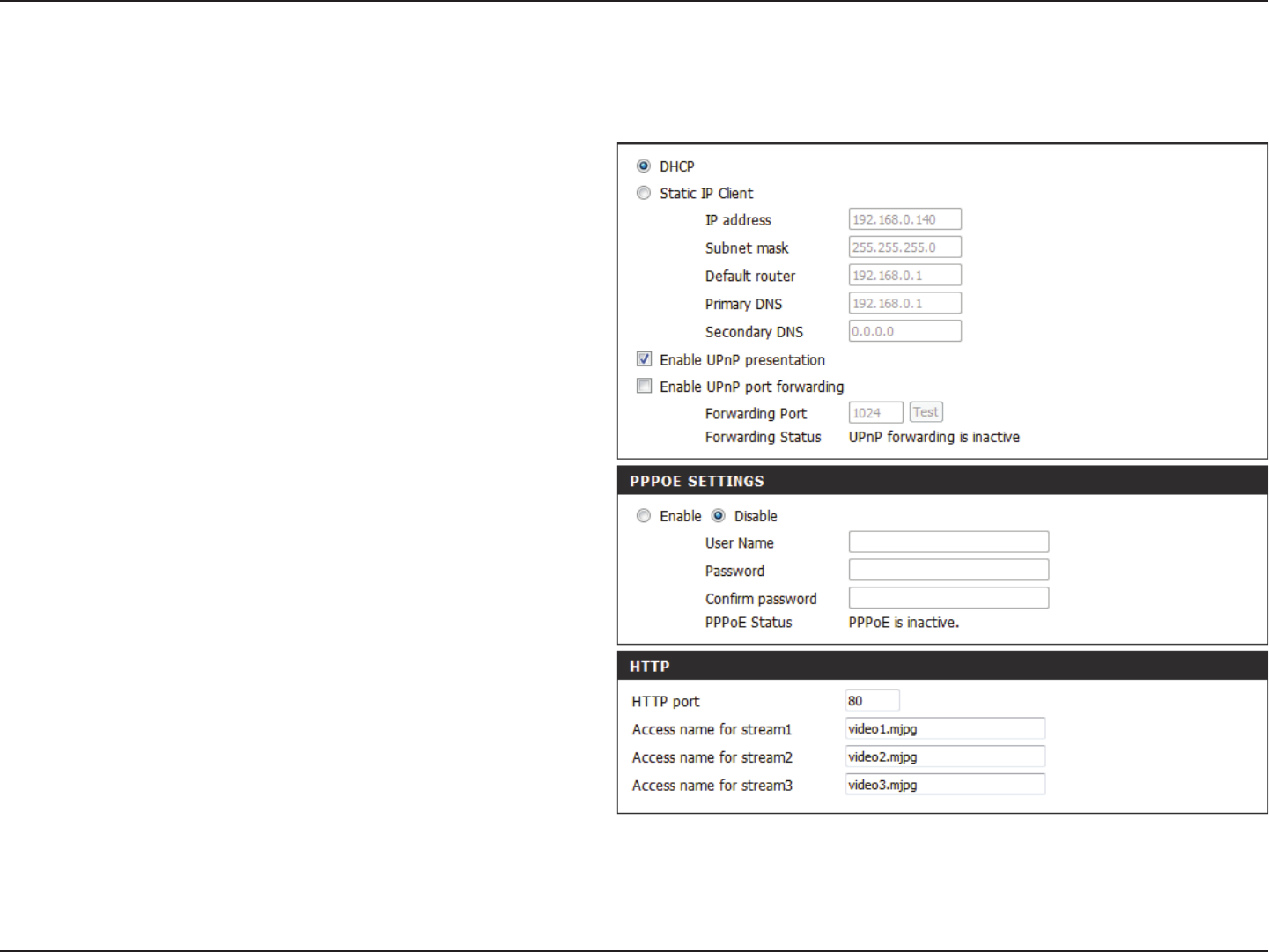
DHCP:
Static IP
Address:
IP Address:
Subnet Mask:
Default
Gateway:
Primary DNS:
Secondary
DNS:
Select this connection if you have a DHCP server
running on your network and would like your
camera to obtain an IP address automatically.
If you choose DHCP, you do not need to ll out the
IP address settings.
You may obtain a static or xed IP address and
other network information from your network
administrator for your camera. A static IP address
may simplify access to your camera in the future.
Enter the xed IP address in this eld.
This number is used to determine if the destination
is in the same subnet. The default value is
255.255.255.0.
The gateway used to forward frames to
destinations in a dierent subnet. Invalid gateway
settings may cause the failure of transmissions to
a dierent subnet.
The primary domain name server translates names
to IP addresses.
The secondary DNS acts as a backup to the primary
DNS.
34D-Link DCS-5222LB1 User Manual
Section 4 - Conguration
Enable UPnP
Presentation:
Enable
UPnP Port
Forwarding:
Enable PPPoE:
User Name /
Password:
HTTP Port:
Access Name
for Stream 1~3:
HTTPS Port:
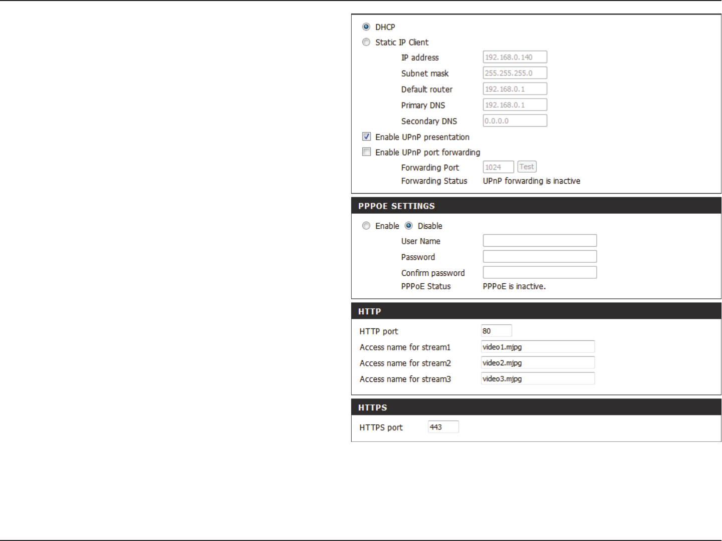
RTSP Port:
Enabling this setting allows your camera to be
congured as a UPnP device on your network.
Enabling this setting allows the camera to add port
forwarding entries into the router automatically
on a UPnP capable network.
Enable this setting if your network uses PPPoE.
Enter the username and password for your PPPoE
account. Re-enter your password in the Conrm
Password eld. You may obtain this information
from your ISP.
The default port number is 80.
The default name is video#.mjpg, where # is the
number of the stream.
You may use a PC with a secure browser to connect
to the HTTPS port of the camera. The default port
number is 443.
The port number that you use for RTSP streaming
to mobile devices, such as mobile phones or PDAs.
The default port number is 554. You may specify
35D-Link DCS-5222LB1 User Manual
Section 4 - Conguration
Enable CoS:
Enable QoS:
Enable IPV6:
Enable
Multicast for
stream
the address of a particular stream. For instance,
live1.sdp can be accessed at rtsp://x.x.x.x/video1.
sdp where the x.x.x.x represents the ip address of
your camera.
Enabling the Class of Service setting implements a
best-eort policy without making any bandwidth
reservations.
Enabling QoS allows you to specify a trac priority
policy to ensure a consistent Quality of Service
during busy periods. If the network camera is
connected to a router that itself implements QoS,
the router's settings will override the QoS settings
of the camera.
Enable the IPV6 setting to use the IPV6 protocol.
Enabling the option allows you to manually set up
the address, specify an optional IP address, specify
an optional router and an optional primary DNS.
The DCS-5222LB1 allows you to multicast each
of the available streams via group address and
specify the TTL value for each stream. Enter the
port and TTL settings you wish to use if you do not
want to use the defaults.
36D-Link DCS-5222LB1 User Manual
Section 4 - Conguration
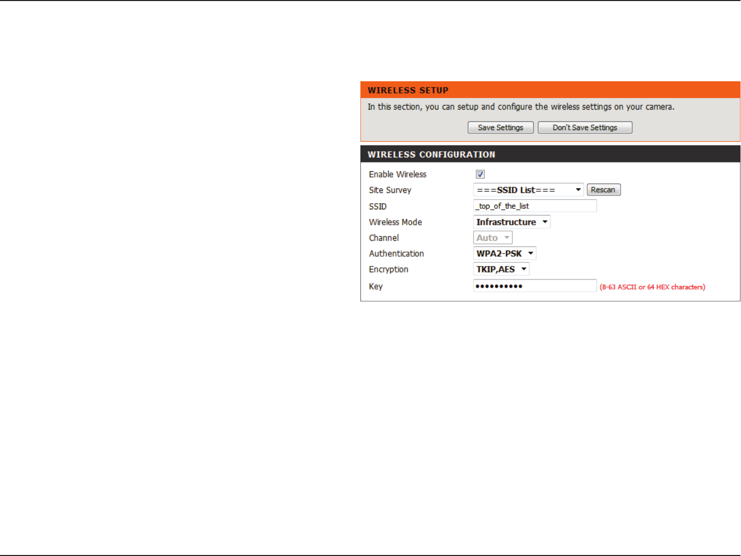
Wireless
To set up your Network camera’s wireless network interface settings, enable Wireless Settings in this window rst.
Check the box to enable wireless functionality or
uncheck the box to disable wireless functionality.
Click the Rescan button to scan for available wireless
networks. After scanning, select a wireless network from
the drop-down box that you want to connect to.
The name of the wireless network.
Use the drop-down box to select the mode of the
wireless network you wish to connect to. Infrastructure
is normally used to connect to an access point or router.
Ad-Hoc is usually used to connect directly to another
computer.
If you are using Ad Hoc mode, select the channel of the
wireless network you wish to connect to, or select Auto.
Select the type of authentication you are using on your
wireless network (Open, Shared (WEP), WPA-PSK, or
WPA-PSK2).
If you are using WPA-PSK or WPA-PSK2 authentication,
you will need to specify whether your wireless network
uses TKIP or AES encryption. If you use Open or Shared
authentication, this setting will be automatically set.
Enter the key or passphase to access a secure network.
Enable:
Site Survey:
Network Name:
Wireless Mode:
Channel:
Authentication:
Encryption:
Key:
After making any changes, click the Save Settings button to save your changes, or click the Don’t Save Settings button to discard your changes.
37D-Link DCS-5222LB1 User Manual
Section 4 - Conguration
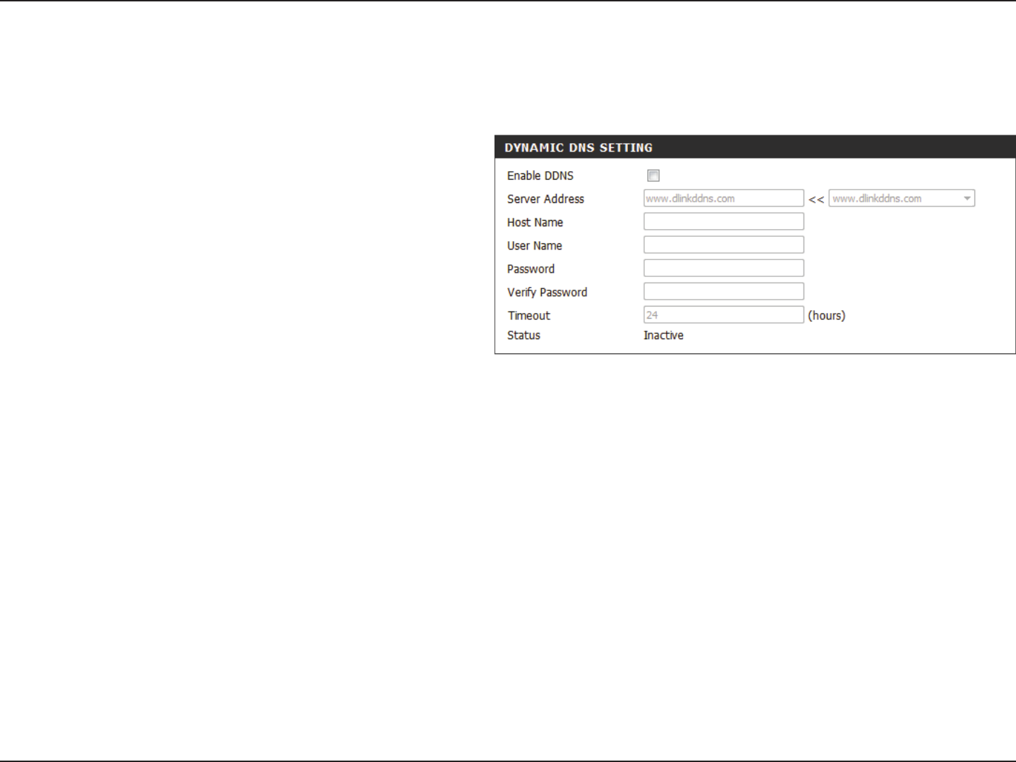
Dynamic DNS
Click to enable the DDNS function.
Select your Dynamic DNS Server from the drop-
down menu.
Enter the host name of the DDNS server.
Enter your username or e-mail address used to
connect to the DDNS.
Enter your password used to connect to the DDNS
server.
Enter your password again for verication.
You can setup how often the camera noties the
DDNS server of its current global IP address by
entering a whole number in hours.
Displays the connection status of your DDNS
account.
Enable DDNS:
Server Address:
Host Name:
User Name:
Password:
Verify
Password:
Timeout:
Status:
This section allows you to congure the DDNS setting for your camera. DDNS will allow all users to access your camera using a domain name instead
of an IP address.
38D-Link DCS-5222LB1 User Manual
Section 4 - Conguration
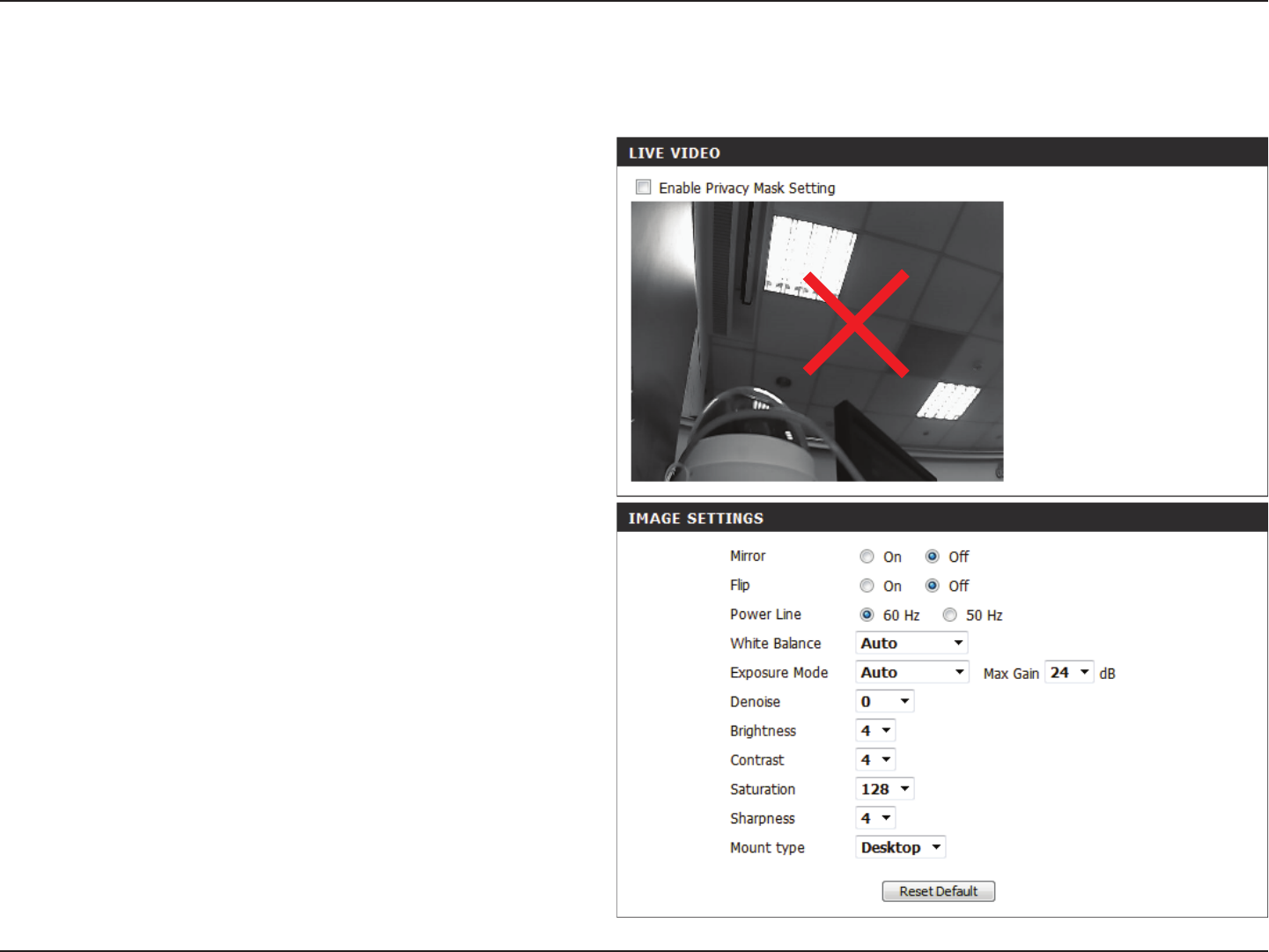
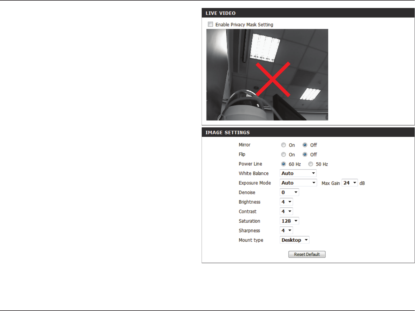
This section allows you to adjust the image and sensor settings for your camera.
Image Setup
The Privacy Mask setting allows you to specify 3
rectangular areas on the camera’s image to be
blocked/excluded from recordings and snapshots.
You may click and drag the mouse cursor over the
camera image to draw a mask area. Right click on
the camera image to bring up the following menu
options:
Disable All: Disables all mask areas
Enable All: Enables all mask areas
Reset All: Clears all mask areas.
This will ip the image horizontally.
This will ip the image vertically.
Select the frequency used by your power lines to
avoid interference or distortion.
Use the drop-down menu to change the white
balance settings to help balance colors in dierent
lighting environments. You can choose from Auto,
Outdoor, Indoor, Fluorescent, and Push Hold.
Enable Privacy
Mask:
Mirror:
Flip:
Power Line:
White Balance:
39D-Link DCS-5222LB1 User Manual
Section 4 - Conguration
Exposure
Mode:
Denoise:
Brightness:
Contrast:
Saturation:
Sharpness:
Mount type:
Changes the exposure mode. Use the drop-down
box to set the camera for Indoor, Outdoor, or Night
environments, or to Moving to capture moving
objects. The Low Noise option will focus on creat-
ing a high-quality picture without noise. You can
also create 3 dierent custom exposure modes.
The Max Gain setting will allow you to control the
maximum amount of gain to apply to brighten
the picture.
This setting controls the amount of noise
reduction that will be applied to the picture.
This adjusts the brightness of the camera image.
This adjusts the contrast of the camera image,
making a washed out image clearer or reducing
the brightness in an over exposed image.
This adjusts the color saturation. Saturation
controls the strength of color in the image.
Specify a value from 0 to 8 to specify how much
sharpening to apply to the image.
Select the correct mounting type from either
Ceiling or Desktop to ensure the PTZ controls
respond accurately.
Note: Mirror and Flip can be used if you have
mounted the DCS-5222LB1 on the ceiling.
40D-Link DCS-5222LB1 User Manual
Section 4 - Conguration
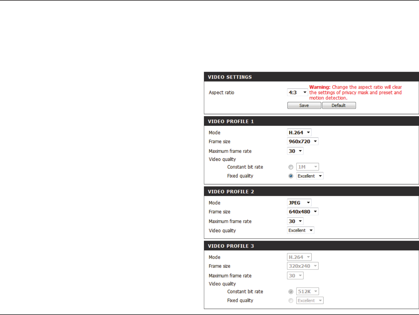
Audio and Video
You may congure up to 3 video proles with dierent settings for your camera. Hence, you may set up dierent proles for your computer and
mobile display. In addition, you may also congure the two-way audio settings for your camera. After making any changes, click the Save button to
save your changes.There are three sensor output selections (VGA, XGA, and SXGA). Do not select SXGA if you want to turn on the motion detection
feature.
Aspect ratio:
Mode:
Frame size /
View window
area:
Maximum
frame rate:
Set the aspect ratio of the video to 4:3 standard or
16:9 widescreen.
Set the video codec to be used to JPEG, MPEG-4,
or H.264.
Frame size determines the total capture
resolution, and View window area determines the
Live Video viewing window size. If the Frame size
is larger than the Live Video size, you can use the
ePTZ controls to view the full area.
16:9 1280 x 800, 1280 x 720, 800 x 450,
640 x 360, 480 x 270, 320 x 176,
176 x 144
4:3 1024 x 768, 800 x 600, 640 x 480,
480 x 360, 320 x 240, 176 x 144
Note: If your view window area is the same as
your frame size, you will not be able to use the
ePTZ function.
A higher frame rate provides smoother motion
for videos, and requires more bandwidth. Lower
frame rates will result in stuttering motion, and
requires less bandwidth.
41D-Link DCS-5222LB1 User Manual
Section 4 - Conguration
Note: Video Prole 3 is always set to MJPEG as the Encode Type to ensure that at least one of the Video Proles are viewable by non-IE browsers.
Video Prole 4 is for mobile devices only, and always uses H.264 as the Encode Type.
Note: Higher frame size, frame rate and bit rates will give you better video quality, but they will also require more network bandwidth. For best
viewing results on a mobile phone, we suggest setting the frame rate to 5 fps and the bit rate to 20 Kbps. Similarly, select appropriate audio encoding
for your bandwidth requirements.
After making any changes, click the Save Settings button to save your changes, or click the Don’t Save Settings button to discard your changes.
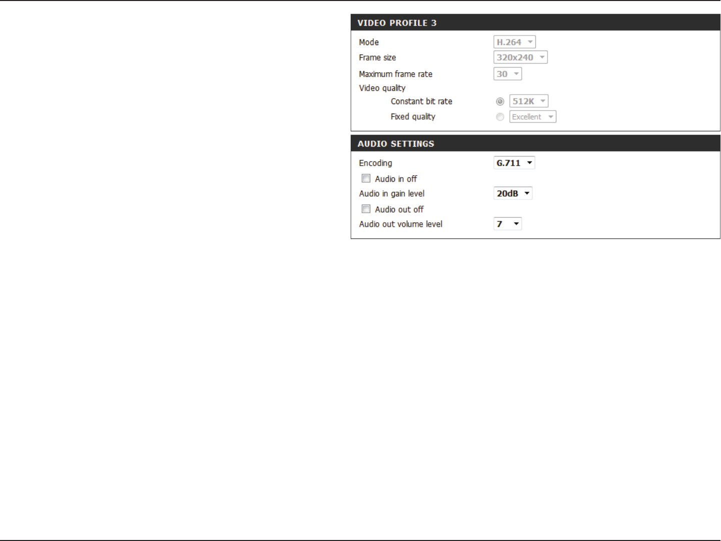
Video Quality:
Constant bit
rate:
Fixed quality:
Encoding:
Audio in o:
Audio in gain
level:
Audio out o:
Audio out
volume level:
This limits the maximum frame rate, which can
be combined with the “Fixed quality” option to
optimize the bandwidth utilization and video
quality. If xed bandwidth utilization is desired
regardless of the video quality, choose “Constant
bit rate” and select the desired bandwidth.
The bps will aect the bit rate of the video
recorded by the camera. Higher bit rates result in
higher video quality.
Select the image quality level for the camera to
try to maintain. High quality levels will result in
increased bit rates.
Choose between G.711, G.726 or AAC.
Selecting this checkbox will mute incoming
audio.
This setting controls the amount of gain applied
to incoming audio to increase its volume.
Selecting this checkbox will mute outgoing audio.
This setting controls the amount of gain applied
to outgoing audio to increase its volume.
42D-Link DCS-5222LB1 User Manual
Section 4 - Conguration
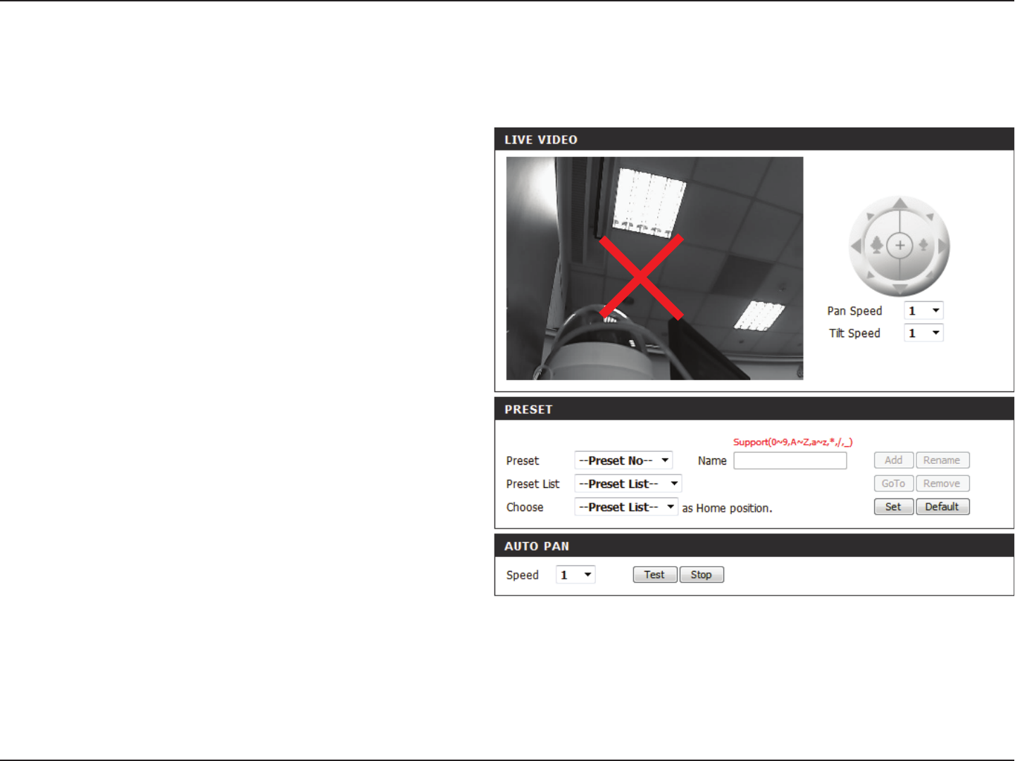
PTZ
This section allows you to congure the pan and tilt operations of your camera. You can specify the lens location for the Home button, and specify
up to 24 pre-set lens locations, allowing you to quickly view these pre-determined areas of the camera’s range from the Live Video screen.
Select the speed at which the camera will pan for
a full cycle from the drop-down list. Select a value
between 0 and 10, 0 being the slowest setting.
Select the speed at which the camera will tilt for a
full cycle from the drop-down menu. Select a value
between 0 and 10, 0 being the slowest.
Enter a name for your camera location and click
Add.
To add a preset to the sequence, select it from
the drop-down box at the bottom of this window,
then click the Add button. The preset name will
appear in the list.
You can rearrange your presets in the sequence by
selecting a preset in the sequence, then clicking
the arrow buttons to move it higher or lower in
the current sequence.
Clicking the trash can button will remove the
currently selected preset from the sequence.
Click to set the Home position with the default
setting.
Select the speed at which the camera will pan from
the drop-down menu. Select a value between 0
and 10, 0 being the slowest.
Click Save when nished.
Pan Speed:
Tilt Speed:
Preset Name:
Present List:
Choose as
Home:
Auto Pan
Speed:
43D-Link DCS-5222LB1 User Manual
Section 4 - Conguration
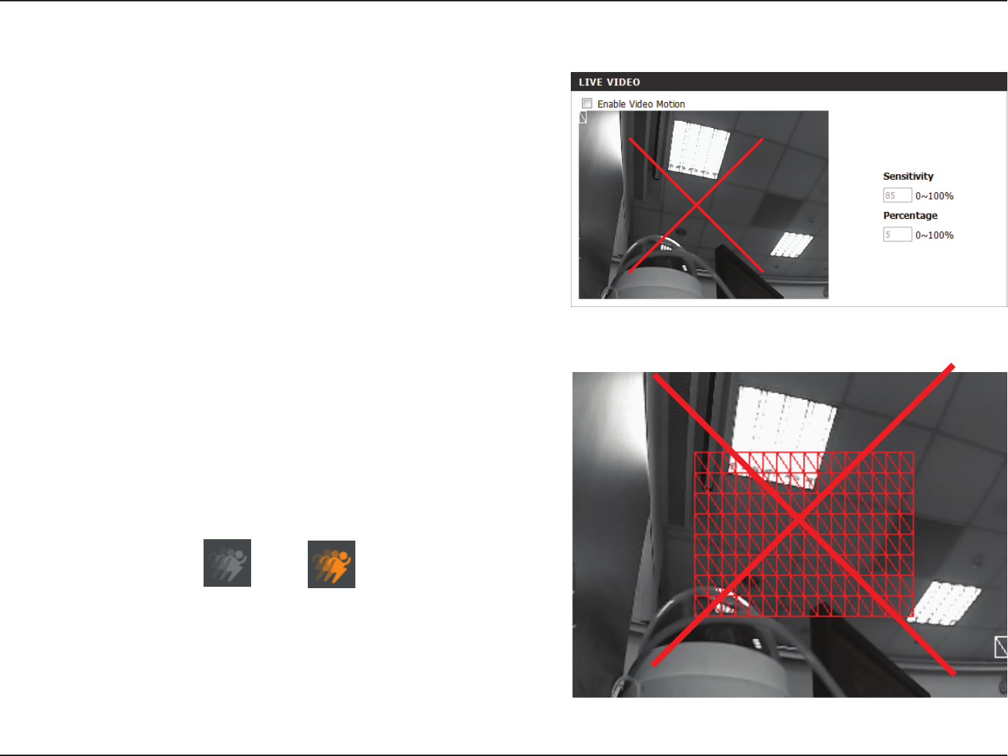
Motion Detection
Check this box to enable the motion detection feature of your
camera.
This setting adjusts how sensitive the camera will be to motion,
where 100% will be the most sensitive setting and 0% will be the
least sensitive setting.
Select Draw Motion Area to select the area of the picture to
monitor for movement to trigger recording or snapshot. Use your
mouse to click on the blocks that you would like to monitor for
motion. Select Erase Motion Area to remove the blocks and stop
the camera from monitoring that area of the picture.
Clicking this button will clear all motion detection zones.
This option allows you to set up Motion Detection on your network camera.
Enable Video
Motion:
Sensitivity:
Drawing Mode:
Clear:
The motion notication will continue to blink as long as motion is detected. If no
additional motion is detected, it will return to its original state after eight seconds.
After making any changes, click the Save Settings button to save your changes, or click
the Don’t Save Settings button to discard your changes.
Note: If the camera is set to SXGA mode in Audio and Video, Motion Detection is disabled.
The red grid on the right indicates an area that has been selected for motion detection.
When motion is detected, the LIVE VIDEO page will display a blinking orange motion
video icon like the one below.
MotionNo Motion
44D-Link DCS-5222LB1 User Manual
Section 4 - Conguration
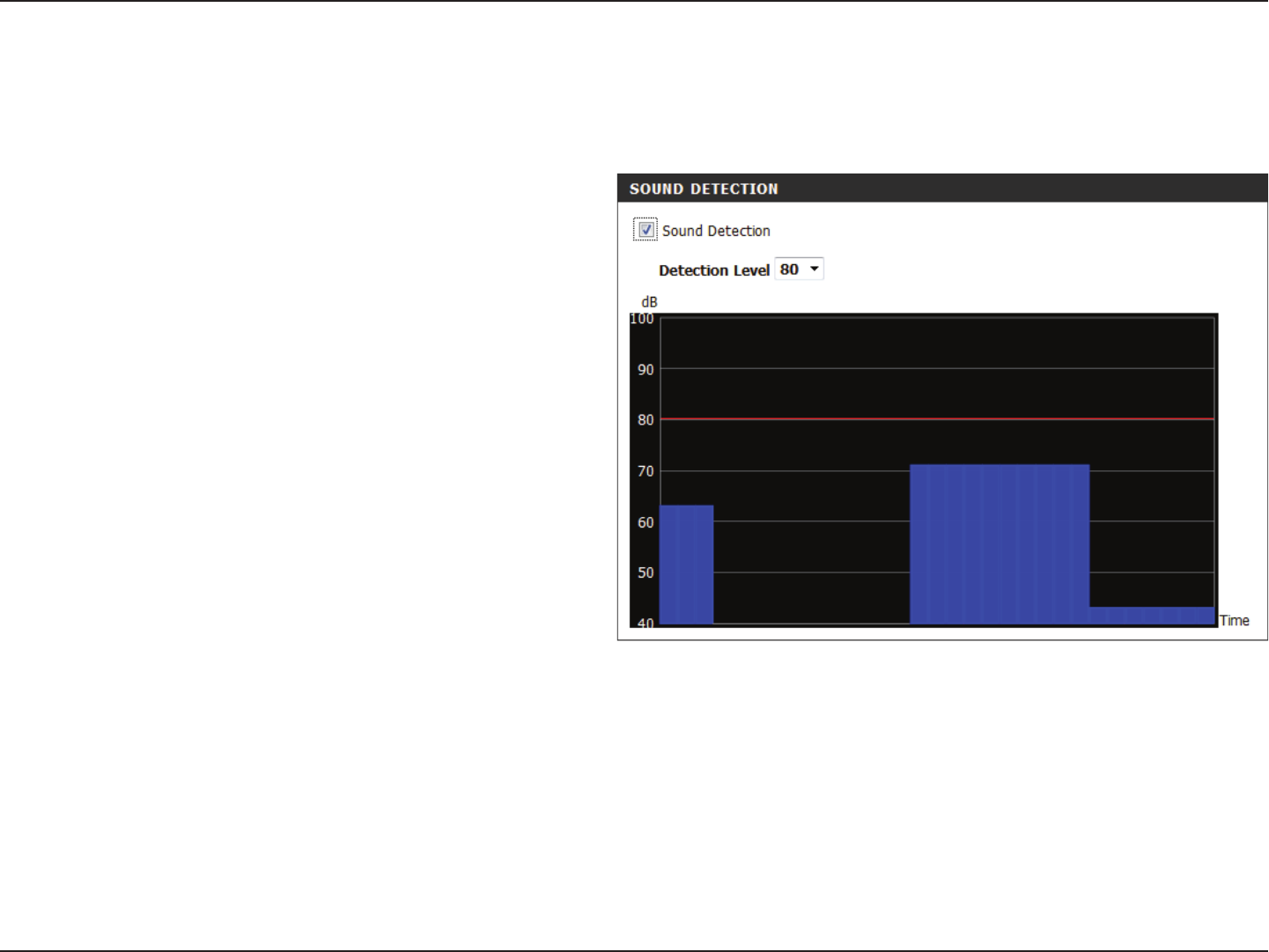
Sound Detection
Check this box to enable the motion detection feature
of your camera.
Species the measurable level that would indicate
sound. Please enter a value between 50 and 90, the
higher the number the more sensitive the camera
will be to sound.
Enabling Sound Detection will allow your camera to use the built-in microphone to trigger events with audio. If this option is selected, the trigger
by option under SD recording, Video Clip, or Snapshot should also be selected.
Enable Sound
Detection:
Detection Level:
After making any changes, click the Save Settings button to save your
changes, or click the Don’t Save Settings button to discard your changes.
45D-Link DCS-5222LB1 User Manual
Section 4 - Conguration
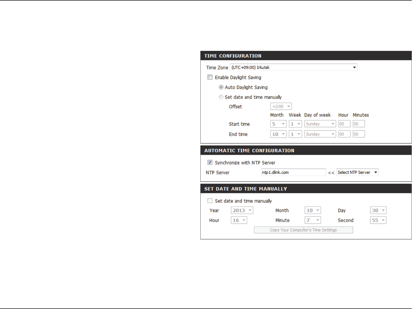
Time and Date
This section allows you to congure the settings of the internal system clock for your camera.
Time Zone:
Enable Daylight
Saving:
Auto Daylight
Saving:
Synchronize
NTP Server:
Set the Date and
Time Manually:
Copy your
Computer’s
Time Settings:
Select the time zone for your region from the
drop-down menu.
Check this if the camera is in a region where
daylight saving is observed.
This option will adjust Daylight Saving Time
automatically.
Network Time Protocol will synchronize your
camera with an Internet time server. You can
enter an IP address of a server or select from
the drop-down menu.
Select this to set the time manually.
Click to synchronize the time information
from your PC.
After making any changes, click the Save Settings button to save
your changes, or click the Don’t Save Settings button to discard
your changes.
46D-Link DCS-5222LB1 User Manual
Section 4: Conguration
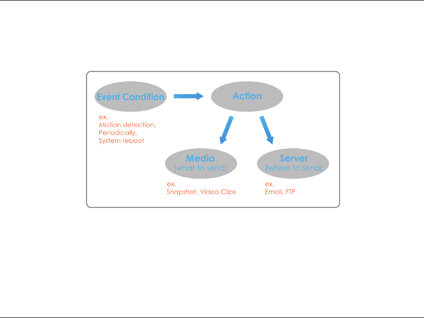
Event Setup
In a typical application, when motion is detected, the DCS-5222LB1 sends images to a FTP server or via e-mail as notications. As shown in the
illustration below, an event can be triggered by many sources, such as motion detection or external digital input devices. When an event is
triggered, a specied action will be performed. You can congure the network camera to send snapshots or videos to your e-mail address or FTP
site.
To start plotting an event, it is suggested to congure server and media columns rst so that the network camera will know what action shall be
performed when a trigger is activated.
47D-Link DCS-5222LB1 User Manual
Section 4 - Conguration
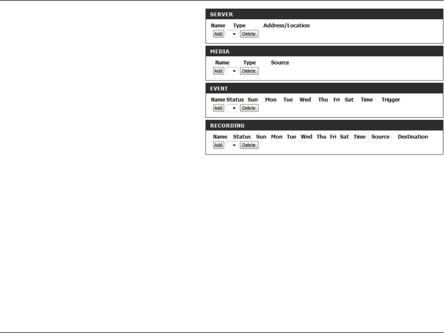
The Event Setup page includes 4 dierent sections.
• Server
• Media
• Event
• Recording
1. To add a new item - "event, server or media," click Add. A
screen will appear and allow you to update the elds accord-
ingly.
2. To delete the selected item from the pull-down menu of event,
server or media, click Delete.
3. Click on the item name to pop up a window for modifying.
48D-Link DCS-5222LB1 User Manual
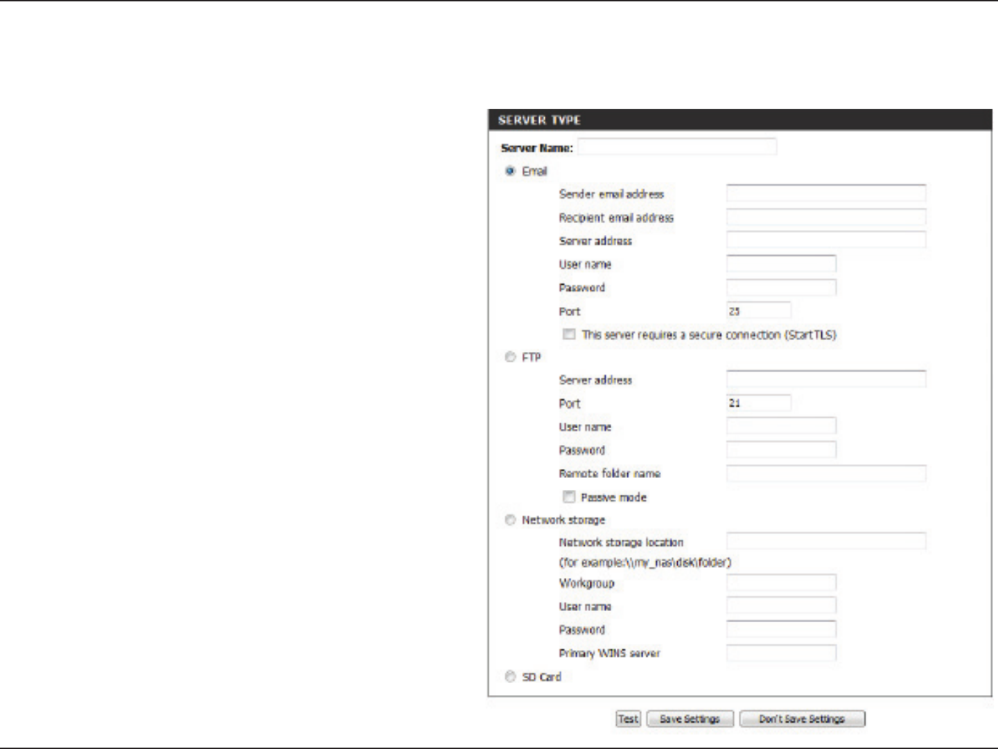
Section 4 - Conguration
Add Server
Server Name:
E-mail:
FTP:
Network Storage:
SD Card:
Enter the unique name of your server.
Enter the conguration for the target e-mail
server account.
Enter the conguration for the target FTP server
account.
Specify a network storage device. Only one
network storage device is supported.
Use the camera's onboard SD card storage.
You can congure up to 5 servers to save snapshots and/or video to. After making any changes, click the Save Settings button to save your changes.
49D-Link DCS-5222LB1 User Manual
Section 4 - Conguration
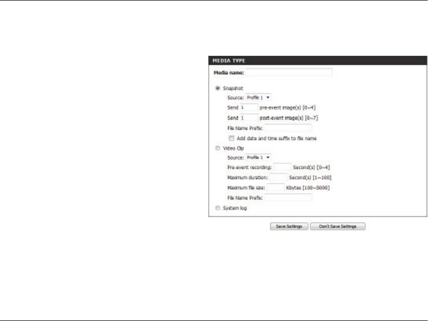
Add Media
Media Name:
Snapshot:
Source:
Send pre-event
image(s) [0~4]:
Send post-event
image(s) [0~7]:
File name prex:
Add date and
time sux to le
name:
Video clip:
There are three types of media, Snapshot, Video Clip, and System Log. After making any changes, click the Save Settings button to save your
changes.
Enter a unique name for media type you want to
create.
Select this option to set the media type to snap-
shots.
Set the video prole to use as the media source.
Refer to Audio and Video on 第 40 第第第Audio and
Video第 for more information on video proles.
Set the number of pre-event images to take.
Pre-event images are images taken before the
main event snapshot is taken.
Set the number of post-event images to take.
Post-event images are images taken after the
main event snapshot is taken. You can set up to
7 post-event images to be taken.
The prex name will be added on the le name.
Check it to add timing information as le name
sux.
Select this option to set the media type to video
clips
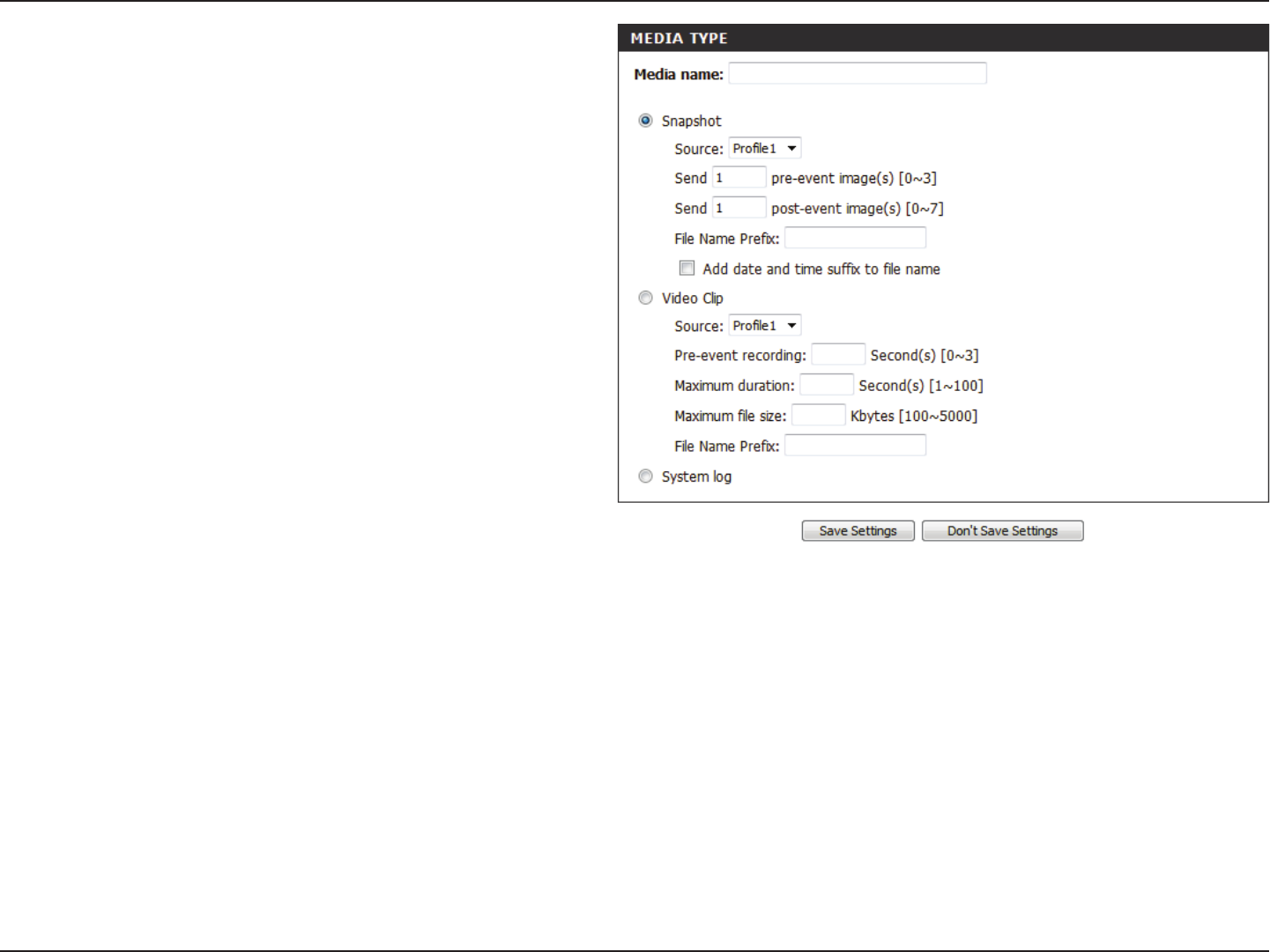
50D-Link DCS-5222LB1 User Manual
Section 4 - Conguration
Source:
Pre-event
recording:
Maximum
duration:
Maximum le
size:
File name
prex:
System log:
Set the video prole to use as the media source.
Refer to “Audio and Video” on page 51 for more
information on video proles.
This sets how many seconds to record before the
main event video clip starts. You can record up
to 3 seconds of pre-event video.
Set the maximum length of video to record for
your video clips.
Set the maximum le size to record for your
video clips.
This is the prex that will be added to the le-
name of saved video clips.
Select this option to set the media type to sys-
tem logs. This will save the event to the camera
system log, but will not record any snapshots or
video.
51D-Link DCS-5222LB1 User Manual
Section 4 - Conguration
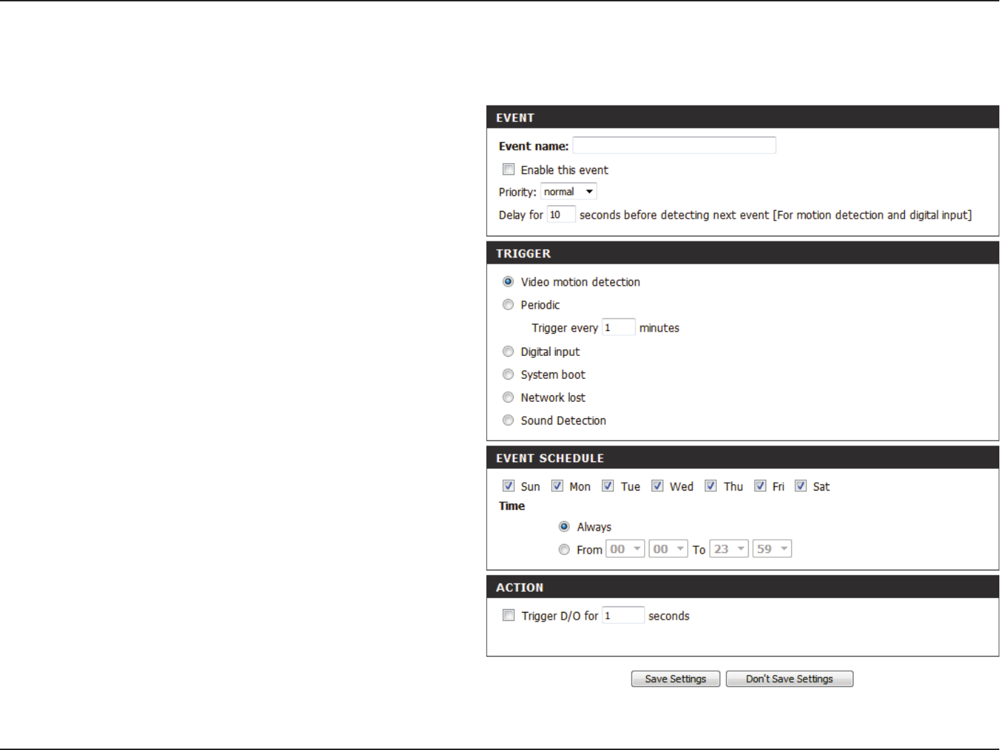
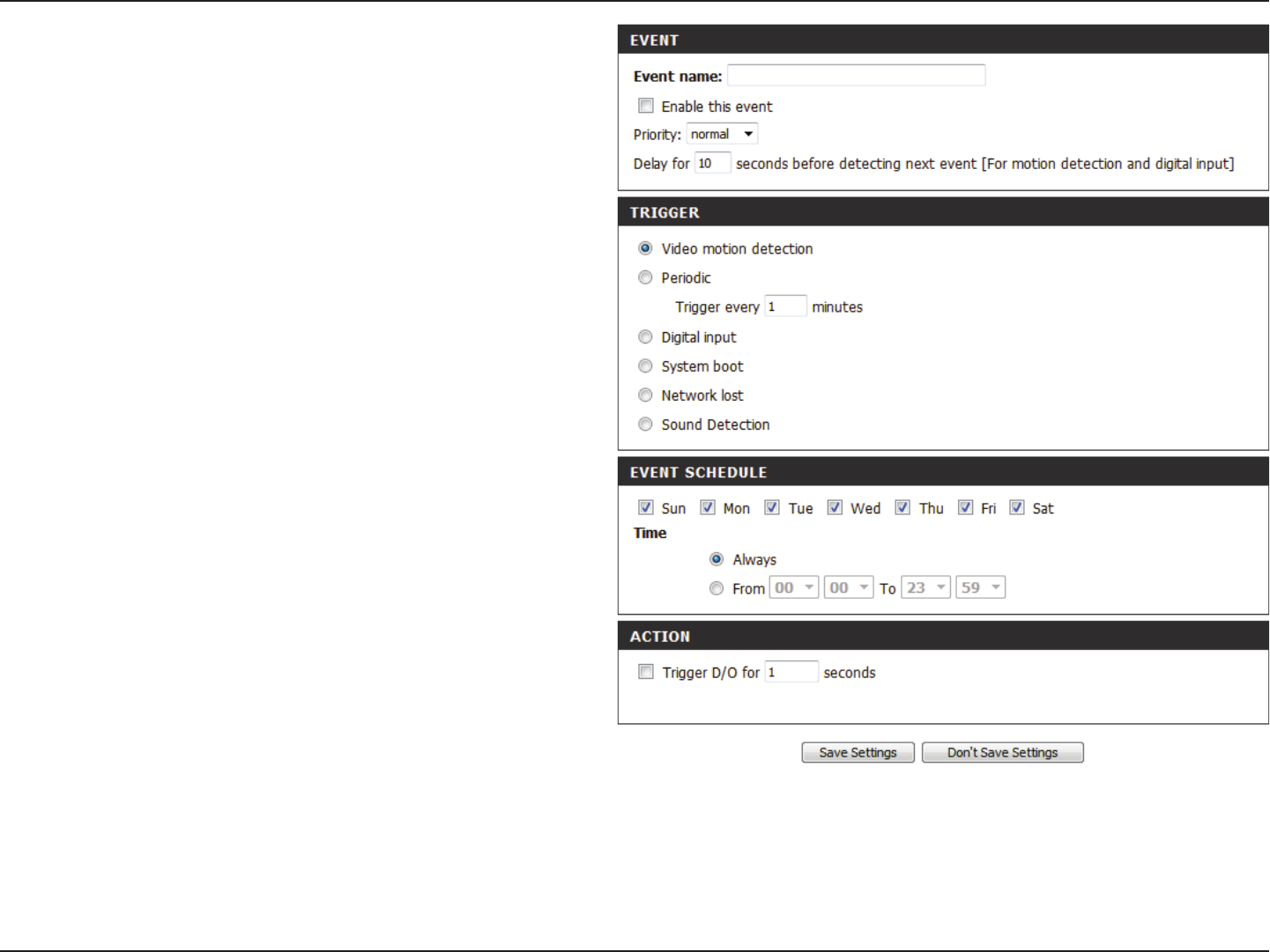
Add Event
Create and schedule up to 2 events with their own settings here. After making any changes, click the Save Settings button to save your changes.
Event name:
Enable this
event:
Priority:
Delay:
Trigger:
Video Motion
Detection:
Periodic:
Digital input:
System Boot:
Network Lost:
Enter a name for the event.
Select this box to activate this event.
Set the priority for this event. The event with
higher priority will be executed rst.
Select the delay time before checking the next
event. It is being used for both events of mo-
tion detection and digital input trigger.
Specify the input type that triggers the event.
Motion is detected during live video monitor-
ing. Select the windows that need to be moni-
tored.
The event is triggered in specied intervals. The
trigger interval unit is in minutes.
The external trigger input to the camera.
Triggers an event when the system boots up.
Triggers an event when the network connec-
tion is lost.
52D-Link DCS-5222LB1 User Manual
Section 4 - Conguration
Sound Detection:
Passive Infrared
Sensor:
Time:
Trigger D/O:
Triggers an event when an audio trigger is
recorded.
Triggers an event when the PIR sensor is acti-
vated by moving infrared objects even in dark
environment.
Select Always or enter the time interval.
Select to trigger the digital output for a specic
number of seconds when an event occurs.
53D-Link DCS-5222LB1 User Manual
Section 4 - Conguration
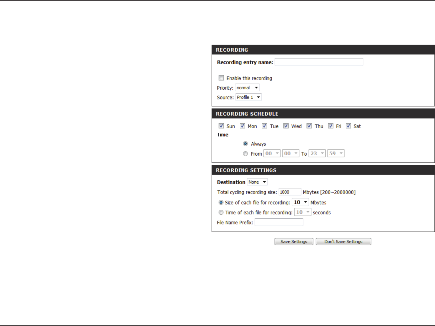
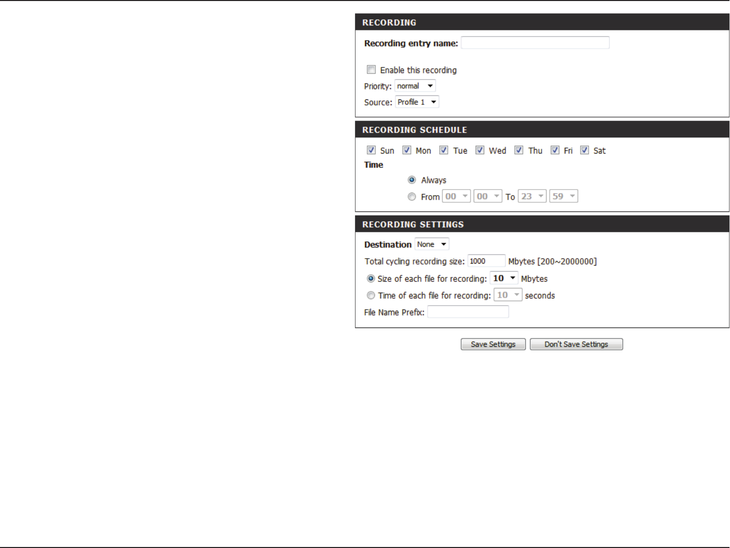
Add Recording
Recording entry
name:
Enable this
recording:
Priority:
Source:
Recording
schedule:
Recording
settings:
Destination:
The unique name of the entry.
Select this to enable the recording function.
Set the priority for this entry. The entry with a
higher priority value will be executed rst.
The source of the stream.
Scheduling the recording entry.
Conguring the setting for the recording.
Select the folder where the recording le will
be stored.
Here you can congure and schedule the recording settings. After making any changes, click the Save Settings button to save your changes.
54D-Link DCS-5222LB1 User Manual
Section 4 - Conguration
Total cycling
recording size:
Size of each le
for recording:
Time of each le
for recording:
File Name Prex:
Please input a HDD volume between 1MB and
2TB for recording space. The recording data will
replace the oldest record when the total
recording size exceeds this value. For example,
if each recording le is 6MB, and the total
cyclical recording size is 600MB, then the
camera will record 100 les in the specied
location (folder) and then will delete the oldest
le and create new le for cyclical recording.
Please note that if the free HDD space is not
enough, the recording will stop. Before you set
up this option please make sure your HDD has
enough space, and it is better to not save other
les in the same folder as recording les.
If this is selected, les will be separated based
on the le size you specify.
If this is selected, les will be separated based
on the maximum length you specify.
The prex name will be added on the le name
of the recording le(s).
55D-Link DCS-5222LB1 User Manual
Section 4 - Conguration
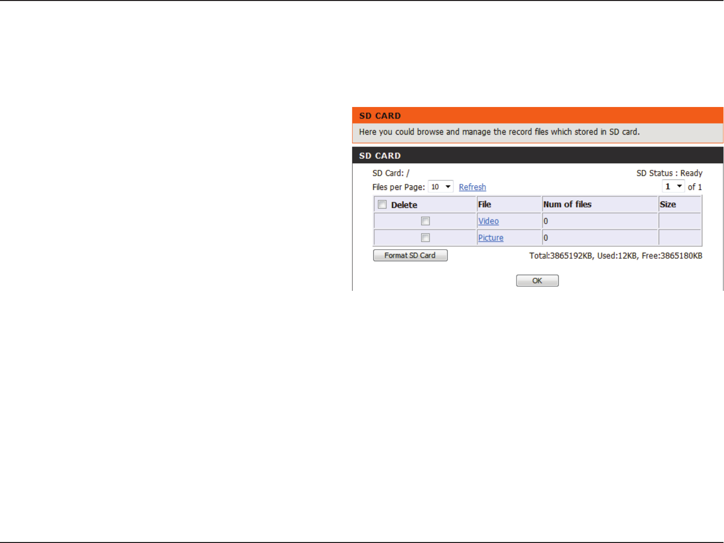
SD Management
This page allows you to browse and manage the recorded les on an SD card which has been inserted into the camera.
Note: It is recommended to use the Format SD Card function when inserting an SD card for the rst time.
Format SD
Card:
Delete:
Name:
Size:
Refresh:
Files per page:
Pages:
Click to automatically format the SD Card and
create a folder for video. Formatting your SD
Card will erase all data currently saved.
Click the checkbox in front of the Delete button
to select les meant for deletion. The Delete
button is used to delete the les which are
selected.
The name of le recording.
The le’s size.
Click to refresh the page.
Select the number of les to be displayed on a
single page. The maximum is 100 les.
Show the current and total number of pages.
56D-Link DCS-5222LB1 User Manual
Section 4 - Conguration
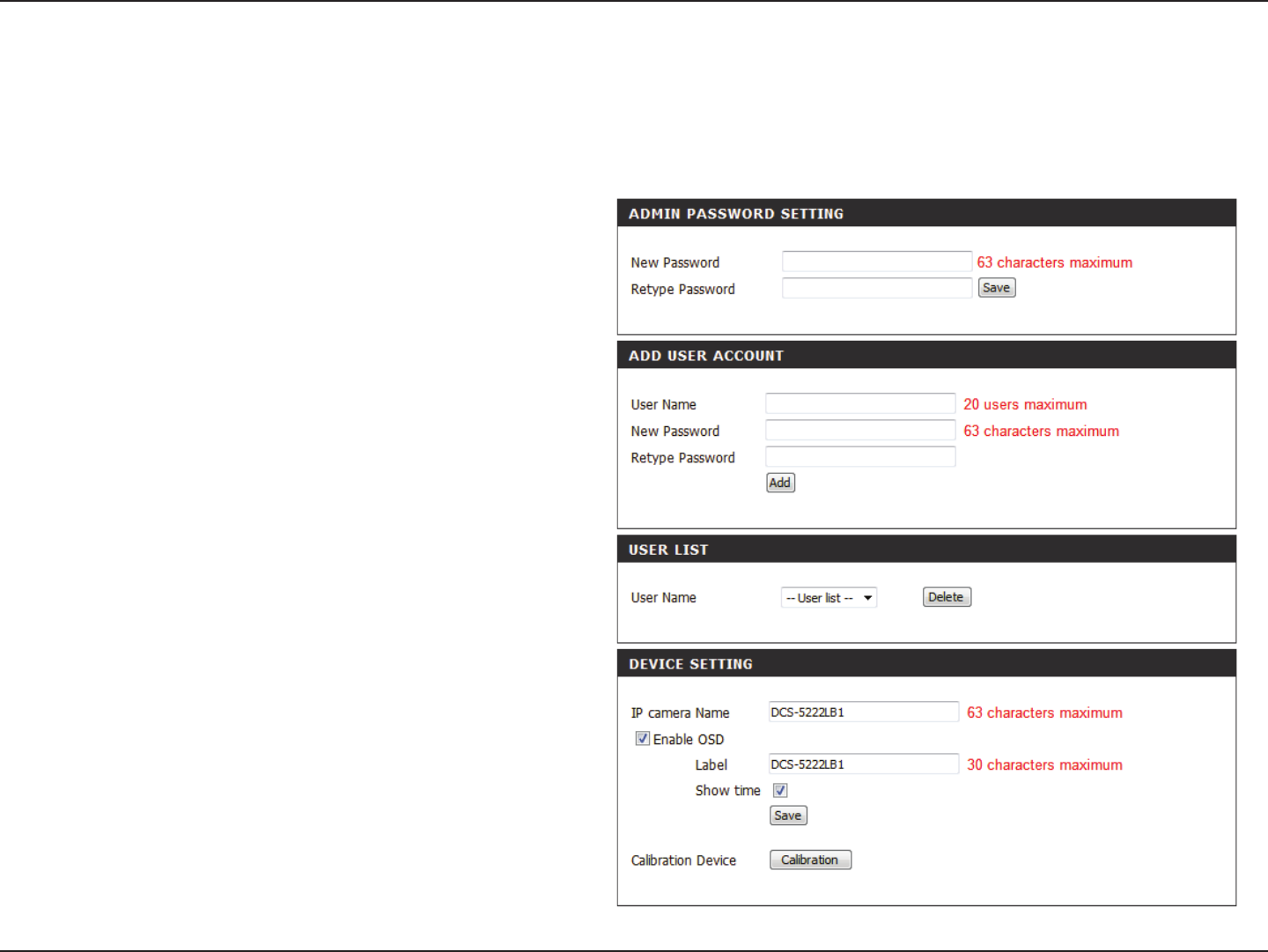
This section lets you change the admin password
used to log into the camera and change settings.
After installing the camera for the rst time, it is
highly recommended that you change the admin
password for security purposes.
Enter the existing password, then enter your new
password. Click Save to apply your new settings.
You may create user accounts to allow others to log
into your camera to view the live camera feed. Users
cannot change any settings.
Enter the User Name you wish to use for the new
user account and then create a password for that
account. Click Add to save your account.
Select a user from the drop-down menu and click
Delete to remove the user account from having
access to the camera images.
Enter the name of your camera. This is useful if you
have multiple cameras.
This will enable the information bar On Screen
Display (OSD) to appear when viewing video.
This is the text label that will appear on the OSD.
Maintenance
Admin
This section allows you to change the administrator’s password and congure the server settings for your camera. You can also manage the user
account(s) that enable access to your camera.
Admin Password
Setting:
Add User
Account:
User List:
Camera Name:
Enable OSD:
Label:
57D-Link DCS-5222LB1 User Manual
Section 4 - Conguration
Time Stamp:
Calibrate the
Device:
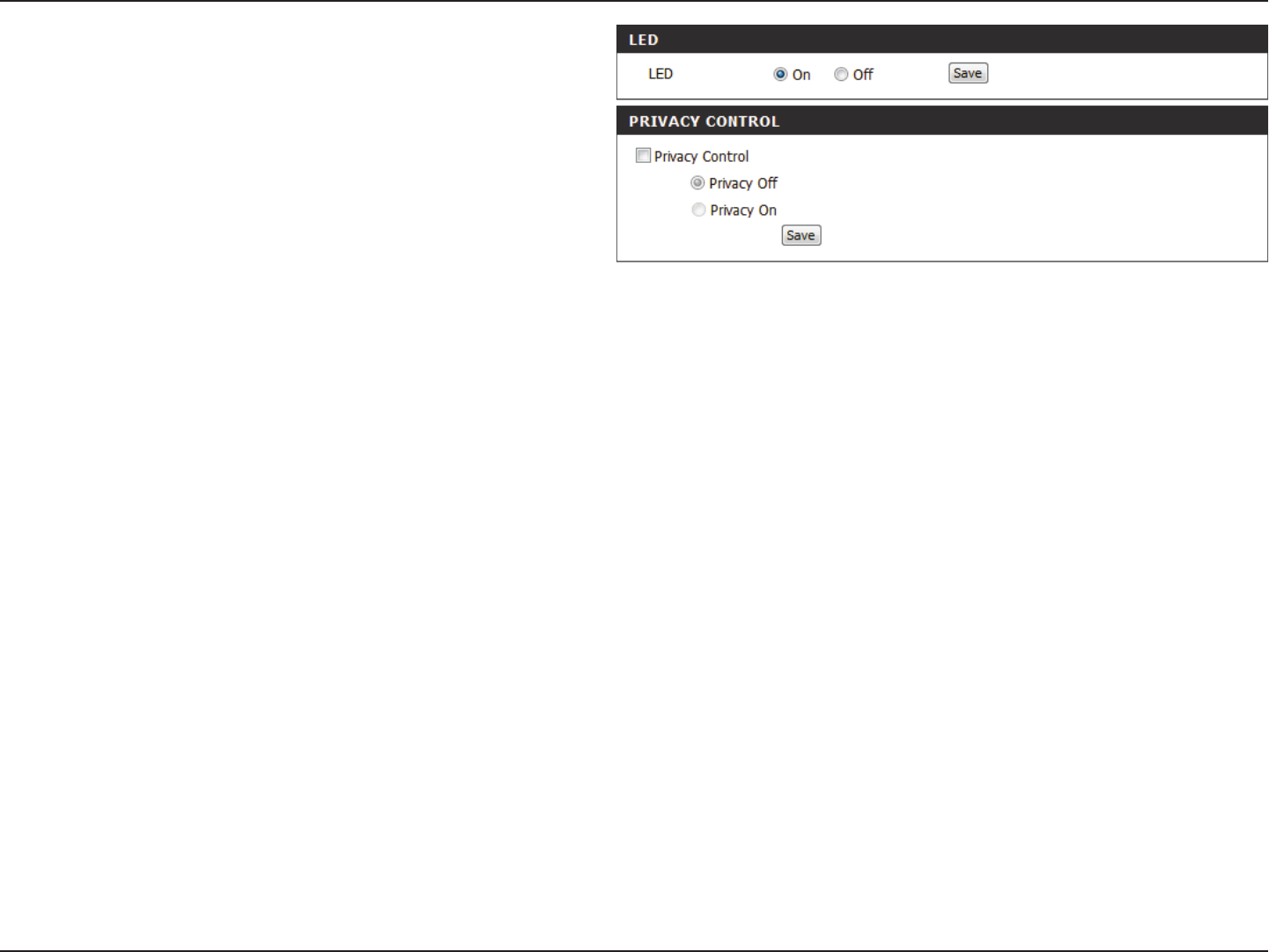
LED Light:
Privacy Mode:
If checked, the current time will be displayed on
the OSD.
Clicking this button will calibrate the camera so
that the P/T/Z apparatus functions correctly. The
camera is automatically calibrated whenever it is
powered on and initialized or reset. Should the
camera’s pan, tilt, and zoom functions begin to
behave incorrectly, or if the device has been jarred
or handled improperly, you may need to recalibrate
the camera manually by pressing this button.
This will turn the camera’s front LED indicator on
or o.
Select on/o or schedule the privacy mode for your
camera to ensure privacy. When the privacy mode
is turned on, the camera hides the lens by rolling it
back into the unit.
After making any changes, click the Save button to
save your changes.
58D-Link DCS-5222LB1 User Manual
Section 4 - Conguration
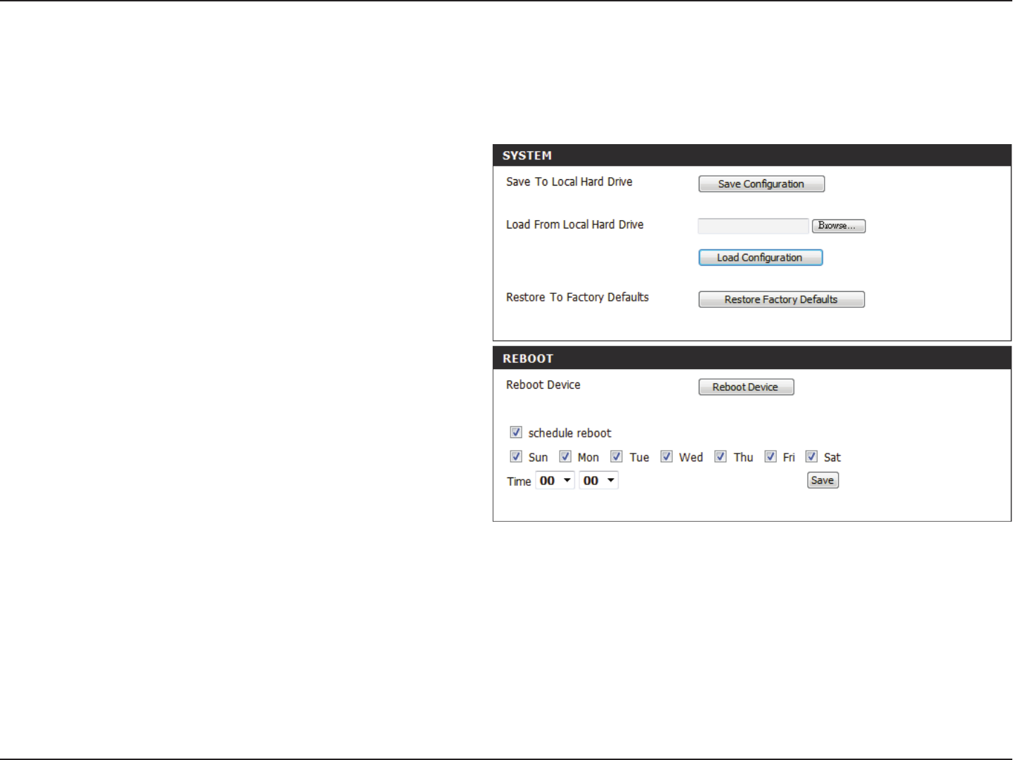
System
Click on the Save Conguration button to
save the current conguration to your hard
drive.
To load a saved conguration, click on the
Browse button to select a conguration le
from your hard drive. Then, click the Load
Configuration button to load the new
conguration.
Click this button to reset all settings to their
factory defaults. If you select to reset your
settings, you will need to set up your camera
again.
Select this option to schedule a time for the
device to reboot.
Clicking the Reboot button will reboot your
device.
After making any changes, click the Save button
to save your changes.
This screen allows you to save and restore the camera’s current conguration. You can also reset all settings to the factory default or reboot the device.
Save to Local
Hard Drive:
Load from Local
Hard Drive:
Restore
to Factory
Defaults:
Schedule
Reboot:
Reboot Device:
59D-Link DCS-5222LB1 User Manual
Section 4 - Conguration
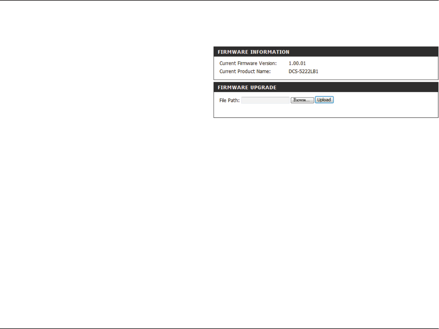
Firmware Upgrade
To upgrade your rmware, go to support.dlink.com and download
the latest rmware to your computer’s hard drive.
Click on Browse, select the rmware le, then click the Upload
button.
While the rmware is being upgraded, do not turn o your computer
or camera, and do not disconnect your network connection from your
computer or camera. Upgrading the rmware will not change any
of your system settings, but it is recommended that you save your
system conguration before doing a rmware upgrade.
Note: It is recommended that you use a wired connection for your
computer and camera when upgrading the rmware.
Your current rmware version and date will be displayed on this page. You can also upgrade your rmware with a new version.
60D-Link DCS-5222LB1 User Manual
Section 4 - Conguration
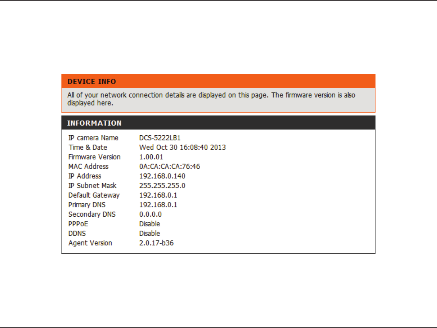
Status
This screen displays various information about your camera and its current settings.
Device Info
61D-Link DCS-5222LB1 User Manual
Section 4 - Conguration
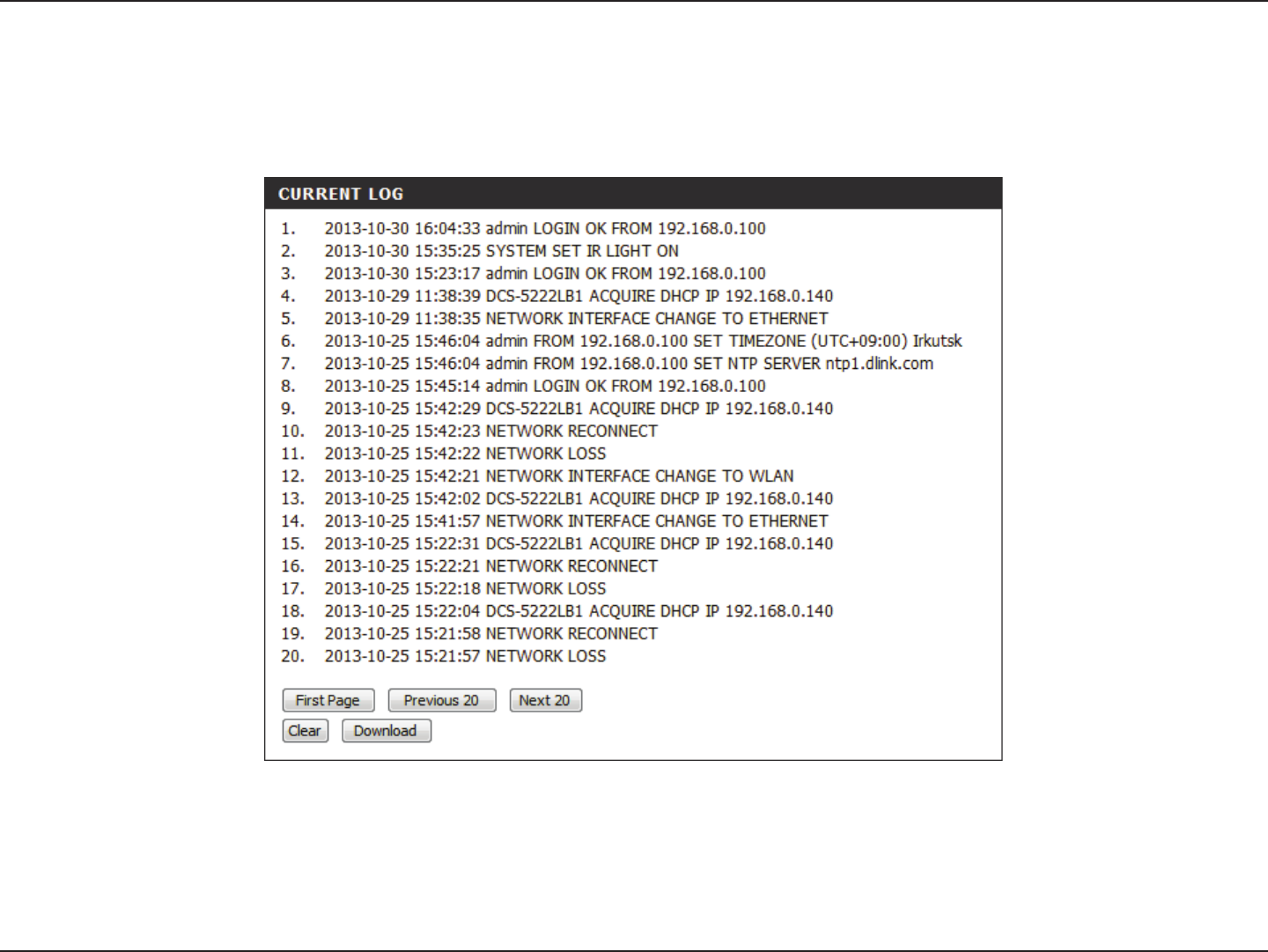
The log shows you a list of events that have happened recently. You can download the log by clicking the Download button, or you can empty the
log by clicking the Clear button.
Log
62D-Link DCS-5222LB1 User Manual
Section 4 - Conguration
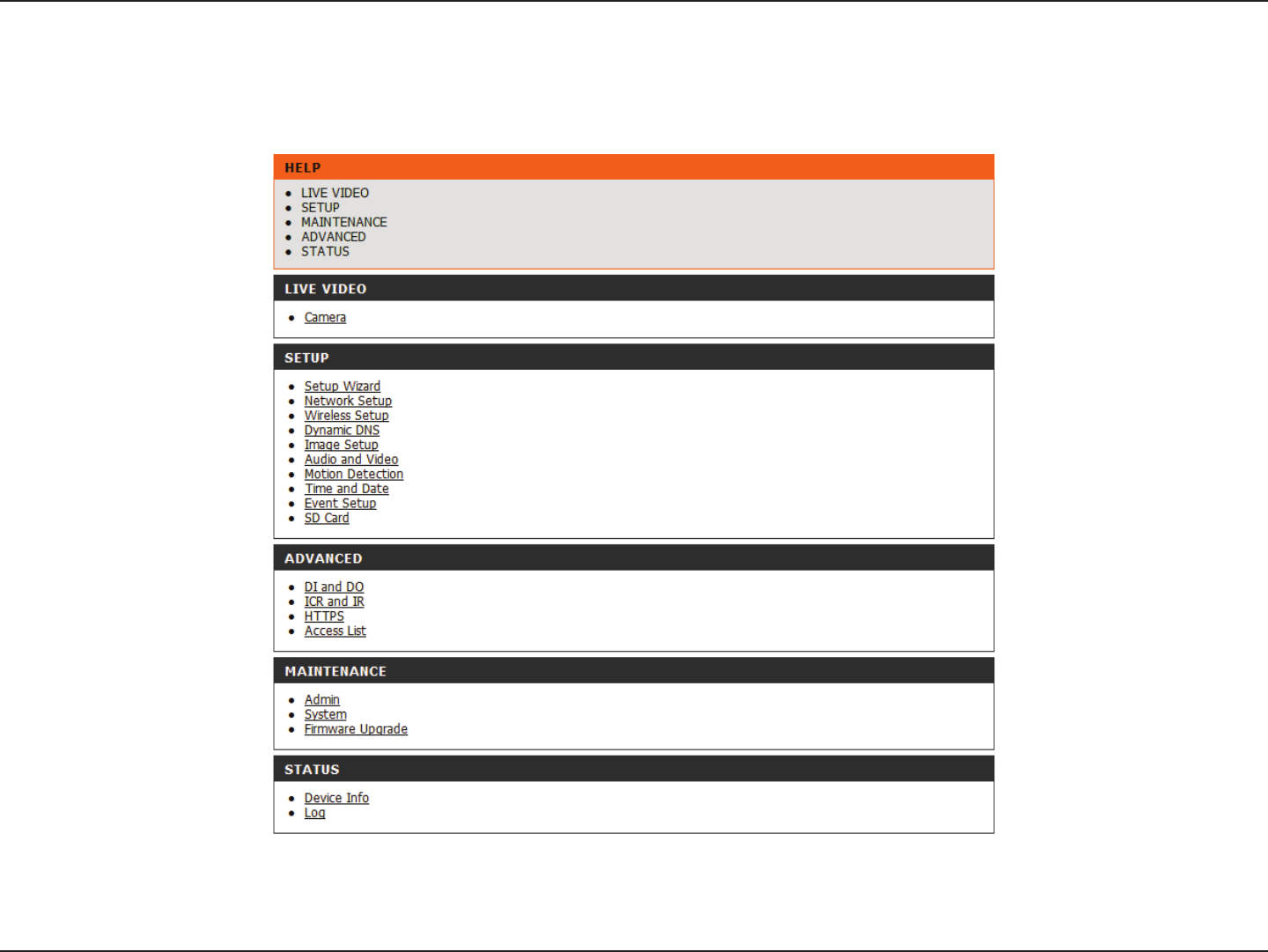
Help
Online help is available at any time by clicking on the Help tab.

63D-Link DCS-5222LB1 User Manual
Section 5 - Security
D-Link’s DCS-5222LB1 is a versatile and cost eective network camera oering both video and audio monitoring. It can also serve as a powerful
surveillance system in security applications. The DCS-5222LB1 can be used with any wired or 802.11n/g wireless router. This section explains how
to view the camera from either the Internet or from inside your internal network. This step is only needed if you do not wish to take advantage of
the built in mydlink functions.
Components Needed:
• 1 DCS-5222LB1 Network Camera
• 1 Ethernet Cable
• A wired or wireless router such as the D-Link DIR-655 Wireless Router
• Ethernet-based PC for system conguration
Setting up the DCS-5222LB1 for Use Behind a Router
Installing a DCS-5222LB1 Network Camera on your network is an easy 4–step procedure:
1. Assign a local IP address to your network camera.
2. View the network camera using your Internet Explorer web browser.
3. Access the router with your web browser.
4. Open virtual server ports to enable remote image viewing.
Note: These are manual steps; however, if you decide to use the wizard, it will perform every step automatically.
This section is designed to walk you through the setup process for installing your camera behind a router and enable remote video viewing. For
the basic setup of the DCS-5222LB1, follow the steps outlined in the Quick Installation Guide.
After you have completed the setup of the DCS-5222LB1 outlined in the Quick Installation Guide you will have an operating camera that has an
assigned IP Address. Because you are using a router to share the Internet with one or more PCs, the IP Address assigned to the network camera
will be a local IP Address. This allows viewing within your Local Area Network (LAN) until the router is congured to allow remote viewing of the
camera over the Internet.
Conguring the DCS-5222LB1 with a Router
64D-Link DCS-5222LB1 User Manual
Section 5 - Security
1. Assign a Local IP Address to Your Camera
Run the setup wizard from the CD included with the DCS-5222LB1. Follow the steps in the Quick Installation Guide to congure the DCS-5222LB1.
The camera will be assigned a local IP Address that allows it to be recognized by the router. Write down this IP Address for future reference.
Open a Web browser. In the address bar, type in the IP Address that was assigned to the network camera. The DCS-5222LB1 Live Video Page appears
with a window displaying live video from the camera.
Click on the Setup button on the left side. Scroll down the Network Setup page to nd the ports used by HTTP and Streaming audio and video.
2. View the network camera Using Your Internet Explorer Web Browser
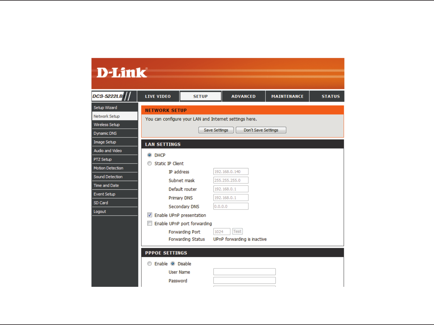
65D-Link DCS-5222LB1 User Manual
Section 5 - Security
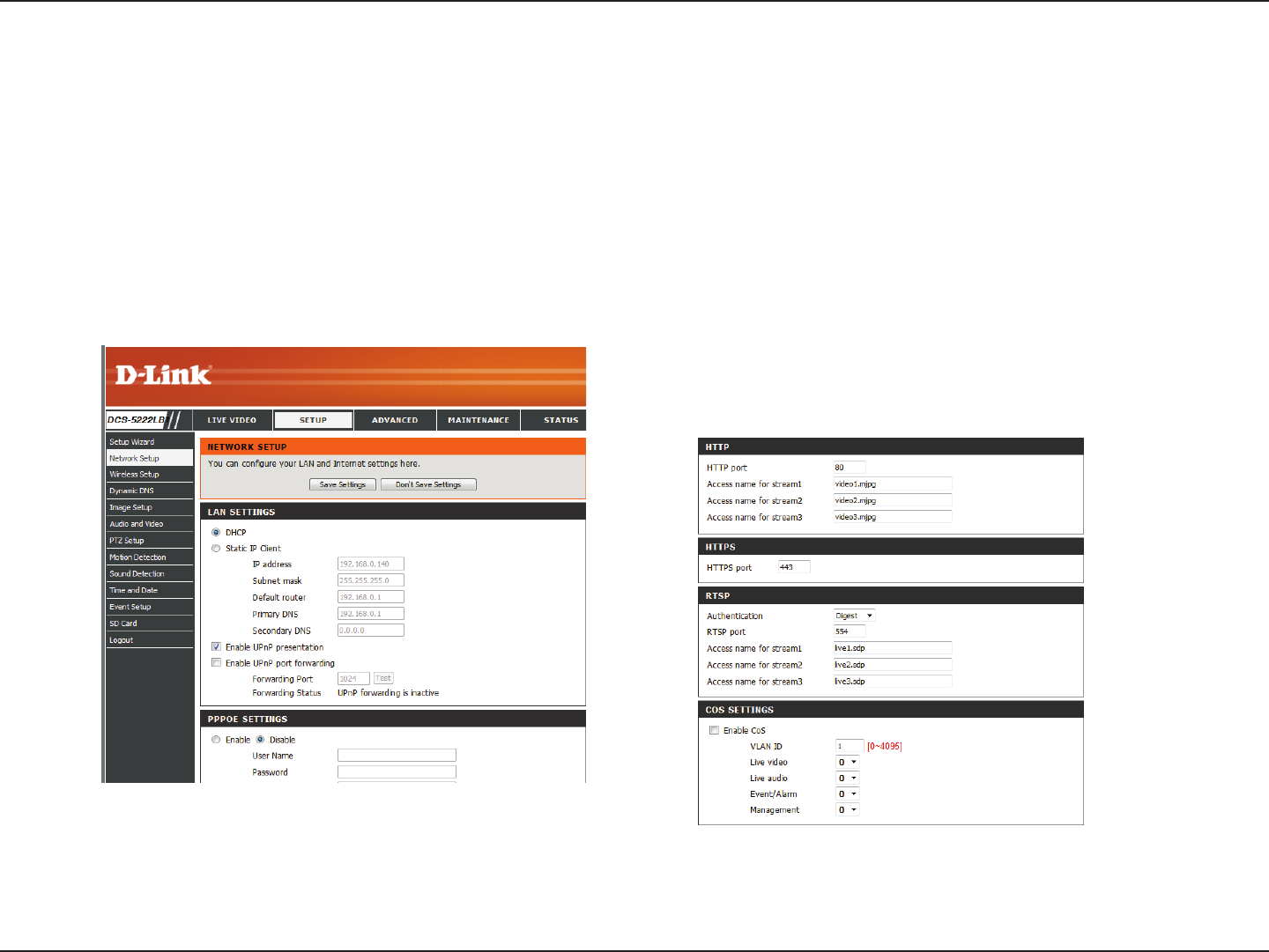
The Setup > Network page displays the port settings for your camera. If necessary, these ports can be changed if they are already in use by other
devices (e.g. in a multiple camera environment).
Note: Both the HTTP port and RTSP port are required to be opened for the DCS-5222LB1.
66D-Link DCS-5222LB1 User Manual
Section 5 - Security
The following steps generally apply to any router that you have on your network. The D-Link DIR-655 is used as an example to clarify the conguration
process. Refer to the router’s user manual for more information on router operation and conguration.
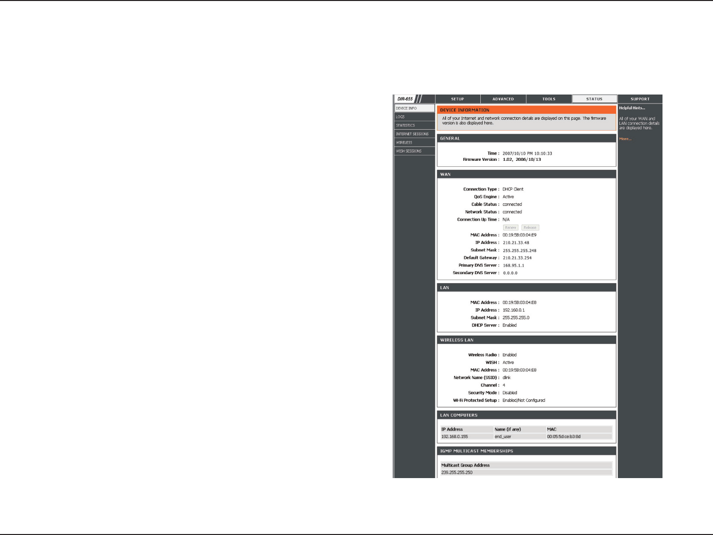
3. Access the Router with Your Web Browser
If you have cable or DSL Internet service, you will most likely have
a dynamically assigned WAN IP Address. ‘Dynamic’ means that your
router’s WAN IP address can change from time to time depending
on your ISP. A dynamic WAN IP Address identies your router on the
public network and allows it to access the Internet. To nd out what
your router’s WAN IP Address is, go to the Status page on your router
and locate the WAN information for your router (as shown on the next
page). The WAN IP Address will be listed. This will be the address that
you will need to type in your web browser to view your camera over
the Internet.
Router Set-Up and Installation
Your WAN IP Address will be listed on the router’s Status > Device
Info page.

67D-Link DCS-5222LB1 User Manual
Section 5 - Security
Note: Because a dynamic WAN IP can change from time to time depending on your ISP, you may want to obtain a Static IP address from your ISP. A Static
IP address is a xed IP address that will not change over time and will be more convenient for you to use to access your camera from a remote location. The
Static IP Address will also allow you to access your camera attached to your router over the Internet.
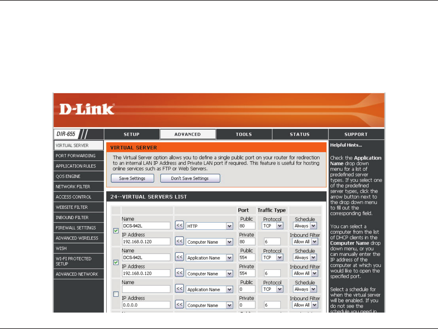
4. Open Ports to Enable Remote Image Viewing (Port Forwarding)
The rewall security features built into the DIR-655 router prevent users from accessing the video from the DCS-5222LB1 over the Internet. The
router connects to the Internet over a series of numbered ports. The ports normally used by the DCS-5222LB1 are blocked from access over the
Internet. Therefore, these ports need to be made accessible over the Internet. This is accomplished using the Virtual Server function on the DIR-655
router. The Virtual Server ports used by the camera must be opened through the router for remote access to your camera. Virtual Server is accessed
by clicking on the Advanced tab of the router screen.
1. Click Enabled.
2. Enter a dierent name for each entry.
3. Enter your camera’s local IP Address (e.g., 192.168.0.120) in the Private IP eld.
4. Select TCP for HTTP port, both (TCP and UDP) for RTSP and both (TCP and UDP) for 5556 - 5559 ports.
5. If you are using the default camera port settings, enter 80 into the Public and Private Port section, click Apply.
6. Scheduling should be set to Always so that the camera images can be accessed at any time.
Follow these steps to congure your router’s Virtual Server settings:
68D-Link DCS-5222LB1 User Manual
Section 5 - Security
Repeat the previous steps adding the port 554 to both the Public and Private Port sections. A check mark appearing before the entry name will
indicate that the ports are enabled.
Important: Some ISPs block access to port 80 and other commonly used Internet ports to conserve bandwidth. Check with your ISP so that you can
open the appropriate ports accordingly. If your ISP does not pass trac on port 80, you will need to change the port the camera uses from 80 to
something else, such as 8080. Not all routers are the same, so refer to your user manual for specic instructions on how to open ports.
Enter valid ports in the Virtual Server section of your router. Please make sure to check the box next to the camera name on the Virtual Server List
to enable your settings.

69D-Link DCS-5222LB1 User Manual
Section 6 - Troubleshooting
Troubleshooting
This chapter provides solutions to problems that can occur during the installation and operation of the DCS-5222LB1. Read the following descriptions
if you are having problems. (The examples below are illustrated in Windows Vista® and XP. If you have a dierent operating system, the screenshots
on your computer will look similar to the following examples.)
1. What is Remote Access? How do I enable it?
Remote Access allows you to access your camera from any PC connected to the Internet through a web browser. This lets you view your camera
feed and manage your camera’s settings when you’re away from home. To enable Remote Access, simply go through the Camera Installation Wizard
included on the Installation CD that came in your package. You can also download the wizard from the following websites:
DCS-5222LB1: http://DCS-5222LB1.mydlink.com
After going through the wizard, you should see Remote Status: Enabled on the summary page.
If you see Remote Status: Disabled, make sure that:
...the front LED on your camera is lit solid green
...your Internet connection is working
...your router’s LAN & WAN connections are working properly
...your router has UPnP enabled (if your router does not support UPnP, please refer to Appendix A)
...your router can get a public IP
...your router is upgraded to the latest rmware
...you have tried rebooting your router by unplugging it, then plugging it back in
After checking the above items, you can click the Retry button to refresh the summary screen to see if Remote Access has been enabled.
2. What can I do if I forget my password?
If you forget your password, you will need to perform a hard reset of your camera. This process will change all your settings back to the factory
defaults.
To reset your camera, please use an unfolded paperclip to press and hold the RESET button for at least 3 seconds while your camera is plugged in.

70D-Link DCS-5222LB1 User Manual
Section 6 - Troubleshooting
3. Why does the LED not light up?
The power supply might be faulty. Conrm that you are using the provided DC 5V power supply for this network camera. Verify that the power
supply is correctly connected. If the camera is functioning normally, the LED may have been disabled. See 第 56 第第第Admin第 for information about
how to enable the LED.
4. Why is the camera’s network connection unreliable?
There might be a problem with the network cable. To conrm that the cables are working, PING the address of a known device on the network. If
the cabling is OK and your network is reachable, you should receive a reply.
Another possible problem may be that the network device such as a hub or switch utilized by the network camera is not functioning properly.
Please conrm the power for the devices are well connected and functioning properly.
5. Why does the network camera work locally but not remotely?
This might be caused by a routers rewall protection. Check the Internet rewall with your system administrator. The rewall may need to have
some settings changed in order for the network camera to be accessible outside your local LAN. For more information, please refer to the section
about installing your camera behind a router.
Make sure that the network camera isn’t conicting with any Web server you may have running on your network.
The default router setting might be a possible reason. Check that the conguration of the router settings allow the network camera to be accessed
outside your local LAN.
6. Why does a series of broad vertical white lines appear through out the image?
It could be that the CMOS sensor (a square panel situated behind the lens that measures the light signals and changes it into a digital format so
your computer can present it into an image that you are familiar with) has become overloaded when it has been exposed to bright lights such as
direct exposure to sunlight or halogen lights. Reposition the network camera into a more shaded area immediately as prolonged exposure to bright
lights will damage the CMOS sensor.
7. The camera is producing noisy images. How can I solve the problem?
The video images might be noisy if the network camera is used in a very low light environments.

71D-Link DCS-5222LB1 User Manual
Section 6 - Troubleshooting
8. The images are poor quality, how can I improve the image quality?
Make sure that your computer’s display properties are set to at least 6-bit color. Using 16 or 256 colors on your computer will produce dithering
artifacts in the image, making the image look as if it is of poor quality.
The conguration on the network camera image display is incorrect. The Web Conguration Video section of the Web management allows you to
adjust the related-parameters for improved images such as: brightness, contrast, hue and light frequency. Please refer to the Web Conguration
section for detailed information.
9. Why are no images available through the Web browser?
ActiveX might be disabled. If you are viewing the images from Internet Explorer make sure ActiveX has been enabled in the Internet Options menu.
You may also need to change the security settings on your browser to allow the ActiveX plug-in to be installed.
If you are using Internet Explorer with a version number lower than 6, then you will need to upgrade your Web browser software in order to view
the streaming video transmitted by the network camera.
If you are using another browser such as Google’s Chrome or Apple’s Safari, you may need to install the appropriate plugin before the streaming
video will work.
If you are using Java, you may need to update to the latest version of the Java application. Please visit Sun’s website in order to obtain the newest
version Java for your computer platform (http://www.java.com).
You browser may also have 3rd party applications blocked. Please make sure that the browser you are using does not have 3rd party plugin support
disabled. You may need to refer to your particular browsers help function in order to turn this functionality on or o.
10. The PIR is not operating well, how can I improve the PIR quality?
- For the Passive Infrared Sensor (PIR) to function properly it is required to have direct line of site to the object. When
the room has many obstacles or the line of site is obstructed by glass, the PIR will not function properly.
- When the environment temperature is too high, the PIR detection will slow down and should not be mistaken for a faulty PIR.
- This network camera can only be installed indoors. Do not install this camera in a place where IR interference can be a problem. IR
interference can be found close to glass doors or windows, where direct sunlight can cause interference or in the path of car headlights.
- Do not install this camera next to or in front of an air conditioner outlet or vent.
- Do not install this camera close to wireless devices with high frequencies as the PIR is easily aected by RF radiation.

72D-Link DCS-5222LB1 User Manual
Section 6 - Troubleshooting
- The PIR functions at best when detecting lateral movements. Radial movements cannot be detected as well as lateral movements.
- Do not install this camera directly under an extreme bright light. The PIR cannot fully suppress a bright white light.
- Any movements from an object with a normal body temperature, like humans or animals, can be
detected. To avoid any malfunctions, install this camera at the proper height.
- To avoid any malfunctions, install this camera in an environment with an average temperature of 25°C. Only within
a distance of 2.5 meters can smaller movements of an object, with the average adult human’s height, be detected.
Between a distance of 2.5 and 5 meters, a larger movement of an object is required for detection.
- Install this camera on a rm, static, anti-shock surface.
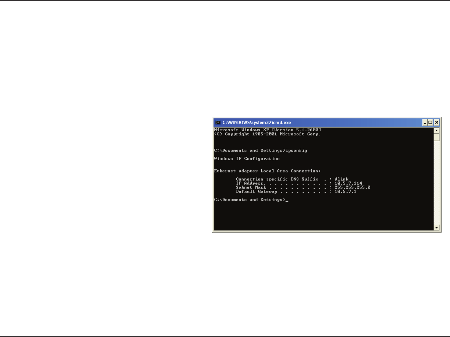
73D-Link DCS-5222LB1 User Manual
Appendix A - Networking Basics
Networking Basics
Check your IP address
By default, the TCP/IP settings should be set to obtain an IP address from a DHCP server (i.e. wireless router) automatically. To verify your IP address,
please follow the steps below.
Click on Start > Run. In the run box type cmd and click OK. (Windows® 7/Vista® users type cmd in the Start Search box)
At the prompt, type ipcong and press Enter.
This will display the IP address, subnet mask, and the default
gateway of your adapter.
If the address is 0.0.0.0, check your adapter installation, security
settings, and the settings on your router. Some rewall software
programs may block a DHCP request.
If you are connecting to a wireless network at a hotspot (e.g.
hotel, coee shop, airport), please contact an employee or
administrator to verify their wireless network settings.
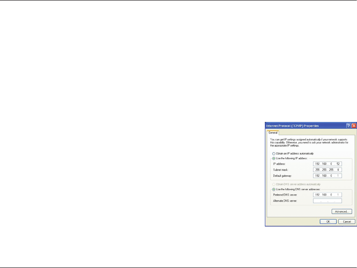
74D-Link DCS-5222LB1 User Manual
Appendix A - Networking Basics
Statically Assign an IP Address
If you are not using a DHCP capable gateway/router, or you need to assign a static IP address, please follow the steps below:
Step 1
Windows® 7- Click on Start > Control Panel > Network and Internet > Network and Sharing Center.
Windows® Vista - Click on Start > Control Panel > Network and Internet > Network and Sharing Center > Manage Network Connections.
Windows XP - Click on Start > Control Panel > Network Connections.
Step 2
Right-click on the Local Area Connection which represents your D-Link network adapter and select Properties.
Step 3
Highlight Internet Protocol (TCP/IP) and click Properties.
Step 4
Click Use the following IP address and enter an IP address that is on the same subnet as your network or
the LAN IP address on your router.
Example: If the router´s LAN IP address is 192.168.0.1, make your IP address 192.168.0.X where X is a
number between 2 and 99. Make sure that the number you choose is not in use on the network. Set Default
Gateway to the same as the LAN IP address of your router (192.168.0.1).
Set Primary DNS to the same as the LAN IP address of your router (192.168.0.1). The Secondary DNS is not
needed or you may enter a DNS server from your ISP.
Step 5
Click OK twice to save your settings.
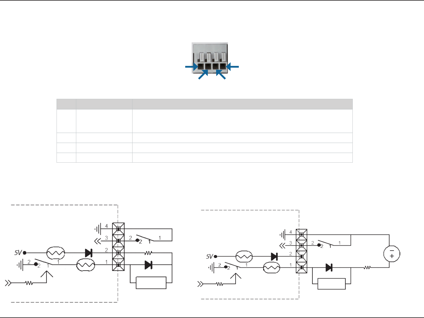
75D-Link DCS-5222LB1 User Manual
Appendix A: DI/DO Specications
DI/DO Specications
Pin 1 Pin 4
Pin 3Pin 2
Internal 5V Power External 3~12V Power
DI Input
DO Output
GPIO
PTC 1
PTC 2
DI Input
DO Output
GPIO
PTC 1
PTC 2
DC3 V ~ 12V
PIN FUNCTION NOTE
1 Digital Out (DO) Uses an open-drain NFET transistor with the source connected to GND in camera. If used
with an external relay, a diode must be connected in parallel with the load for protec-
tion against voltage transients. Max loading is 100 mA.
2 DC5V OUTPUT DC 5 V Output / Max. 100 mA
3 Digital In (DI) A switch from DI to GND, activated by setting NO. or NC.
4 GND GND

76D-Link DCS-5222LB1 User Manual
Appendix A - Technical Specications
Technical Specications
General Specications
Camera Specifications • 1/4” Megapixel Progressive CMOS sensor
• 5 meter IR illumination distance
• Minimum illumination 0 lux with IR LED on
• Built-in Infrared-Cut Removable (ICR) Filter module
• Focal length 3.6 mm
• Aperture: F2
• Exposure Time: 1/7.5 sec. to 1/10,000 sec.
• Angle of view:
• (H) 70°
• (V) 53°
• (D) 92°
• Built-in Microphone
Video Features • Configurable image size, quality, frame rate, and bit rate
• Time stamp and text overlays
• Configurable motion detection windows
• Configurable shutter speed, brightness, saturation, contrast, mirror, flip
Video Compression • H.264/MPEG4/MJPEG format simultaneous
compression
• H.264/MPEG4 multicast streaming
• JPEG for still images
Video Resolution • 16:9 (supports frame rates up to 30 fps)
• 1280 x 720
• 800 x 450
• 640 x 360
• 480 x 270
• 320 x 176 at 30 fps
• Others (supports frame rates up to 30 fps)
• 1024 x 768
• 800 x 600
• 640 x 480
• 480 x 360
• 320 x 240
Pan/Tilt/Zoom • Pan Range: -170° to 170°
• Tilt Range: -20° to 100°
• Digital Zoom: 10x
• Manual Pan Speed: 5-80 ° per second
• Manual Tilt Speed: 5-80 ° per second
• Position Presets: 32 points
Audio Compression • G.711
• G.726
• AAC
Network Protocol Support • IPv4/IPv6
• ARP
• TCP
• UDP
• ICMP
• QoS
• DHCP Client
• NTP Client (D-Link)
• DNS Client
• DDNS Client (D-Link)
• SMTP Client
• FTP Client
• HTTP Server
• PPPoE
• RTP
• RTSP
• RTCP
• 3GPP
Network Interface • IEEE 802.11n • 10/100 BASE-TX Fast Ethernet
External Device Interface • MicroSD/SDHC Slot
3
• Audio Output
• DI/DO Port

77D-Link DCS-5222LB1 User Manual
Appendix A - Technical Specications
Advanced Features
Remote Management • Take snapshots/video clips and save to local hard drive
via web browser
• Configuration accessible via web browser
Security • Administrator and user group protected
• Password authentication
• HTTP and RTSP digest encryption
Surveillance • Record video continuously
• Record video according to a weekly schedule
• Record video when motion is detected
• Upload snapshots/video clips via e-mail
• Upload snapshots/video clips via FTP
Mobile App Support • mydlink Lite app for iOS and Android devices
System Requirements
Operating System • Microsoft Windows 8/7/Vista/XP SP3
Compatible Browsers • Microsoft Internet Explorer 8, Firefox 12, Chrome 20,
Safari 4 or above, or other Java-enabled browser
Supported Mobile Devices • Mobile devices with a 3GPP player, such as Packet Video
Player 3.0, QuickTime 6.5, or Real Player 10.5
• mydlink™ app requires a mobile device running iOS or Android
Physical
Dimensions • 120 x 103.2 x 130 mm (4.72 x 4.06 x 5.11 inches)
Weight • 340 grams (0.75 lb)
Power Input • Input: 12 V/1.25 A, 50/60 Hz
Temperature • Operating: 0 to 40 °C (32 to 104 °F) • Storage: -20 to 70 ºC (-4 to 158 ºF)
Humidity • Operating: 20% to 80% non-condensing
Certifications • CE
• FCC Class B
• C-Tick
• CE LVD
3 An SDHC Class 6 card or above is recommended. Card capacities of up to 32GB supported.
FCC Notices
This device complies with Part 15 of the FCC Rules. Operation is subject to the following
two conditions: (1) this device may not cause harmful interference, and (2) this device
must accept any interference received, including interference that may cause undesired
operation.
CAUTION: Change or modification not expressly approved by the party responsible
for compliance could void the user’s authority to operate this equipment.
This equipment has been tested and found to comply with the limits for a Class B
digital device, pursuant to Part 15 of the FCC Rules. These limits are designed to provide
reasonable protection against harmful interference in a residential installation. This
equipment generates, uses and can radiate radio frequency energy and, if not installed
and used in accordance with the instructions, may cause harmful interference to radio
communications. However, there is no guarantee that interference will not occur in a
particular installation. If this equipment does cause harmful interference to radio or
television reception, which can be determined by turning the equipment off and on, the
user is encouraged to try to correct the interference by one or more of the following
measures:
--Reorient or relocate the receiving antenna.
--Increase the separation between the equipment and receiver.
--Connect the equipment into an outlet on a circuit different from that to which the receiver
is connected.
--Consult the dealer or an experienced radio/TV technician for help.
CAUTION:
Any changes or modifications not expressly approved by the grantee of this device could
void the user's authority to operate the equipment.
RF exposure warning
This equipment must be installed and operated in accordance with provided instructions
and the antenna(s) used for this transmitter must be installed to provide a separation
distance of at least 20 cm from all persons and must not be co-located or operating in
conjunction with any other antenna or transmitter. End-users and installers must be
provide with antenna installation instructions and transmitter operating conditions for
satisfying RF exposure compliance."
Canada Notices
Industry Canada regulatory information
This device complies with Industry Canada licence-exempt RSS standard(s).
Operation is subject to the following two conditions: (1) this device may not cause
interference, and (2) this device must accept any interference, including interference
that may cause undesired operation of the device.
The user is cautioned that this device should be used only as specified within this
manual to meet RF exposure requirements. Use of this device in a manner
inconsistent with this manual could lead to excessive RF exposure conditions.
Le présent appareil est conforme aux CNR d'Industrie Canada
applicables aux appareils radio exempts de licence. L'exploitation est
autorisée aux deux conditions suivantes : (1) l'appareil ne doit pas
produire de brouillage, et (2) l'utilisateur de l'appareil doit accepter tout
brouillage radioélectrique subi, même si le brouillage est susceptible
d'en compromettre le fonctionnement.
RF exposure warning
This equipment must be installed and operated in accordance with
provided instructions and the antenna(s) used for this transmitter must
be installed to provide a separation distance of at least 20 cm from all
persons and must not be co-located or operating in conjunction with any
other antenna or transmitter. End-users and installers must be provide
with antenna installation instructions and transmitter operating
conditions for satisfying RF exposure compliance."
Cet équipement doit être installé et utilisé conformément aux
instructions fournies et de l'antenne (s) utilisé pour cet émetteur doit être
installé pour fournir une distance de séparation d'au moins 20 cm de
toute personne et ne doit pas être co-localisés ou fonctionnant en
conjonction avec une autre antenne ou transmetteur. Les utilisateurs
finaux et installateurs doivent être fournir des instructions d'installation
de l'antenne et des conditions de fonctionnement du transmetteur de la
conformité sur l'exposition aux RF