D Link D1624VC1 2.4 GHz Wireless Broadband Router User Manual DI 624 010603 pmd
D Link Corporation 2.4 GHz Wireless Broadband Router DI 624 010603 pmd
D Link >
Contents
- 1. Users Manual 1
- 2. Users Manual 2
- 3. Users Manual 3
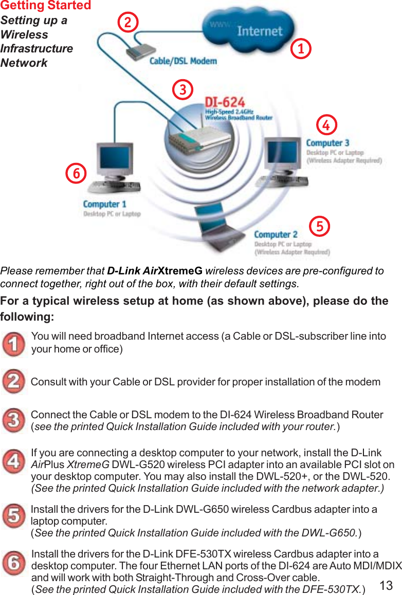
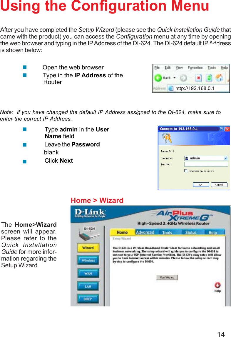
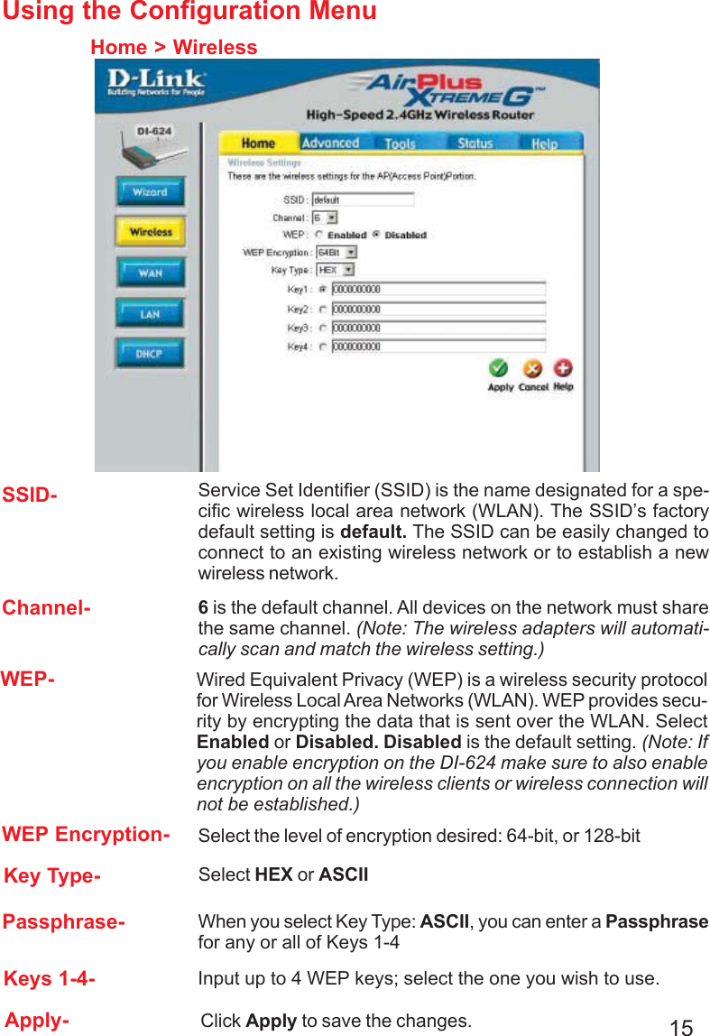
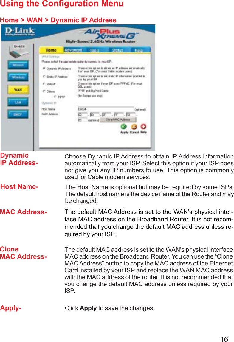
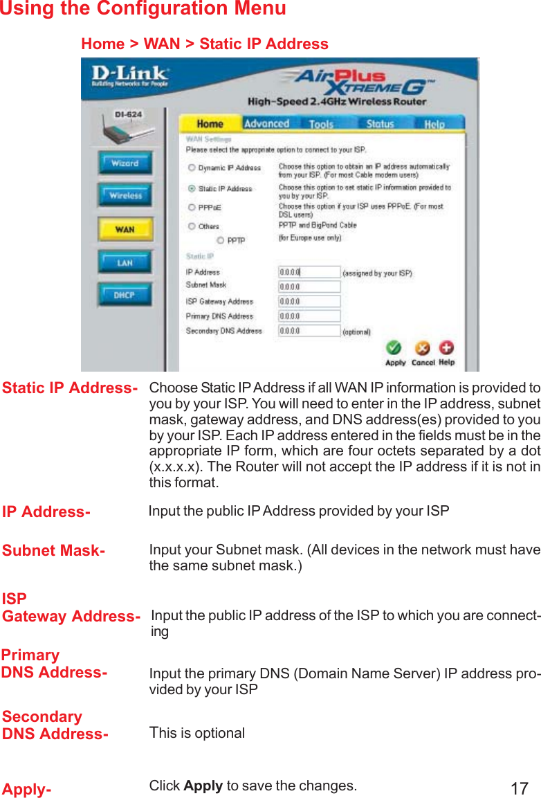
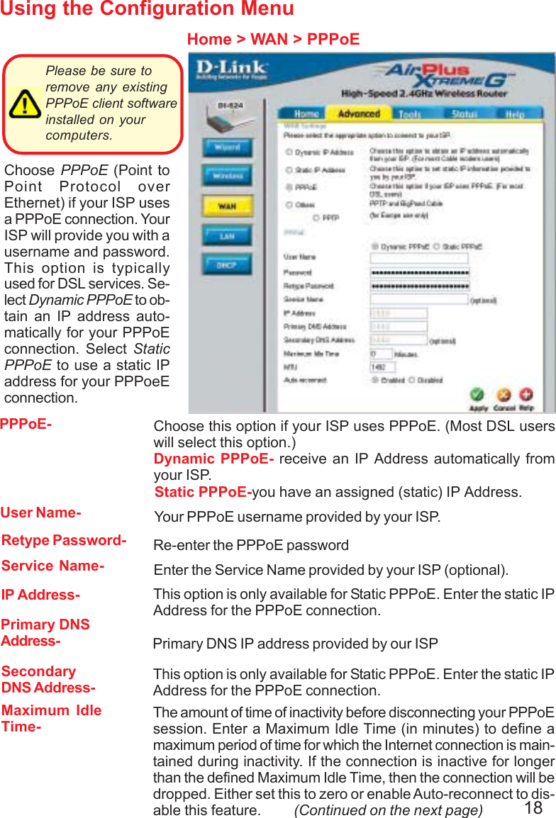
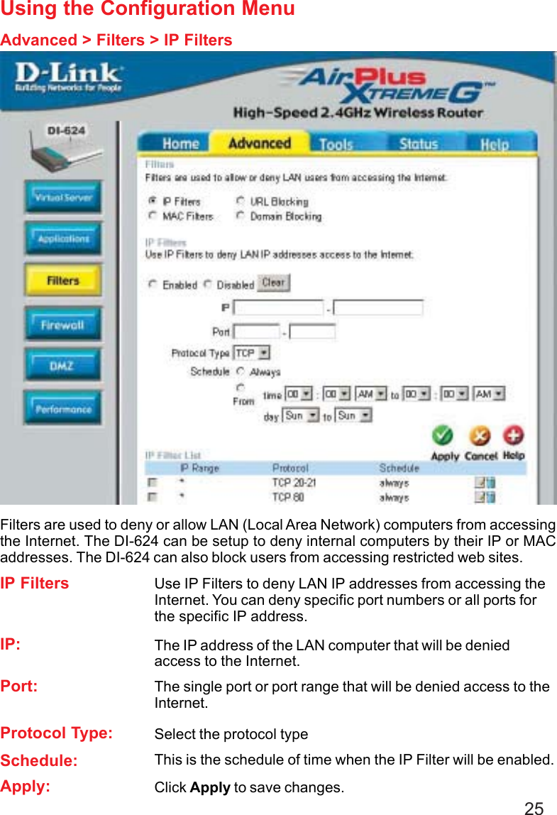
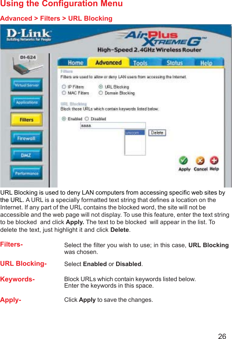
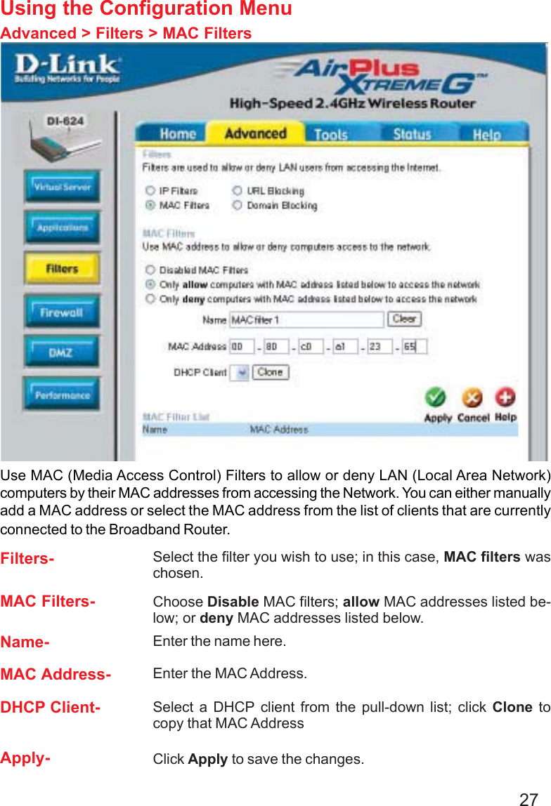
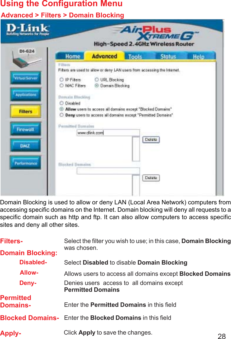
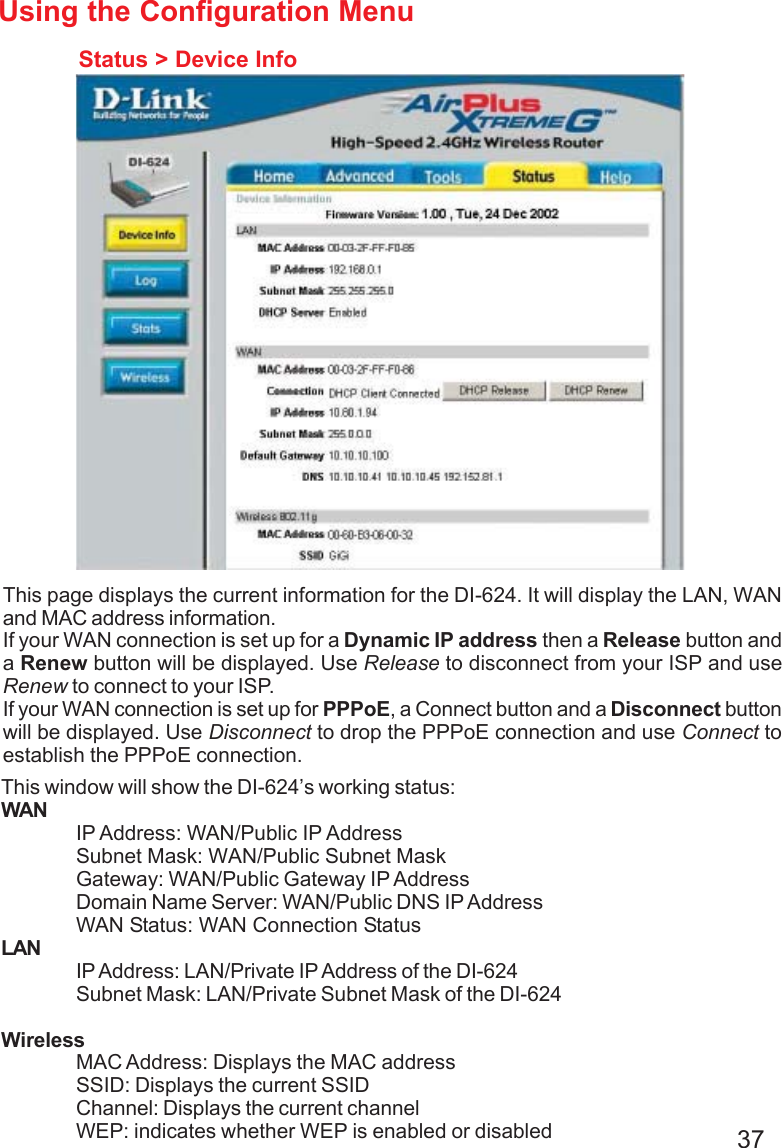
Users Manual 1