D Link DAP3760A1 Long Distance Wireless Outdoor Bridge User Manual Usermanual 090513
D Link Corporation Long Distance Wireless Outdoor Bridge Usermanual 090513
D Link >
Manual

DAP-3760 / DAP-3860
Broadband Wireless Access ODU
Quick Installation Guide

Copyright
Copyright © 2008 all rights reserved. No part of this publication may be reproduced, adapted,
stored in a retrieval system, translated into any language, or transmitted in any form or by any
means without the written permission of the supplier.
About the Installation Guide
This Installation Guide is intended to guide professional installer to install the wireless bridge. It
includes procedures assisting you in avoiding unforeseen problems.
Conventions
This indicates a warning or caution that you have to abide to avoid hazards.
This indicates an important note that you must pay attention to.
Note:
Warning:

Federal Communication Commission Interference Statement
This equipment has been tested and found to comply with the limits for a Class B digital device,
pursuant to Part 15 of the FCC Rules. These limits are designed to provide reasonable
protection against harmful interference in a residential installation. This equipment generates,
uses and can radiate radio frequency energy and, if not installed and used in accordance with
the instructions, may cause harmful interference to radio communications. However, there is
no guarantee that interference will not occur in a particular installation. If this equipment does
cause harmful interference to radio or television reception, which can be determined by turning
the equipment off and on, the user is encouraged to try to correct the interference by one of the
following measures:
- Reorient or relocate the receiving antenna.
- Increase the separation between the equipment and receiver.
- Connect the equipment into an outlet on a circuit different from that
to which the receiver is connected.
- Consult the dealer or an experienced radio/TV technician for help.
This device complies with Part 15 of the FCC Rules. Operation is subject to the following two
conditions: (1) This device may not cause harmful interference, and (2) this device must
accept any interference received, including interference that may cause undesired operation.
FCC Caution: Any changes or modifications not expressly approved by the party responsible
for compliance could void the user's authority to operate this equipment.
IMPORTANT NOTE:
FCC Radiation Exposure Statement:
This equipment complies with FCC radiation exposure limits set forth for an
uncontrolled environment. This equipment should be installed and operated
with minimum distance 100cm between the radiator & your body.

This transmitter must not be co-located or operating in conjunction with any other antenna or
transmitter.
The availability of some specific channels and/or operational frequency bands are country
dependent and are firmware programmed at the factory to match the intended destination. The
firmware setting is not accessible by the end user.
Professional Installation Required
1. Please seek assistance from a professional installer who is well trained in the RF
installation and knowledgeable in the local regulations.
2. The DAP-3760 / DAP-3860 is distributed through distributor and system installer with
professional technicians and will not be sold directly through retail store.
3. Product is for Point to Point operation only and cannot be use for Point to Multipoint
operation.

TABLE OF CONTENT
Professional Installation Required ...................................................................................................2
CHAPTER 1 INTRODUCTION...........................................................................................................5
INTRODUCTION......................................................................................................................................5
PRODUCT SPECIFICATION ......................................................................................................................6
TYPICAL APPLICATIONS.........................................................................................................................8
Tele-medical Broadband Wireless Application .................................................................................8
Campus Broadband Wireless Application.........................................................................................9
CHAPTER 2 PREPARATION BEFORE INSTALLATION............................................................10
SAFETY PRECAUTIONS ........................................................................................................................10
PRODUCT PACKETS..............................................................................................................................10
Mounting Kit................................................................................................................................... 11
Waterproof RJ-45 Connector Kit....................................................................................................11
SITE PLANNING ...................................................................................................................................12
Choosing a Mounting Location......................................................................................................12
Antenna Polarization......................................................................................................................13
CHAPTER 3 HARDWARE INSTALLATION..................................................................................14
ASSEMBLE THE MOUNTING BRACKET.................................................................................................14
POLE MOUNTING.................................................................................................................................15
INTERFACE DEFINITION .......................................................................................................................16
RS-232 ............................................................................................................................................16
Connect Up.....................................................................................................................................18
Grounding.......................................................................................................................................19
POWER ON...........................................................................................................................................19
ALIGN ANTENNA.................................................................................................................................21
CHAPTER 4 CONFIGURATION......................................................................................................23
CONNECT THE BRIDGE TO A LOCAL COMPUTER ..................................................................................23

BASIC SETTINGS..................................................................................................................................24
IP Address.......................................................................................................................................25
Operating Mode..............................................................................................................................25
Base Station ID...............................................................................................................................28
Output Power .................................................................................................................................28
Channel/Frequency.........................................................................................................................28
ADVANCED SETTINGS..........................................................................................................................28
Super Mode.....................................................................................................................................28
Security Settings .............................................................................................................................28
CHAPTER 5 TROUBLESHOOTING ...............................................................................................31
CHAPTER 6 TECHNICAL SUPPORT .............................................................................................32

Chapter 1 Introduction Page 5
Chapter 1 Introduction
Introduction
The DAP-3760 / DAP-3860 Wireless Bridge is a high-performance outdoor-deployable
wireless bridge that provides wireless connectivity among multiple network locations. Besides
the built-in 23dBi plane antennas, it can cover over 50km if with an external antenna co-used,
answering the demand of long distance backhaul with high throughput. Moreover, link
aggregation combines multiple links into one to enhance transmission rate; and network
backup ensures continuous transmission.
As a multi-function bridge, DAP-3760 / DAP-3860 supports Base Station, CPE and PTP
modes; among which, LANs in different locations and buildings could easily be connected and
access to broadband under PTP mode, realizing “Last Mile” Broadband.
With the high throughput and long-distance transmission, DAP-3760 / DAP-3860 is the ideal
backhaul solution for Carriers, Service Providers and Enterprises!

Chapter 1 Introduction Page 6
Product Specification
Specifications
CPU IXP425 ,533MHz
16MB Flash
System Memory 32MB SDRAM (64MB upgradable)
Power Power over Ethernet (Output 20Watts ,48V /0.4A)
Operating Frequency
FCC : 5.725~5.850 GHz
CE : 5.470~5.600 GHz, 5.650~5.725 GHz
(Programmable for different country regulations)
RF Modulation 802.11a: OFDM
(BPSK, QPSK, 16-QAm, 64QAM)
RF output power
24dBm (Max. of Avg.) at Radio for FCC (Band 4)
30 dBm EIRP for ETSI 301 893 (Band3)
(Controllable for different country regulations)
Sensitivity
≤-92dBm @6Mbps
≤-73dBm @54Mbps
Channel Spacing 40/20/10/5 MHz
FCC Part 15B
FCC Part 15C
ETSI 301 893
EN301 489-1/17
Regulation Compliance
EN60950
Features
Operation Mode Base Station , CPE, PtP, P2MP
Security WEP 64/128bits, WPA-PSK/WPA2-PSK, WPA/WPA-2
Radio Bandwidth Control 20MHz
Super A Fast Frames, Burst, Compression
TDM Coordination Traffic management
Intel® TDMA For long distance transmission
Distance in Meters Auto ACK-Time adjustment
Wireless Isolation YES
Management Statistics Wireless and Ethernet

Chapter 1 Introduction Page 7
Link Test Self-Wireless Connection test
Web-based Management (Secure SSL)
Command Line Interface (SSH or RS-232 (9600))
Configuration & Management
Windows-based Utility, SNMPv2
FW Upgrade Web/Windows management tool
Antenna
Gain 23dBi (Default for FCC)
Frequency Range 5400~5850 MHz
HPBW (horizontal) 10°
HPBW (vertical) 10°
Dimensions 320×320×18mm
Physical & Interface
Ethernet 10/100 Base T x1
Auto-sense, Negotiation
RS-232 YES
USB N/A
Buzzer Signal Indication
Reset Pin Reset system to factory default
Enclosure & Environment
External Antenna Connector N-Type
Enclosure
IP-67 (Die-Casting)
Level 7 Waterproof
Level 17 Beaufort Scale
Vent design
Antenna Flexibility
Mounting Pole Mount (ADC-12 Aluminum alloy)
Temperature -30 ~ 70 ℃, (Operating)
PCBA Dimensions 160 ×135 mm
Weight 2.4 Kg
Humidity 10~95%, (Operating)
Chapter 1 Introduction Page 8
Typical Applications
This section describes the typical applications centering on DAP-3760 / DAP-3860.
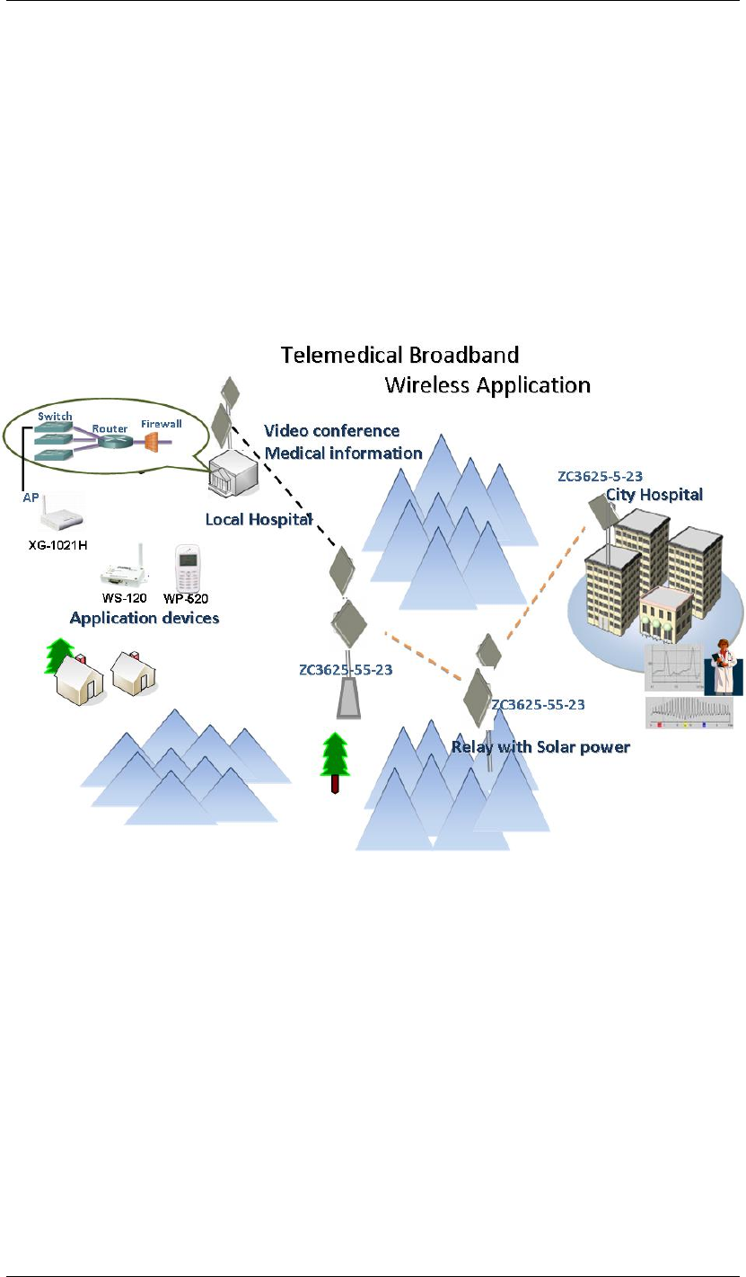
Tele-medical Broadband Wireless Application
DAP-3760 / DAP-3860 mainly plays as a relay with cost-effective solar power, sending medical
treatment information between city hospital and local hospital in rural area via broadband
wireless connectivity.
Chapter 1 Introduction Page 9
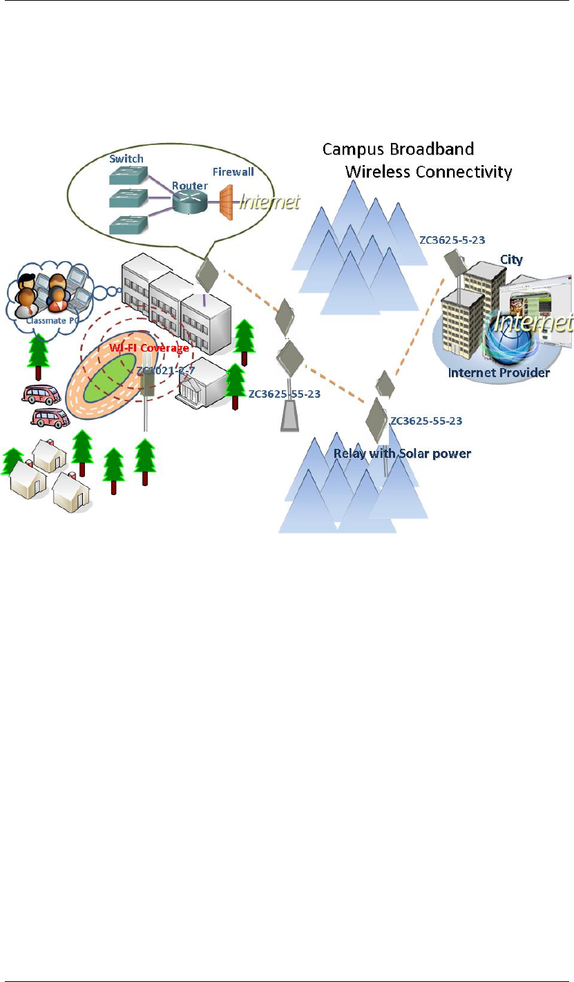
Campus Broadband Wireless Application
Campus in remote area can access to the Internet via broadband wireless connectivity
established by DAP-3760 / DAP-3860 which plays as relay and CPE.

Chapter 2 Preparation before Installation Page 10
Chapter 2 Preparation before
Installation
This chapter describes safety precautions and product information you have to know and
check before installing DAP-3760 / DAP-3860.
Safety Precautions
For your safety and proper installation, please read and follow the instructions below:
ONLY qualified service personnel should service or disassemble this device;
When installing the device, note the followings:
- Do NOT use a metal ladder;
- Do NOT work on a wet or windy day;
- Do NOT install, use or service the device during a thunderstorm, as this may cause
a remote risk of electric shock from lightning;
- Wear shoes with rubber soles and heels, rubber gloves, long sleeved shirt or jacket.
Ground the device properly with grounding wire to protect against power surges;
Use ONLY appropriate accessories for the device.
Product Packets
The product packets you have received should contain the following items, if any of them are
not included or damaged, please contact your local vendor for support.
DAP-3760 / DAP-3860 with integrated 23dBi antenna ×1
Mounting Kit ×1
PoE Injector & Power cord ×1
Grounding Wire ×1
Water Proof RJ-45 Connector Kit ×1
Product CD ×1
Chapter 2 Preparation before Installation Page 11
Product CD contains Management Tool, Quick Installation Guide and User
Manual!
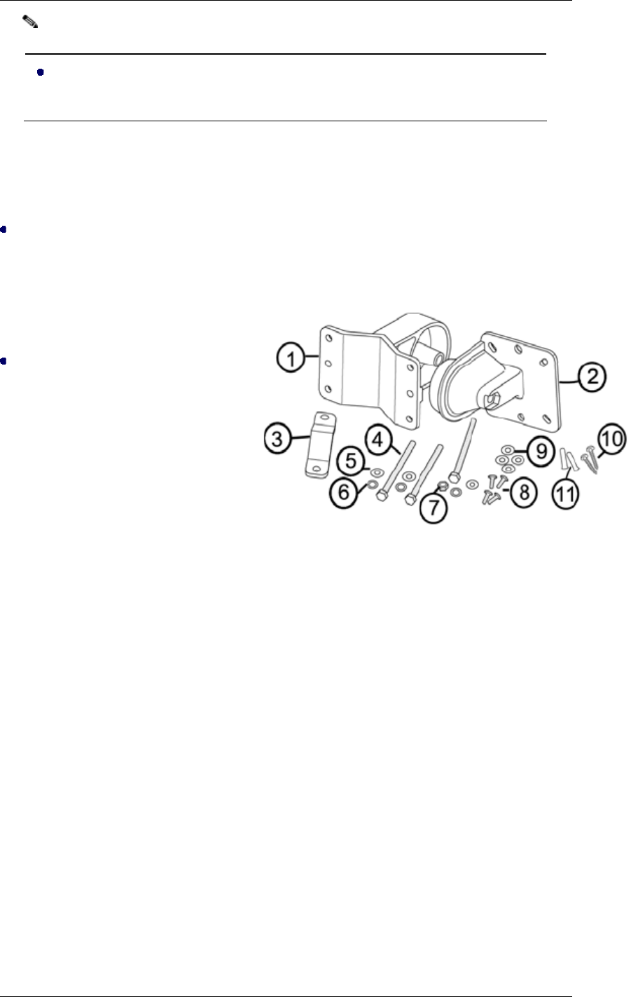
Mounting Kit
Wall/Pole Mounting Bracket
1. T-Form Bracket ×1
2. Articulation Pole ×1
3. Pole Mount Bar ×1
Fasteners
4. M8×110 Screw ×3
5. M8 Washer ×3
6. M8 Spring Washer ×3
7. M8 Nut ×1
8. M5×12 Screw ×4
9. M5 Washer ×4
10. Wood Screw ×4
11. Wall/Gyprock Plug ×4
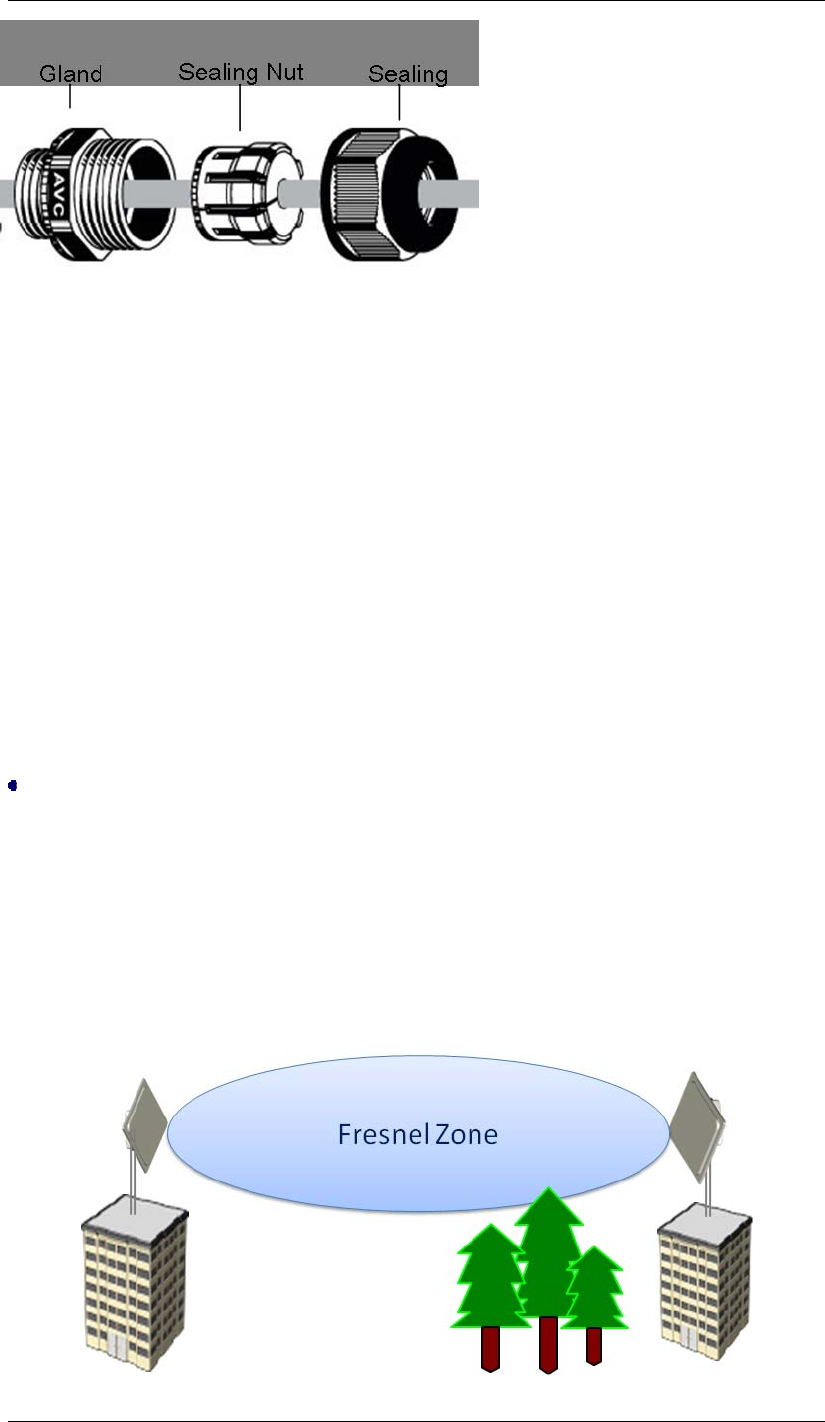
Waterproof RJ-45 Connector Kit
1. Gland ×1
2. Sealing Nut ×1
3. Sealing ×1
Note:
Chapter 2 Preparation before Installation Page 12
Site Planning
Prior to installation, develop a checklist that covers all aspects of the installation. A
well-developed plan identifies potential problems early so that they can be solved timely.
Choosing a Mounting Location
Choosing a good mounting location for the bridge is important because it affects the reliability
of the wireless link and maximum data rates the bridge system can achieve. The most
important considerations are distance between bridges and clearance from obstacles.
Signal path distance and clearance
In an environment without obstacles in the signal path, the maximum distance between
bridges depends primarily on the type of antennas and the free space loss between them.
Make sure your proposed mounting site is within range of the remote antenna.
Another consideration when planning a wireless link is the Fresnel Zone, which occupies a
series of concentric ellipsoid-shaped areas around the LoS path as below:

Chapter 2 Preparation before Installation Page 13
The Fresnel Zone is important to the wireless link as it defines an area around the LoS that can
introduce RF signal interference if blocked. Objects in the Fresnel Zone such as trees and
buildings can diffract or reflect the main signal away from the receiver, changing the RF LoS.
Antenna Polarization
The integrated antenna radiates and receives polarized radio signals. For the link to operate
correctly, two antennas at each end of the link must always be set for the same polarization,
either vertical or horizontal.
Professional Installation Required
Chapter 3 Hardware Installation Page 14
Chapter 3 Hardware Installation
The DAP-3760 / DAP-3860 Wireless Bridge is shipped with mounting hardware that
accommodates tower or mast installations. This chapter demonstrates the hardware
installation procedures, which include Assemble the Hardware Mounting, Pole Mounting,
Connect Up, Ground the Wire, Power On and Align the Antennas.
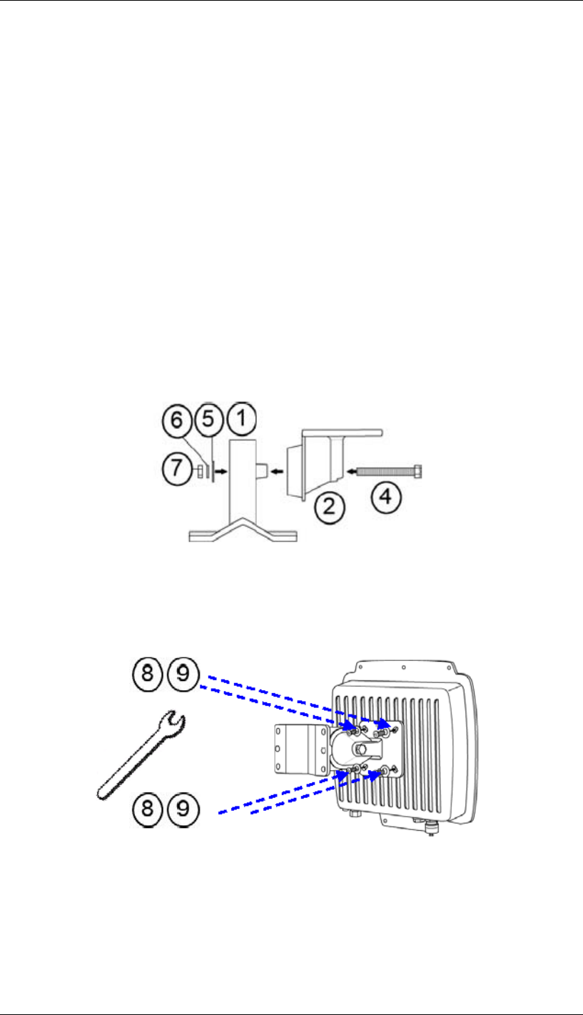
Assemble the Mounting Bracket
1. Assemble the main bracket by placing articulation pole to the T-form bracket via a
M8×110 screw through the insertion axe and fix with the M8 washer, spring washer and
M8 nut;
2. Place the main bracket into the seating and use a spanner to fasten the bracket to CPE
main unit with M5×12 screws and M5 washers provided in hardware packets;
Chapter 3 Hardware Installation Page 15
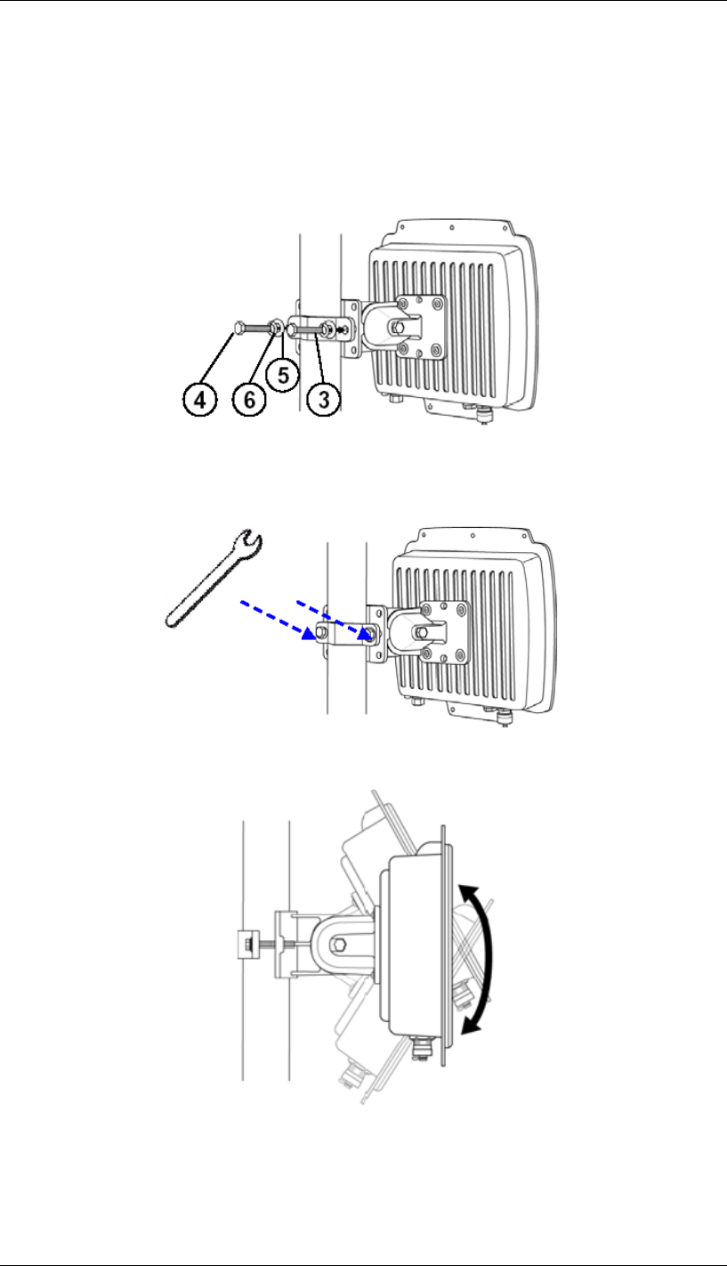
Pole Mounting
1. Install the main bracket and the pole mount bar over the top of the pole by securing the
drill holes of the pole mount bar to the main bracket ones and insert two M8×110 screws,
spring washers and washers through the drill holes and main bracket;
2. Fasten two M8×110 screws and washers through the drill holes and main bracket with a
spanner;
3. Adjust the antenna for appropriate tilt / vertical orientation.
Chapter 3 Hardware Installation Page 16
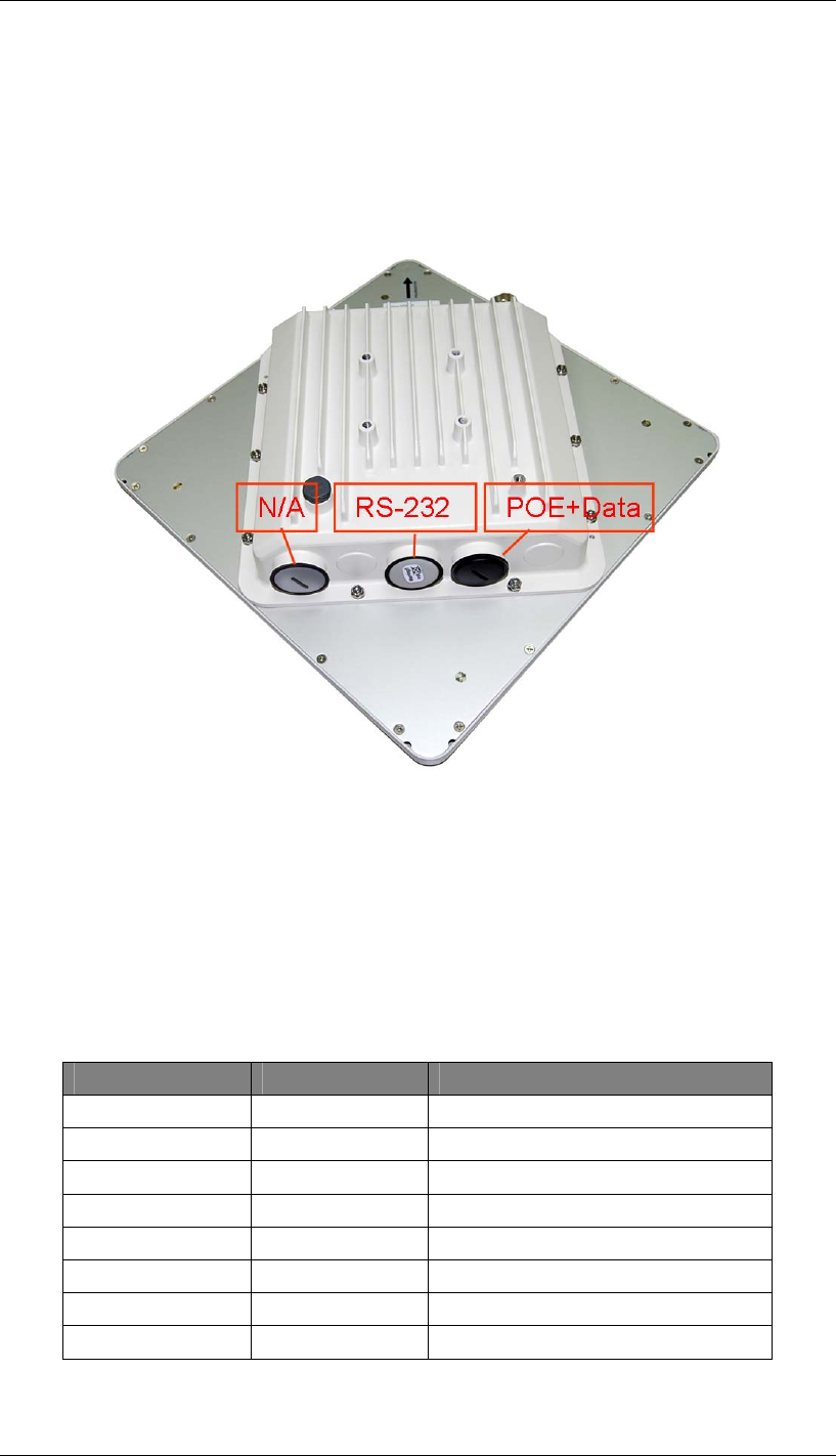
Interface Definition
DAP-3760 / DAP-3860 currently provides two interfaces at the bottom, which are PoE & Data
with a black plastic dummy cover and RS-232 with a white dummy cover. Among which, a
black RJ45 waterproof connector will be provided for the PoE & Data interface.
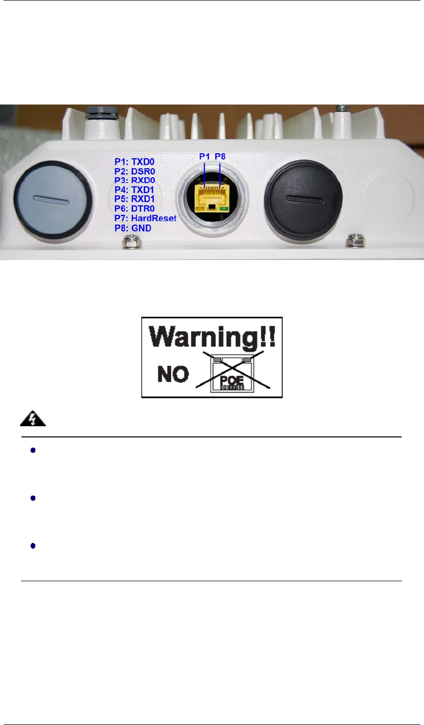
RS-232
RS-232 is used for debugging purposes as well as for hard reset of the DAP-3760 / DAP-3860.
Below you may find the pin definition of the RS-232.
PIN Definition:
Pin Assignment Name Description
P1 TXD0 Data Transmit 0
P2 DSR0 Data Set Ready 0
P3 RXD0 Data Receive 0
P4 TXD1 Data Transmit 1
P5 RXD1 Data Receive 1
P6 DTR1 Data Terminal Ready
P7 Hard Reset Hard reset the unit
P8 GND Ground
Chapter 3 Hardware Installation Page 17
To reset the device, short P7 (Hard Reset) to P8 (GND) for less than 1 second and the system
will reset. If P7 (Hard Reset) is shorted to P8 (GND) for over 5 seconds, the DAP-3760 /
DAP-3860 will be reset to the factory default settings.
Below are the views of RS-232 cover and RJ-45 port respectively, please note the label
covered on and DO strictly follow the instructions to avoid damaging your equipment!
Do NOT connect PoE cable to the RS-232 port; otherwise the port will
burnout!
If RS-232 cable is used outdoor, please DO add a surge protector to protect
the equipment circuit!
Strongly recommend to add a lightning arrestor on the RS-232 port to prevent
from lightning attack!
Warning:
Chapter 3 Hardware Installation Page 18
Connect Up
Before installing the Ethernet cable with a waterproof RJ-45 connector, it is recommended that
the Cat-5 RJ-45 coaxial cable be used for the DAP-3760 / DAP-3860 to power injector
connections.
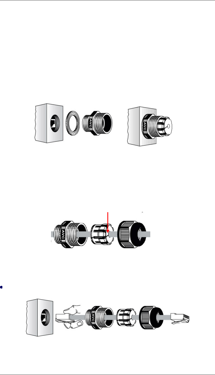
1. To connect to the hole labeled PoE+Data, open the black cover in advance by using a
coin or a slotted screwdriver and then screw in the body of the gland and tighten.
Connect Up – Step 1
2. Slide the sealing nut to the RJ-45 cable from its middle breach and then insert the sealing
into the cable.
Connect Up – Step 2
Insert the RJ-45 connector and make sure that the locking tab snaps home.
Connect Up – Step 3
Slide the Sealing Nut from its Breach
RJ-45 Port
Chapter 3 Hardware Installation Page 19
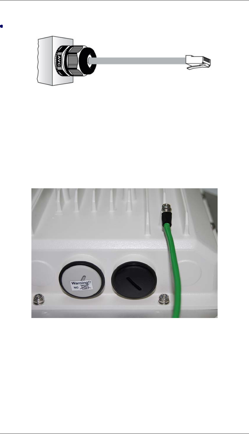
Screw the sealing on the gland and tighten.
Connect Up – Step 4
Grounding
The DAP-3760 / DAP-3860 is shipped with a grounding wire. The unit must be properly
grounded to protect against power surges. The DAP-3760 / DAP-3860 grounding point can be
found on the bottom of the unit. It is supplied with an appropriate grounding lug for attachment
to the ODU. Ground the Wire.
Grounding
Power on
To power up the DAP-3760 / DAP-3860, follow the steps bellow:
1. Plug a user-supplied Cat-5 Ethernet cable from your wired LAN (or a computer) into the
power injector RJ-45 jack (DATA IN);
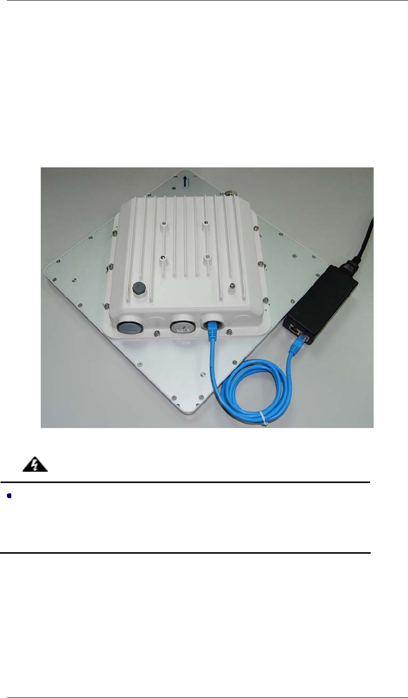
Chapter 3 Hardware Installation Page 20
2. Plug a user-supplied Cat-5 Ethernet cable from the DAP-3760 / DAP-3860 into the
power injector RJ-45 jack (P+DATA OUT);
3. Connect the power module to the power injector and plug the AC cord into an AC power
receptacle;
4. After being powered on, the device will send out the beep sound lasting about 1.5
seconds, informing you that the DAP-3760 / DAP-3860 is powered up! Wait for about
60 seconds the system will be initialized and start working.
1.
Make sure PoE is correctly connected to the RJ-45 port on the DAP-3760 /
DAP-3860 labeled PoE+Data, otherwise the extender will be severely
damaged!
Warning:

Chapter 3 Hardware Installation Page 21
Align Antenna
After powering up the wireless bridge, align the integrated antenna to point in the approximate
direction of the remote bridge antenna.
If the antenna is at a significant angle, use binoculars, satellite global positioning system (GPS)
or reference objects to detect the remote bridge or antenna, and then manually adjust the
horizontal and vertical positions accordingly. To verify whether the two antennas are correctly
pointed to each other, ping the remote wireless bridge.
Positioning antenna is to align the local antenna to reach maximum signal strength. Using
“Align Antenna” to measure signal strength is convenient and appropriate for most
installations, but note that this method is only available in “Peer-to-Peer (CSMA)” mode.
To use “Align Antenna”, follow the steps bellow:
1. Login the Web-based management interface of wireless bridge;
2. Open “Peer-to-Peer Setup”, by clicking “Align Antenna”, “Antenna Alignment Tool”
window will popup. Set the target RSSI and click “Start” to begin alignment. If the RSSI is
below -70 dBm, align the antenna by panning the antenna from side to side and tilting up
and down while observing the RSSI value. By doing so, you will be able to know where is
the best position for the antenna to reach its maximum signal strength. During adjustment,
the device will send out the beep sound, assisting you with the alignment.

Chapter 3 Hardware Installation Page 22
3. After the two integrated antennas are well positioned, secure the bridge mounting
fasteners. The bridges now are ready to be configured and incorporated into your network.

Chapter 4 Configuration Page 23
Chapter 4 Configuration
The units to be installed should be configured before physical installation. During this process,
the installer can set the unit’s IP address to the one within desired address range and set each
unit up with the MAC address of its peer unit ready to establish a wireless link. It is
recommended that this procedure be carried out on the bench before physical installation.
This chapter describes how to configure your bridge for the first time. You can use the bridge’s
web-based interface to complete the initial configuration.
Connect the Bridge to a Local Computer
If you are configuring the bridge locally (without connecting its power injector to a wired LAN),
connect a PC to the power injector’s Ethernet port using a Category 5 Ethernet cable.
1. Assign a static IP address to your PC which is in the same network segment with the
wireless bridge. As the default IP address of this unit is 192.168.1.1, you may choose
from 192.168.1.2 to 192.168.1.254.
2. Test the link status between your PC and the wireless bridge. Start a command prompt
and execute a continuous ping command “ping 192.168.1.1 –t”. If ping to the wireless
bridge is successful (as shown below), open Internet browser and enter the bridge’s IP
address in the address filed and press Enter.
Chapter 4 Configuration Page 24
3. Enter the user name (admin) and password (password) to login and make configurations.
4. After configuring the bridge, remove the Ethernet cable from PC and connect the power
injector back to your wired LAN port.
Basic Settings
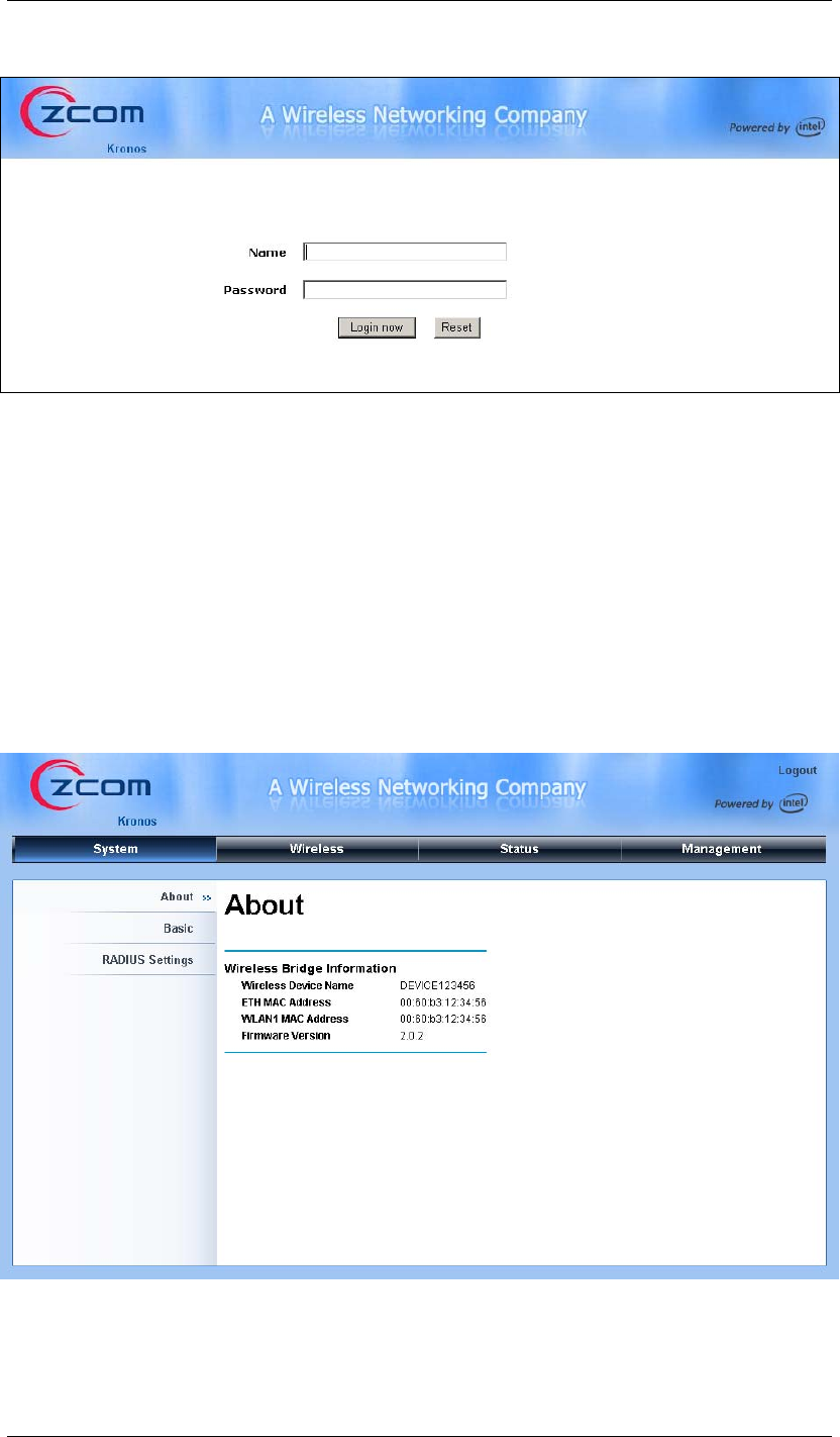
After login to the Web-based management interface, you will see the “About” page as below.
Click “Basic” in the left menu bar to make basic system configurations.
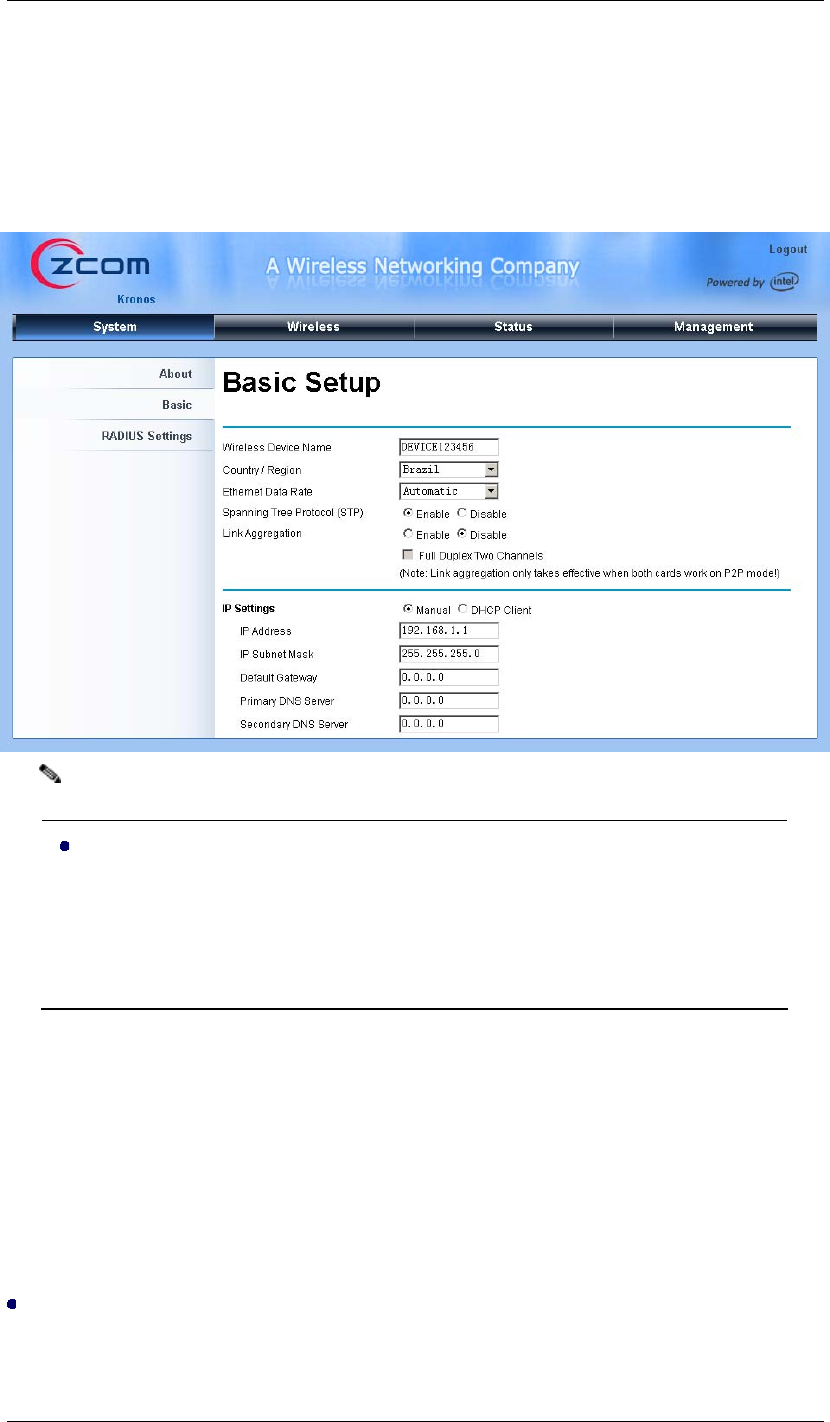
Chapter 4 Configuration Page 25
IP Address
Enter the settings obtained from your system administrator. The most important setting is IP
Address. You may manually assign an IP address or check “DHCP” to automatically obtain
one from DHCP server on your network.
Do not change the IP address of the bridge while you are configuring with
Web-based management interface, otherwise you will disassociate from it! If
this occurs, login again with that new IP address; if DHCP is enabled then,
login again by entering bridge’s wireless device name in the IP address field.
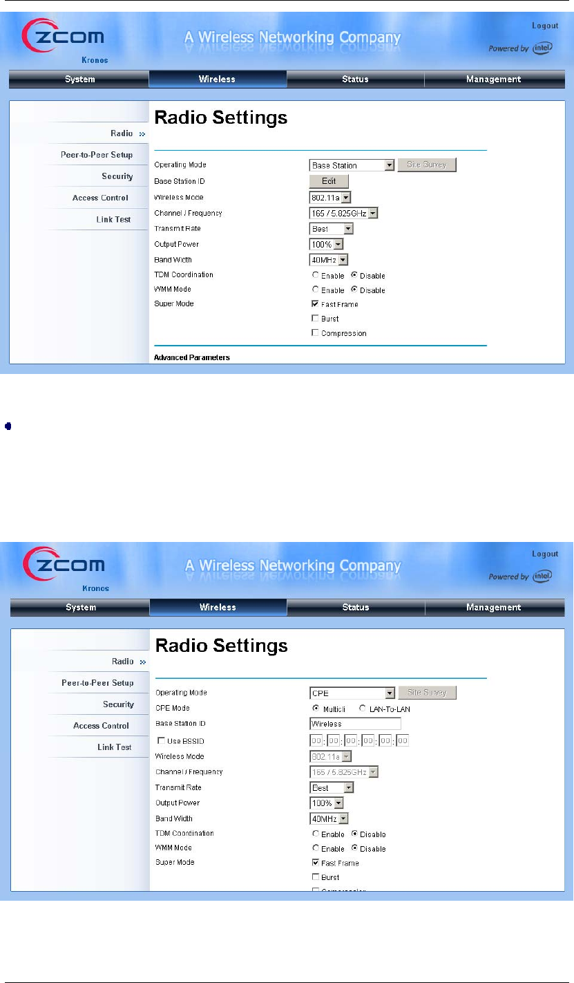
Operating Mode
Four operating modes are available in this bridge: Base Station, CPE, Peer to Peer (CSMA)
and Peer to Peer (TDMA). Open “Radio” in “Wireless” and select the mode suitable for your
application.
Base Station
Under this mode, the bridge connects directly to the main Ethernet LAN and receives
connectivity from other CPE bridges.
Note:
Chapter 4 Configuration Page 26
CPE
Under this mode, the bridge connects to a remote LAN and that Base Station. Select “Multicli”
or “LAN-to-LAN” for your network application and specify the SSID of the corresponding
Base Station.
Chapter 4 Configuration Page 27
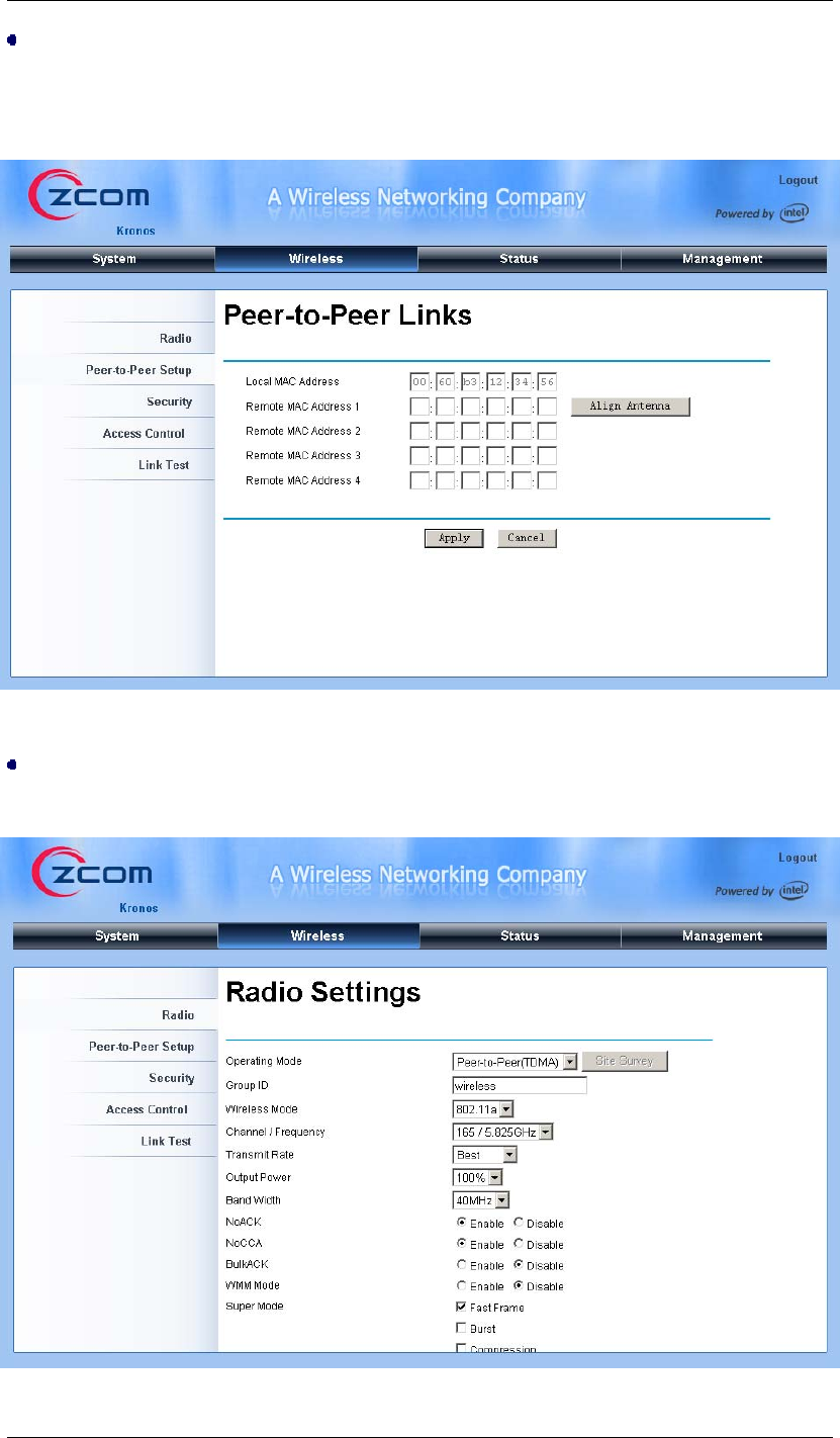
Peer to Peer (CSMA)
Under peer-to-peer (CSMA) mode, set the same channel for all the peer units. Open
“Peer-to-Peer Links” (as below) page to enter the MAC address of the remote peer unit.
Peer to Peer (TDMA)
Under peer-to-peer (TDMA) mode, set one group ID for all the peer units.

Chapter 4 Configuration Page 28
Base Station ID
The SSID is a unique identifier that bridges use to associate to each other. It is case-sensitive
and consists of no more than 32 alphanumeric characters. By default, it is set to “Wireless”.
Output Power
If the bridges are installed less than 328ft (100m) apart, the output power should be adjusted
lower to avoid overloading the bridge’s receivers.
To configure the output power, open “Radio” and select the appropriate output power value:
Full, Half, and Quarter.
Channel/Frequency
Channel varies much as the available band differs from country to country. Select a proper
operating channel in the drop-down list according to your situation.
Advanced Settings
After basic settings, you might need to configure some parameters to optimize performance or
enhance your network security.
Super Mode
The super mode is designed to enhance throughput by decreasing data waiting time slot.
Open “Radio” and check “Fast Frame”, “Burst’ or “Compression” box accordingly.
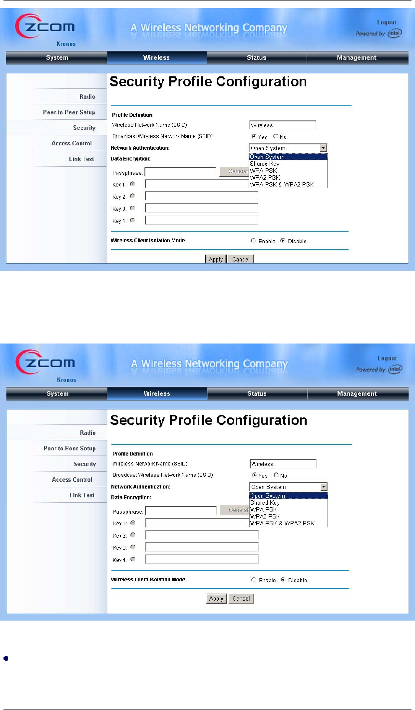
Security Settings
Security settings are effective to prevent unauthorized access to your network. It supports
open system, shared key, WPA-PSK, WPA2-PSK and WPA-PSK&WPA2-PSK. To enable
security, open “Security” page as below:
Chapter 4 Configuration Page 29
Alternatively, under “Base Station” mode, by clicking “Edit”, the “Security Profile
Configuration” window will popup. You can set the SSID and security configuration here.
Network Authentication Type
Open System: It allows any device to join the network without performing security check.

Chapter 4 Configuration Page 30
Shared Key: Encryption strength and key are required.
WPA-PSK: No need for specific authentication server. In this so-called WPA Pre-Shared
Key, all you have to do is just pre-enter a key in each WLAN node and this is the common
way to be adopted in large and middle enterprise as well as residential network.
WPA2-PSK: Only all the clients support WPA2, can it be available. If it is selected, the
data encryption type must be AES and the passphrase is required.
WPA-PSK & WPA2-PSK: It provides options of WPA (TKIP) or WPA2 (AES) encryption for
the client. If it is selected, the data encryption must be TKIP + AES and the WPA
passphrase is required.
Data Encryption
Select your desired authentication and enter the encryption keys. STA and bridge must use the
same keys. By default, it is set to “None”.
64 bit: 10 Hexadecimal digits (any combination of 0-9, a-f, or A-F)
128 bit: 26 Hexadecimal digits (any combination of 0-9, a-f, or A-F)
152 bit: 32 Hexadecimal digits (any combination of 0-9, a-f, or A-F)
TKIP: It will be automatically enabled if WPA-PSK authentication is selected.
AES: It will be automatically enabled if WPA2-PSK authentication is selected.
AES & TKIP: It allows for backwards compatibility with devices using TKIP.
Security Encryption Keys
Passphrase: Enter a passphrase and click “Generate Keys” button. You can also enter
keys manually. These keys must match the ones of other wireless stations or bridges.
Only 8 to 63 characters can be entered.
Key1~Key4: Select the key to be used as the default one and data transmissions are
always encrypted using this default key. The other keys are only used to decrypt received
data.

Chapter 5 Troubleshooting Page 31
Chapter 5 Troubleshooting
This chapter provides troubleshooting procedures for basic problems with the bridge.
Q 1. What if my bridge fails to connect to the remote one?
• Ethernet Link: Check the availability of power to the bridge by observing the LED
status on the power injector.
- Green: The wireless bridge is connecting to the backhaul network.
- Off: The wireless bridge disconnects from the wired network, check whether the
power cord and Ethernet cables to the network and bridge are correctly connected.
• Basic Configurations: Mismatched basic settings among bridges are the most
common cause of connectivity fail. If the bridge does not associate with a remote
bridge, check whether options in each device are identical.
• Security Settings: Remote bridges attempting to authenticate to your bridge must
support the same security options configured in your bridge, such as WEP and WPA
(2)-PSK. If your bridge fails to associate with others, check whether the security
settings are the same as your bridge settings.
• Antenna Alignment: If the methods above are all checked to be correct, you can
observe and verify antenna alignment with RSSI value.
Q 2. What if I forget my password?
You may restore the bridge to its factory default settings in “Backup/Restore Settings” from
“Management”.
Q 3. What if my bridge encounters a firmware failure?
Retrieve the settings you have backed up previously in “Backup/Restore Settings” from
“Management”.

Chapter 6 Technical Support Page 32
Chapter 6 Technical Support
If you still have any trouble using the wireless bridge or you would like to require additional
support, please check the following information for support:
Z-Com, Inc.
Taiwan
Business
Center
7F-2, No.9. Prosperity
RD. I Science-Based
Industrial Park
Hsinchu ,300 Taiwan
Tel: +886-3-5777364
Fax:+886-3-5773359
Sales Contact
info@zcom.com.tw
FAE Support
support@zcom.com.tw
Zcomax Technologies, Inc.
California
Business
Center
14545 Valley View Ave.,
Suite "S"
Santa Fe Springs, CA
90670
Tel: +1-562-926-4588
Fax:+1-562-926-7885
New
Jersey
Business
Center
98 Ford Road, Suite 3-F,
Denville, NJ 07834, USA
Tel: +1-973-664-0310
Fax:+1-973-664-0313
Sales/Product Inquiries:
sales@zcomax.com
Tech Support/Questions:
support@zcomax.com
ZCOMAX - United Kingdom Limited
European
Business
Centre
19 Colindale Avenue
London NW9 5DS UK
Tel:+44-(0)-20-8982-8200
Fax:+44-(0)-20-8201-3232
Sales Contact
sales@zcomax.co.uk
FAE Support
support@zcomax.co.uk
Z-Dotcom, Inc
China
Business
Centre
168 Long Pan Zhong
Road, Jiangsu Software
Park, Suite 118 Nanjing,
China 210002
Tel: +86-25-84661300
Fax:+86-25-84661313
Sales Contact
sales@zcom.com.cn
FAE Support
support@zcom.com.cn