D Link DCS5222L DCS-5222L HD Wireless N Pan/Tile Network Camera User Manual
D Link Corporation DCS-5222L HD Wireless N Pan/Tile Network Camera
D Link >
User Manual
DCS-5211L HD Power over
Ethernet Pan/Tile Network
Camera
DCS-5222L HD Wireless N
Pan/Tile Network Camera

iD-Link DCS-5222L/DCS-5211L User Manual
Manual Overview
This manual contains the following sections:
Section 1 - “Product Overview” describes what is included with the DCS-5222L/DCS-5211L camera, and things to consider
before installing.
Section 2 - “mydlink Portal” provides detailed information on usage and configuration of your product with
www.mydlink.com.
Section 3 - “Installation” describes how to install the camera on your network .
Section 4 - “Conguration” describes how to congure the settings on your DCS-5222L/DCS-5211L camera.
Section 5 - “Troubleshooting” explains how to resolve common issues.
Section 6 - “Appendix” contains special procedures and technical specications.

iiD-Link DCS-5222L/DCS-5211L User Manual
D-Link reserves the right to revise this publication and to make changes in the content hereof without obligation to
notify any person or organization of such revisions or changes. Information in this document may become obsolete
as our services and websites develop and change. Please refer to the www.mydlink.com website for the most current
information.
Manual Revisions
Trademarks
D-Link and the D-Link logo are trademarks or registered trademarks of D-Link Corporation or its subsidiaries in the
United States or other countries. All other company or product names mentioned herein are trademarks or registered
trademarks of their respective companies.
Copyright © 2010 by D-Link Corporation.
All rights reserved. This publication may not be reproduced, in whole or in part, without prior expressed written permission
from D-Link Corporation.
Revision Date Description
1.0 November 28, 2011 • DCS-5222L/DCS-5211L Version 1 with rmware version 1.00_0922

iiiD-Link DCS-5222L/DCS-5211L User Manual
Federal Communication Commission Interference
Statement
This device complies with Part 15 of the FCC Rules. Operation is subject to the following two conditions: (1) This device may
not cause harmful interference, and (2) this device must accept any interference received, including interference that may
cause undesired operation.
This equipment has been tested and found to comply with the limits for a Class B digital device, pursuant to Part 15 of
the FCC Rules. These limits are designed to provide reasonable protection against harmful interference in a residential
installation. This equipment generates, uses and can radiate radio frequency energy and, if not installed and used in
accordance with the instructions, may cause harmful interference to radio communications. However, there is no guarantee
that interference will not occur in a particular installation. If this equipment does cause harmful interference to radio or
television reception, which can be determined by turning the equipment o and on, the user is encouraged to try to correct
the interference by one of the following measures:
- Reorient or relocate the receiving antenna.
- Increase the separation between the equipment and receiver.
- Connect the equipment into an outlet on a circuit dierent from that to which the receiver is connected.
- Consult the dealer or an experienced radio/TV technician for help.
FCC Caution: Any changes or modications not expressly approved by the party responsible for compliance could void the
user’s authority to operate this equipment.
This transmitter must not be co-located or operating in conjunction with any other antenna or transmitter.

ivD-Link DCS-5222L/DCS-5211L User Manual
Radiation Exposure Statement:
This equipment complies with FCC radiation exposure limits set forth for an uncontrolled environment. This equipment
should be installed and operated with minimum distance 20cm between the radiator & your body.
FOR COUNTRY CODE SELECTION USAGE (WLAN DEVICES)
Note: The country code selection is for non-US model only and is not available to all US model. Per FCC regulation, all WiFi
product marketed in US must xed to US operation channels only.
Industry Canada statement:
This device complies with RSS-210 of the Industry Canada Rules. Operation is subject to the following two conditions:
(1) This device may not cause harmful interference, and (2) this device must accept any interference received, including
interference that may cause undesired operation.
Ce dispositif est conforme à la norme CNR-210 d’Industrie Canada applicable aux appareils radio exempts de licence. Son
fonctionnement est sujet aux deux conditions suivantes: (1) le dispositif ne doit pas produire de brouillage préjudiciable,
et (2) ce dispositif doit accepter tout brouillage reçu, y compris un brouillage susceptible de provoquer un fonctionnement
indésirable.
Radiation Exposure Statement:
This equipment complies with IC radiation exposure limits set forth for an uncontrolled environment. This equipment
should be installed and operated with minimum distance 20cm between the radiator & your body.
Déclaration d’exposition aux radiations:
Cet équipement est conforme aux limites d’exposition aux rayonnements IC établies pour un environnement non contrôlé.
Cet équipement doit être installé et utilisé avec un minimum de 20 cm de distance entre la source de rayonnement et votre
corps.

vD-Link DCS-5222L/DCS-5211L User Manual
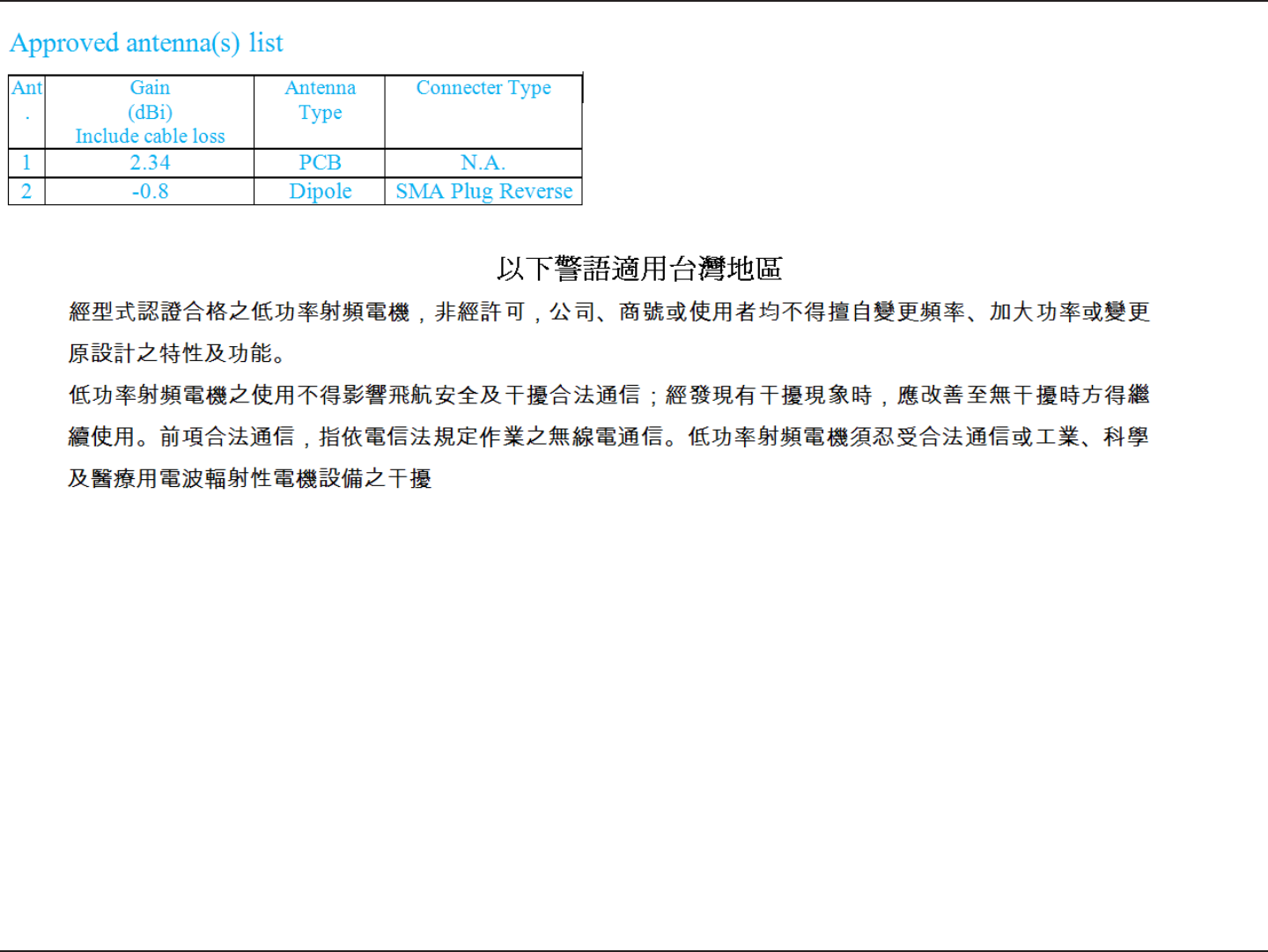
This device has been designed to operate with an antenna having a maximum gain of [2.34] dBi. Antenna having a higher
gain is strictly prohibited per regulations of Industry Canada. The required antenna impedance is 50 ohms.
Under Industry Canada regulations, this radio transmitter may only operate using an antenna of a type and maximum (or
lesser) gain approved for the transmitter by Industry Canada. To reduce potential radio interference to other users, the
antenna type and its gain should be so chosen that the equivalent isotropically radiated power (e.i.r.p.) is not more than that
necessary for successful communication.
This radio transmitter (IC: 4216A-DCS5222L / Model: DCS-5222L) has been approved by Industry Canada to operate with the
antenna types listed below with the maximum permissible gain and required antenna impedance for each antenna type
indicated. Antenna types not included in this list, having a gain greater than the maximum gain indicated for that type, are
strictly prohibited for use with this device.
Ce dispositif a été conçu pour fonctionner avec une antenne ayant un gain maximal de dBi [2.34]. Une antenne à gain plus
élevé est strictement interdite par les règlements d’Industrie Canada. L’impédance d’antenne requise est de 50 ohms.
Conformément à la réglementation d’Industrie Canada, le présent émetteur radio peutfonctionner avec une antenne d’un
type et d’un gain maximal (ou inférieur) approuvé pourl’émetteur par Industrie Canada.
Dans le but de réduire les risques de brouillage radioélectriqueà l’intention des autres utilisateurs, il faut choisir le type
d’antenne et son gain de sorte que lapuissance isotrope rayonnée équivalente (p.i.r.e.) ne dépasse pas l’intensité nécessaire
àl’établissement d’une communication satisfaisante.
Le présent émetteur radio (IC: 4216A-DCS5222L / Model: DCS-5222L) a été approuvé par Industrie Canada pour fonctionner
avec les types d’antenne énumérés ci-dessous et ayant un gain admissible maximal et l’impédance requise pour chaque
type d’antenne. Les types d’antenne non inclus dans cette liste, ou dont le gain est supérieur au gain maximal indiqué, sont
strictement interdits pour l’exploitation de l’émetteur.
viD-Link DCS-5222L/DCS-5211L User Manual

viiD-Link DCS-5222L/DCS-5211L User Manual
Table of Contents
Manual Overview .......................................................................................................................... i
Manual Revisions ................................................................................................................ii
Trademarks ........................................................................................................................ii
Product Overview ........................................................................................................................ 1
Features ............................................................................................................................ 2
Package Contents ............................................................................................................... 3
System Requirements ......................................................................................................... 4
Hardware Overview DCS-5222L ......................................................................................... 5
Front ....................................................................................................................... 5
Back ........................................................................................................................ 6
Hardware Overview DCS-5211L ......................................................................................... 7
Front ....................................................................................................................... 7
Back ........................................................................................................................ 8
Mydlink Portal ........................................................................................................................... 10
Camera Status ................................................................................................................. 11
Live Video ........................................................................................................................ 12
Camera Settings ............................................................................................................... 13
Camera Info ..................................................................................................................... 14
Installation ................................................................................................................................. 15
Starting the Camera Setup Wizard ..................................................................................... 15
Hardware Installation ....................................................................................................... 16
Inserting a Micro SD Card....................................................................................... 16
Connect the Ethernet Cable ...................................................................................... 17
Connect the Power Adapter ..................................................................................... 17
Using the Configuration Menu ...................................................................................................... 18
Web-based Configuration Utility .......................................................................................... 19
Live Video ........................................................................................................................ 20
Camera .................................................................................................................. 20
Setup ............................................................................................................................... 21
Wizard ................................................................................................................... 21
Network Setup ....................................................................................................... 22
Wireless ................................................................................................................ 24
Dynamic DNS.......................................................................................................... 25
Image Setup ........................................................................................................... 26
Audio and Video ...................................................................................................... 27
Motion Detection ..................................................................................................... 29
Time and Date ......................................................................................................... 30
Camera Control ...................................................................................................... 31
SD Recording ......................................................................................................... 33
Snapshot ................................................................................................................ 35
Digital Output .......................................................................................................... 36
SD Management ...................................................................................................... 37
Maintenance ........................................................................................................... 38
Admin .................................................................................................................... 38
System .................................................................................................................. 39
Firmware Upgrade ................................................................................................. 40
Status .............................................................................................................................. 41
Device Info ............................................................................................................. 41
Table of Contents

viiiD-Link DCS-5222L/DCS-5211L User Manual
Table of Contents
Log ........................................................................................................................ 42
Help................................................................................................................................. 43
Troubleshooting .......................................................................................................................... 45
Technical Specifications - Remote Control Unit .............................................................................. 46
Technical Specifications .............................................................................................................. 48

1D-Link DCS-5222L/DCS-5211L User Manual
Section 1 - Product Overview
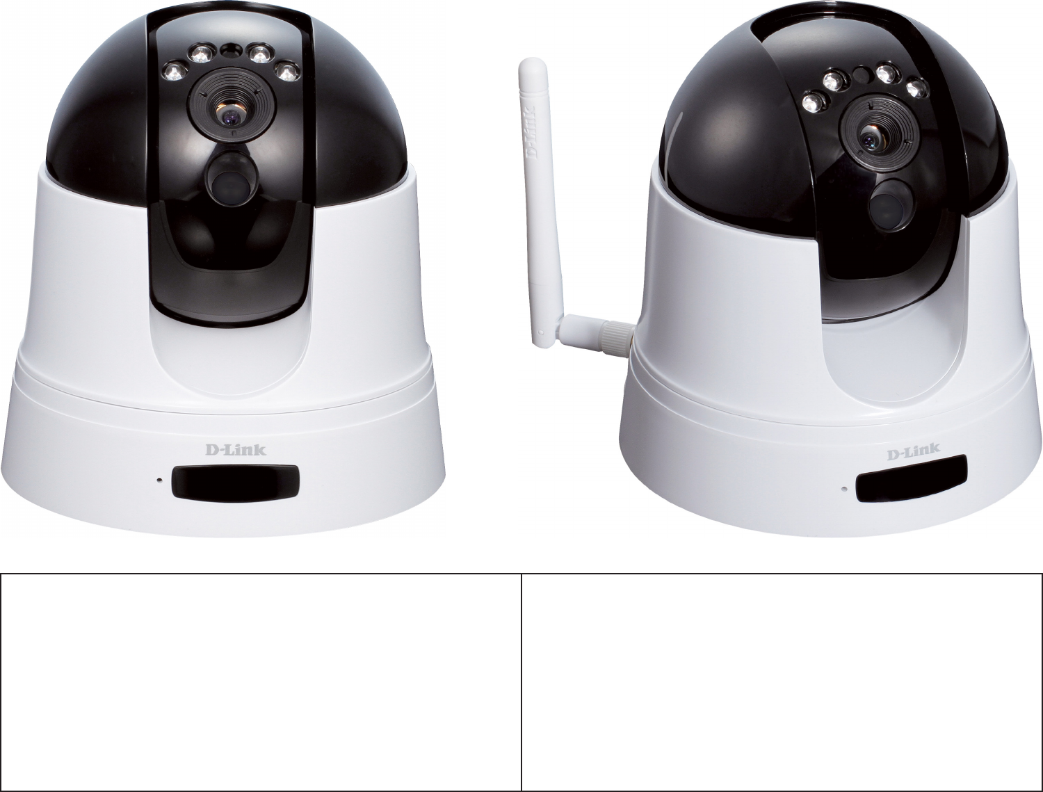
Thank you for purchasing the DCS-5222L/DCS-5211L Network Camera. The DCS-5222L/DCS-5211L is a versatile solution for your
small oce or home. The DCS-5222L/DCS-5211L is a complete system with a built-in CPU and web server that transmits high
quality video images for security and surveillance. DCS-5222L/DCS-5211L can be accessed remotely, and controlled from any
PC/Notebook over your local network or across the Internet via a web browser. The DCS-5222L/DCS-5211L is simple to install
and intuitive web-based interface oer easy integration with your Ethernet/Fast Ethernet or 802.11g/n wireless network (Only
the DCS-5222L oers wireless connectivity) . The DCS-5222L/DCS-5211L comes with remote monitoring and motion detection
features for a complete and cost-eective home security solution.
Product Overview
• Remotely monitor your home or oce over the Internet
• Web-based Recording to a PC’s local hard drive – no software required
• Mydlink-enabled technology simplies setup by automatically conguring network settings
• Motion detection to trigger recording and send e-mail alerts
• DDNS support for web access using an easy-to-remember domain name
• Administrator/User password protection
• UPnP support for easy network setup and conguration
• 1 lux CMOS sensor for low-light environments
• 3GPP mobile surveillance
• Simultaneous MJPEG and MPEG-4 streams allows optimization of both image quality and bandwidth
eciency
• 802.11g/n wireless connectivity (DCS-5222L)
• WPS support for easy wireless network setup (DCS-5222L)

2D-Link DCS-5222L/DCS-5211L User Manual
Section 1 - Product Overview
• Simple to Use: The DCS-5222L/DCS-5211L is a stand-alone system with a built-in CPU, requiring no special hardware or
software such as PC frame grabber cards. Setup is simple, with mydlink-enabled technology which helps automatically
congure your camera’s network settings, eliminating the need to set complicated settings on your router.
• Supports a Variety of Platforms: The DCS-5222L/DCS-5211L supports TCP/IP networking, HTTP, and other Internet
related protocols. It can also be integrated easily into other Internet/Intranet applications because of its standards-based
features.
• Remote Snapshot Images and Recording: Using the snapshot and recording features on the DCS-5222L/DCS-5211L,
it is possible to save snapshots and record video and audio directly from the web browser to a local hard drive, without
installing any software, making it convenient to capture any moment from a remote location.
• Record Directly to a NAS: The DCS-5222L/DCS-5211L allows you to record directly to a local network area storage device
without the use of a dedicated PC for storing recorded video.
• Low Light Recording: The DCS-5222L’s infrared light illumination allows the capture of video in rooms with minimal
lighting, making it ideal for use in low-light environments.
• Web Conguration: Using a standard Web browser, administrators can congure and manage the Network Camera directly
from its own Web page via Intranet or Internet.
• Broad Range of Applications: With today’s high-speed Internet services, the DCS-5222L/DCS-5211L Network Cameras
can provide an ideal solution for live video over the Intranet and for remote monitoring. The DCS-5222L/DCS-5211L allow
remote access from a Web browser for live image viewing and management of the network cameras anytime, from anywhere
in the world. The network cameras have a wide range of applications, including industrial and public monitoring of homes,
oces, banks, hospitals, child-care centers, and amusement parks.
• 802.11n Wireless Connectivity: The DCS-5222L oers both 802.11n wireless and Ethernet/Fast Ethernet connectivity,
making the DCS-5222L easy to integrate into your existing network environment. The DCS-5222L/DCS-5211L works with a
Ethernet based network for traditional wired environments. The DCS-5222L also works with 802.11g/n/b routers or access
points for added exibility.
Features
3D-Link DCS-5222L/DCS-5211L User Manual
Section 1 - Product Overview
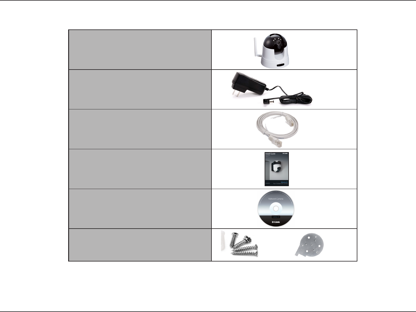
DCS-5222L or DCS-5211L Network
Camera; and a Remote Control Unit
Power Adapter
CAT5 Ethernet Cable
Quick Installation Guide
CD-ROM
Screw, wall and ceiling mount kit
Package Contents
Note: Using a power supply with a different voltage rating than the one included with the DCS-5222L/DCS-5221L will cause damage and
void the warranty for this product.
If any of the above items are missing from your package, please contact your retailer.

4D-Link DCS-5222L/DCS-5211L User Manual
Section 1 - Product Overview
System Requirements
Network Requirements • Wired (10/100/1000 Fast Ethernet) network
• Wireless 802.11g/n/b network (DCS-5222L only)
CD Setup Wizard
Requirements
• An Internet connection
• A router connected to your broadband modem
Computer with the following:
• A PC with a wired connection to your router
• Windows® 7, Vista® (32/64-bit), or XP installed
• Internet Explorer 6 or higher with ActiveX controls
enabled
Web-based Conguration
Utility Requirements
Computer with the following:
• Windows® based operating system
• An installed Ethernet adapter
Browser Requirements:
• Internet Explorer 7.0 or higher
• Firefox 3.0 or higher
• Safari 3.0 or higher
Windows® Users: Make sure you have the latest version
of Java installed. Visit www.java.com to download the
latest version.
myDlink Website
Requirements
• Subscription with an Internet Service Provide (ISP)
with 256 Kbps minimum for remote video viewing
• Computer with: Microsoft Internet Explorer 6 or higher
with ActiveX Support
5D-Link DCS-5222L/DCS-5211L User Manual
Section 1 - Product Overview
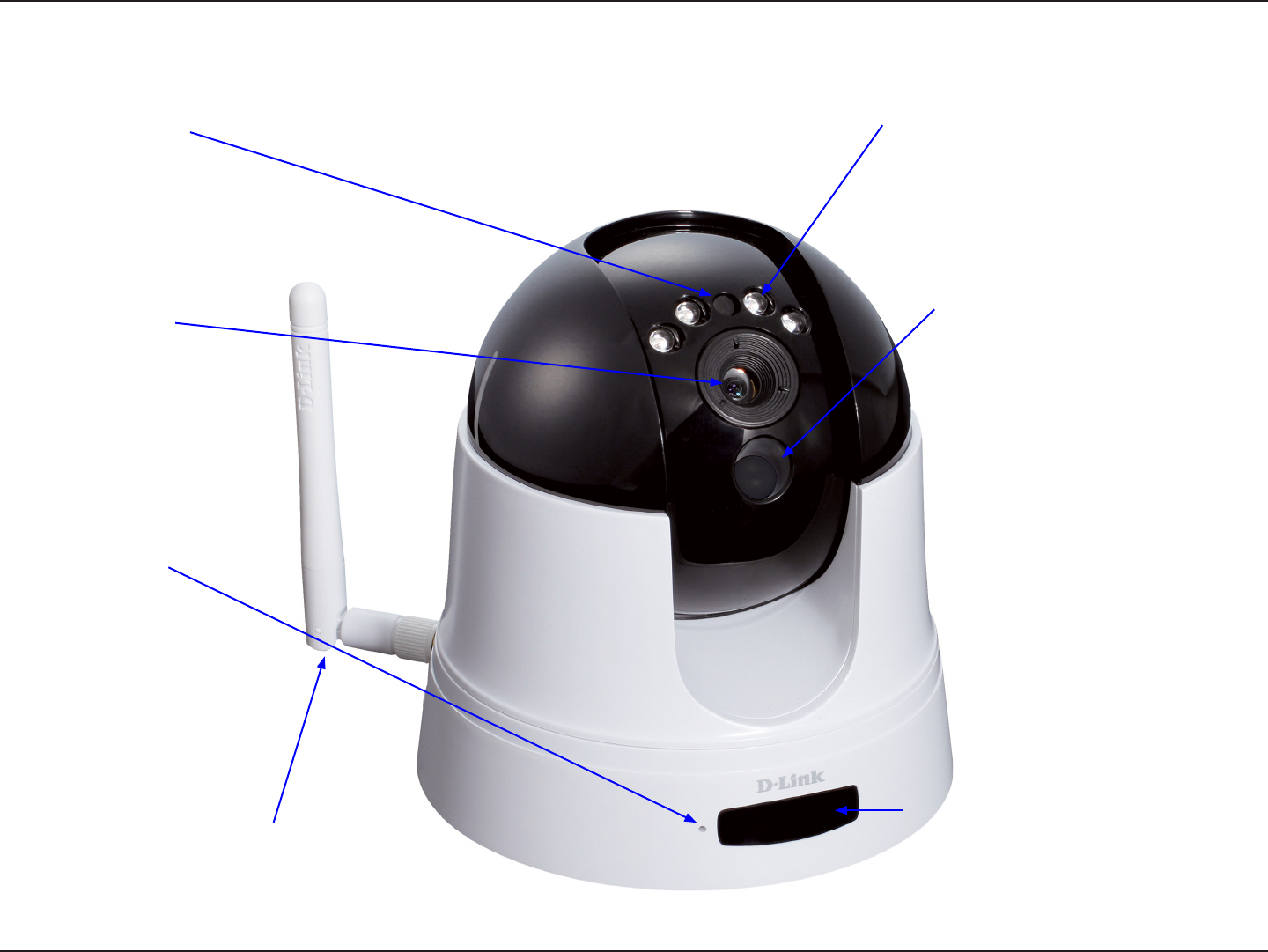
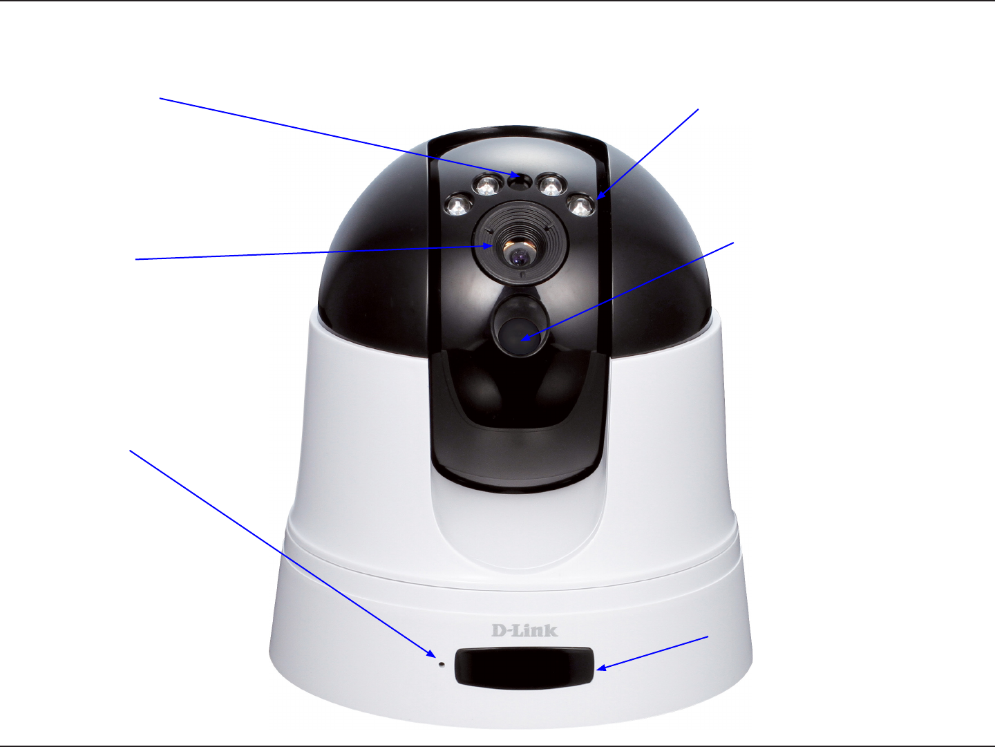
Day/Night Vision LED’s
Light Sensor
Hardware Overview DCS-5222L
Front
Remote Control Receiver
Wireless Antenna
PIR Motion Sensor
Microphone
Camera Lens
6D-Link DCS-5222L/DCS-5211L User Manual
Section 1 - Product Overview
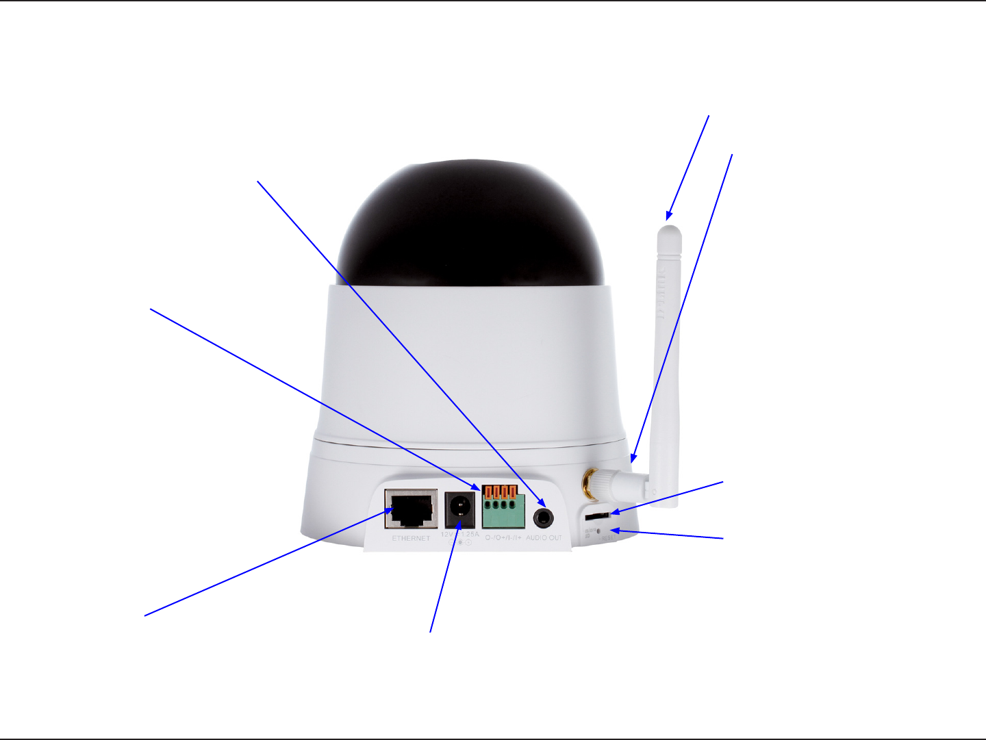
Hardware Overview DCS-5222L
Back
Power jack
Connects to the power adapter.
Ethernet port
Connects to a PC or network through
an Ethernet connection.
Wireless Antenna
WPS Button
I/O Connector
Connect an I/O cable to the DCS-
5222L.
Audio Out
Connect headphones/speakers to
provide audio out .
Micro SD
Insert Micro SD card here.
Reset Button
Press and hold to reset to factory
standard.
7D-Link DCS-5222L/DCS-5211L User Manual
Section 1 - Product Overview
Light Sensor
Day/Night Vision LED’s
Hardware Overview DCS-5211L
Front
Remote Control Receiver
PIR Motion Sensor
Microphone
Camera Lens
8D-Link DCS-5222L/DCS-5211L User Manual
Section 1 - Product Overview
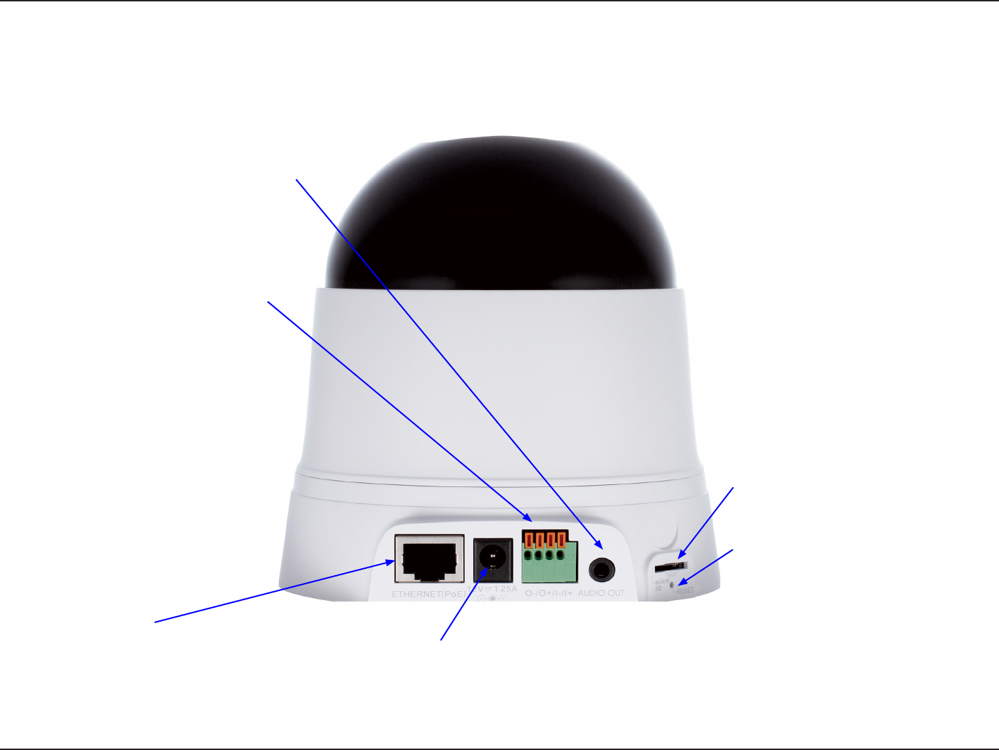
Hardware Overview DCS-5211L
Back
Power jack
Connects to the power adapter.
Ethernet port
Connects to a PC or network through
an Ethernet connection.
I/O Connector
Connect an I/O cable to the DCS-
5211L.
Audio Out
Connect headphones/speakers to
provide audio out .
Micro SD
Insert Micro SD card here.
Reset Button
Press and hold to reset to factory
standard.

9D-Link DCS-5222L/DCS-5211L User Manual
Section 1 - Product Overview
Wireless Installation Considerations
The DCS-5222L Network Camera can be connected to your network wirelessly from anywhere within its operating range. However, keep in mind
that there are factors that aect the signal strength and range of your connection. The number of objects the signal must pass through, together
with the number of radio frequencies in the area, will have an eect on the range of your signal. Remember these tips to maximize the wireless
range of your network:
• Keep the number of obstacles, such as walls or ceilings, that the signal must pass through to a minimum. Each wall or ceiling
that the signal must pass through will have an adverse eect on the range of your network.
• Please be aware of the direct and non direct lines between devices. A wall that is at an angle will have a greater surface area for the signal
to pass through than a wall not at an angle to the devices.
• Building materials can make a dierence. Try to position access points, routers and computers in such a way that the signal passes through
open doors or drywalls. Materials such as glass, metal, steel, walls (with insulation ), water (such as sh tanks), brick and concrete will
degrade your wireless signal.
• Keep the network camera at least 3 - 6 feet (1-2 meters) away from other devices which generate radio frequencies.
• If you are using a 2.4GHz cordless phone or other radio frequency source such as a microwave oven close to your wireless devices, your
wireless signal may degrade or fail. It is advisable to keep the base station of your cordless phone as far away as possible from the camera,
the base station may transmit a signal even if the phone is not in use.
10D-Link DCS-5222L/DCS-5211L User Manual
Section 2 - mydlink Portal
mydlink Portal
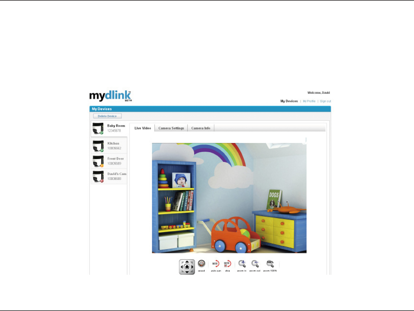
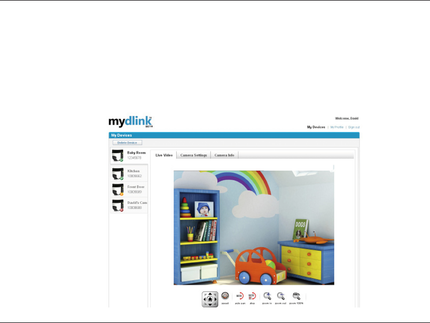
After registering your DCS-5222L camera with a mydlink account in the Camera Setup Wizard. You will be able to remotely
access your camera from the www.mydlink.com website. After signing in to your mydlink account, you will see a screen similar
to the following:

11D-Link DCS-5222L/DCS-5211L User Manual
Section 2 - mydlink Portal
Camera Status
A green tick mark indicates that your camera is online and ready to use.
A yellow exclamation point indicates that your camera is online, but the camera password
has changed. You will need to enter your new camera password to access your camera
again.
A red x indicates that your camera is oine and currently cannot be accessed remotely.
If your camera is oine, try the following:
• Check to make sure that the Internet connection to your camera is working properly.
• Try restarting your Internet router.
• Check your camera’s cable connections and make sure they are secure.
• Check to make sure that the power LED on your camera is lit solid red.
If you still cannot access your camera, reset your camera and run the Camera Setup Wizard again from the CD-
ROM included in your package.
Here, you can see the online status of each of your cameras. Your online status may be one of the following:
12D-Link DCS-5222L/DCS-5211L User Manual
Section 2 - mydlink Portal
Live Video
In the main part of the screen, the Live Video tab will be selected by default. If the camera is available, a Live Video
feed will be displayed. Video will be shown at VGA resolution (640x480) if viewing your camera from a PC on the same
local network, or at QVGA resolution (320x240) if viewing your camera from a PC on a remote network.
Note: If your router does not support UPnP, there will be a 60 second time limit when viewing your camera remotely.
Maximum only allow 3 views for video feed at a time.
13D-Link DCS-5222L/DCS-5211L User Manual
Section 2 - mydlink Portal
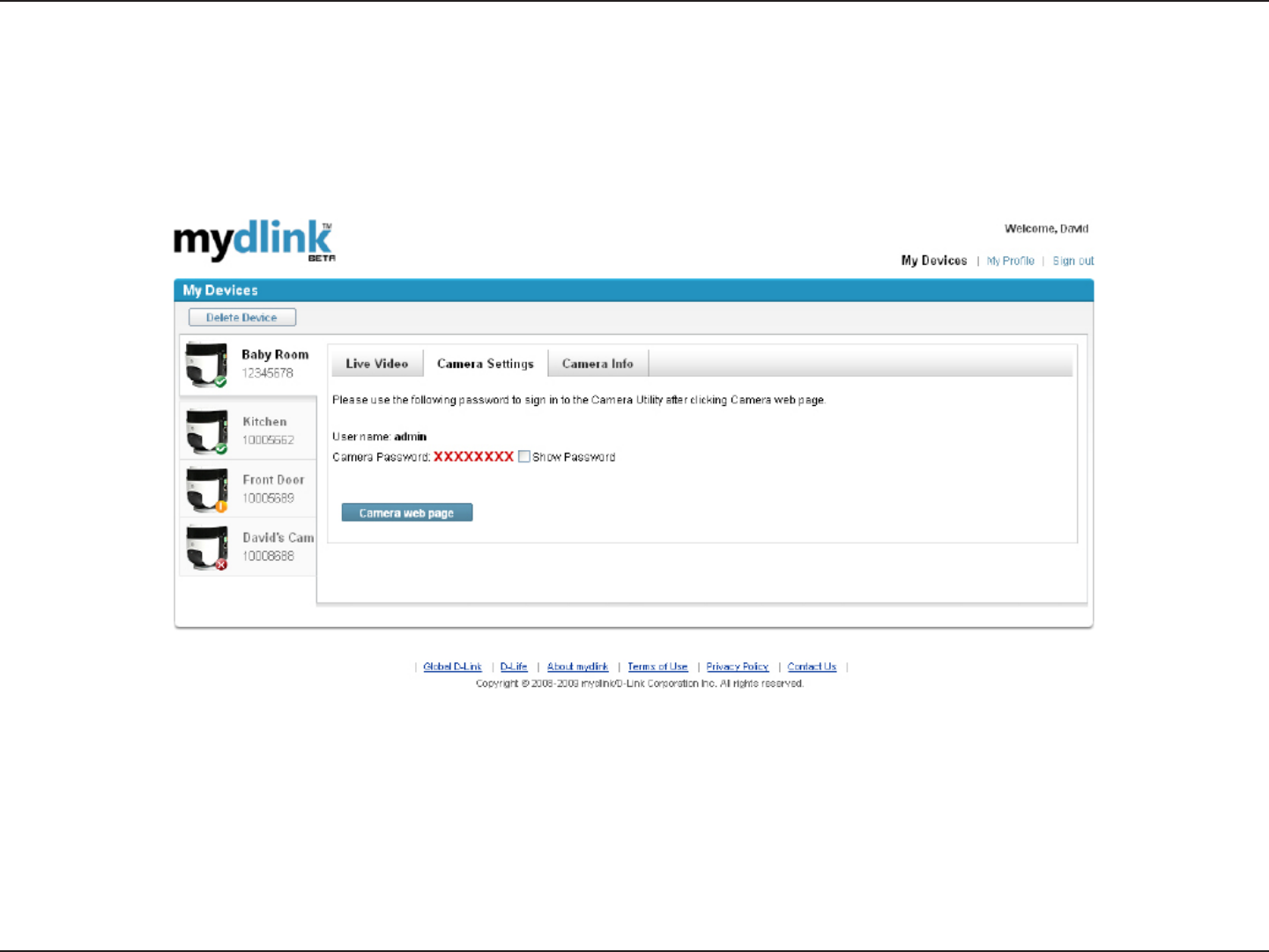
Camera Settings
The Camera Settings tab allows you to access your camera’s conguration interface. To open your camera’s conguration
interface, click Camera web page and enter the password exactly as listed on the Camera Settings page.
14D-Link DCS-5222L/DCS-5211L User Manual
Section 2 - mydlink Portal
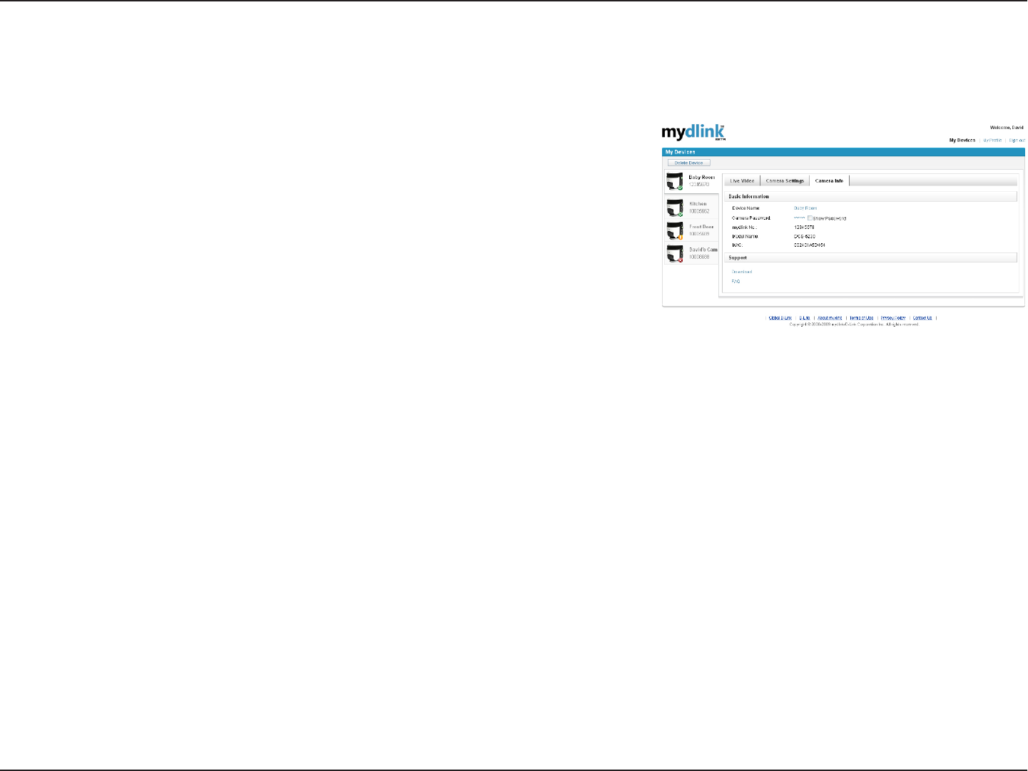
The Camera Info tab shows you various information about your camera.
Device Name: The Device Name is a unique name that you can give to your device to
help you identify it. Clicking on the Device Name will open a window for you to log in
to your camera’s conguration interface. This will then open the Maintenance > Admin
page where you can change your Device Name.
Camera Password: This shows you the current password for your camera’s conguration
interface. Clicking on the Show Password checkbox will either show or hide the
password. Clicking on the Password will open a window for you to log in to your camera’s
conguration interface. This will then open the Maintenance > Admin page where you
can change your Password.
mydlink No.: This shows you the mydlink number of your device.
Model Name: This shows you the model name of your device.
MAC Address: This shows you the MAC address of your device.
Support: This section provides you with links to various support websites and downloads related to your product.
Camera Info
15D-Link DCS-5222L/DCS-5211L User Manual
Section 3 - Installation
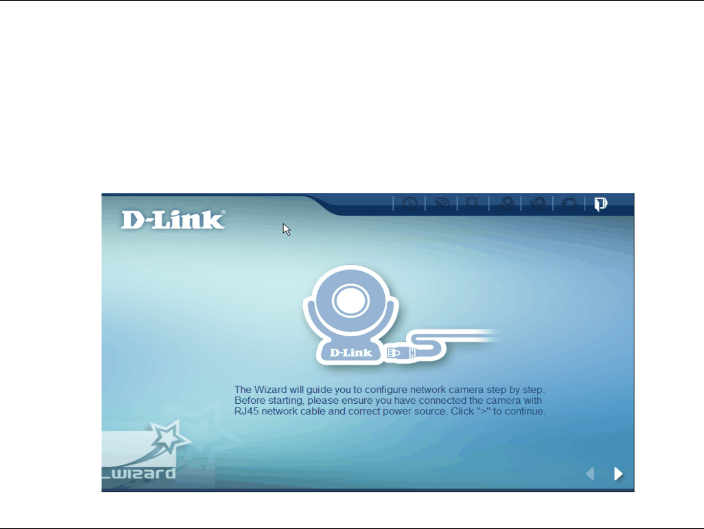
Insert the Installation CD-ROM into your computer’s CD-ROM drive to start the autorun program.
The CD-ROM will open the Camera Setup Wizard. Simply click Start to go through the Setup Wizard, which will help
you through the entire installation process from connecting your hardware to conguring your camera.
Starting the Camera Setup Wizard
Installation
16D-Link DCS-5222L/DCS-5211L User Manual
Section 3 - Installation
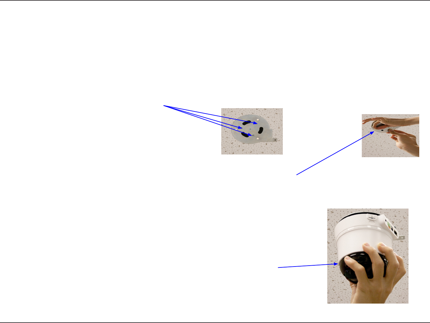
Hardware Installation
Wall and Ceiling Installation
C) Holding the IP camera rmly, place the IP camera
in the mount and swivel until secured.
B) Using the provided screws; screw the mount to the wall or ceiling, with the correct
tools, where the device is to be placed.
The device can be mounted on a wall or a partition. To install,
A) select the position that you want the camera
to sit on the ceiling or oor. The plate should
have the three ball catches facing downwards.

17D-Link DCS-5222L/DCS-5211L User Manual
Section 3 - Installation
Inserting a Micro SD Card
Insert your Micro SD card into the
Micro SD card slot on the DCS-5222L/DCS-5211L.
18D-Link DCS-5222L/DCS-5211L User Manual
Section 3 - Installation
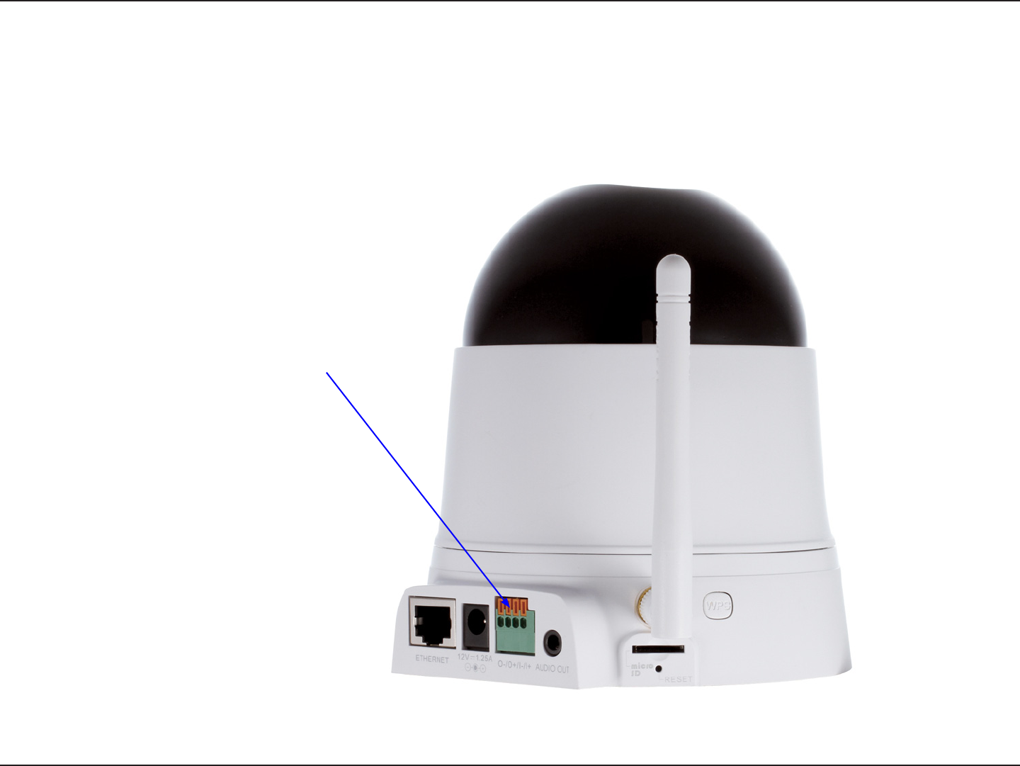
Attaching a cable to the I/O Terminal.
The 4-pin I/O connector is located at the rear
panel and provides an interface for photo-
coupled switch output and photo-coupled
input. An example of what can be done
with a digital input and digital output is the
connecting of a motion sensor to the port,
signalling the camera to take a snapshot and
trigger an alarm connected to the port.*
(*Further details and a technical specication
can be found on page 51)
19D-Link DCS-5222L/DCS-5211L User Manual
Section 3 - Installation
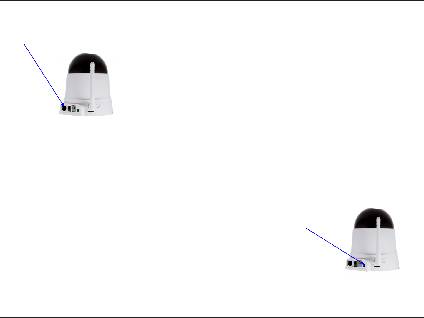
Connect the Ethernet Cable
Connecting to a router
Connect one end of the blue Ethernet cables included in your package to the Ethernet port on the back of the DCS-5222L/DCS-
5211L camera. Connect the other end of the cable to an available LAN port on your router or broadband modem.
Attach the power adapter to the power jack located on the back of the DCS-5222L/DCS-5211L
and connect the power adapter to a power outlet. After connecting the power adapter, you
should see the status LED on the front of the camera become red.
The status LED will light red when it receives power, will light green after the camera
connects to the network, and will ash green when the camera is being accessed.
Connect the Power Adapter
20D-Link DCS-5222L/DCS-5211L User Manual
Section 3 - Installation
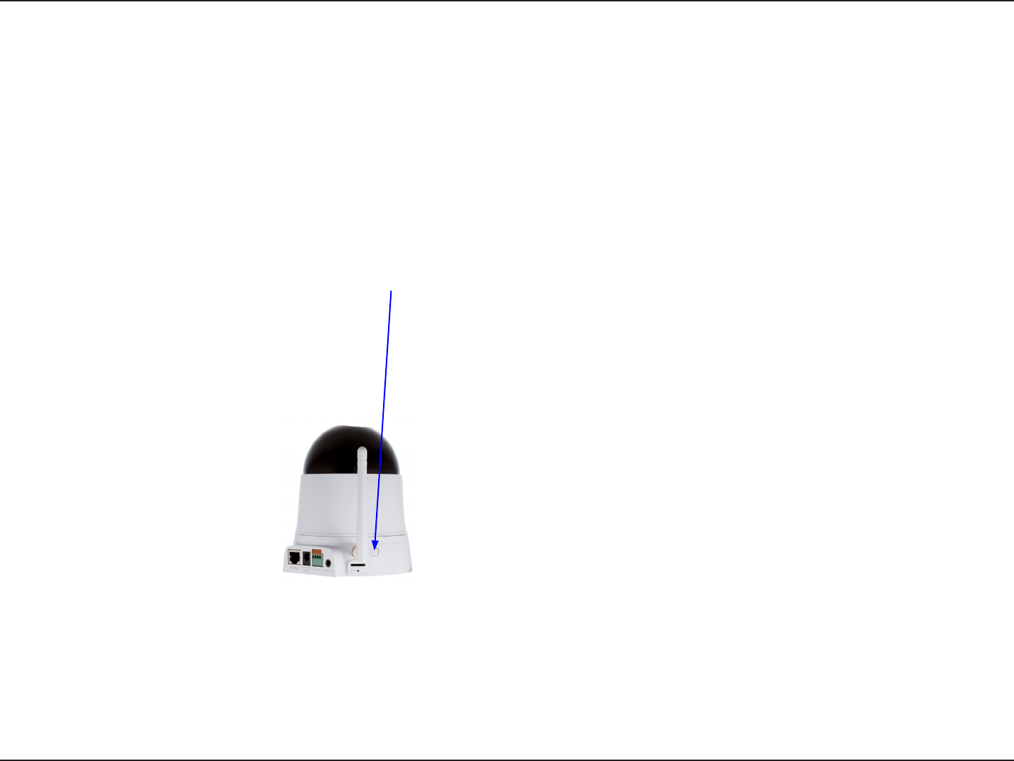
Setting up a Wireless Connection with WPS
Conguration via WPS
If your wireless access point or router supports push-button wireless protected setup (WPS), it is possible to quickly congure the
wireless network and DCS-5222L camera without using the camera’s web interface.
After plugging the power adapter to your camera and the front status LED lights up, hold down the WPS button next to the Micro
SD card slot for 3 seconds.
Now press the WPS button on your router or access point within 1 minute to activate WPS and allow your devices to automatically
congure a wireless connections.
Note: On some network routers/access points, WPS may need to be activated via the device setup or web-interface. Consult your
product’s user manual for further assistance.
21D-Link DCS-5222L/DCS-5211L User Manual
Section 4 - Configuration
Using the Configuration Menu
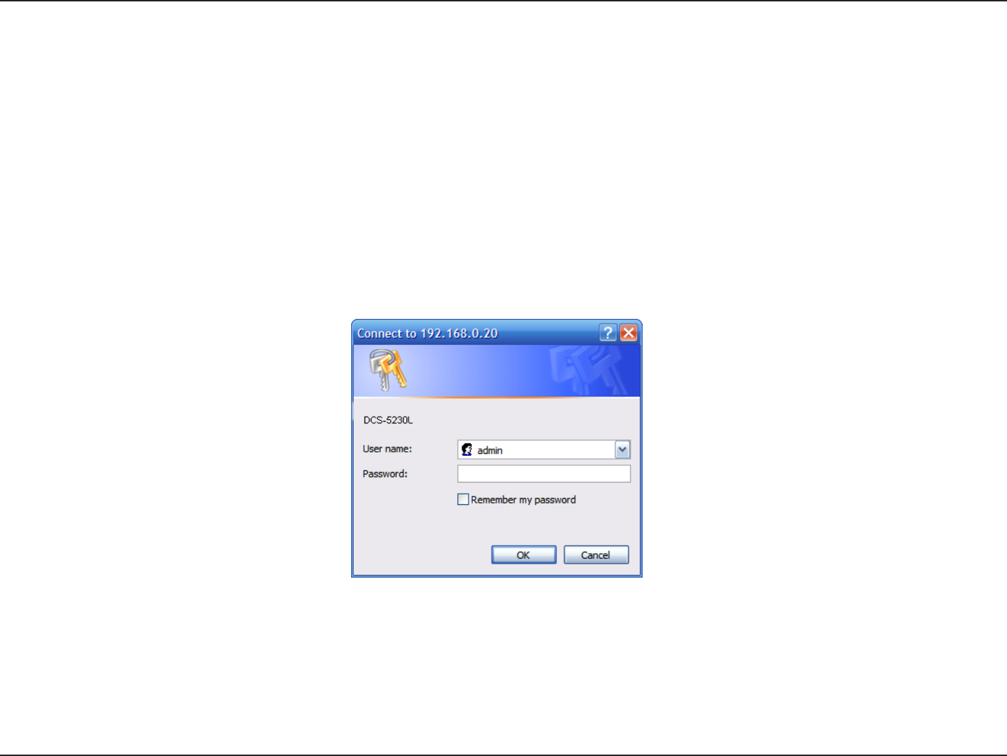
After completing the Camera Setup Wizard, you are ready to use your camera. The camera’s built-in Web conguration utility
is designed to allow you to easily access and congure your DCS-5222L/DCS-5211L. At the end of the wizard, click Go To
Camera, or enter the IP address of your camera into a web browser, such as Internet Explorer®. To log in, use the User name
admin and the password you created in the Setup Wizard. If you did not create a password, the default password is blank.
After entering your password, click OK.
Note: If you are directly connecting your PC to the camera, or if you or using the camera on a closed network, the
default IP is 192.168.0.20.
22D-Link DCS-5222L/DCS-5211L User Manual
Section 4 - Configuration
Web-based Configuration Utility
Use the following sections to set up and congure your network camera:
• LIVE VIDEO
• SETUP
• MAINTENANCE
• STATUS
• HELP
23D-Link DCS-5222L/DCS-5211L User Manual
Section 4 - Configuration
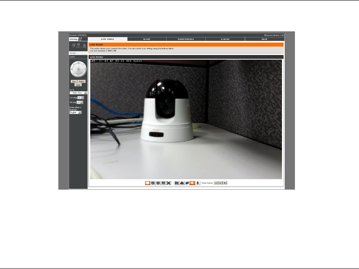
Live Video
Camera
This section shows your camera’s live video and event indicators. You may select the available thumbnails for your options of
predefined Video Profile, Full Screen mode, and action items of taking Snapshot, Recording, Set Storage Folder, Listen, Talk,
Digital Output, and IR LED. You may also select your language setting using the drop-down menu.
You can remotely rotate, pan and tilt the camera pointing direction. In addition, you can also zoom in and out of the live video
image using the controller. The pan/tilt speed can be adjusted on this page, and the “Go To” position can be congured at the
Setup > Preset Position page.
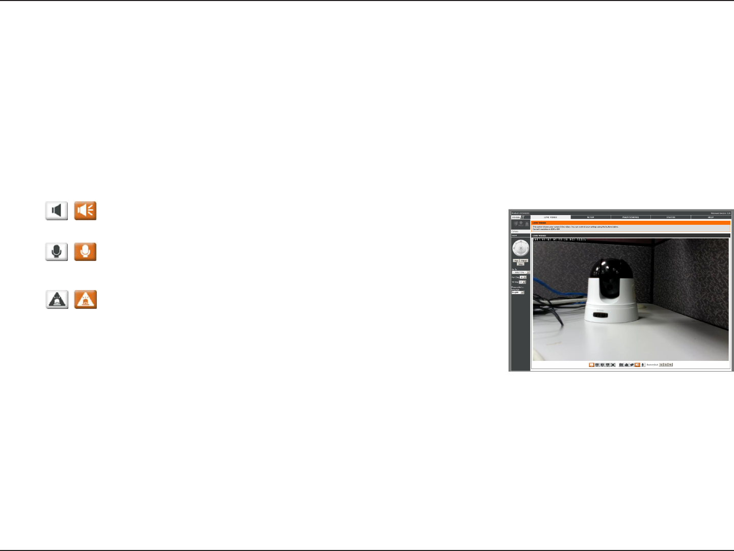
Start/Stop Audio:
Start/Stop Talking:
Start/Stop Digital Output:
This button toggles the built-in microphone on and o, allowing you to hear
audio from the area surrounding your camera. Audio is on by default.
This will toggle audio to a speaker (not included) connected to the camera's
Audio Out port. This can be used to communicate with others near the
camera.
This button will toggle the digital output on or o.
Use the Pan / Tilt / Zoom Action Pad to control the camera’s pan or tilt. The large tree
icon controls the zoom in function. The small tree icon on the right side controls the
zoom out function. The Home button can move the camera to the preset home position.
Select from the preset drop-down list to quickly move the camera to the desired preset
position. (Please refer to “camera control” setup for the preset list function).
This setting can change the camera’s Pan/Tilt speed.
Press this button and the camera will pan from left-most position to the right-most position and then return to its original
position.
This will stop pan and patrol.
Click this button to quickly move the camera to the desired patrol setup according to preset positions. (Please refer to “camera
control” setup for the preset list function).
The bottom of this page contains several icons which can be used to control the camera’s main functions.
P/T/Z Action Pad:
Go To:
Pan/Tilt Speed:
Pan:
Stop:
Patrol:
24D-Link DCS-5222L/DCS-5211L User Manual
Section 4 - Configuration
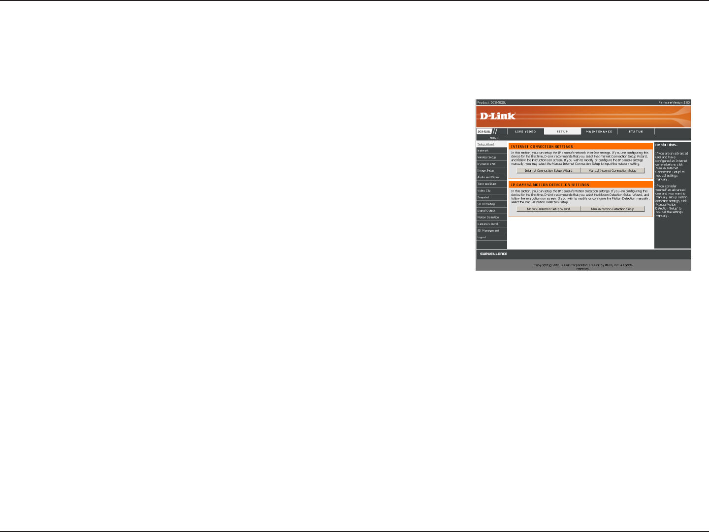
Setup
The setup wizard guides you through the initial setup of your IP camera. You
can use the Internet Connection Setup Wizard for initial network setup,
and you can use the Motion Detection Setup Wizard to set up motion
detection. Simply follow the instructions given in each step of the wizard to
quickly set up your camera.
Alternatively, you can manually set up your Internet connection by clicking
Manual Internet Connection Setup, and you can manually set up motion
detection options by clicking on Manual Motion Detection Setup. You can
also see these settings by clicking on the menu on the left panel (Network
Setup / Wireless Setup / Motion Detection / Snapshot).
Wizard
25D-Link DCS-5222L/DCS-5211L User Manual
Section 4 - Configuration
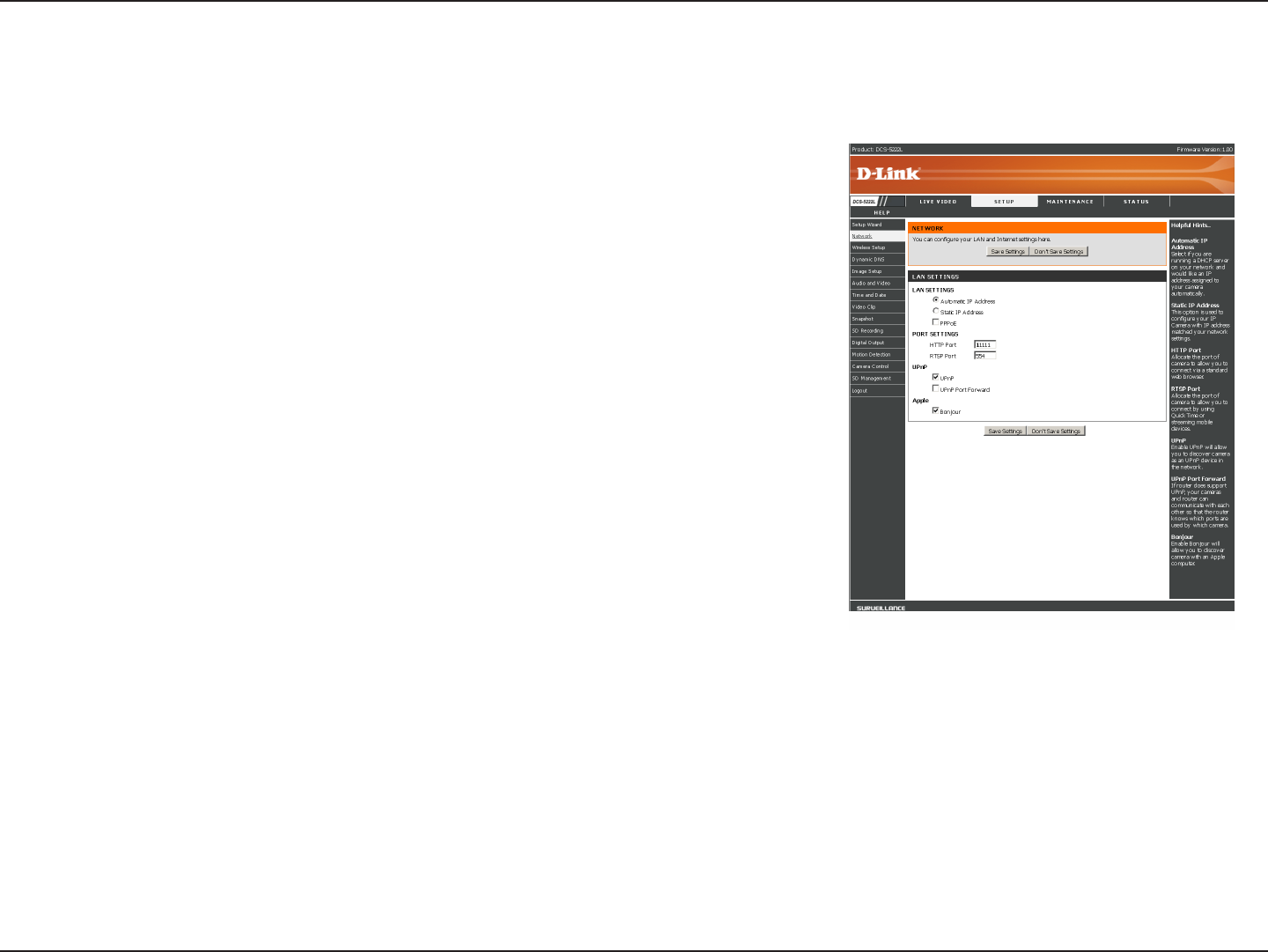
This section allows you to congure your LAN and Internet conguration.
Automatic IP Address Select: This option is used if you are running a DHCP
server on your network and would like an IP address assigned to your camera
automatically by the DHCP server. If the DHCP server does not exist the IP camera
will run with an auto address of 169.254.xxx.xxx, you may need to manually
congure this setting should no DHCP server exist.
Static IP Address: This option is used to congure your IP Camera with an IP
address which matches your network settings.
HTTP Port: This option allocates the HTTP port of the camera, allowing you to
connect via a standard web browser, in this example picture (right) the port is
set to 1111. The address used in a web browser could be (depending on the IP
settings used in your network)192.168.0.20:1111.
RTSP Port: This option allocates the RTSP port of the camera, the RSTP port
allows connections using QuickTime or other streaming mobile devices.
UPnP Enable: UPnP (Universal Plug & Play) can be used to allow discovery of a
camera as a UPnP device in the network, without additional conguration.
UPnP Port Forward: If the router being used supports UPnP, your camera and
router can communicate allowing the router to discover which ports are used
by each camera.
Bonjour: Enabling Bonjour will allow discovery of cameras by Apple computers.
Note: If you need to use a static IP address and you do not know the network information, contact your Internet Service
Provider (ISP) for assistance.
Network Setup

26D-Link DCS-5222L/DCS-5211L User Manual
Section 4 - Configuration
Note: You MUST also set up your router/gateway for Port Forwarding/Mapping; this will enable remote viewing
of your camera via the Internet. Please refer to your router’s instruction manual on how to open up ports. For
additional help on configuring your camera to work with your router, please refer to Appendix A: Installing the
DCS-5222L/DCS-5211L on a Router Without UPnP. For installing multiple cameras, ONE port per camera must be
opened on your router, the Web server (HTTP) port. Also, some browsers may restrict some ports, such as 1 or 22,
for security purposes. If you have problems accessing your camera through HTTP, try using a port higher than 1024.
After making any changes, click the Save Settings button to save your changes, or click the Don’t Save Settings button
to discard your changes.
27D-Link DCS-5222L/DCS-5211L User Manual
Section 4 - Configuration
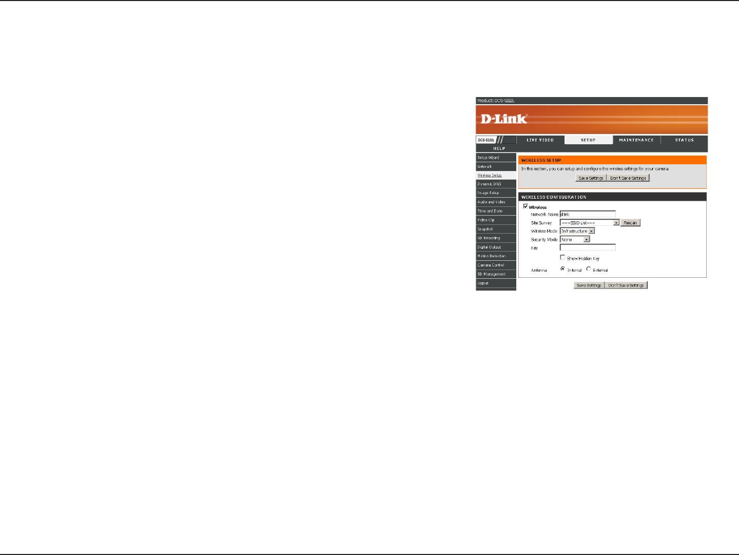
Site survey: Click the Rescan button to scan for available wireless networks. After scanning,
you can use the drop down box to select an available wireless network. The related information
(SSID, Wireless Mode, Channel, Authentication, Encryption) will be automatically lled in for
you.
SSID: The SSID of the wireless access point you wish to use.
Wireless Mode: Use the drop down box to select the mode of the wireless network you
wish to connect to. Infrastructure is normally used to connect to an access point or router.
Ad-Hoc is usually used to connect directly to another computer.
Channel: If you are using Ad Hoc mode, select the channel of the wireless network you wish
to connect to, or select Auto.
Authentication: Select the authentication you use on your wireless network - Open, Shared
(WEP), WPA-PSK, or WPA-PSK2.
Encryption: If you use WPA-PSK or WPA-PSK2 authentication, you will need to specify whether your wireless network uses TKIP or
AES encryption. If you use Open or Shared authentication, this setting will be automatically set for you.
Key: If you use WEP, WPA-PSK, or WPA-PSK2 authentication, enter the Key (also known as password) used for your wireless
network.
After making any changes, click the Save Settings button to save your changes, or click the Don’t Save Settings
button to discard your changes.
Wireless
To set up your IP camera’s wireless network interface settings, enable Wireless Settings in this window rst. Then
continue the further conguration next.
28D-Link DCS-5222L/DCS-5211L User Manual
Section 4 - Configuration
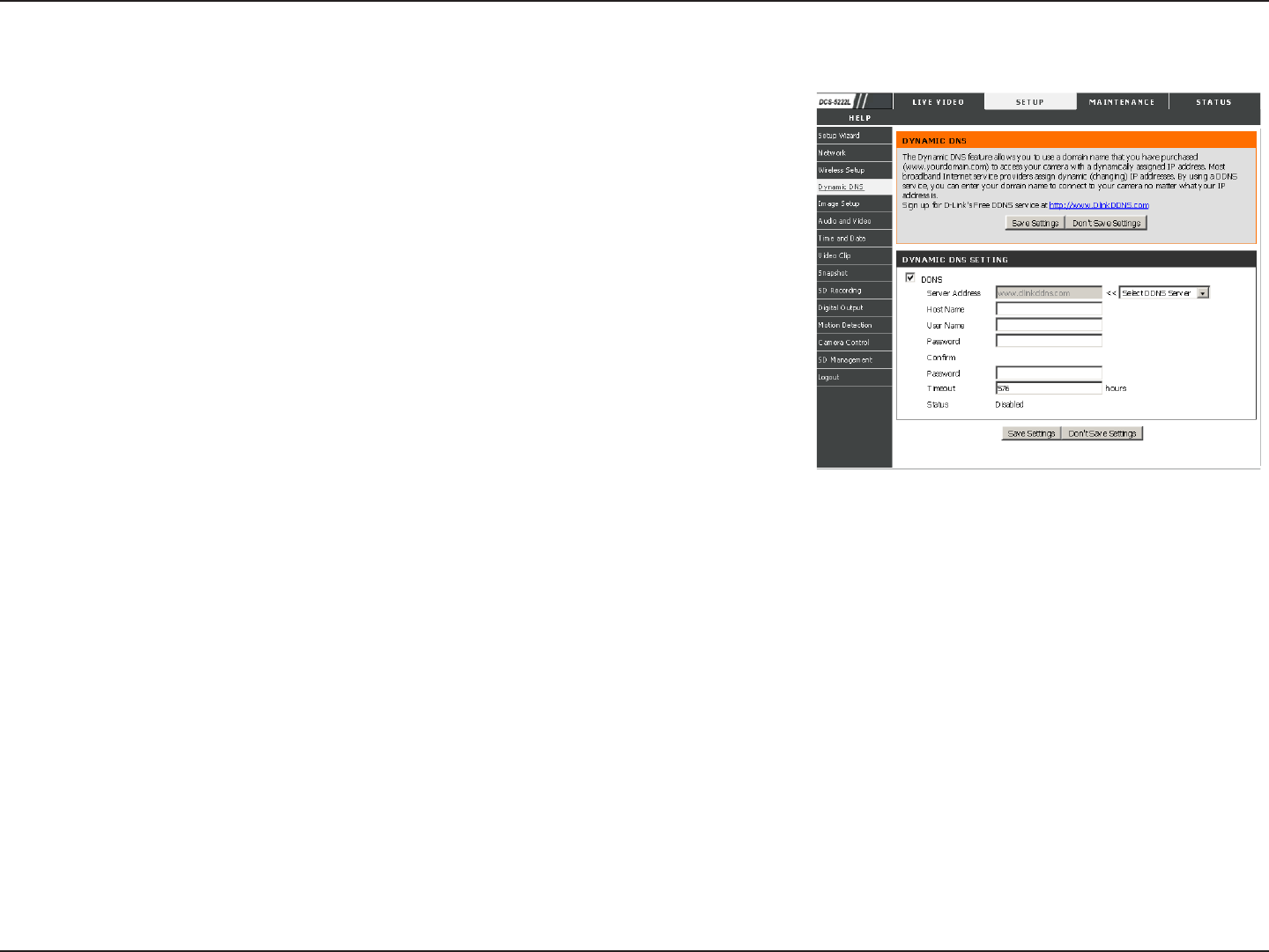
If you have a DSL or Cable service provider that changes your modem IP address
periodically, Dynamic DNS (Domain Name Service), a method of keeping a
domain name linked to a dynamic IP address, is useful. With most Cable and DSL
connections, you are assigned a dynamic IP address and that address is used only
for the duration of that specic connection. With the DCS-5222L/DCS-5211L, you
can set up your DDNS service and the DCS-5222L/DCS-5211L will automatically
update your DDNS server every time it receives a dierent IP address. Depending
on the service, this update may take a few hours.
Enable DDNS: Check this checkbox to enable the DDNS function of the camera.
Server Address: Use the drop down box on the right to select a DDNS service.
Host Name: Type in the Host Name of the DDNS service.
User Name: Enter your User Name for the DDNS service.
Password: Enter the password for the DDNS service.
Conrm Password: Retype the password for the DDNS service.
Timeout: This sets the number of hours between DDNS updates.
Status: Provides a status of enabled or disabled
After making any changes, click the Save Settings button to save your changes, or click the Don’t Save Settings
button to discard your changes.
Dynamic DNS
29D-Link DCS-5222L/DCS-5211L User Manual
Section 4 - Configuration
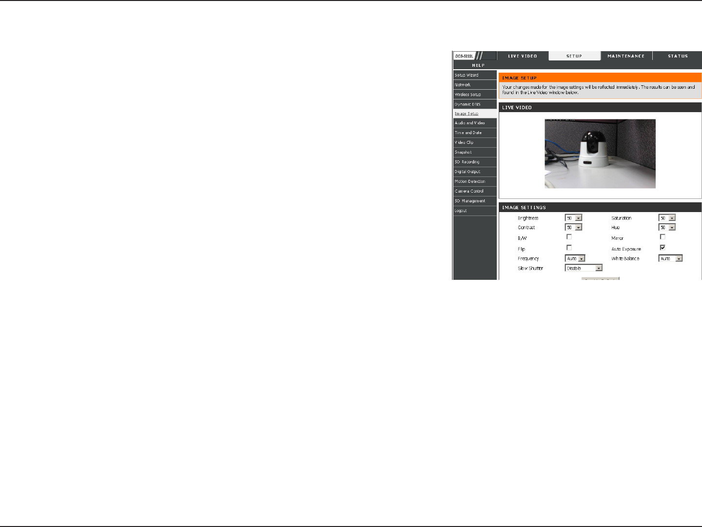
The options in Image Setup allow you to adjust the settings for your IP
camera sensor and image.
Brightness: This adjusts the brightness of the camera image. This is set to 50 by default.
Saturation: This adjusts the color saturation. Saturation controls the strength of color in the
image. This is set to 50 by default.
Contrast: This adjusts the contrast of the camera image, making a dull image sharper or a
bright image smoother. This is set to 50 by default.
Hue: The Hue controls the dierent degree of color stimulation in the camera image. This is
set to 50 by default.
Frequency: This option adjusts the camera sensor’s setting to avoid the image ickering under
certain light sources, such as orescent lights. This is set to Auto by default.
White balance: You can change the white balance of the camera image by selecting a setting
from the drop down box. This is set to auto by default.
B/W: Ticking this checkbox will change the camera image into black and white.
Flip: This will ip the image vertically.
Mirror: This will ip the image horizontally in such a way that your left side will be on the left side of the screen and vice versa.
Slow shutter: This can be used to allow manual control of the shutter speed. Select slower shutter speeds when environment is dimly lit, faster
speeds are required when in brighter lighting.
Note: Mirror and Flip can be used if you choose to mount the DCS-5222L/DCS-5211L upside down on the ceiling.
Image Setup
30D-Link DCS-5222L/DCS-5211L User Manual
Section 4 - Configuration
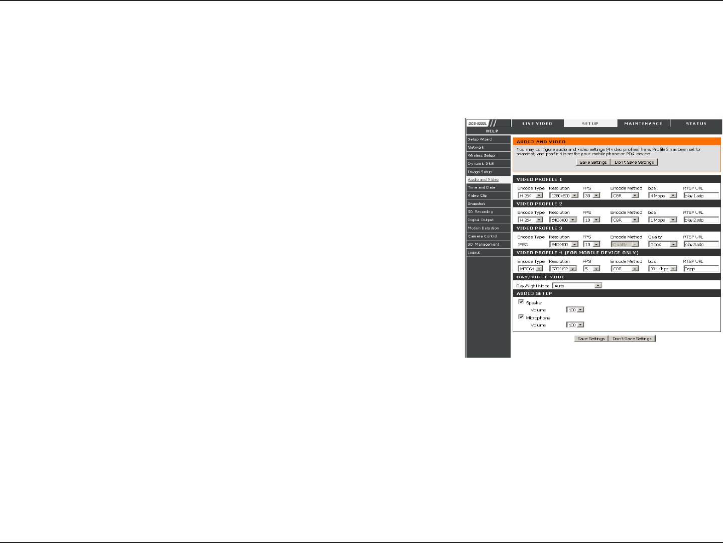
Encode Type: This sets the video codec used for the video stream. You can choose
H.264, MPEG4 or MJPEG(JPEG). Internet Explorer browsers can view both H.264, MPEG4
or MJPEG(JPEG) video streams, and non-IE browsers can only view MJPEG video streams.
Resolution: This sets the display resolution of the video stream. If the Resolution is
dierent than the Sensor Output size, the video will be shrunken or enlarged to the
Resolution size you set here.
FPS: This sets the target number of frames per second (FPS) for the video stream.
Higher frame rates will provide smoother video, lower frame rates will use less network
bandwidth.
bps: This sets the target bit-rate of the video stream. Higher bit-rates will provide better
quality video but could result in slower network transfers. When the Encode Type is
set to MJPEG, you will be unable to change the bps setting. Available bps settings may
also change depending on what the Encode Type, Sensor Output, Resolution, and FPS
settings are set to.
RTSP URL: This setting allows you to set a sux for your camera’s RTSP URL, allowing
the camera’s video to be viewed with this video prole’s settings. For example, if “mpeg4” is used as the RTSP URL setting and the camera’s IP is
192.160.0.20, the camera’s video can be viewed with these settings using 192.160.0.20/mpeg4.
Note: Video Profile 3 is always set to MJPEG as the Encode Type to ensure that at least one of the Video Profiles
are viewable by non-IE browsers. Video Profile 4 is for mobile devices only, and always uses MPEG-4 as the Encode
Type.
Audio and Video
You may congure four video proles with dierent settings for your camera. You may also set up dierent proles for
your computer and mobile display. In addition, you may congure the audio (speakers and microphone) settings for
your camera. There are three sensor output selections (VGA, XGA, and SXGA). Do not select SXGA if you want to
turn on the motion detection feature.

31D-Link DCS-5222L/DCS-5211L User Manual
Section 4 - Configuration
Day/Night Mode: Four options are available via the drop down menu. Auto lets the camera select use of or non-use of IR LED’s in a low light area.
Manual IR mode allows the user to manually select Day/Night mode. Always Day and Always Night force the camera into either Day or Night mode.
Note that the live video will turn to black and white mode when IR LEDs turned on.
Speaker: Checking this box will allow you to talk using the PC’s microphone. The drop down menu allows volume control.
Microphone: Checking this box will enable listening to audio captured by the camera’s microphone. The drop down menu allows volume control.
Note: Higher frame size, frame rate and bit rates will give you better video quality, but they will also require more
network bandwidth. For best viewing results on a mobile phone, we suggest setting the frame rate to 5 fps and the bit
rate to 20 Kbps.
After making any changes, click the Save Settings button to save your changes, or click the Don’t Save Settings
button to discard your changes.
32D-Link DCS-5222L/DCS-5211L User Manual
Section 4 - Configuration
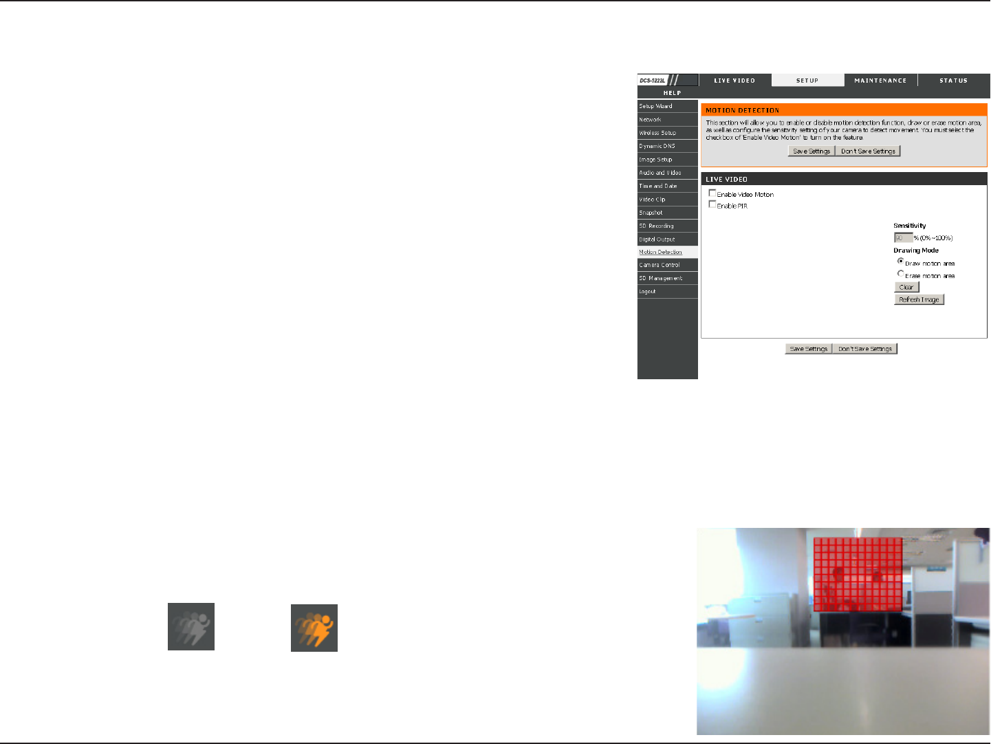
Motion Detection
Tick this box to enable the PIR sensor.
Tick this box to enable video motion detection.
This setting adjusts how sensitive the camera will be to motion,
where 100% will be the most sensitive setting and 0% will be the least
sensitive setting.
This will allow you to draw motion detection zones when clicking
and dragging, or erase motion detection zones when clicking and
dragging depending on which option you have selected.
Clicking this button will clear all motion detection zones.
After making any changes, click the Save Settings button to save your changes, or click the Don’t Save Settings button
to discard your changes.
Note: If the camera is set to SXGA mode in Audio and Video, Motion Detection is disabled.
This option allows you to set up Motion Detection on your IP camera. In order to
use motion detection first check the Enable Video Motion checkbox. Next, click
on the video window and draw motion detection zones by clicking and dragging
the mouse cursor. Red areas indicate areas that will be monitored for motion.
The camera also has a PIR sensor which is used to detect motion using a special
infrared sensor. PIR is good at detecting motion from live subjects such as people
and animals.
Enable PIR:
Enable Video Motion:
Sensitivity:
Draw Motion Area:
Erase Motion Area:
The motion notication will continue to blink as long as motion is detected. If no additional
motion is detected, it will return to its original state after eight seconds.
The red grid on the right indicates an area that has been selected for motion detection.
When motion is detected, the LIVE VIDEO page will display a blinking orange motion video
icon like the one below.
No Motion Motion
33D-Link DCS-5222L/DCS-5211L User Manual
Section 4 - Configuration
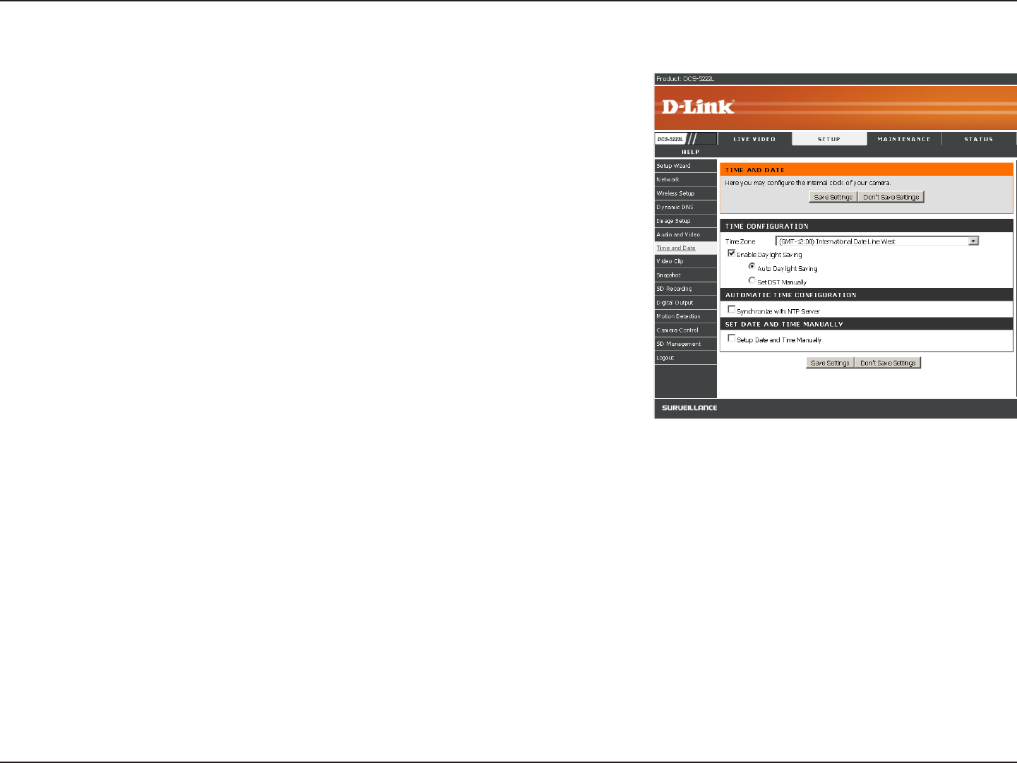
Time and Date
This option allows you to congure, update, and maintain the correct time on
the internal system clock. From this section you can set the time zone that you
are in and set the NTP (Network Time Protocol) Server. Daylight Saving can also
be congured to automatically adjust the time when needed.
Time Zone: Select your time zone from the drop down menu.
Enable Daylight Saving: If your region uses a Daylight Saving adjustment, check this
checkbox.
Auto Daylight Saving: This option will adjust Daylight Saving Time automatically.
Set date and time manually: Selecting this will let you set the Daylight Saving Time
adjustment manually:
• Daylight Saving Offset: This will set the Daylight Saving adjustment that will be used.
• Daylight Saving Date: This will set the beginning and ending dates of the Daylight
Saving period.
You can also have the camera’s clock set automatically, or manually.
Synchronize with NTP Server: Checking this checkbox will allow the camera to synchronize its clock with an NTP server.
NTP Server: Use the drop down box to the right to select an NTP server to use, or you can type one in.
Set date and time manually: Check this checkbox to set the time and date manually. You can then use the drop down boxes to select the
current Year, Month, Day, Hour, Minute, and Second. You can also click the Copy Your Computer’s Time Settings button to
automatically ll in the drop down boxes with the current time and date from your computer.
After making any changes, click the Save Settings button to save your changes, or click the Don’t Save Settings button
to discard your changes.
34D-Link DCS-5222L/DCS-5211L User Manual
Section 4 - Configuration
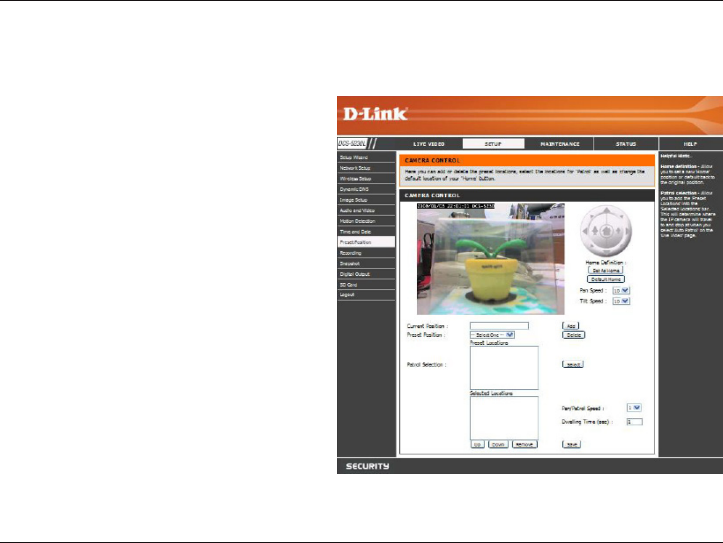
Camera Control
Click the Preset Position button from the left side of the Setup screen to access settings that aect how the DCS-5222L
Internet Camera can pan and move to preset locations.
Select the speed at which the camera will
pan for a full cycle from the drop-down list.
Select a value between 0 and 10, 0 being the
slowest setting.
Select the speed at which the camera will
tilt for a full cycle from the pull down menu.
Select a value between 0 and 10, 0 being the
slowest setting.
Enter a name for the position at which you would
like to preset the DCS-5222L. Click add to add the
new preset position to the Preset Locations list
.
Using the drop-down list, you can choose and
delete a preset position by selecting it and
clicking Delete.
Pan Step
Tilt Step:
Present Position:
Preset Position:

35D-Link DCS-5222L/DCS-5211L User Manual
Section 4 - Configuration
Use the Set As Home button to set the current position as the home position. The Home position is the rst
position the camera goes to after the camera boots. You can also recall the default home position, use the
Default Home button.
To use the Auto Patrol feature, select the desired preset positions from the Preset Locations list and add
them to the Selected Locations list by clicking Select. You can then select the order in which the camera will
patrol through the preset locations by selecting a location and clicking Up or Down. Click Remove to remove
a location from the list.
Set as Home:
Patrol Selection:
36D-Link DCS-5222L/DCS-5211L User Manual
Section 4 - Configuration
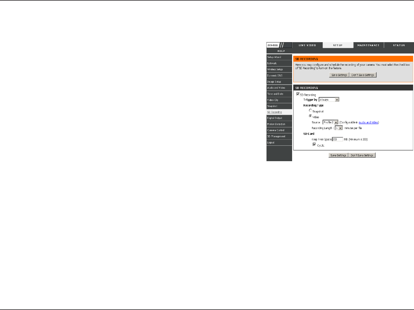
This option allows you to congure recording settings and scheduling. You
can record video to a Samba network drive on your local network.
Enable recording: Check this checkbox to enable the recording feature. After enabling
recording, you will need to select a scheduling method.
SD Card: Select this option if you have inserted an available SD card into the camera.
Trigger byMotion: Trigger byMotion begins SD recording after a motion is detected.
Schedule SD recording in a specied time.
Recording Type: It is possible to set the recording codec, set pre-event recording, and post-
event recording here when Trigger by is activated. You can also select recording as Snapshot
or Video.
Recording Length: Use this to set the time length of each recording video.
Keep Free Space: This sets the capacity of your local SD Card to prevent the system from becoming unstable.
Cyclic: When this option is selected, it will cause the oldest folder to be deleted when the system requires storage space for new les.
SD Recording
37D-Link DCS-5222L/DCS-5211L User Manual
Section 4 - Configuration
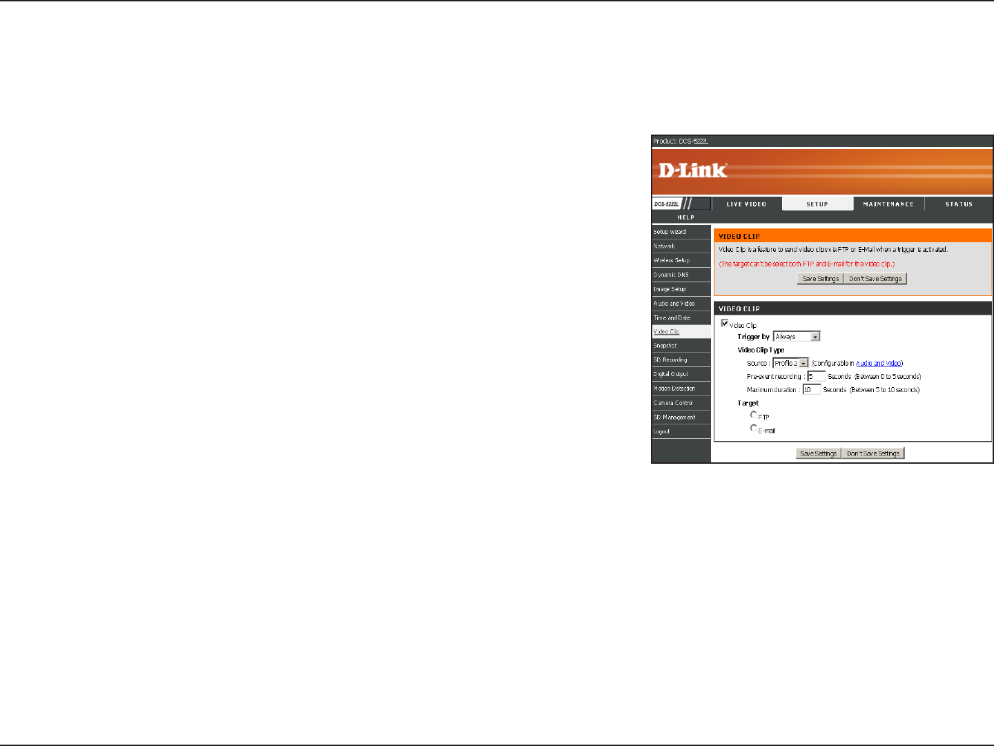
Video Clip
Video Clip is the ability to store or send video clips to a remote E-mail or FTP server based on motion detection, external
sensor input triggered.
Trigger by Motion: This begins video clipping after a motion is detected. It is possible to
schedule video clipping at a specied time, continuously or after digital input is detected. Use
the drop down menu to congure appropriate mode.
Video Clip Type: The video clip type can be set to video clip codec, Pre-event recording and
Maximum duration here.
Pre-event recording: It is possible to specify how many seconds of video will be recorded,
before the video clip is taken.
Maximum duration: This species how many seconds of video clipping is taken.
Target it is possible to select the target as FTP or E-mail for the video clipping.
38D-Link DCS-5222L/DCS-5211L User Manual
Section 4 - Configuration
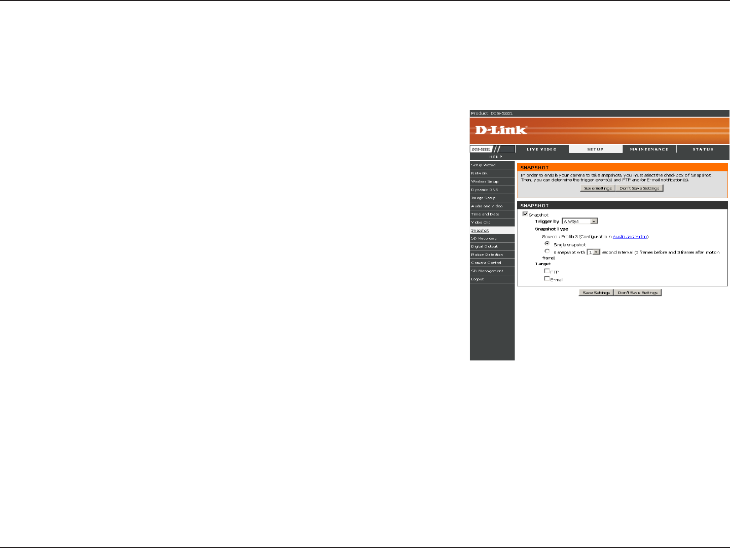
Here, you can set the camera to take snapshots when motion is detected. Snapshots can be sent to an e-mail address
and/or to an FTP server.
Trigger by: The motion drop down menu selection begins snapshot after a motion is
detected. Schedule Snapshot schedules the snapshot at a specied time. Always Continuous
Snapshot provides continuous snapshots. Digital Input begins taking snapshots after a digital
input is detected.
Snapshot Type: It is possible to set snapshot codec from Prole 3(JPEG), Single snapshot
or 6 snapshot here.
6 snapshot: Select this option to take continuous 6 pictures for each snapshot.
Target: It is possible to select the target as FTP or E-mail for the snapshot.
Snapshot
39D-Link DCS-5222L/DCS-5211L User Manual
Section 4 - Configuration
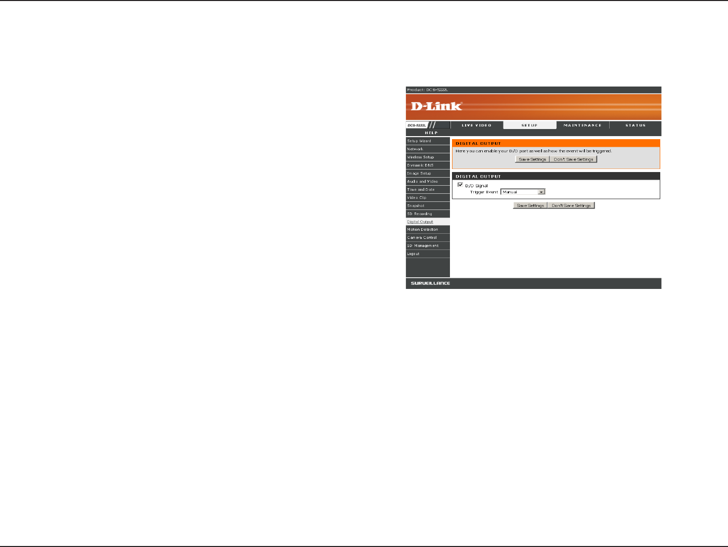
Digital Output
You can enable the digital output port as well as congure the trigger event.
Motion Detection: When a motion detection is triggered.
D/I Signal: A trigger from the Digital Input port.
40D-Link DCS-5222L/DCS-5211L User Manual
Section 4 - Configuration
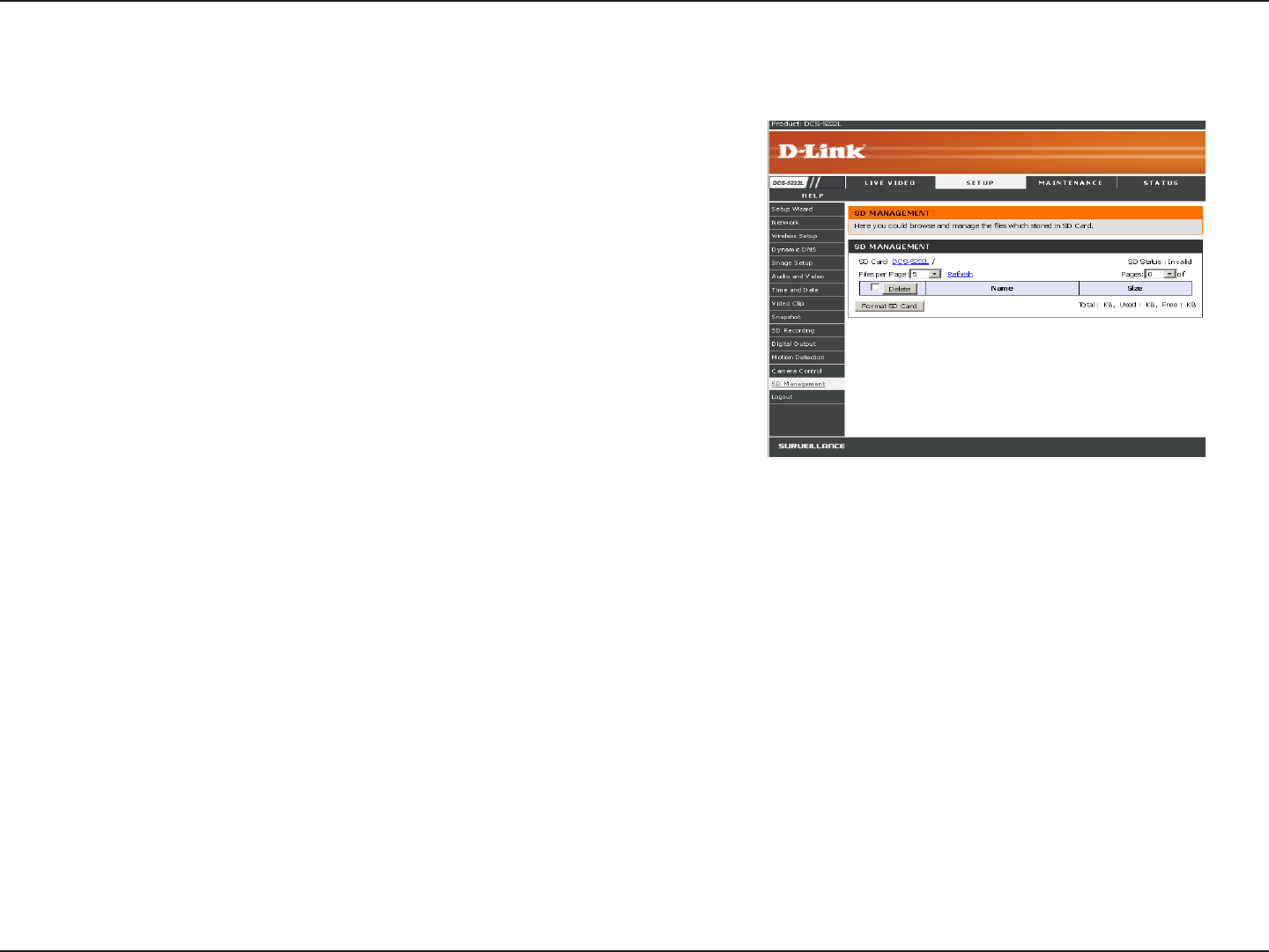
Format SD Card: To format the SD card. Delete all data from the SD card.
Name: The name of le or catalog.
Num of les: The amount of les in catalog.
Size: The le’s size.
Refresh: Click it reload data to webpage.
Top Level: Click it go back to previous level.
Delete: Click this button to select all the les below.
OK: Click this button to delete the selected les above.
Clicking “Format SD Card” will delete all data from the SD card,
and create folder for video.
SD Management
41D-Link DCS-5222L/DCS-5211L User Manual
Section 4 - Configuration
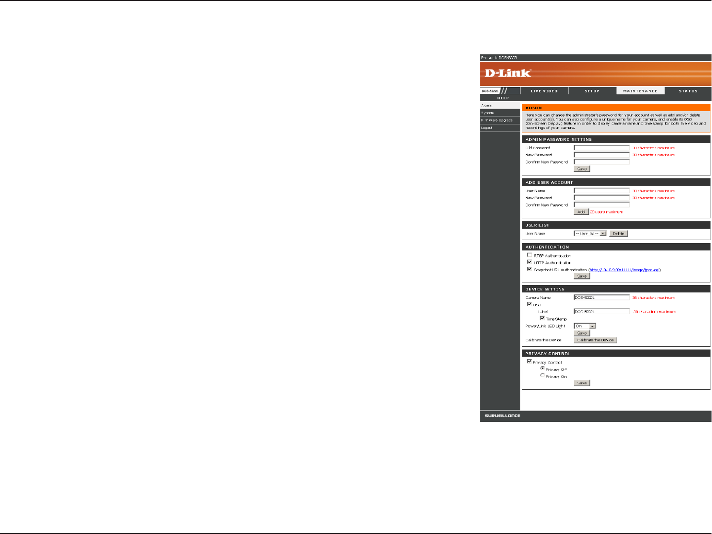
Here you can change the Admin password, add and manage Users, and adjust some
camera settings.
Admin Password Setting: This section lets you change the admin password used to log in to the
camera and adjust settings. After installing the camera for the rst time, it is highly recommended
that you change the admin password for security purposes.
New Password: Enter the new admin password.
Retype Password: Enter the new admin password again for verication. After entering the new
password again, click on the Save button to save your changes.
Add User Account: Admin can create user accounts to allow others to log in to your camera to
view the live camera feed.
User Name: Enter the User Name you wish to use for the new user account.
New Password: Enter the password for the new user account.
Retype Password: Re-enter the password for the new user account for verication. After entering
the password again, click Add to add the new user account.
User List: Here, you can view the current list of users by using the drop down box. You can also
delete a user by selecting them with the drop down box, and then clicking the Delete button.
Device Setting: Here, you can change various other settings for your camera.
Camera Name: Enter the name of your camera.
Enable OSD: This will enable the information bar On Screen Display (OSD) to appear when viewing
video.
Label: This is the text label that will appear on the OSD.
Show time: If checked, the current time will be displayed on the OSD.
LED light: This will turn the camera’s front LED indicator on or o.
Calibrate the Device: Clicking this button will calibrate the camera so that the P/T/Z apparatus functions correctly. The camera is automatically
calibrated whenever it is powered on and initialized or reset. Should the camera’s pan, tilt, and zoom functions begin to behave incorrectly, or if
the device has been jarred or handled improperly, you may need to recalibrate the camera manually by pressing this button.
Privacy Mode: Select on/o or schedule the privacy mode for your camera to ensure the privacy. When the privacy mode is turned on, the camera
hides the lens by rolling it back into the unit.
After making any changes to this section, click the Save button to save your changes.
Maintenance
Admin
42D-Link DCS-5222L/DCS-5211L User Manual
Section 4 - Configuration
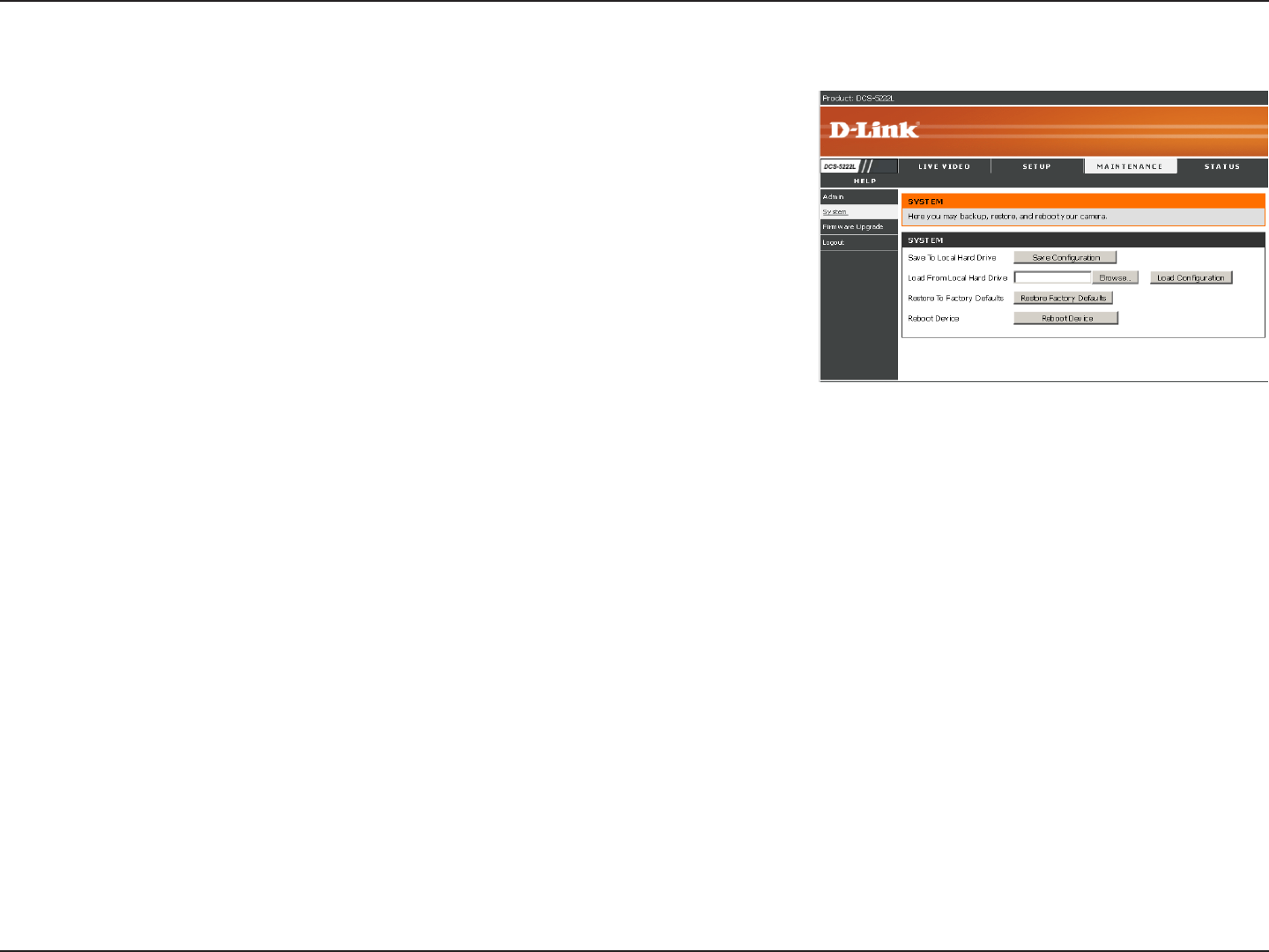
System
This screen allows you to save and restore the camera’s current conguration.
You can also reset all settings to factory default or reboot the device.
Save To Local Hard Drive: Click on the Save Conguration button to save the current
conguration to a hard drive.
Load From Local Hard Drive: To load a saved conguration, click on the Browse button
to select a conguration le from your hard drive. Then, click the Load Conguration
button to load the new conguration.
Restore To Factory Defaults: Click this button to reset all settings to their factory
defaults. If you choose to reset your settings, you will need to set up your camera again.
Reboot Device: Clicking the Reboot button will reboot your device.
43D-Link DCS-5222L/DCS-5211L User Manual
Section 4 - Configuration
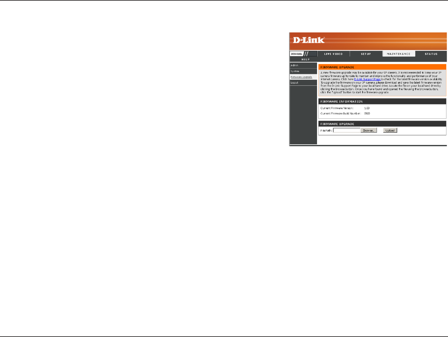
Firmware Upgrade
Your current firmware version and date will be displayed on this
page. Here, you can also upgrade your firmware with a new version.
Firmware upgrades are made available at support.dlink.com.
To upgrade your firmware, go to support.dlink.com.tw and download
the latest rmware to your computer’s hard drive. Click on Browse, select
the rmware le, then click the Upload button. While the rmware is being
upgraded, do not turn o your computer or camera, and do not disconnect
your network connection from your computer or camera. Upgrading the
rmware will not change any of your system settings, but it is recommended
that you save your system conguration before doing a rmware upgrade.
Note: It is recommended that you use a wired connection for your computer and camera when upgrading the
firmware.
44D-Link DCS-5222L/DCS-5211L User Manual
Section 4 - Configuration
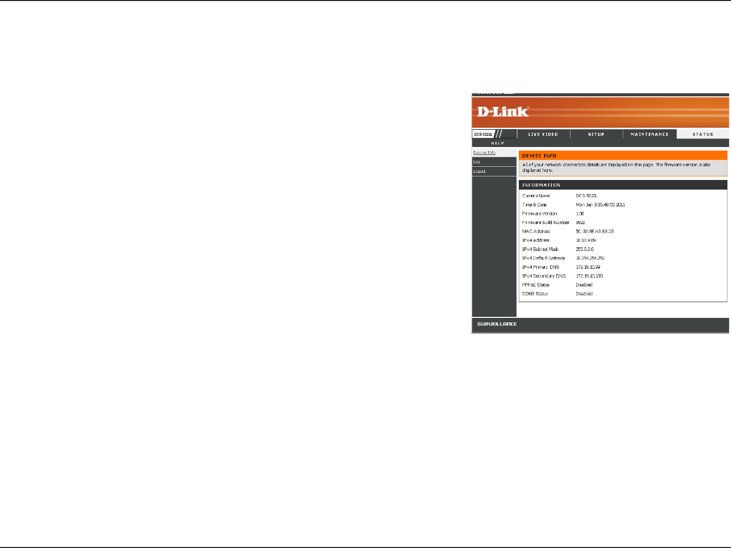
Status
This screen shows you various information about your camera and its
current settings.
Device Info
45D-Link DCS-5222L/DCS-5211L User Manual
Section 4 - Configuration
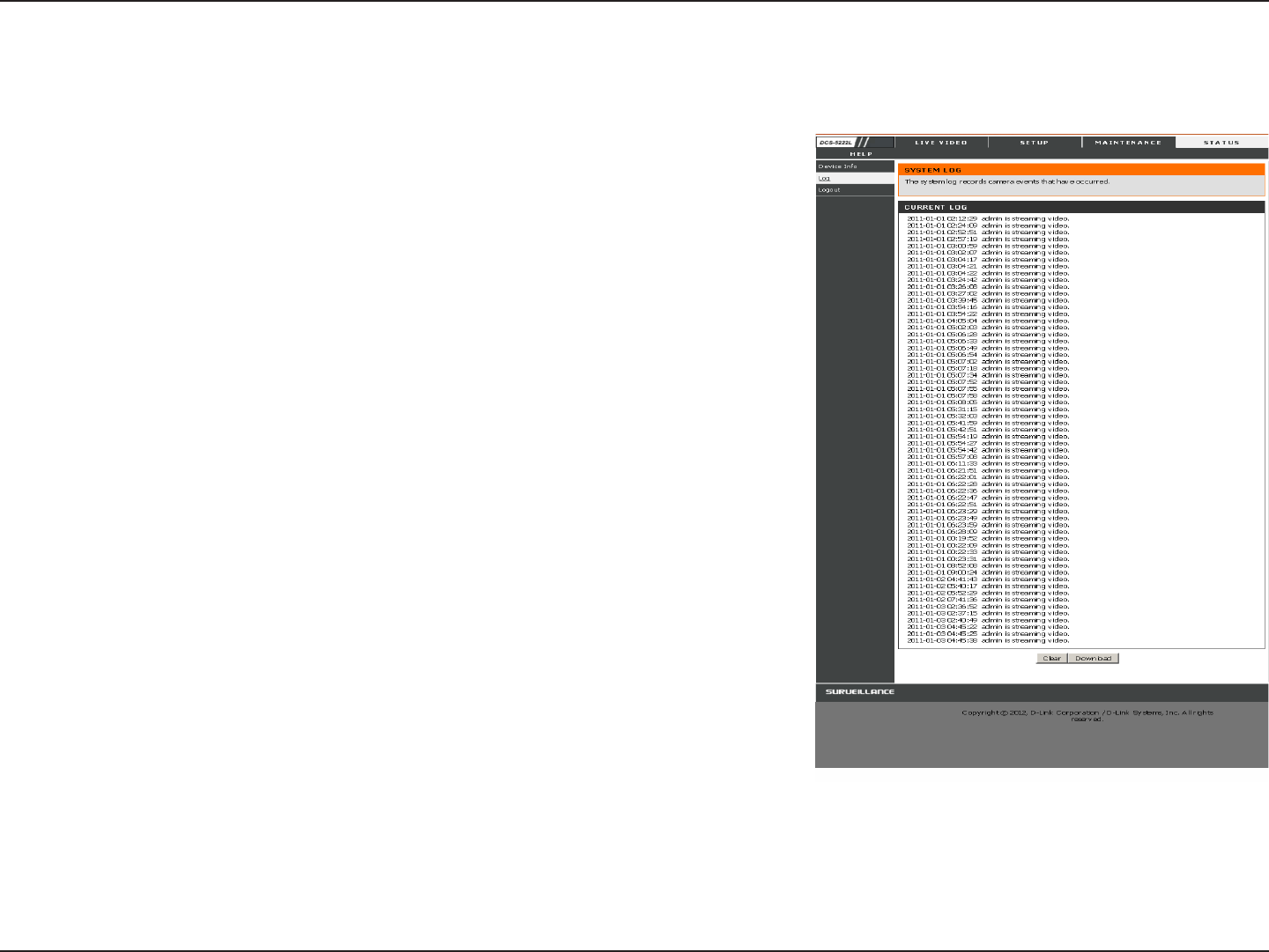
The log shows you a list of events that have happened recently. You can
download the log by clicking the Download button, or you can empty the
log by clicking the Clear button.
Log
46D-Link DCS-5222L/DCS-5211L User Manual
Section 4 - Configuration
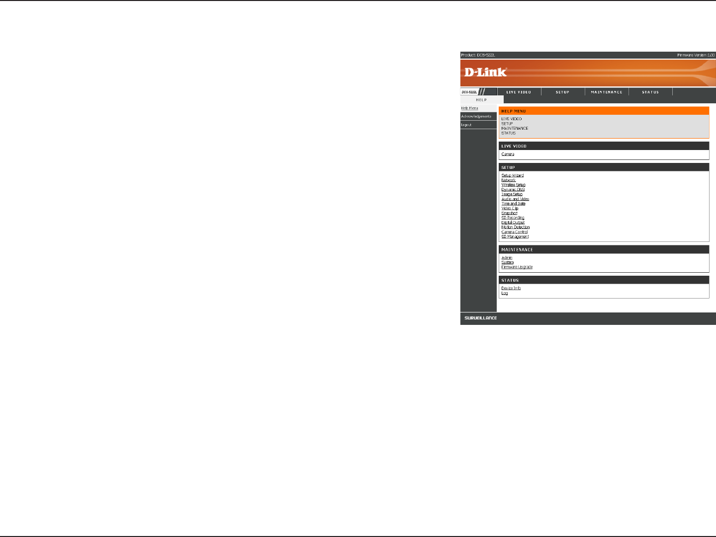
Help
The Help screen provides you with support information about the
DCS-5222L/DCS-5211L for your reference.
1. Why can’t I access the web-based conguration utility?
When entering the IP address of the D-Link router (192.168.0.1 for example),
you are not connecting to a website on the Internet or have to be connected to
the Internet. The device has the utility built-in to a ROM chip in the device itself.
Your computer must be on the same IP subnet to connect to the web-based
utility.
• Make sure you have an updated Java-enabled web browser. We recommend
the following:
• Internet Explorer 6.0 or higher
• Firefox 1.5 or higher
• Netscape 8 or higher
• Mozilla 1.7.12 (5.0) or higher
• Opera 8.5 or higher
• Safari 1.2 or higher (with Java 1.3.1 or higher)
• Verify physical connectivity by checking for solid link lights on the device. If you do not get a solid link light, try using a
dierent cable or connect to a dierent port on the device if possible. If the computer is turned o, the link light may not
be on.
• Disable any Internet security software running on the computer. Software rewalls such as Zone Alarm, Black Ice,
Sygate, Norton Personal Firewall, and Windows® rewall may block access to the conguration pages. Check the
help les included with your rewall software for more information on disabling or conguring it.

47D-Link DCS-5222L/DCS-5211L User Manual
Section 5 - Troubleshooting
• Congure your Internet settings:
• Go to Start > Control Panel. In Windows® XP or Windows Vista™, make sure you are in Classic View. Double-click
the Internet Options Icon. From the Security tab, click the button to restore the settings to their defaults.
• Click the Connection tab and set the dial-up option to
Never Dial a Connection
. Click the LAN Settings
button. Make sure nothing is checked. Click OK.
• Go to the Advanced tab and click the button to restore these settings to their defaults. Click OK three times.
• Close your web browser (if open) and open it.
• Access the web management. Open your web browser and enter the IP address of your D-Link router in the address bar. This
should open the login page for your the web management.
• If you still cannot access the conguration, unplug the power to the router for 10 seconds and plug back in. Wait about 30
seconds and try accessing the conguration. If you have multiple computers, try connecting using a dierent computer.
2. What can I do if I forget my password?
If you forget your password, you will need to perform a hard reset of your camera. This process will change all your settings
back to the factory defaults.
To reset your camera, please use an unfolded paperclip to press and hold the RESET button for at least 6 seconds while your
camera is plugged in.

48D-Link DCS-5222L/DCS-5211L User Manual
Section 5 - Troubleshooting
Troubleshooting
1. What can I do if I forget my password?
If you forget your password, you will need to perform a hard reset of your camera. This process will change all your
settings back to the factory defaults.
To reset your camera, please use an unfolded paperclip to press and hold the RESET button for at least 6 seconds
while your camera is plugged in.
Please note that this will also remove the camera from your mydlink account, so you will need to add it back to your
account later.
2. In addition to using mydlink.com, is there another way to access my camera remotely over the Internet?
Yes, you can access your camera over the Internet through the following URL after successfully installing your camera
through the Camera Setup Wizard:
http://[mydlink No.].dev.mydlink.com
For example, if your camera’s mydlink No. was 12345678, you would be able to access your camera remotely
by opening your web browser and going to http://12345678.dev.mydlink.com
This URL will open your camera’s web interface, where you can sign in and congure your camera’s settings.
49D-Link DCS-5222L/DCS-5211L User Manual
Section 5 - Troubleshooting
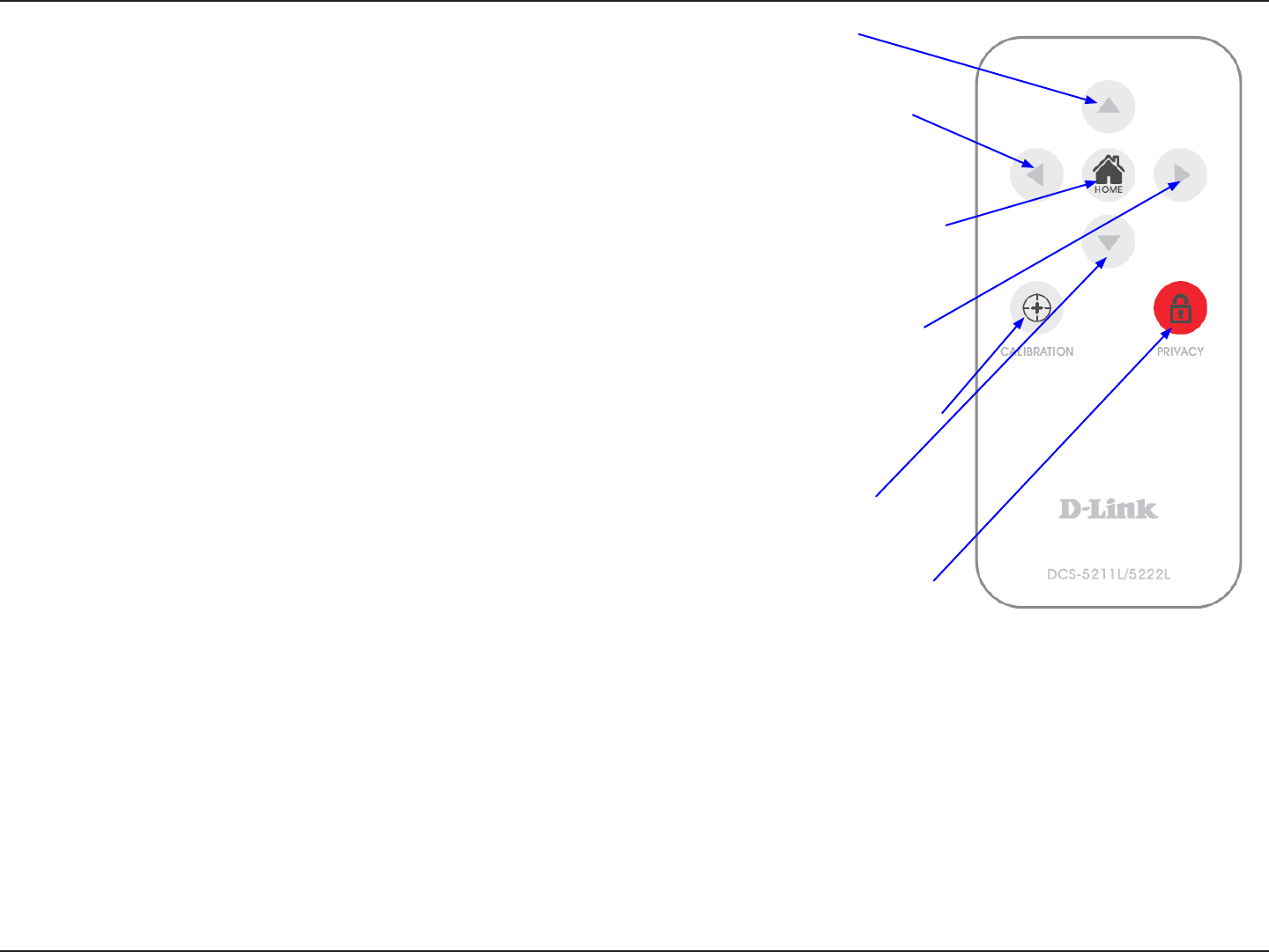
Technical Specifications - Remote Control Unit
Feature
• Remote Controller : 3x3 key matrix
• Code system: NEC
• IR transmitter frequency: 38KHz
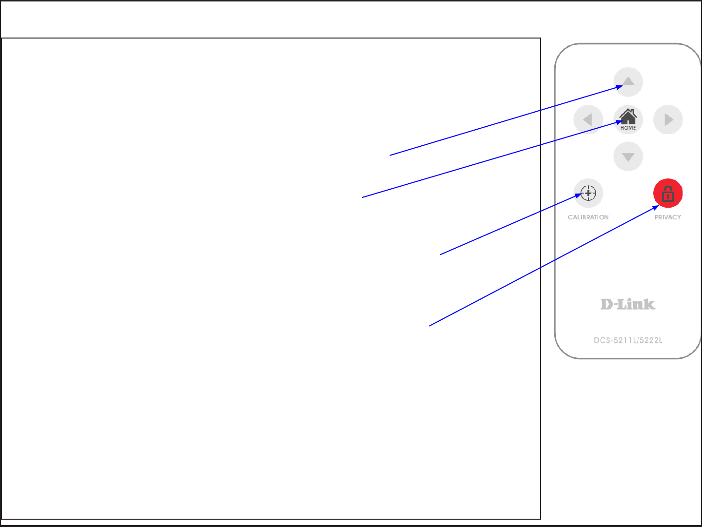
• Outline drawing below:
Pan/ tilt direction key
Pressing pan/tilt direction key will move camera to the direction for a few steps.
Home key
Pressing Home key will move camera to the home position, i.e., the center
position calibrated last time or the position set by user.
Calibrate key
Pressing Calibrate key will do calibration of both pan and tilt position by moving from end
to end where a position sensor is located and go to the corrected home position.
Privacy key
Pressing privacy key will tilt to privacy position where camera is hidden in cover (privacy
mode). Pressing again privacy key in privacy mode will tilt back to the previous position.
50D-Link DCS-5222L/DCS-5211L User Manual
Section 5 - Troubleshooting
Matrix Index Key Name Key Code Function
(1,2) ...................................................................................................................................... Up 44 Tilt move up
(2,1) ..................................................................................................................................... Left 4C Pan move to the left
(2,2) ................................................................................................................................ Home 06 Return to home position
(2,3) ................................................................................................................................. Right 40 Pan move to the right
(3,1) .......................................................................................................................... Calibrate 07 Calibrate home position
(3,2) ................................................................................................................................ Down 48 Tilt move down
(3,3) .............................................................................................................................. Privacy 0E Tilt to privacy position.
51D-Link DCS-5222L/DCS-5211L User Manual
Section 5 - Troubleshooting
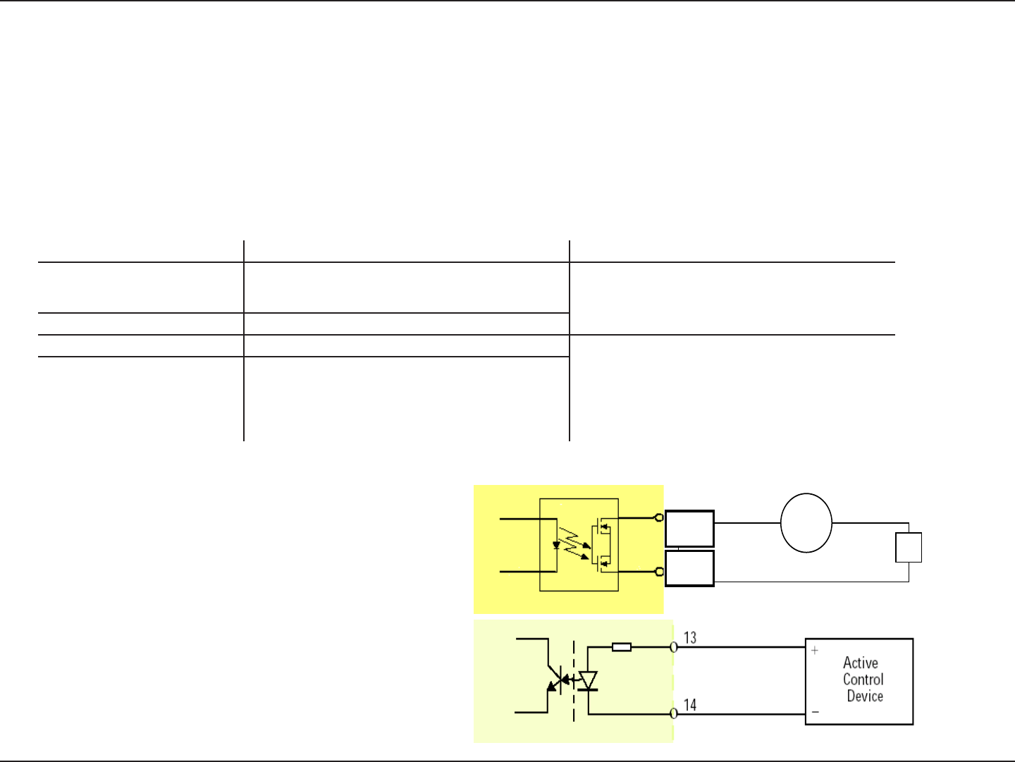
Technical Specifications - I/O Terminal Application
Typically used in association with programming scripts for developing applications for motion detection, event triggering, alarm notication via
e-mail, and a variety of external control functions. The 4-pin I/O Terminal Block is located on the rear panel and provides the interface of a photo-
coupled switch output and a photo-coupled input.
Connector Pin Assignment
Sign FUNCTION SPECIFICATION
DO- Photo-Relay OUTPUT (Normal Open) Close circuit current max. 70 mA AC, or 100 mA DC.
On-Resistance max. 30 Ohm.
Open circuit blocking voltage
max. 240VAC or 340VDC DO+ Photo-Relay OUTPUT(Common)
DI- Photo-Relay INPUT (-) Active High voltage 2.5~25VDC
Inactive Dropout voltage 0~1.5 VDC
Internal on-current has limit at 7mA
to protect the photo-relay.
DI+ Photo-Relay INPUT (+)
Monitoring and Controlling
By entering http requests in your browser’s URL eld, you can:
• Monitor the status of digital input.
• Drive the output switch on or o.
Interface Schematic
Output device (load) is driven by external AC or DC power supply.
Input device (active control device) has independent power supply.
DO-
DO+
AC/ DC
Load

52D-Link DCS-5222L/DCS-5211L User Manual
Appendix A - Technical Specifications
Technical Specifications
System Requirements
• Operating System: Windows XP/Vista/7
• Browser:Internet Explore Version 7 above, Firefox 3.5
or above, Safari 4.0 or above, Chrome 8.0 above
Networking Protocol
• IPv4, ARP, TCP, UDP, ICMP
• DHCP Client
• NTP Client(D-Link)
• DNS Client
• DDNS Client(D-Link)
• SMTP Client
• FTP Client
• HTTP Server
• UPNP Port Forwarding
• LLTD
• PPPoE
• RTP (Real Time Protocol)
• RTCP (Real Time Control Protocol)
• RTSP (Real Time Streaming Protocol)
• 3GPP(Video only)
LAN
• 10/100BASE-TX port
• IEEE 802.3 compliant
• IEEE 802.3u compliant
• Supports Full-Duplex operation
• MDI/MDIX auto-negotiation
• 802.3x Flow Control support for Full-Duplex mode
Wireless Connectivity (DCS-5222L only)
• 802.11g/n Wireless with WEP/WPA/WPA2 Security
• WPS Support
Sensor
• 1/4 inch WXGA (1280x800)
Lens
• Focal length: • 4.57mm, F1.9
Microphone
• Signal/noise ratio: 40dB +/- 3dB, Omni-directional
Reset Button
• Reset to factory default
Video Codec
• H.264/MPEG4/MJPEG triple format compression simultaneously
• JPEG for still image
Video Features
• Adjustable image size and quality
• Time stamp and text overlay
• Flip and Mirror
• Fully congurable motion detection window
Video Resolution
• 1280x800, 640x400, 320x192
Audio Codec
• PCM/ADPCM

53D-Link DCS-5222L/DCS-5211L User Manual
Appendix A - Technical Specifications
Light Sensitivity
• 1 lux@F1.9
Digital Zoom
• Up to 4X
3A Control
• AGC (Auto Gain Control)
• AWB ( Auto White Balance)
• AES (Auto Electronic Shutter)
Power
• Input: 100-240VAC, 50/60Hz
• Output: 12VDC, 1.25A
• Powered by an external power adapter
• Maximum power consumption
DCS-5222L: 10.5W @motor on ; 8.2W @motor o
DCS-5211L : 9W @motor on ; 6.1W @motor o
Dimensions (WxDxH)
• 114.0mm x 114.0mm x 125.0mm
(without bracket and stand)
Weight
• 540g (without bracket and stand)
Operation Temperature
• 0˚ to 40˚C (32˚ to 104˚F)
Storage Temperature
• -20˚ to 70˚C (-4˚ to 158˚F)
Humidity
• 20-80% RH non-condensing
Emission (EMI), Safety & Other Certications
• FCC Class B
• IC
• C-Tick
• CE