D Link DI-514 Wireless Router User Manual di514 manual 101
D Link Corporation Wireless Router di514 manual 101
UserManual.wiki
>
D Link
>
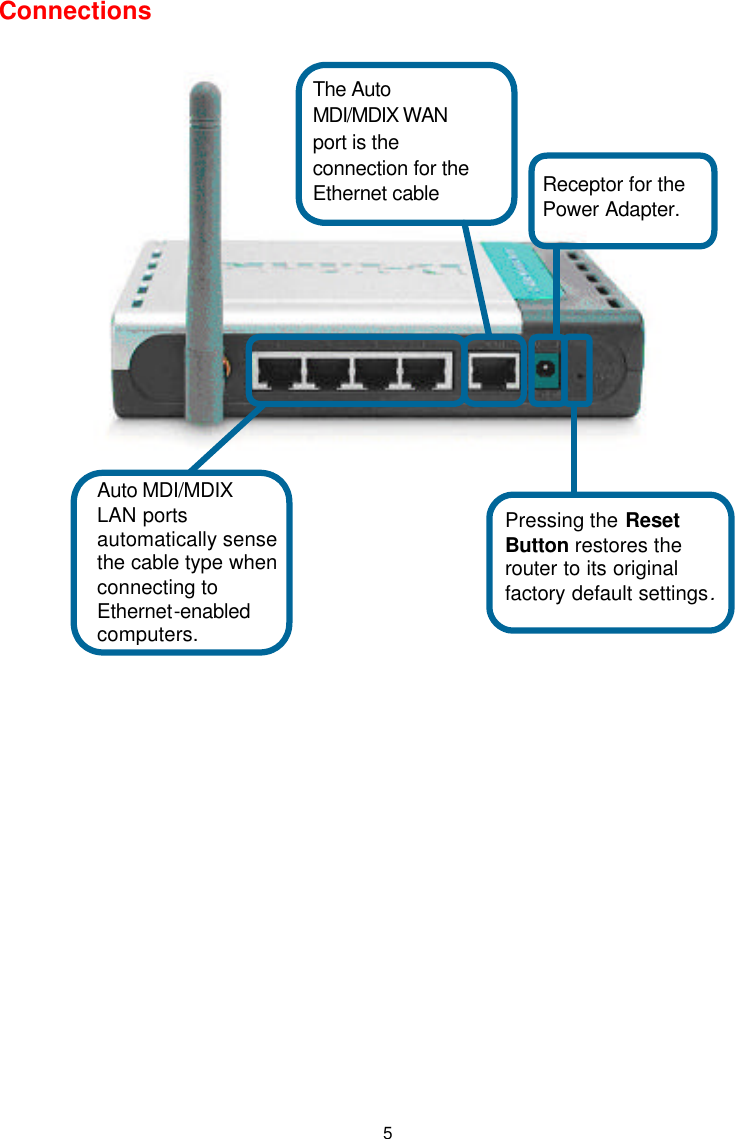
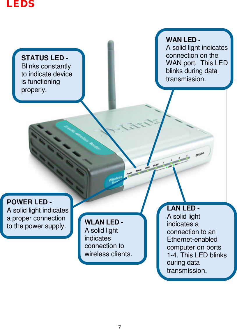
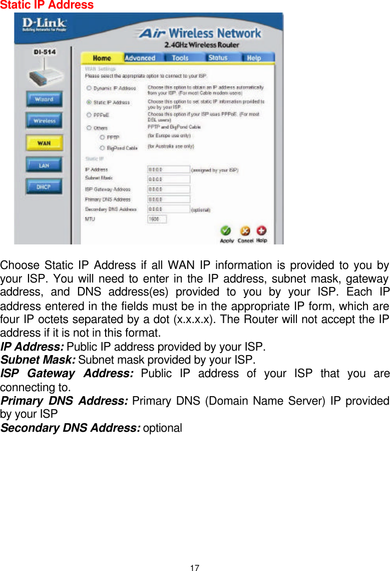
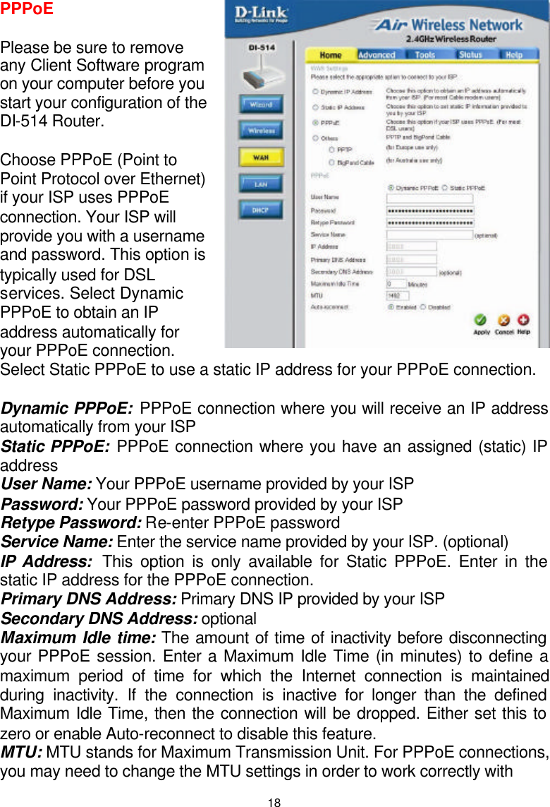
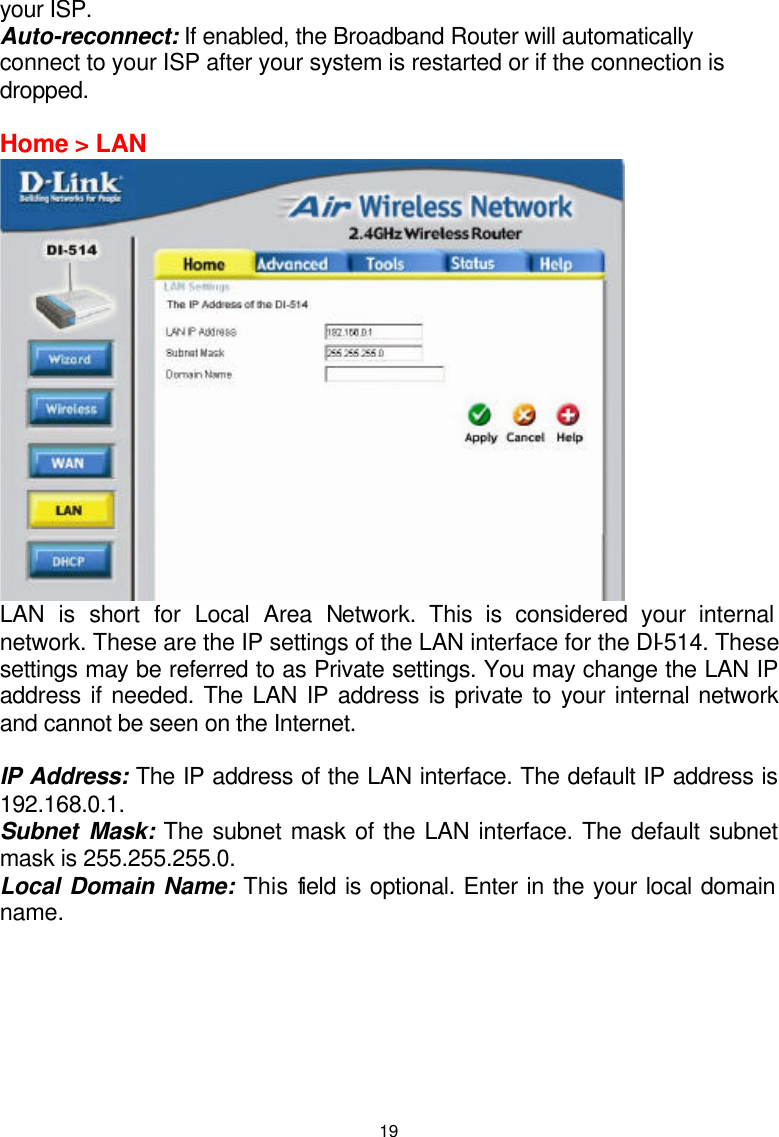
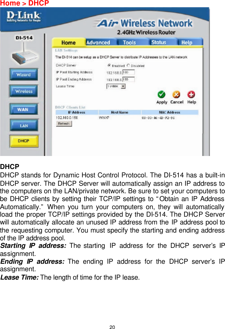
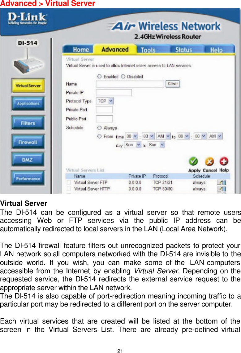
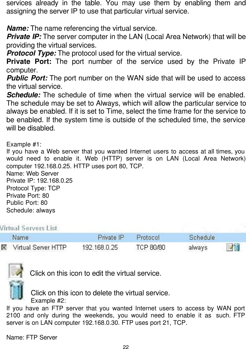
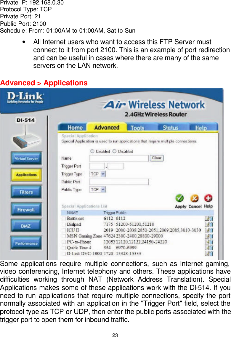
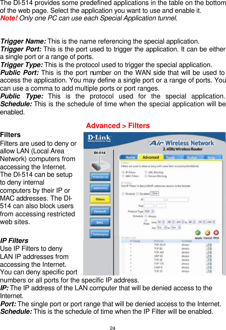
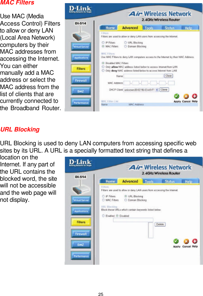
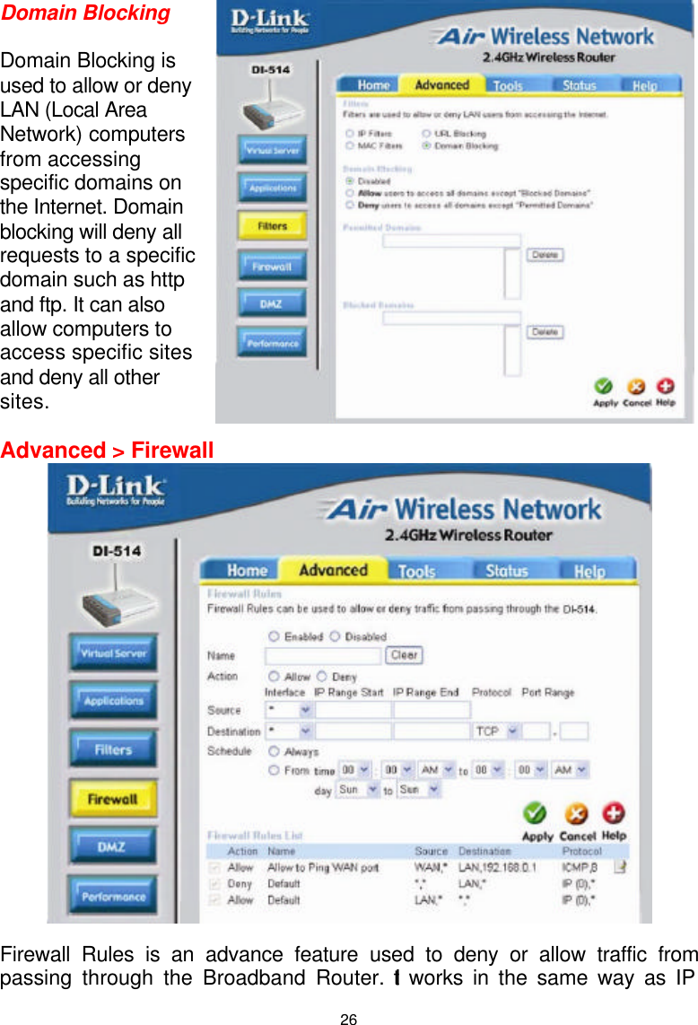
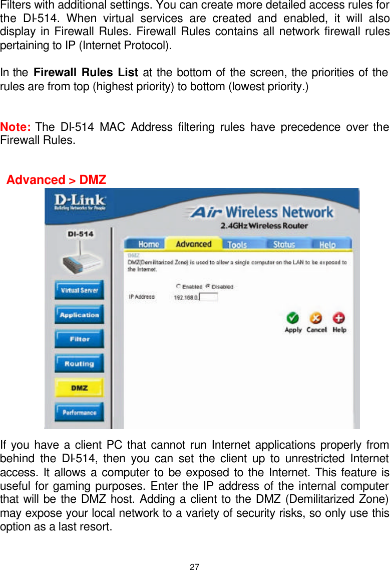
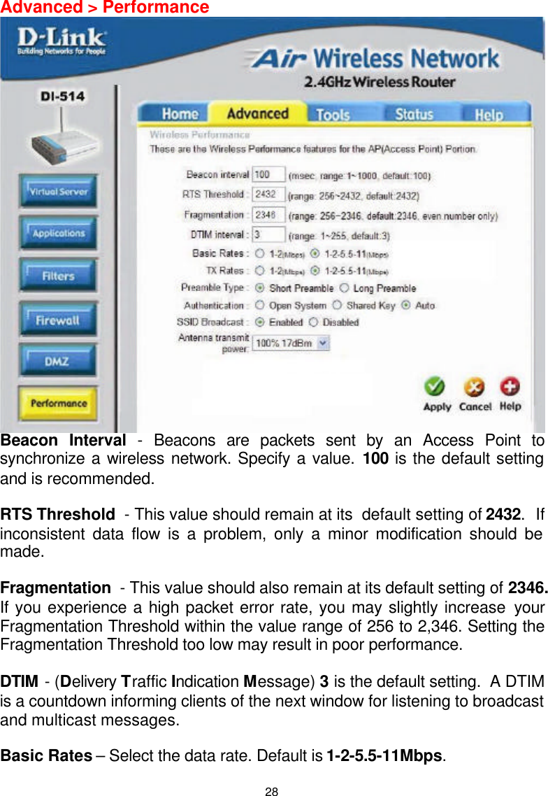
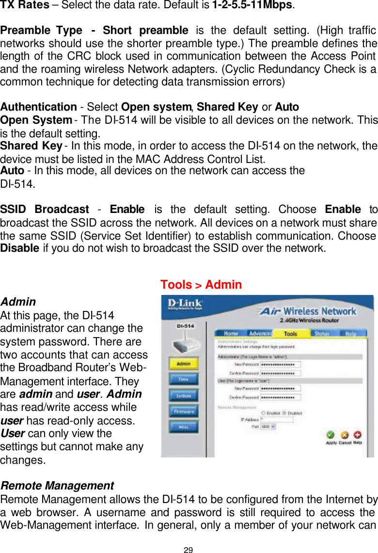
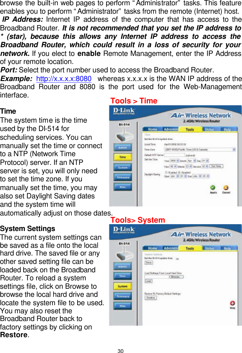
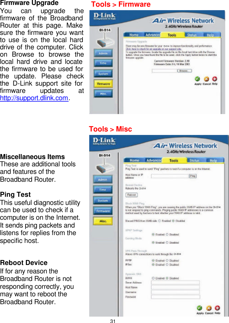
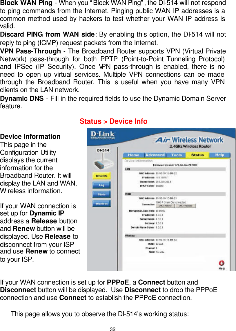
DI 514 User Manual
Users Manual
Navigation menu
Upload a User Manual
Namespaces
Wiki Guide
HTML
PDF
Info
Views
User Manual
Discussion / Help
Navigation