D Link DI-754 Multimode 5GHz Wireless Router User Manual di754 MANUAL 102
D Link Corporation Multimode 5GHz Wireless Router di754 MANUAL 102
D Link >
Contents
- 1. Manual 1 revised
- 2. Manual 3 revised
- 3. Correction to page 82 of manual
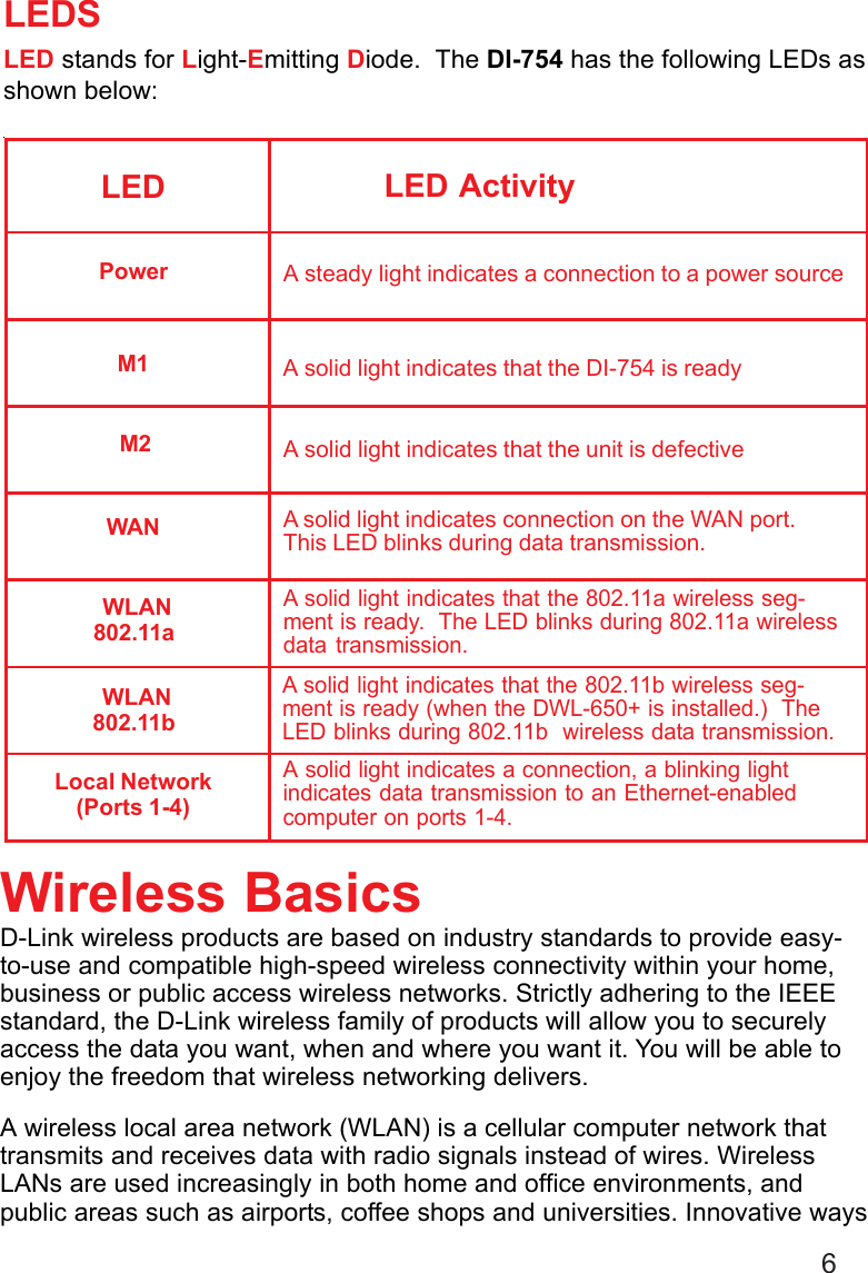
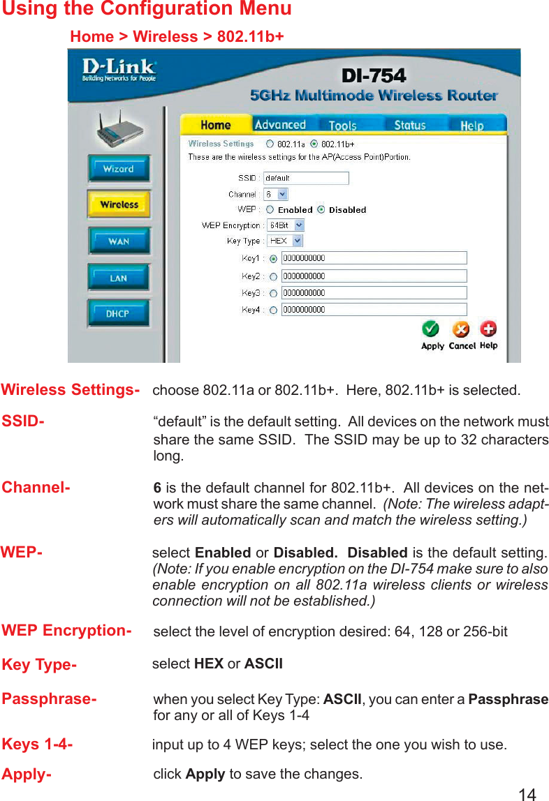
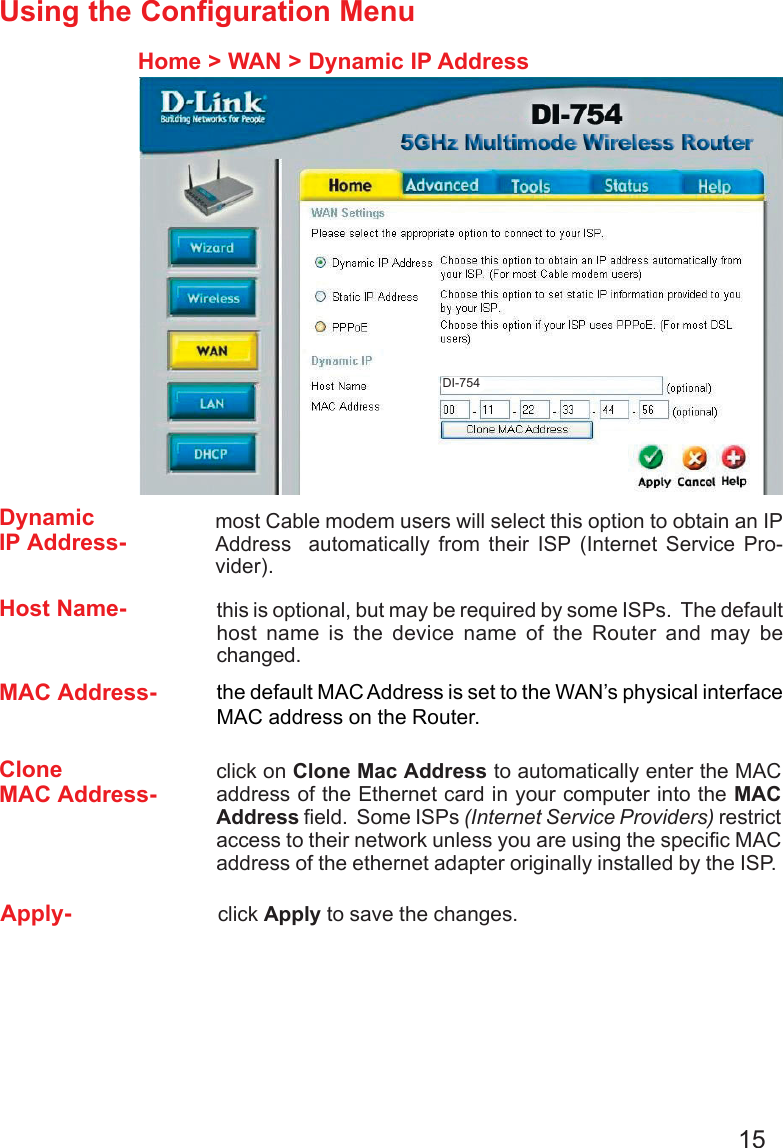
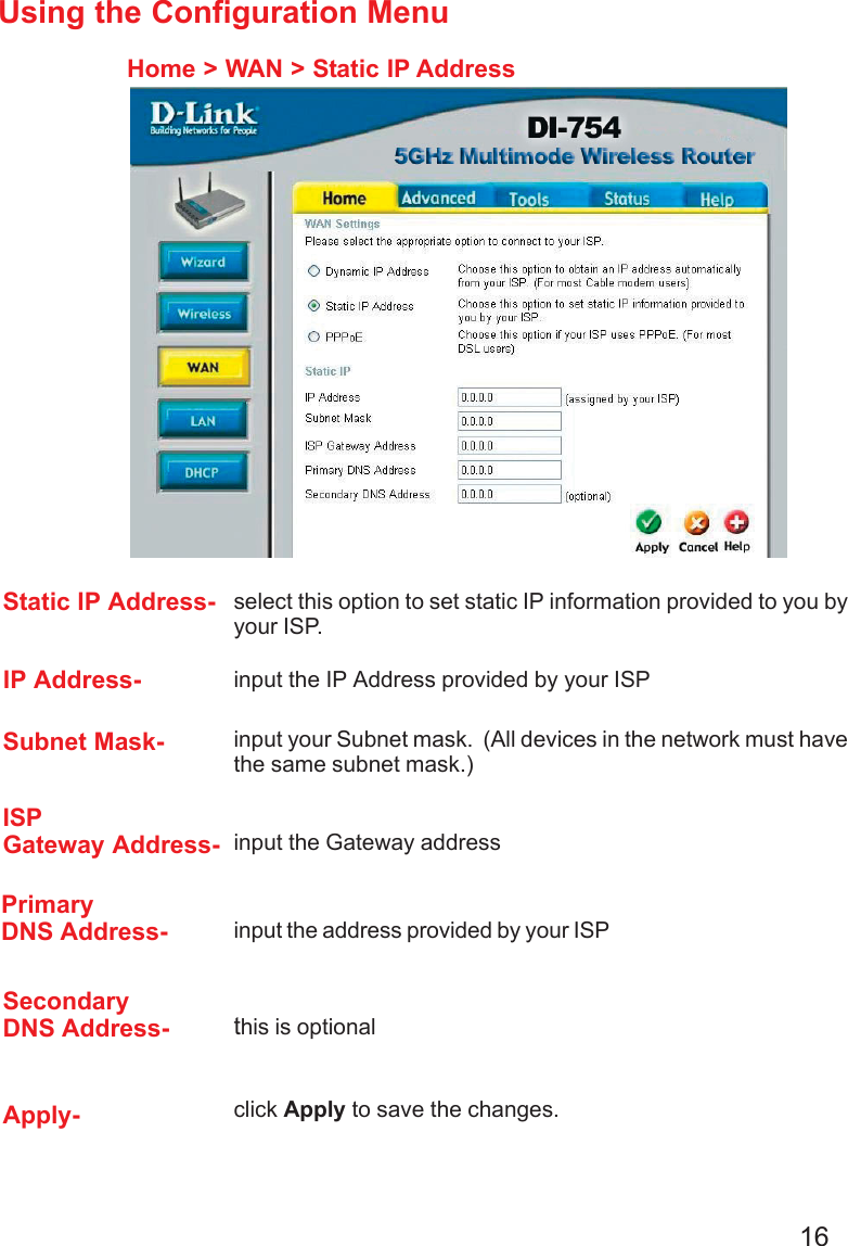
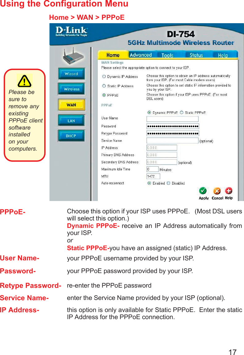
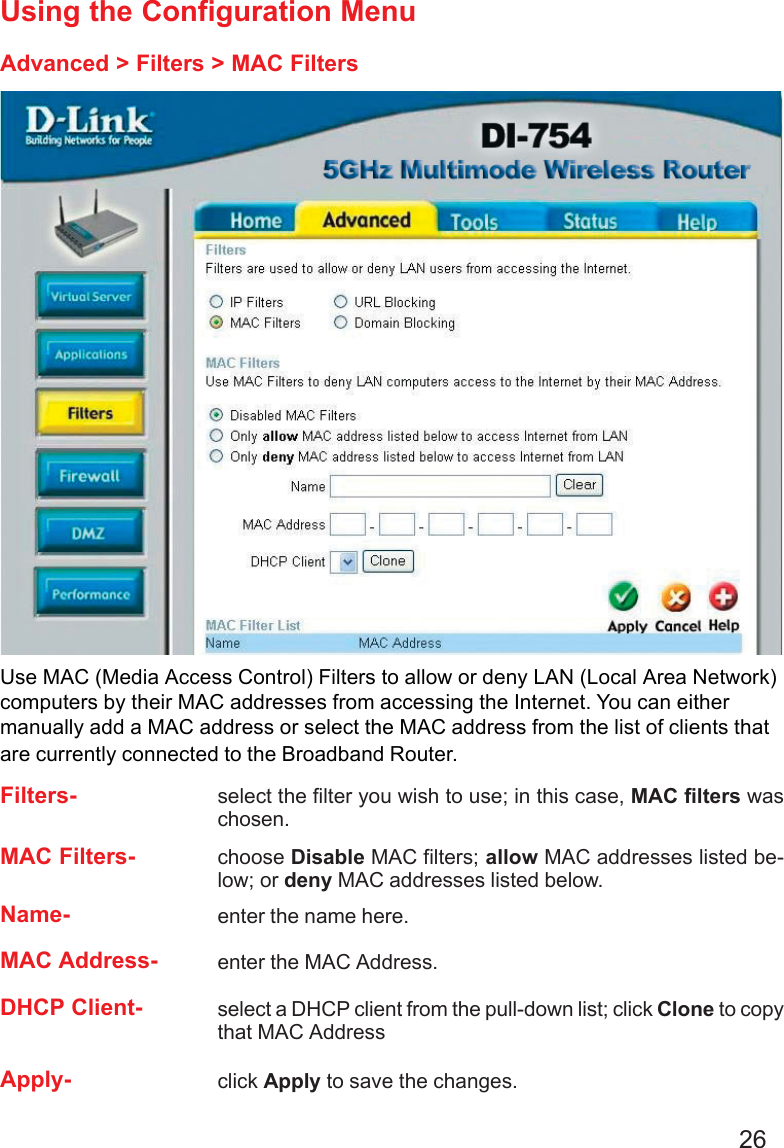
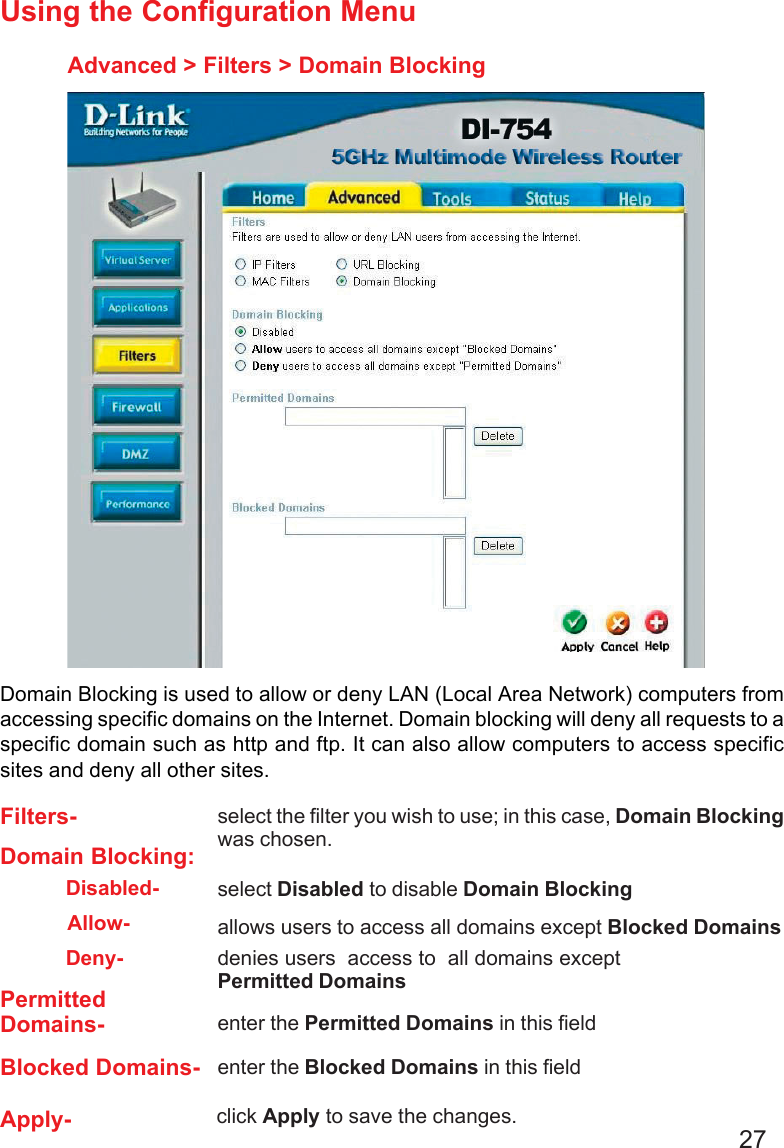
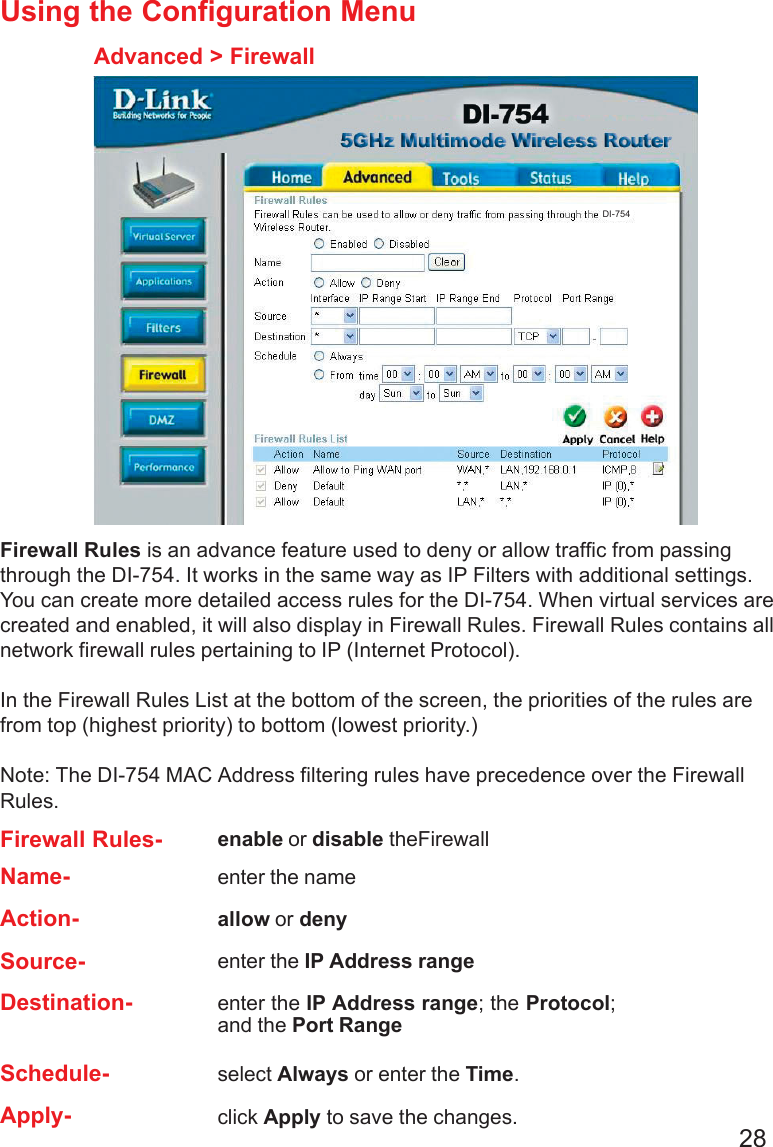
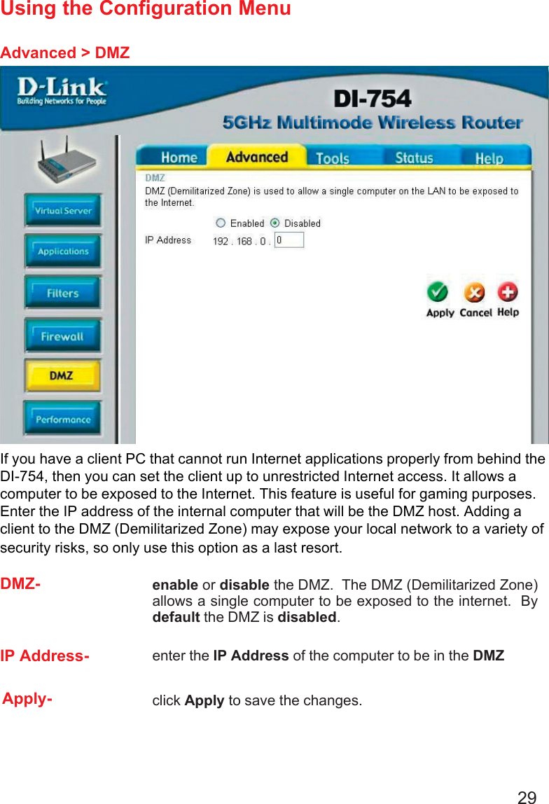
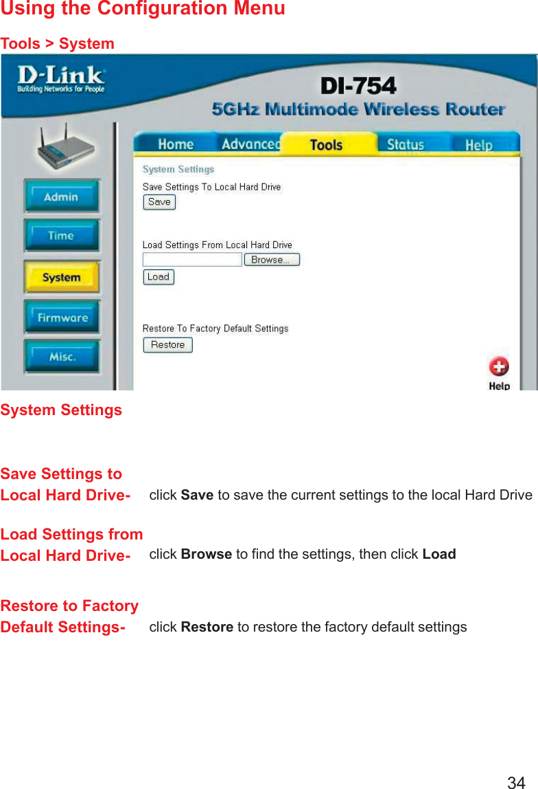
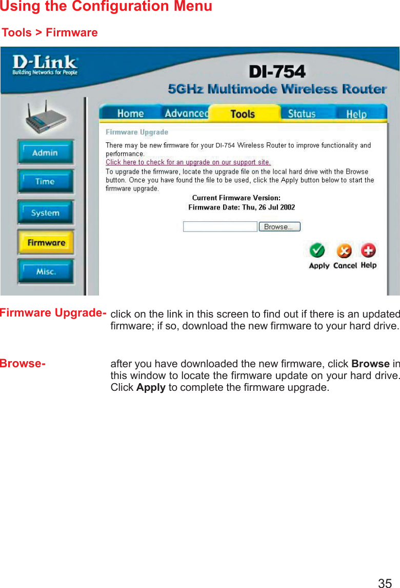
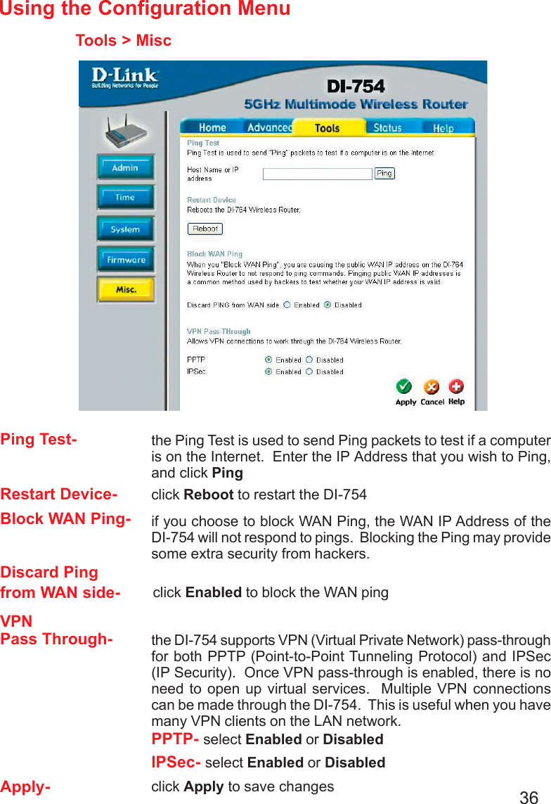
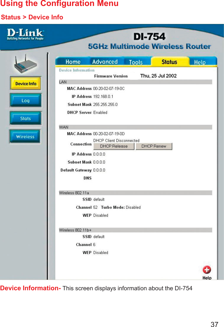
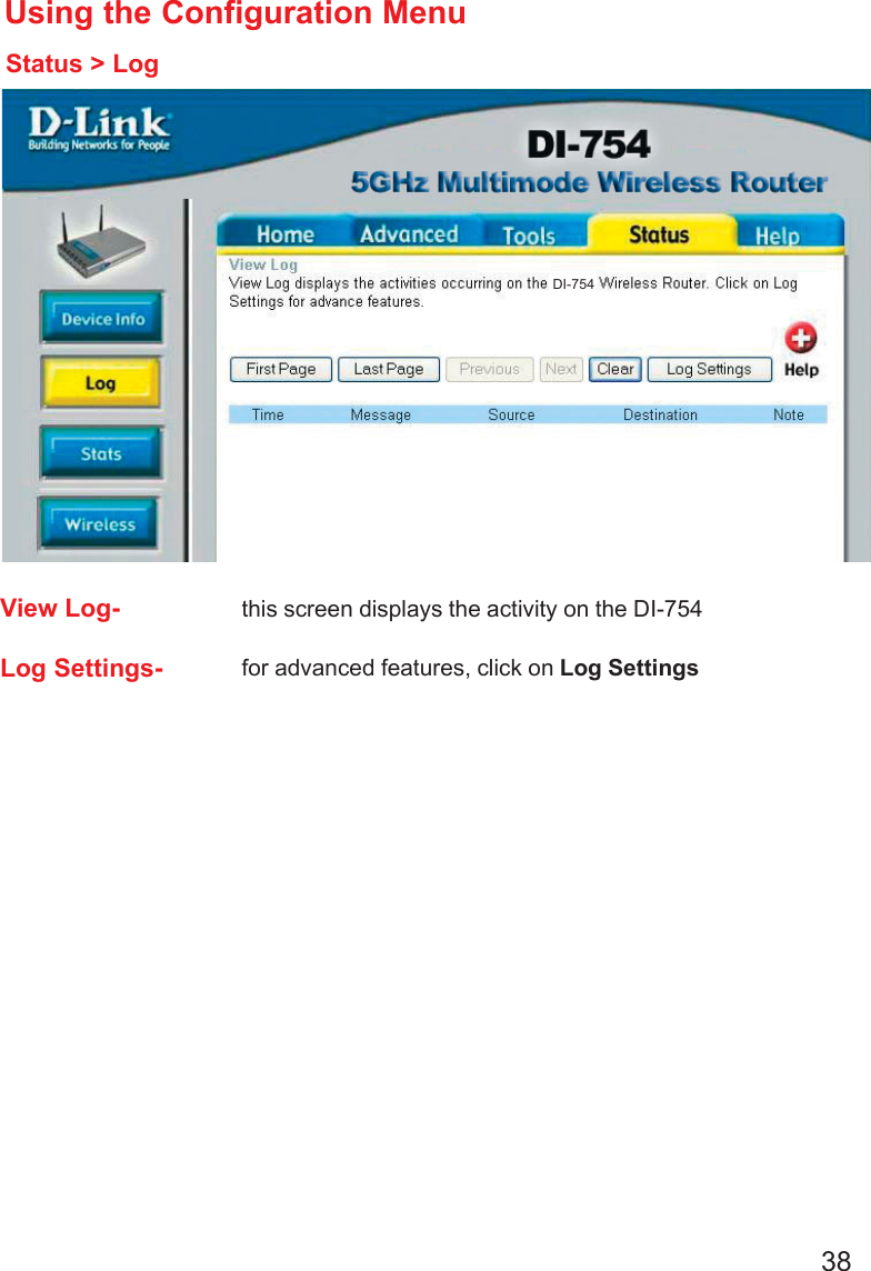
Manual 1 revised