D Link DI524C1 802.11 b/g WLAN Router User Manual DI 624 071003
D Link Corporation 802.11 b/g WLAN Router DI 624 071003
D Link >
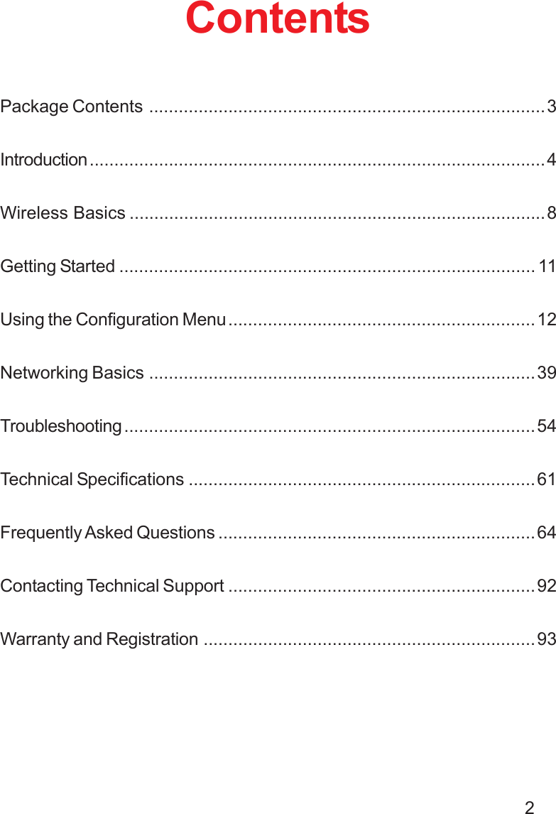
Contents
- 1. User manual part 1 of 3
- 2. User manual part 2 of 3
- 3. User manual part 3 of 3
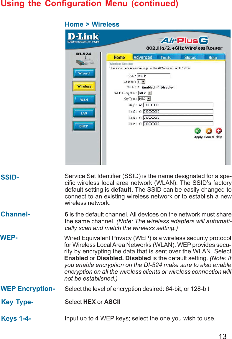
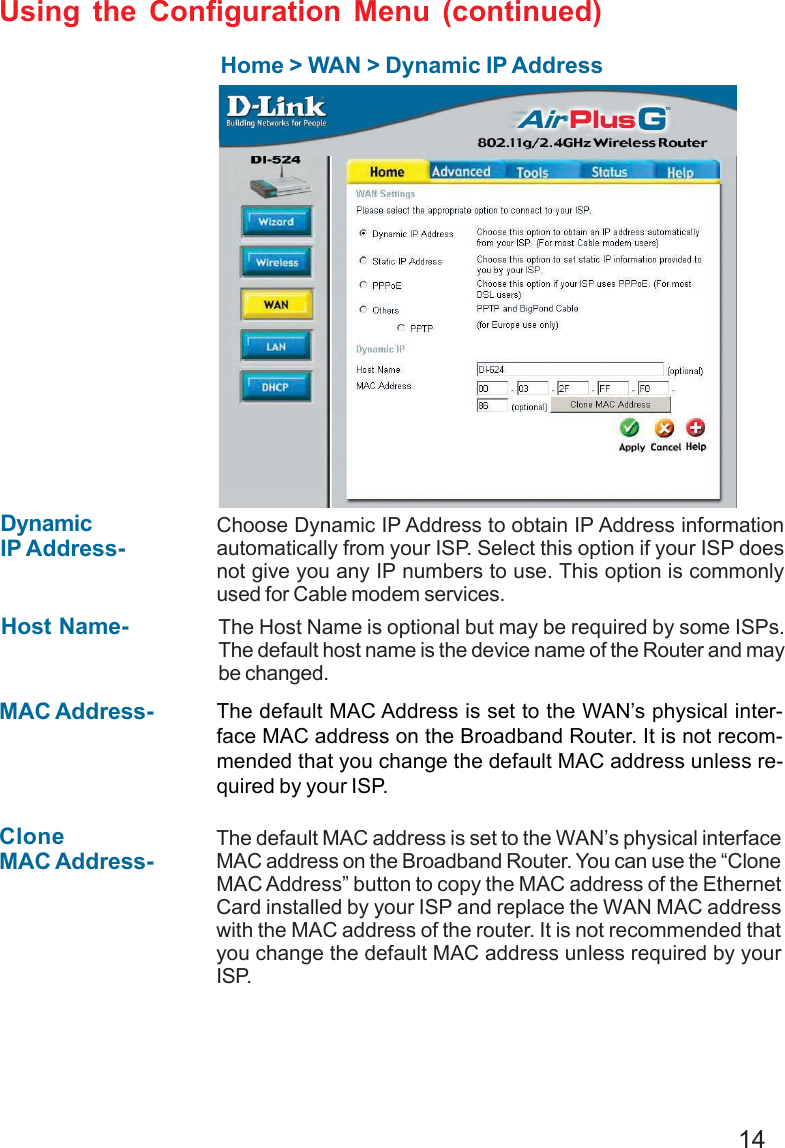
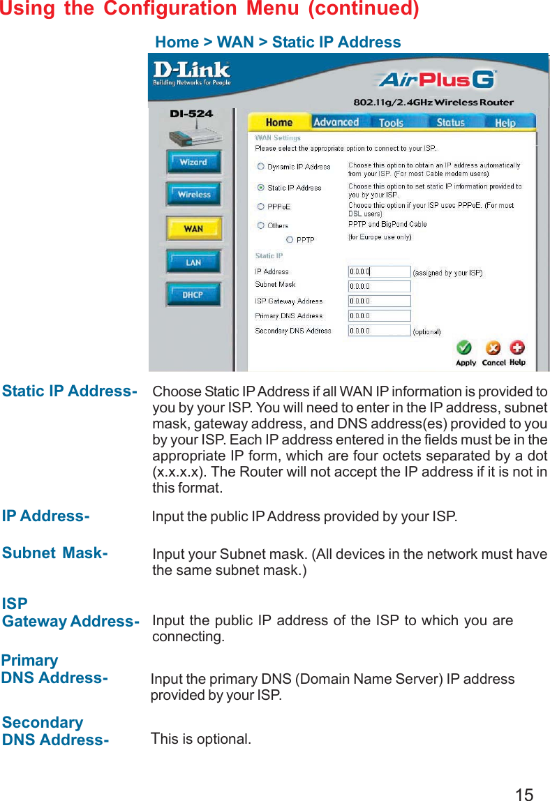
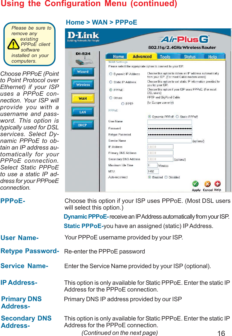
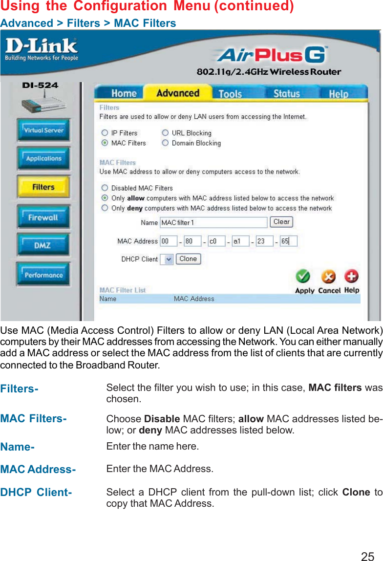
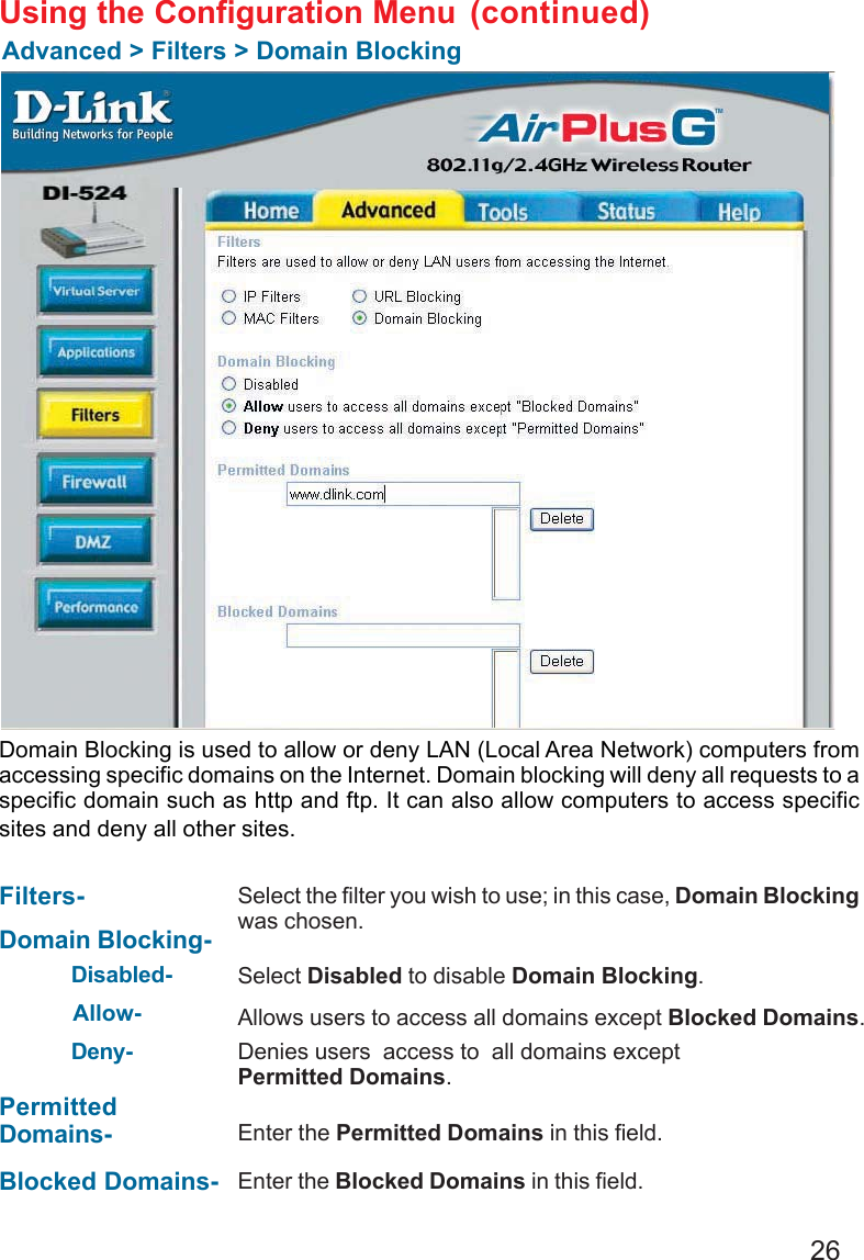
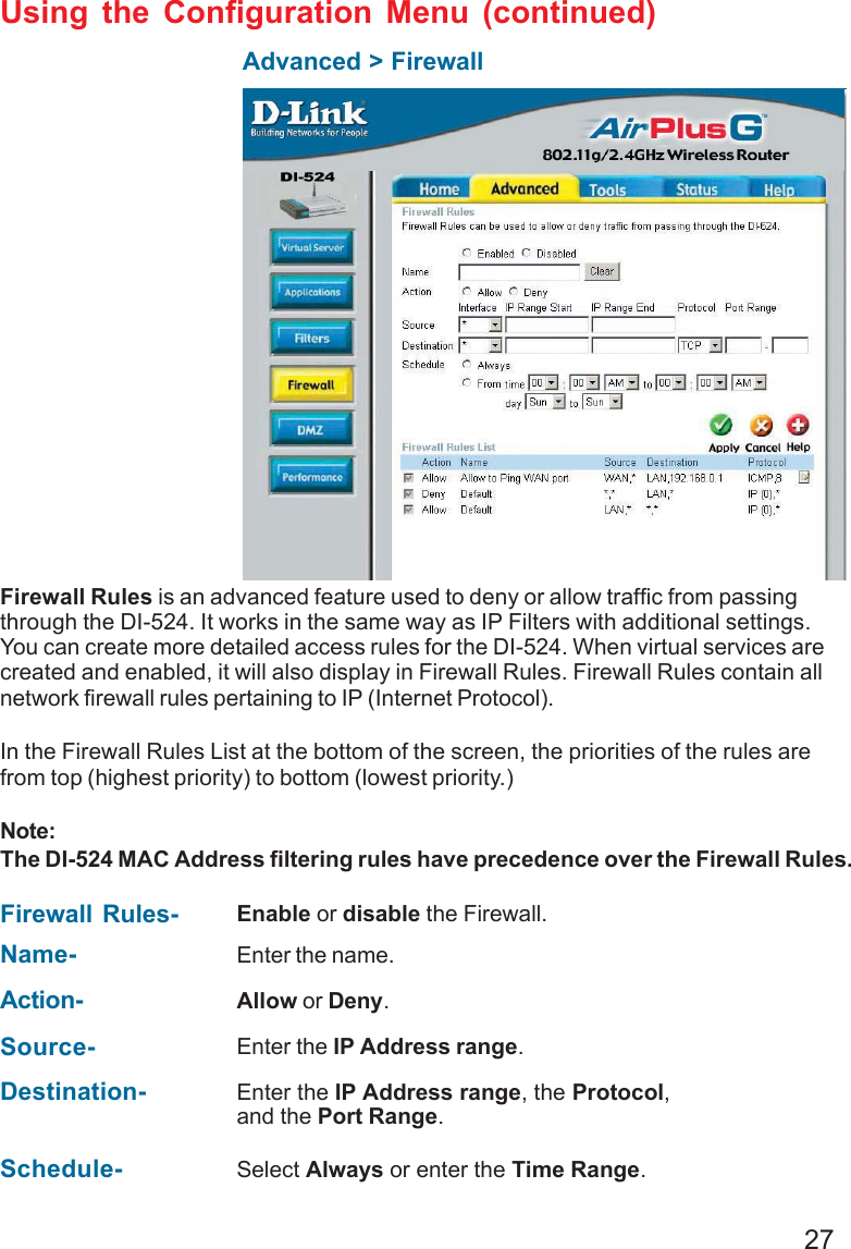
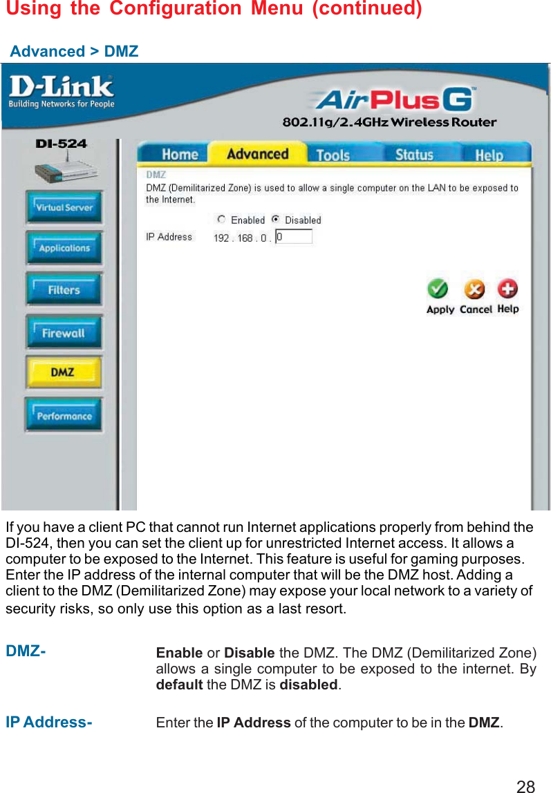
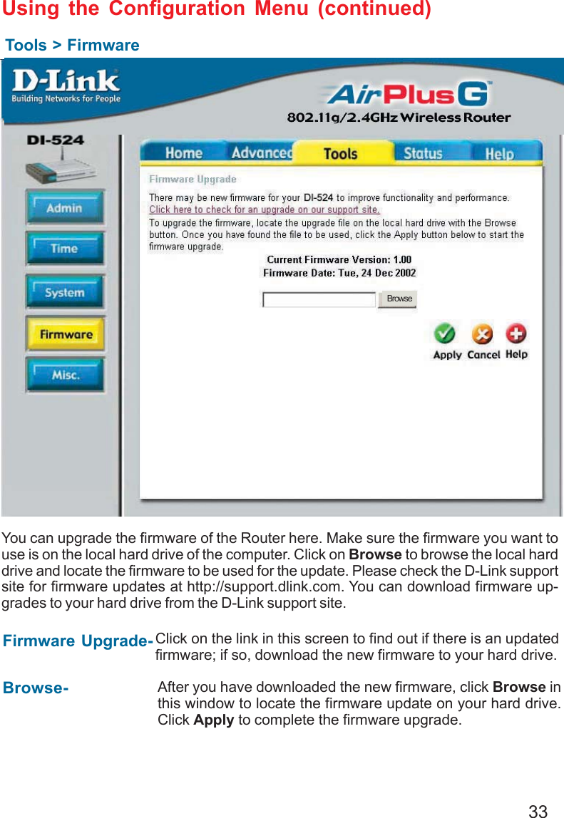
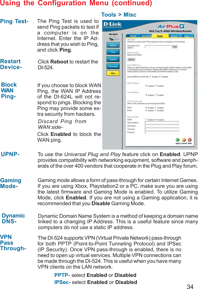
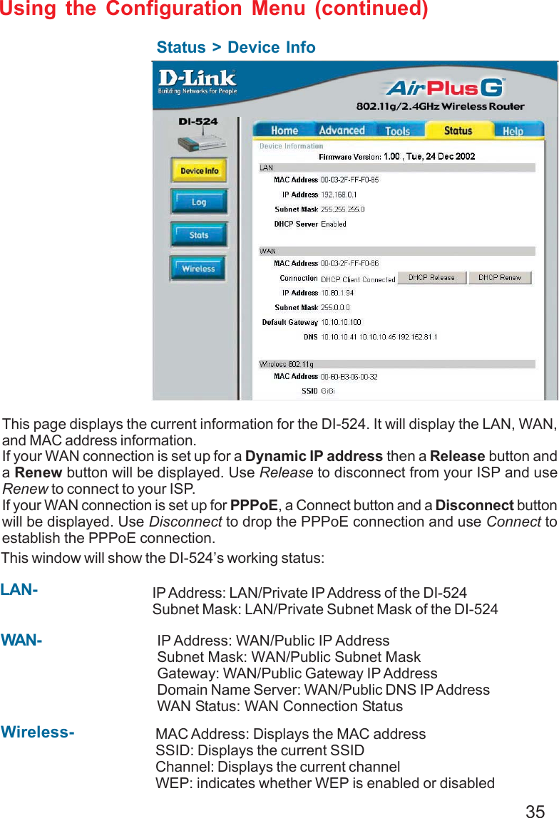
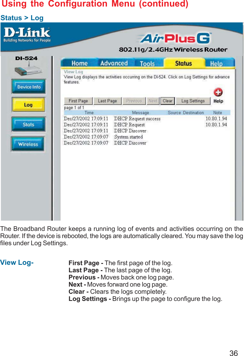
User manual part 1 of 3