D Link DI524UP WIRELESS BROADBAND ROUTER User Manual DI 524UP manual indd
D Link Corporation WIRELESS BROADBAND ROUTER DI 524UP manual indd
D Link >
Contents
- 1. users manual 1 of 2
- 2. users manual 2 of 2
users manual 2 of 2
50
Networking Basics
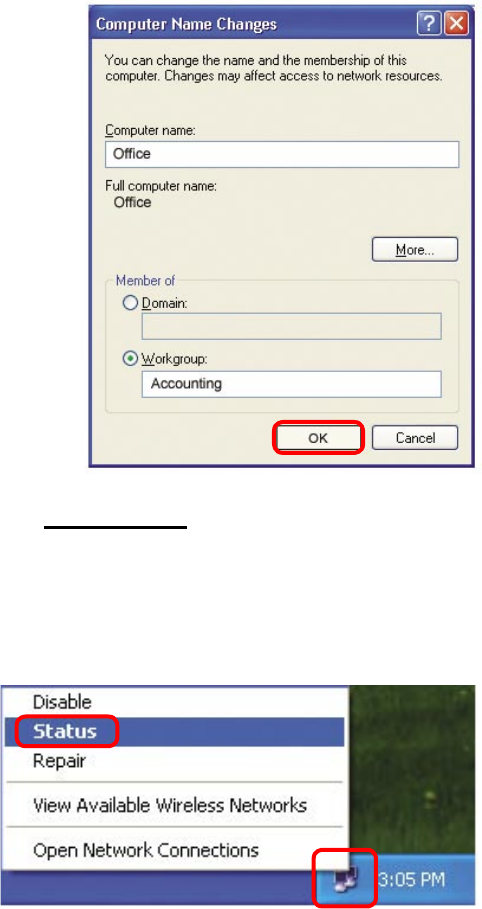
Naming your Computer
In this window, enter the
Computer name
Select Workgroup and enter
the name of the Workgroup
All computers on your
network must have the same
Workgroup name.
Click OK
Checking the IP Address in Windows XP
The wireless adapter-equipped computers in your network must be in the same IP Ad-
dress range (see Getting Started in this manual for a definition of IP Address Range.)
To check on the IP Address of the adapter, please do the following:
Right-click on
the Local Area
Connection icon
in the task bar
Click on Status
51
Networking Basics
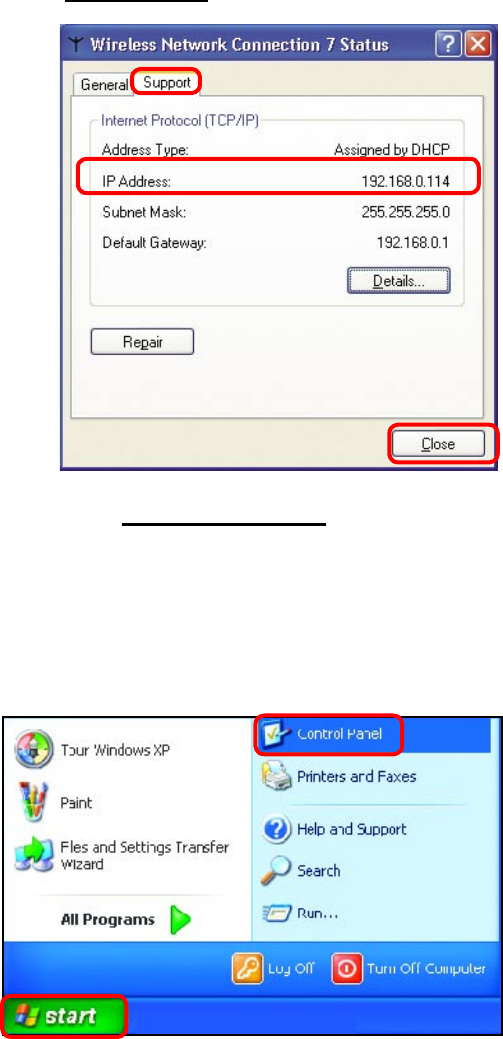
Checking the IP Address in Windows XP
This window will appear.
Click the
Support tab
Click Close
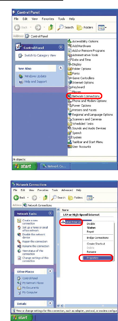
Assigning a Static IP Address in Windows XP/2000
Note: Residential Gateways/Broadband Routers will automatically assign IP Addresses
to the computers on the network, using DHCP (Dynamic Host Configuration Protocol)
technology. If you are using a DHCP-capable Gateway/Router you will not need to
assign Static IP Addresses.
If you are not using a DHCP capable Gateway/Router, or you need to assign a Static
IP Address, please follow these instructions:
Go to Start
Double-click on
Control Panel
52
Networking Basics
Assigning a Static IP Address in Windows XP/2000
Double-click
on Network
Connections
Double-click on
Properties
Right-click on Local Area
Connections
53
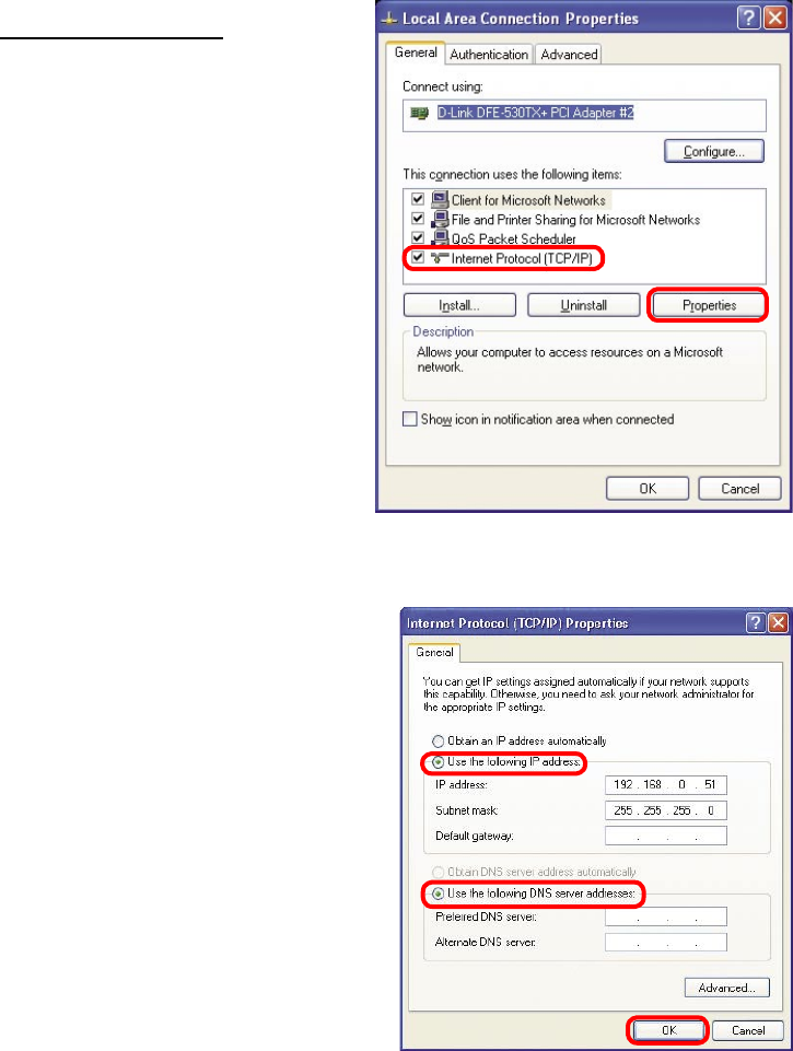
Input your IP address and
subnet mask. (The IP
Addresses on your network
must be within the same
range. For example, if
one computer has an IP
Address of 192.168.0.2,
the other computers should
have IP Addresses that are
sequential, like 192.168.0.3
and 192.168.0.4. The subnet
mask must be the same for
all the computers on the
network.)
Networking Basics
Assigning a Static IP Address
in Windows XP/2000
Input your DNS server
addresses. (Note: If you
are entering a DNS server,
you must enter the IP
Address of the Default
Gateway.)
The DNS server information will be supplied
by your ISP (Internet Service Provider.)
Click OK
Click on Internet Protocol
(TCP/IP)
Click Properties
54
Networking Basics
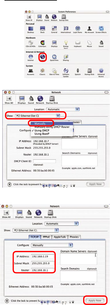
Assigning a Static IP Address with Macintosh OSX
Go to the Apple Menu and select
System Preferences
cClick on Network
Select Built-in Ethernet in the
Show pull-down menu
Select Manually in the
Configure pull-down menu
Input the Static IP Address,
the Subnet Mask and the
Router IP Address in the
appropriate fields
Click Apply Now
55
Networking Basics
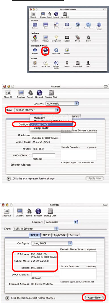
Selecting a Dynamic IP Address with Macintosh OSX
Go to the Apple Menu and select
System Preferences
Click on Network
Select Built-in Ethernet in the
Show pull-down menu
Select Using DHCP in the
Configure pull-down menu
Click Apply Now
The IP Address, Subnet
mask, and the Router’s IP
Address will appear in a few
seconds
56
Networking Basics
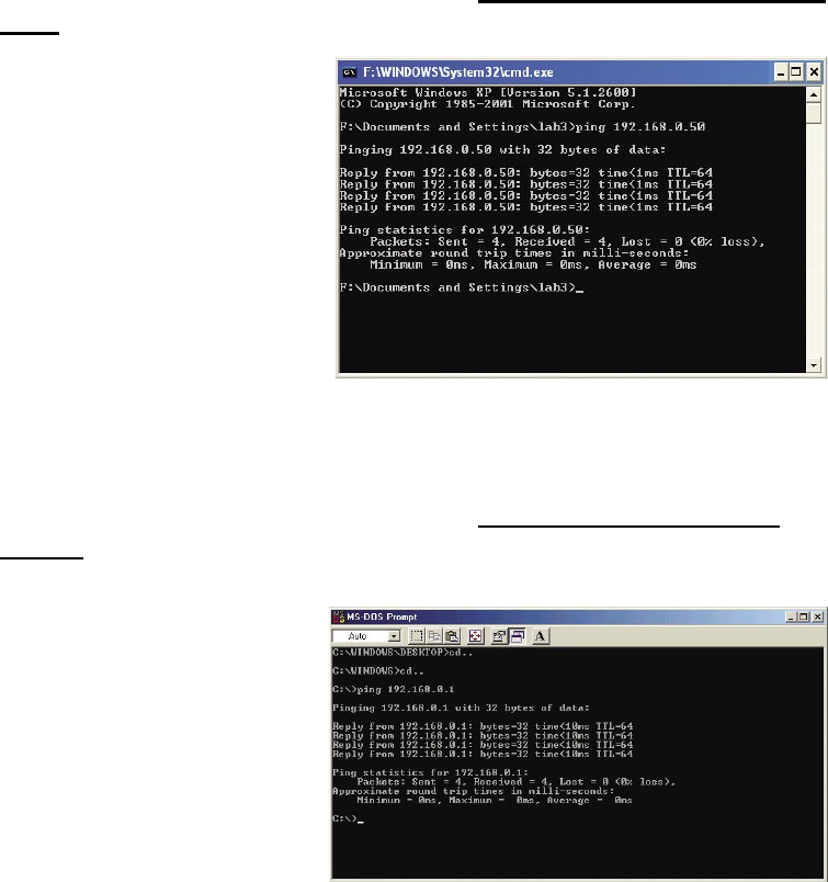
Checking the Wireless Connection by Pinging in Windows XP and
2000
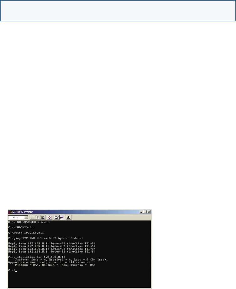
Checking the Wireless Connection by Pinging in Windows Me
and 98
Go to Start > Run >
type cmd. A window
similar to this one
will appear. Type
ping xxx.xxx.xxx.
xxx, where xxx is
the IP Address of
the Wireless Router
or Access Point.
A good wireless
connection will show
four replies from
the Wireless Router
or Acess Point, as
shown.
Go to Start > Run
> type command.
A window similar
to this will appear.
Type ping xxx.xxx.
xxx.xxx where xxx
is the IP Address
of the Wireless
Router or Access
Point. A good
wireless connection
will show four
replies from the
wireless router or
access point, as
shown.
57
Troubleshooting
This Chapter provides solutions to problems that can occur during the installation and
operation of the DI-524UP Wireless Broadband Router. We cover various aspects of
the network setup, including the network adapters. Please read the following if you are
having problems.
Note: If you have
changed the default IP
Address, make sure to
ping the correct IP Ad-
dress assigned to the
DI-524UP.
Note: It is recommended that you use an Ethernet connection to
configure the DI-524UP Wireless Broadband Router.
1. The computer used to configure the DI-524UP cannot access
the
Configuration menu.
Check that the Ethernet LED on the DI-524UP is ON. If the LED is
not ON, check that the cable for the Ethernet connection is securely
inserted.
Check that the Ethernet Adapter is working properly. Please see
item 3 (Check that the drivers for the network adapters are
installed properly) in this Troubleshooting section to check that
the drivers are loaded properly.
Check that the IP Address is in the same range and subnet as the
DI-524UP. Please see Checking the IP Address in Windows XP
in the Networking Basics section of this manual.
Note: The IP Address of the DI-524UP is 192.168.0.1. All the computers on the
network must have a unique IP Address in the same range, e.g., 192.168.0.x.
Any computers that have identical IP Addresses will not be visible on the
network. They must all have the same subnet mask, e.g., 255.255.255.0
Do a Ping test to make sure that the DI-524UP is responding. Go to
Start>Run>Type Command>Type ping 192.168.0.1. A successful
ping will show four replies.
58
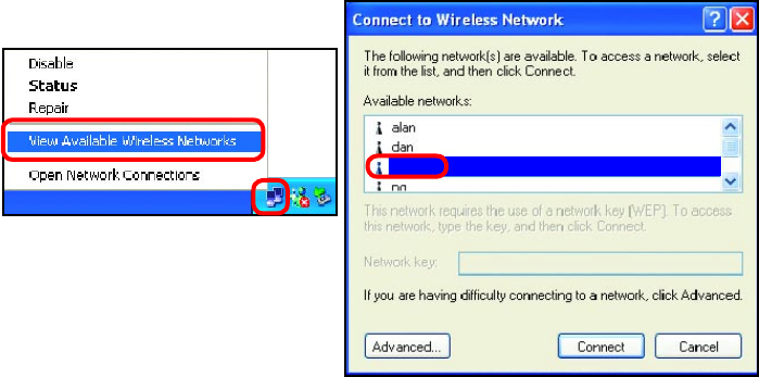
2. The wireless client cannot access the Internet in the
Infrastructure mode.
Make sure the wireless client is associated and joined with the correct Access
Point. To check this connection: Right-click on the Local Area Connection
icon in the taskbar> select View Available Wireless Networks. The Connect to
Wireless Network screen will appear. Please make sure you have selected the
correct available network, as shown in the illustrations below.
Troubleshooting
Check that the IP Address assigned to the wireless adapter is within
the same IP Address range as the access point and gateway. (Since
the DI-524UP has an IP Address of 192.168.0.1, wireless adapters must
have an IP Address in the same range, e.g., 192.168.0.x. Each device
must have a unique IP Address; no two devices may have the same IP
Address. The subnet mask must be the same for all the computers on
the network.) To check the IP Address assigned to the wireless adapter,
double-click on the Local Area Connection icon in the taskbar >
select the Support tab and the IP Address will be displayed. (Please
refer to Checking the IP Address in the Networking Basics section of
this manual.)
If it is necessary to assign a Static IP Address to the wireless adapter,
please refer to the appropriate section in Networking Basics. If you
are entering a DNS Server address you must also enter the Default
Gateway Address. (Remember that if you have a DHCP-capable router,
you will not need to assign a Static IP Address. See Networking
Basics: Assigning a Static IP Address.)
59
Troubleshooting
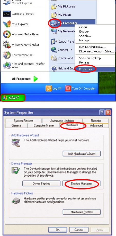
3. Check that the drivers for the network adapters are
installed properly.
You may be using different network adapters than those illustrated here, but this
procedure will remain the same, regardless of the type of network adapters you are
using.
Click Device
Manager
Select the
Hardware
Tab
Go to Start >
My Computer >
Properties
60
Troubleshooting
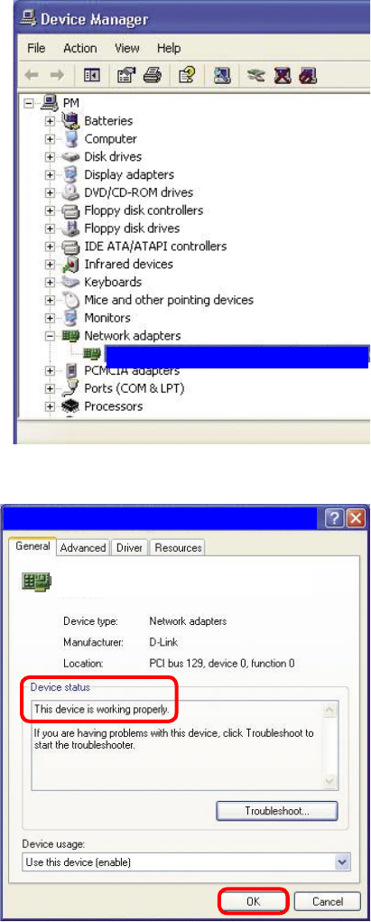
Double-click
on Network
Adapters
Right-click on D-Link
AirPlus DWL-G650
Wireless Cardbus
Adapter (In this example
we use the DWL-G650;
you may be using other
network adapters, but
the procedure will remain
the same.)
Select Properties
to check that
the drivers are
installed properly
Look under Device
Status to check that the
device is working
properly
Click OK
D-Link AirPlus DWL-G650 Wireless Cardbus Adapter
D-Link AirPlus DWL-G650 Wireless Cardbus Adapter
D-Link AirPlus DWL-G650
61
Troubleshooting
4. What variables may cause my wireless products
to lose reception?
D-Link products let you access your network from virtually anywhere you want. However,
the positioning of the products within your environment will affect the wireless range.
Please refer to Installation Considerations in the Wireless Basics section of this
manual for further information about the most advantageous placement of your D-Link
wireless products.
5. Why does my wireless connection keep dropping?
6. Why can’t I get a wireless connection?
If you have enabled Encryption on the DI-524UP, you must also enable encryption on
all wireless clients in order to establish a wireless connection.
Make sure that the SSID on the Router and the Wireless Client are exactly the
same. If they are not, wireless connection will not be established.
For 802.11b, the Encryption settings are: 64, 128, or 256 bit. Make sure that
the encryption bit level is the same on the Router and the Wireless Client.
Move the DI-524UP and the wireless client into the same room and then test
the wireless connection.
Disable all security settings. (WEP, MAC Address Control)
Antenna Orientation- Try different antenna orientations for the DI-524UP. Try
to keep the antenna at least 6 inches away from the wall or other objects.
If you are using 2.4GHz cordless phones, X-10 equipment or other home
security systems, ceiling fans, and lights, your wireless connection will degrade
dramatically or drop altogether. Try changing the Channel on your Router, Access
Point and Wireless adapter to a different Channel to avoid interference.
Keep your product away (at least 3-6 feet) from electrical devices that generate
RF noise, like microwaves, Monitors, electric motors, etc.
62
Troubleshooting
6. Why can’t I get a wireless connection? (continued)
Turn off your DI-524UP and the client. Turn the DI-524UP back on again, and
then turn on the client.
Check that the LED indicators are indicating normal activity. If not, check that
the AC power and Ethernet cables are firmly connected.
Make sure that all devices are set to Infrastructure mode.
Check that the IP Address, subnet mask, gateway and DNS settings are cor-
rectly entered for the network.
If you are using 2.4GHz cordless phones, X-10 equipment or other home se-
curity systems, ceiling fans, and lights, your wireless connection will degrade
dramatically or drop altogether. Try changing the Channel on your DI-524UP,
and on all the devices in your network to avoid interference.
Keep your product away (at least 3-6 feet) from electrical devices that generate
RF noise, like microwaves, Monitors, electric motors, etc.
7. I forgot my encryption key.
Reset the DI-524UP to its factory default settings and restore the other devices
on your network to their default settings. You may do this by pressing the Reset
button on the back of the unit. You will lose the current configuration settings.
63
8. Resetting the DI-524UP to Factory Default Settings
After you have tried other methods for troubleshooting your network, you may
choose to Reset the DI-524UP to the factory default settings. Remember that
D-Link AirPro products network together, out of the box, at the factory default
settings.
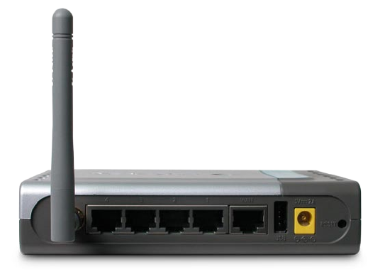
To hard-reset the DI-524UP to Factory Default Settings, please do the following:
Troubleshooting
After the DI-524UP reboots (this may take a few min-
utes) it will be reset to the factory Default settings
Use a paper clip to press the Reset button
Hold for about 10 seconds and then release
Locate the Reset button on the back of the DI-524UP
64
IP Filtering
URL Filtering
Domain Blocking
Scheduling
IEEE 802.11b
IEEE 802.3
IEEE 802.3u
Technical Specifications
L2TP
Standards
VPN Pass Through/ Multi-Sessions
PPTP
Device Management
Web-Based- Internet Explorer v6 or later; Netscape Navigator v7
or later; or other Java-enabled browsers
Advanced Firewall Features
NAT with VPN Passthrough (Network Address Translation)
95% maximum (non-condensing)
Operating Temperature
32ºF to 131ºF (0ºC to 55ºC)
Humidity:
Indoors – up to 328 feet (100 meters)
IPSec
DHCP Server and Client
MAC Filtering
Outdoors – up to 984 feet (300 meters)
Safety and Emissions:
FCC, CE
IEEE 802.11g
2.4GHz to 2.462GHz
Wireless Frequency Range:
Reset
65
LEDs:
Power
WAN
Physical Dimensions:
Technical Specifications
L = 5.6 inches (142mm)
W = 4.3 inches (109mm)
H = 1.2 inches (31mm)
Wireless Transmit Power:
14dBm
Security:
802.1x
WEP
WPA
WPA-PSK
External Antenna Type:
Single detachable reverse SMA
Orthogonal Frequency Division Multiplexing (OFDM)
Modulation Technology:
Power Input:
Ext. Power Supply DC 5V, 2A
Weight:
0.44 lbs. (200g)
LAN (10/100)
WLAN (Wireless Connection)
Warranty:
1 year
Wireless Operating Range
66
54 Mbps
48 Mbps
36 Mbps
24 Mbps
18 Mbps
12 Mbps
11 Mbps
9 Mbps
6 Mbps
5.5 Mbps
2 Mbps
1 Mbps
Wireless Data Rates with Automatic Fallback:
54Mbps OFDM, 10% PER, -68dBm
48Mbps OFDM, 10% PER, -68dBm
36Mbps OFDM, 10% PER, -75dBm
Receiver Sensitivity:
24Mbps OFDM, 10% PER, -79dBm
18Mbps OFDM, 10% PER, -82dBm
12Mbps OFDM, 10% PER, -84dBm
11Mbps CCK, 8% PER, -82dBm
9Mbps OFDM, 10% PER, -87dBm
6Mbps OFDM, 10% PER, -88dBm
5.5Mbps CCK, 8% PER, -85dBm
2Mbps QPSK, 8% PER, -86dBm
1Mbps BPSK, 8% PER, -89dBm
Technical Specifications
67
Frequently Asked Questions
When entering the IP Address of the DI-524UP (192.168.0.1), you are not
connecting to the Internet or have to be connected to the Internet. The device has
the utility built-in to a ROM chip in the device itself. Your computer must be on the
same IP subnet to connect to the web-based utility.
To resolve difficulties accessing a web utility, please follow the steps below.
Step 1 Verify physical connectivity by checking for solid link lights on the device.
If you do not get a solid link light, try using a different cable or connect to a different
port on the device if possible. If the computer is turned off, the link light may not be
on.
The following connections require a Crossover Cable:
Computer to Computer
Computer to Uplink Port
Computer to Access Point
Computer to Print Server
Computer/XBOX/PS2 to DWL-810
Computer/XBOX/PS2 to DWL-900AP+
Uplink Port to Uplink Port (hub/switch)
Normal Port to Normal Port (hub/switch)
The following connections require a Straight-through Cable:
Computer to Residential Gateway/Router
Computer to Normal Port (hub/switch)
Access Point to Normal Port (hub/switch)
Print Server to Normal Port (hub/switch)
Uplink Port to Normal Port (hub/switch)
Rule of Thumb:
”If there is a link light, the cable is right.”
What type of cable should I be using?
Why can´t I access the web based configuration?
68
Frequently Asked Questions (continued)
What type of cable should I be using? (continued)
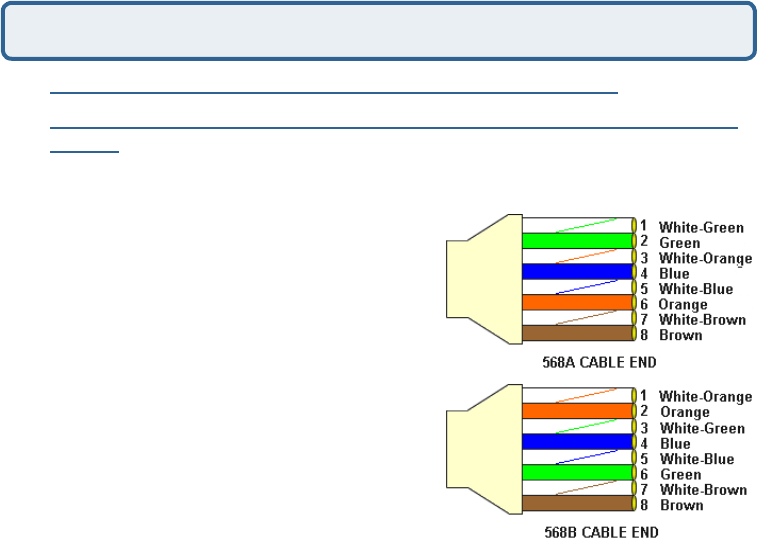
What´s the difference between a crossover cable and a straight-through
cable?
The wiring in crossover and straight-through cables are different. The two
types of cable have different purposes
for different LAN configurations. EIA/TIA
568A/568B define the wiring standards
and allow for two different wiring color
codes as illustrated in the following
diagram.
*The wires with colored backgrounds may
have white stripes and may be denoted
that way in diagrams found elsewhere.
How to tell straight-through cable from
a crossover cable:
The main way to tell the difference
between the two cable types is to
compare the wiring order on the ends
of the cable. If the wiring is the same on
both sides, it is straight-through cable. If one side has opposite wiring, it is a
crossover cable.
All you need to remember to properly configure the cables is the pinout order of
the two cable ends and the following rules:
A straight-through cable has identical ends
A crossover cable has different ends
It makes no functional difference which standard you follow for straight-through
cable ends, as long as both ends are the same. You can start a crossover cable
with either standard as long as the other end is the other standard. It makes no
functional difference which end is which. The order in which you pin the cable
is important. Using a pattern other than what is specified in the above diagram
could cause connection problems.
When to use a crossover cable and when to use a straight-through cable:
Computer to Computer – Crossover
Computer to an normal port on a Hub/Switch – Straight-through
Computer to an uplink port on a Hub/Switch - Crossover
Hub/Switch uplink port to another Hub/Switch uplink port – Crossover
Hub/Switch uplink port to another Hub/Switch normal port - Straight-through
Why can´t I access the web based configuration? (continued)
69
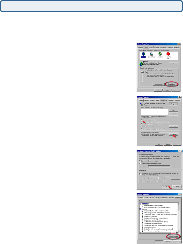
Step 3 Configure your Internet settings.
Step 2 Disable any Internet security software running on the computer. Software
firewalls like Zone Alarm, Black Ice, Sygate, Norton Personal Firewall, etc. might
block access to the configuration pages. Check the help files included with your
firewall software for more information on disabling or configuring it.
Frequently Asked Questions (continued)
Click to the Connection tab and set the dial-
up option to Never Dial a Connection. Click
the LAN Settings button
Nothing should be checked. Click OK
Go to the Advanced tab and click the
button to restore these settings to their
defaults
Click OK. Go to the desktop and close any open
windows
Go to Start>Settings>Control Panel. Double
click the Internet Options Icon. From the Security
tab, click the button to restore the settings to their
defaults.
Why can´t I access the web based configuration? (continued)
70
Frequently Asked Questions (continued)
Step 4 Check your IP Address. Your computer must have an IP Address in the
same range of the device you are attempting to configure. Most D-Link devices use
the 192.168.0.X range.
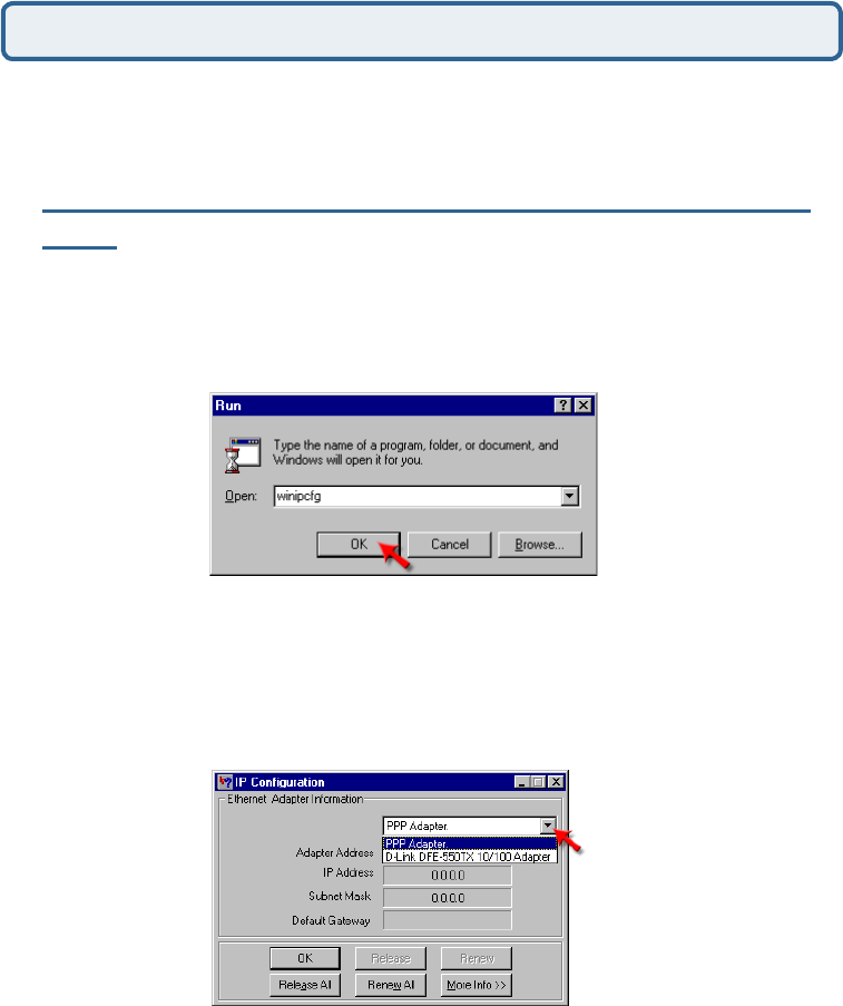
How can I find my IP Address in Windows 95, 98, or
ME?
Step 1 Click on Start, then click on Run.
Step 2 The Run Dialogue Box will appear. Type winipcfg in the window as
shown then click OK.
Step 3 The IP Configuration window will appear, displaying your Ethernet
Adapter Information.
Select your adapter from the drop down menu.
If you do not see your adapter in the drop down menu, your adapter is
not properly installed.
Step 4 After selecting your adapter, it will display your IP Address, subnet
mask, and default gateway.
Step 5 Click OK to close the IP Configuration window
Why can´t I access the web based configuration? (continued)
71
Frequently Asked Questions (continued)
Step 4 (continued) Check your IP Address. Your computer must have an IP Address
in the same range of the device you are attempting to configure. Most D-Link devices
use the 192.168.0.X range.
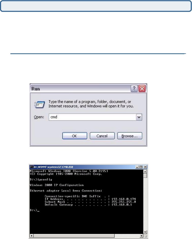
How can I find my IP Address in Windows 2000/XP?
Step 1 Click on Start and select Run.
Step 2 Type cmd then click OK.
Step 3 From the Command Prompt, enter ipconfig. It will return your IP
Address, subnet mask, and default gateway
Step 4 Type exit to close the command prompt.
Why can´t I access the web based configuration? (continued)
72
Frequently Asked Questions (continued)
Step 4 (continued) Check your IP Address. Your computer must have an IP
Address in the same range of the device you are attempting to configure. Most D-
Link devices use the 192.168.0.X range.
Make sure you take note of your computer´s Default Gateway IP Address. The
Default Gateway is the IP Address of the D-Link router. By default, it should be
192.168.0.1.
How can I assign a Static IP Address in Windows XP?
Step 1
Click on Start > Control Panel > Network and Internet Connections >
Network connections.
Step 2 See Step 2 for Windows 2000 and continue from there.
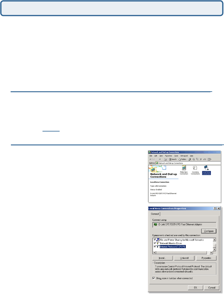
How can I assign a Static IP Address in Windows 2000?
Step 1 Right-click on My Network
Places and select Properties.
Step 2 Right-click on the Local
Area Connection which represents
your network card and select
Properties.
Highlight Internet Protocol (TCP/
IP) and click Properties.
Why can´t I access the web based configuration? (continued)
73
Frequently Asked Questions (continued)
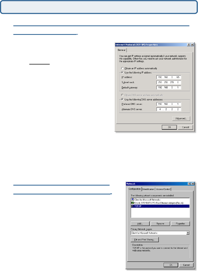
How can I assign a Static IP Address in Windows
2000? (continued)
Click Use the following IP Address and
enter an IP Address that is on the same
subnet as the LAN IP Address on your
router. Example: If the router´s LAN IP
Address is 192.168.0.1, make your IP
Address 192.168.0.X where X = 2-99.
Make sure that the number you choose
is not in use on the network.
Set the Default Gateway to be the
same as the LAN IP Address of your
router (192.168.0.1).
Set the Primary DNS to be the same
as the LAN IP address of your router
(192.168.0.1).
The Secondary DNS is not needed or enter a DNS server from your ISP.
Click OK twice. You may be asked if you want to reboot your computer. Click
Yes.
How can I assign a Static IP
Address in Windows 98/Me?
Step 1 From the desktop, right-click on the
Network Neigborhood icon (Win ME - My
Network Places) and select Properties
Highlight TCP/IP and click the Properties
button. If you have more than 1 adapter,
then there will be a TCP/IP “Binding”
for each adapter. Highlight TCP/IP >
(your network adapter) and then click
Properties.
Why can´t I access the web based configuration? (continued)
74
Frequently Asked Questions (continued)
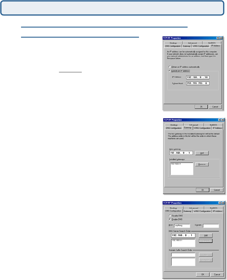
How can I assign a Static IP Address in
Windows 98/Me? (continued)
Step 2 Click Specify an IP Address.
Step 3 Click on the Gateway tab.
Enter the LAN IP Address of your router
here (192.168.0.1).
Click Add when finished.
Step 4 Click on the DNS Configuration tab.
Enter in an IP Address that is on the same
subnet as the LAN IP Address on your
router. Example: If the router´s LAN IP
Address is 192.168.0.1, make your IP
Address 192.168.0.X where X is between
2-99. Make sure that the number you choose
is not in use on the network.
Step 5 Click OK twice.
Click Enable DNS. Type in a Host (can
be any word). Under DNS server search
order, enter the LAN IP Address of your
router (192.168.0.1). Click Add.
When prompted to reboot your computer,
click Yes.
After you reboot, the computer will now
have a static, private IP Address.
Why can´t I access the web based configuration? (continued)
Step 5 Access the web management. Open your web
browser and enter the IP Address of your D-Link device in
the address bar. This should open the login page for the
web management. Follow instructions to login and complete the configuration.
75
Frequently Asked Questions (continued)
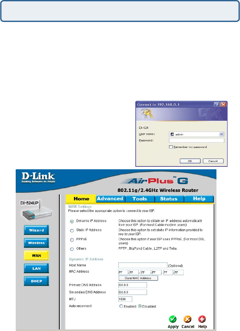
How can I setup my router to work with a Cable modem connection?
Dynamic Cable connection
(IE AT&T-BI, Cox, Adelphia, Rogers, Roadrunner, Charter, and Comcast).
Note: Please configure the router with the computer that was last connected directly
to the cable modem.
Step 1 Log into the web based configuration by typing in the IP Address of the
router (default:192.168.0.1) in your web browser. The username is admin (all
lowercase) and the password is blank (nothing).
Step 2 Click the Home tab and click the
WAN button. Dynamic IP Address is the
default value, however, if Dynamic IP Address
is not selected as the WAN type, select
Dynamic IP Address by clicking on the radio
button. Click Clone Mac Address. Click
on Apply and then Continue to save the
changes.
76
Frequently Asked Questions (continued)
How can I setup my router to work with a Cable modem connection?
(continued)
Step 3 Power cycle the cable modem and router:
Turn the cable modem off (first) . Turn the router off Leave them off for 2 minutes.**
Turn the cable modem on (first). Wait until you get a solid cable light on the cable
modem. Turn the router on. Wait 30 seconds.
** If you have a Motorola (Surf Board) modem, leave off for at least 5 minutes.
Step 4 Follow step 1 again and log back into the web configuration. Click the
Status tab and click the Device Info button. If you do not already have a public IP
Address under the WAN heading, click on the DHCP Renew and Continue buttons.
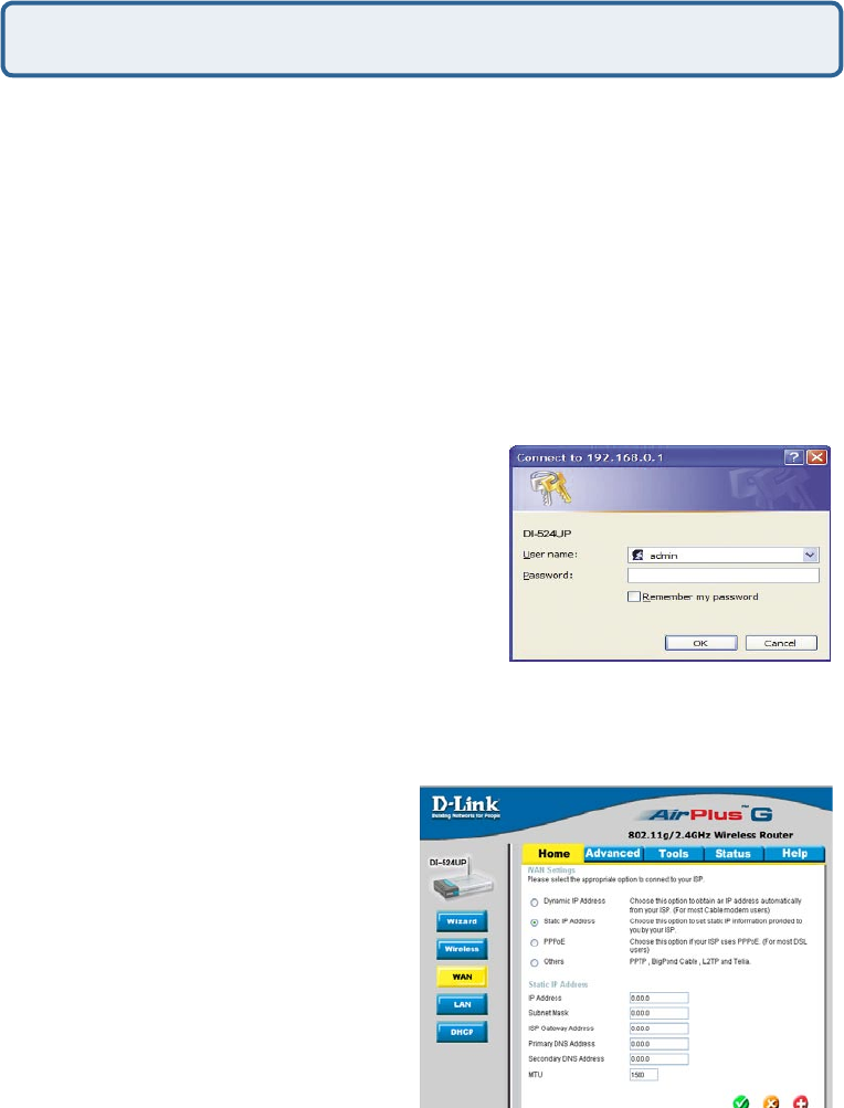
Static Cable Connection
Step 1 Log into the web based configuration
by typing in the IP Address of the router
(default:192.168.0.1) in your web browser. The
username is admin (all lowercase) and the
password is blank (nothing).
Step 2 Click the Home tab and click the WAN
button. Select Static IP Address and enter your
static settings obtained from the ISP in the fields
provided.
If you do not know your settings, you must contact your ISP.
Step 3 Click on Apply and then click
Continue to save the changes.
Step 4 Click the Status tab and click
the Device Info button. Your IP Address
information will be displayed under the
WAN heading.

77
Frequently Asked Questions (continued)
How can I setup my router to work with Earthlink DSL or any PPPoE
connection?
Make sure you disable or uninstall any PPPoE software such as WinPoet or Enternet
300 from your computer or you will not be able to connect to the Internet.
Step 1 Upgrade Firmware if needed.
(Please visit the D-Link tech support website at: http://support.dlink.com for the latest
firmware upgrade information.)
Step 2 Take a paperclip and perform a hard reset. With the unit on, use a paperclip
and hold down the reset button on the back of the unit for 10 seconds. Release it and
the router will recycle, the lights will blink, and then stabilize.
Step 3 After the router stabilizes, open your browser and enter 192.168.0.1 into
the address window and hit the Enter key. When the password dialog box appears,
enter the username admin and leave the password blank. Click OK.
If the password dialog box does not come up repeat Step 2.
Note: Do not run Wizard.
Step 4 Click on the WAN tab on left-hand side of the screen. Select PPPoE.
Step 5 Select Dynamic PPPoE (unless your ISP supplied you with a static IP
Address).
Step 6 In the username field enter ELN/username@earthlink.net and your
password, where username is your own username.
For SBC Global users, enter username@sbcglobal.net.
For Ameritech users, enter username@ameritech.net.
For BellSouth users, enter username@bellsouth.net.
For Mindspring users, enter username@mindspring.com.
For most other ISPs, enter username.
Step 7 Maximum Idle Time should be set to zero. Set MTU to 1492, unless
specified by your ISP, and set Autoreconnect to Enabled.
Note: If you experience problems accessing certain websites and/or email issues,
please set the MTU to a lower number such as 1472, 1452, etc. Contact your ISP for
more information and the proper MTU setting for your connection.
78
Step 8 Click Apply. When prompted, click Continue. Once the screen refreshes,
unplug the power to the D-Link router.
Step 9 Turn off your DSL modem for 2-3 minutes. Turn back on. Once the modem
has established a link to your ISP, plug the power back into the D-Link router. Wait
about 30 seconds and log back into the router.
Step 10 Click on the Status tab in the web configuration where you can view the
device info. Under WAN, click Connect. Click Continue when prompted. You should
now see that the device info will show an IP Address, verifying that the device has
connected to a server and has been assigned an IP Address.
How can I setup my router to work with Earthlink DSL or any PPPoE
connection? (continued)
Frequently Asked Questions (continued)
Can I use my D-Link Broadband Router to share my Internet connection
provided by AOL DSL Plus?
In most cases yes. AOL DSL+ may use PPPoE for authentication bypassing the
client software. If this is the case, then our routers will work with this service. Please
contact AOL if you are not sure.
To set up your router:
Step 1 Log into the web-based configuration (192.168.0.1) and configure the WAN
side to use PPPoE.
Step 2 Enter your screen name followed by @aol.com for the user name. Enter
your AOL password in the password box.
Step 3 You will have to set the MTU to 1400. AOL DSL does not allow for anything
higher than 1400.
Step 4 Apply settings.
Step 5 Recycle the power to the modem for 1 minute and then recycle power to the
router. Allow 1 to 2 minutes to connect.
If you connect to the Internet with a different internet service provider and want
to use the AOL software, you can do that without configuring the router’s firewall
settings. You need to configure the AOL software to connect using TCP/IP.
Go to http://www.aol.com for more specific configuration information of their software.
79
Frequently Asked Questions (continued)
How do I open ports on my router?
To allow traffic from the internet to enter your local network, you will need to open up
ports or the router will block the request.
Step 1 Open your web
browser and enter the IP
Address of your D-Link router
(192.168.0.1). Enter username
(admin) and your password
(blank by default).
Step 2 Click on Advanced
on top and then click Virtual
Server on the left side.
Step 3 Check Enabled to
activate entry.
Step 4 Enter a name for your virtual server entry.
Step 5 Next to Private IP, enter the IP Address of the computer on your local
network that you want to allow the incoming service to.
Step 6 Choose Protocol Type - either TCP, UDP, or both. If you are not sure, select
both.
Step 7 Enter the port information next to Private Port and Public Port. The private
and public ports are usually the same. The public port is the port seen from the WAN
side, and the private port is the port being used by the application on the computer
within your local network.
Step 8 Enter the Schedule information.
Step 9 Click Apply and then click Continue.
Note: Make sure DMZ host is disabled. If DMZ is enabled, it will disable all Virtual
Server entries.
Because our routers use NAT (Network Address Translation), you can only open a
specific port to one computer at a time. For example: If you have 2 web servers on
your network, you cannot open port 80 to both computers. You will need to configure
1 of the web servers to use port 81. Now you can open port 80 to the first computer
and then open port 81 to the other computer.
80
Frequently Asked Questions (continued)
What is DMZ?
Demilitarized Zone:
In computer networks, a DMZ (demilitarized zone) is a computer host or small
network inserted as a neutral zone between a company´s private network and the
outside public network. It prevents outside users from getting direct access to a
server that has company data. (The term comes from the geographic buffer zone
that was set up between North Korea and South Korea following the UN police action
in the early 1950s.) A DMZ is an optional and more secure approach to a firewall and
effectively acts as a proxy server as well.
In a typical DMZ configuration for a small company, a separate computer (or host in
network terms) receives requests from users within the private network for access
to Web sites or other companies accessible on the public network. The DMZ host
then initiates sessions for these requests on the public network. However, the DMZ
host is not able to initiate a session back into the private network. It can only forward
packets that have already been requested.
Users of the public network outside the company can access only the DMZ host. The
DMZ may typically also have the company´s Web pages so these could be served
to the outside world. However, the DMZ provides access to no other company data.
In the event that an outside user penetrated the DMZ hosts security, the Web pages
might be corrupted but no other company information would be exposed. D-Link, a
leading maker of routers, is one company that sells products designed for setting up
a DMZ
How do I configure the DMZ Host?
The DMZ feature allows you to forward all incoming ports to one computer on the
local network. The DMZ, or Demilitarized Zone, will allow the specified computer
to be exposed to the Internet. DMZ is useful when a certain application or game
does not work through the firewall. The computer that is configured for DMZ will be
completely vulnerable on the Internet, so it is suggested that you try opening ports
from the Virtual Server or Firewall settings before using DMZ.
Step 1 Find the IP address of the computer you want to use as the DMZ host.
To find out how to locate the IP Address of the computer in Windows XP/2000/ME/9x
or Macintosh operating systems please refer to Step 4 of the first question in this
section (Frequently Asked Questions).
81
Frequently Asked Questions (continued)
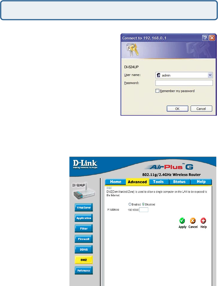
Step 2 Log into the web based configuration
of the router by typing in the IP Address
of the router (default:192.168.0.1) in your
web browser. The username is admin (all
lowercase) and the password is blank
(nothing)
How do I configure the DMZ Host? (continued)
Step 3 Click the Advanced tab and then click on the DMZ button. Select Enable
and type in the IP Address you found in step 1.
Step 4 Click Apply
and then Continue to
save the changes.
Note: When DMZ is
enabled, Virtual Server
settings will still be
effective. Remember,
you cannot forward the
same port to multiple
IP Addresses, so the
Virtual Server settings
will take priority over
DMZ settings.
82
Frequently Asked Questions (continued)
How do I open a range of ports on my DI-524UP using Firewall rules?
Step 1 Access the router’s web configuration by entering the router’s IP Address in
your web browser. The default IP Address is 192.168.0.1. Login using your password.
The default username is “admin” and the password is blank.
If you are having difficulty accessing web management, please see the first question
in this section.
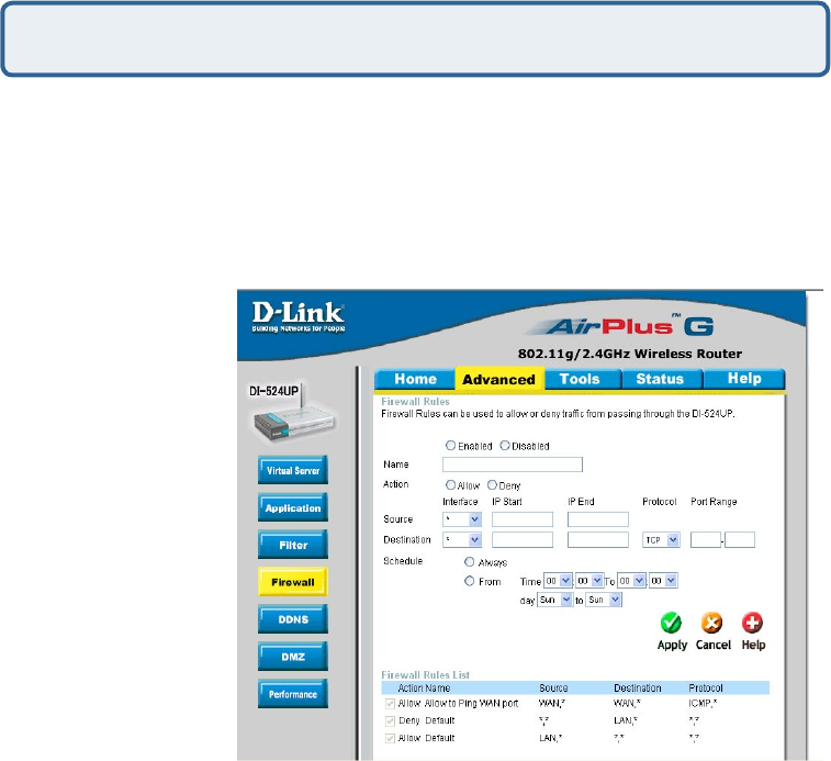
Step 2 From the web management Home page, click the Advanced tab then click
the Firewall button.
Step 3 Click on
Enabled and type in a
name for the new rule.
Step 4 Choose WAN
as the Source and
enter a range of IP
Addresses out on the
internet that you would
like this rule applied
to. If you would like
this rule to allow all
internet users to be
able to access these
ports, then put an
Asterisk in the first
box and leave the
second box empty.
Step 5 Select LAN as the Destination and enter the IP Address of the computer on
your local network that you want to allow the incoming service to. This will not work
with a range of IP Addresses.
Step 6 Enter the port or range of ports that are required to be open for the incoming
service.
Step 7 Click Apply and then click Continue.
Because our routers use NAT (Network Address Translation), you can only open a
specific port to one computer at a time. For example: If you have 2 web servers on
your network, you cannot open port 80 to both computers. You will need to configure
1 of the web servers to use port 81. Now you can open port 80 to the first computer
and then open port 81 to the other computer.
Note: Make sure DMZ host is disabled.
83
Frequently Asked Questions (continued)
What are virtual servers?
A Virtual Server is defined as a service port, and all requests to this port will be
redirected to the computer specified by the server IP. For example, if you have an
FTP Server (port 21) at 192.168.0.5, a Web server (port 80) at 192.168.0.6, and
a VPN server at 192.168.0.7, then you need to specify the following virtual server
mapping table:
Server Port Server IP Enable
21 192.168.0.5 X
80 192.168.0.6 X
1723 192.168.0.7 X
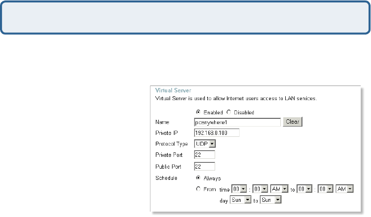
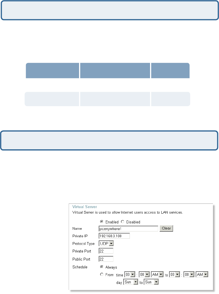
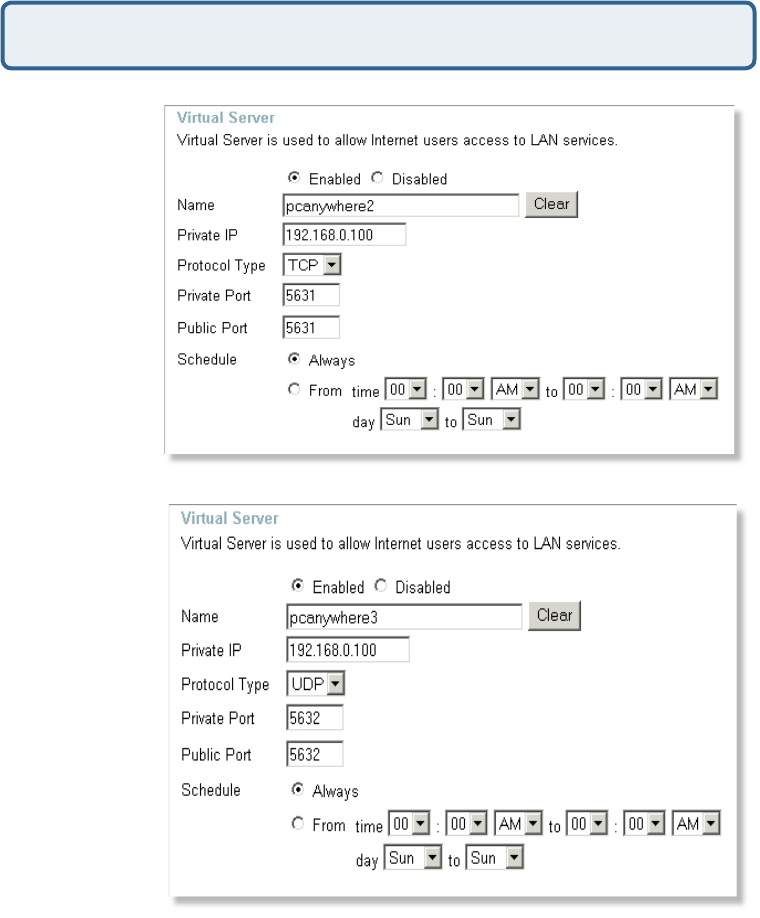
How do I use PC Anywhere with my DI-524UP router?
You will need to open 3 ports in the Virtual Server section of your D-Link router.
Step 1 Open your web browser and enter the IP Address of the router
(192.168.0.1).
Step 2 Click on Advanced at the top and then click Virtual Server on the left side.
Step 3 Enter the
information as seen
below. The Private IP
is the IP Address of the
computer on your local
network that you want
to connect to.
Step 4 The first entry
will read as shown here:
Step 5 Click Apply
and then click Continue.
84
How do I use PC Anywhere with my DI-524UP router? (continued)
Frequently Asked Questions (continued)
Step 6 Create
a second entry
as shown here:
Step 7 Click
Apply and then
click Continue.
Step 8 Create
a third and final
entry as shown
here:
Step 9 Click Apply and then click Continue.
Step 10 Run PCAnywhere from the remote site and use the WAN IP Address of the
router, not your computer´s IP Address.
85
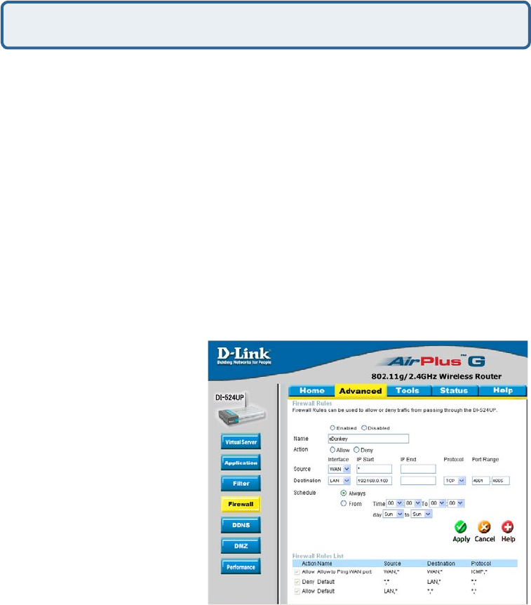
How can I use eDonkey behind my D-Link Router?
Frequently Asked Questions (continued)
You must open ports on your router to allow incoming traffic while using eDonkey.
eDonkey uses three ports (4 if using CLI):
4661 (TCP) To connect with a server
4662 (TCP) To connect with other clients
4665 (UDP) To communicate with servers other than the one you are connected to.
4663 (TCP) *Used with the command line (CLI) client when it is configured to allow
remote connections. This is the case when using a Graphical Interface (such as the
Java Interface) with the client.
Step 1 Open your web browser and enter the IP Address of your router
(192.168.0.1). Enter username (admin) and your password (leave blank).
Step 2 Click on Advanced and then click Firewall.
Step 3 Create a new firewall rule:
Click Enabled.
Enter a name (edonkey).
Click Allow.
Next to Source, select WAN
under interface. In the first box,
enter an *. Leave the second box
empty.
Next to Destination, select LAN
under interface. Enter the IP
Address of the computer you are
running eDonkey from. Leave
the second box empty. Under
Protocol, select *. In the port
range boxes, enter 4661 in the
first box and then 4665 in the
second box. Click Always or set
a schedule.
Step 4 Click Apply and then Continue.
86
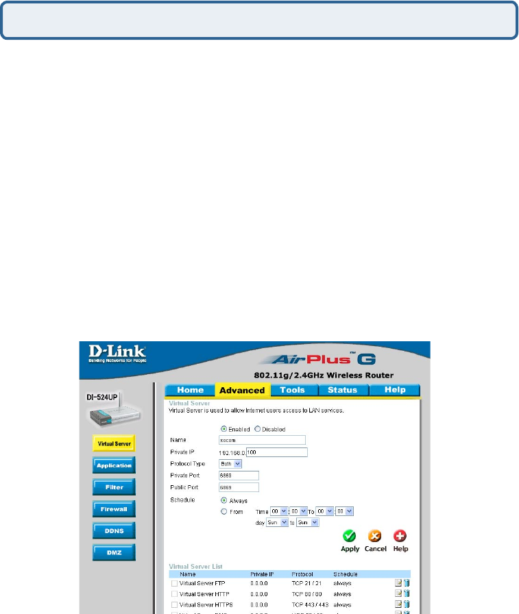
Frequently Asked Questions (continued)
To allow you to play SOCOM and hear audio, you must download the latest firmware
for the router (if needed), enable Game Mode, and open port 6869 to the IP Address
of your Playstation.
Step 1 Upgrade firmware (follow link above).
Step 2 Open your web browser and enter the IP Address of the router
(192.168.0.1). Enter username (admin) and your password (blank by default).
Step 3 Click on the Advanced tab and then click on Virtual Server on the left side.
Step 4 You will now create a new Virtual Server entry. Click Enabled and enter a
name (socom). Enter the IP Address of your Playstation for Private IP.
Step 5 For Protocol Type select Both. Enter 6869 for both the Private Port and
Public Port. Click Always. Click Apply to save changes and then Continue
Step 6 Click on the Tools tab and then Misc on the left side.
Step 7 Make sure Gaming Mode is Enabled. If not, click Enabled. Click Apply and
then Continue.
How do I set up my router for SOCOM on my Playstation 2?
87
Frequently Asked Questions (continued)
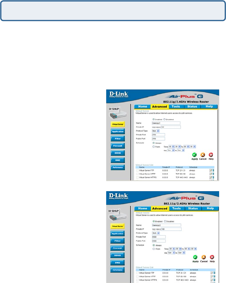
How can I use Gamespy behind my D-Link router?
Step 1 Open your web browser and enter the IP Address of the router
(192.168.0.1). Enter admin for the username and your password (blank by default).
Step 2 Click on the Advanced tab and then click Virtual Server on the left side.
Step 3 You will create 2 entries.
Step 4 Click Enabled and enter Settings:
Click Apply and then continue
Step 5 Enter 2nd entry:
Click Enabled
Click Apply and then continue.
NAME - Gamespy1
PRIVATE IP - The IP Address
of your computer that you are
running Gamespy from.
PROTOCOL TYPE - Both
PRIVATE PORT - 3783
PUBLIC PORT - 3783
SCHEDULE - Always.
NAME - Gamespy2
PRIVATE IP - The IP Address
of your computer that you
are running Gamespy from.
PROTOCOL TYPE - Both
PRIVATE PORT - 6500
PUBLIC PORT - 6500
SCHEDULE - Always.
88
Frequently Asked Questions (continued)
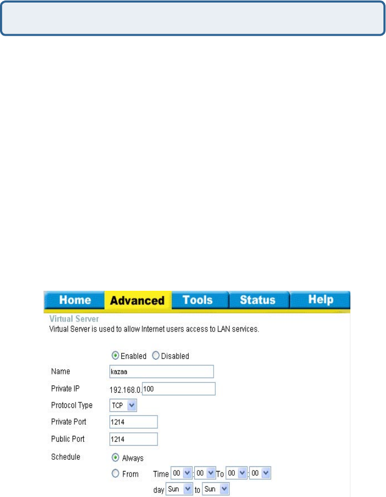
How do I configure my router for KaZaA and Grokster?
The following is for KaZaA, Grokster, and others using the FastTrack P2P file sharing
system.
In most cases, you do not have to configure anything on the router or on the Kazaa
software. If you are having problems, please follow steps below:
Step 1 Enter the IP Address of your router in a web browser (192.168.0.1).
Step 2 Enter your username (admin) and your password (blank by default).
Step 3 Click on Advanced and then click Virtual Server.
Step 4 Click Enabled and then enter a Name (kazaa for example).
Step 5 Enter the IP Address of the computer you are running KaZaA from in the
Private IP box. Select TCP for the Protocol Type.
Step 6 Enter 1214 in the Private and Public Port boxes. Click Always under
schedule or set a time range. Click Apply.
Make sure that you did not enable proxy/firewall in the KaZaA software.
89
Frequently Asked Questions (continued)
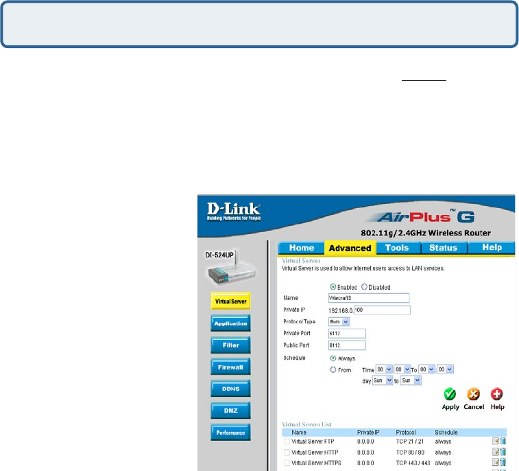
How do I configure my router to play Warcraft 3?
You must open ports on your router to allow incoming traffic while hosting a game in
Warcraft 3. To play a game, you do not have to configure your router.
Warcraft 3 (Battlenet) uses port 6112.
For the DI-604, DI-614+. DI-524UP, DI-754, DI-764, or DI-774:
Step 1 Open your web
browser and enter the IP
Address of your router
(192.168.0.1). Enter username
(admin) and your password
(leave blank).
Step 2 Click on Advanced
and then click Virtual Server.
Step 3 Create a new entry:
Click Enabled. Enter a name
(warcraft3). Private IP - Enter
the IP Address of the computer
you want to host the game.
Select Both for Protocol Type
Enter 6112 for both Private Port
and Public Port Click Always or
set a schedule.
Step 4 Click Apply and then Continue.
Note: If you want multiple computers from you LAN to play in the same game that
you are hosting, then repeat the steps above and enter the IP Addresses of the other
computers. You will need to change ports. Computer #2 can use port 6113, computer
#3 can use 6114, and so on.
You will need to change the port information within the Warcraft 3 software for
computers #2 and up.
Configure the Game Port information on each computer:
Start Warcraft 3 on each computer, click Options > Gameplay. Scroll down and you
should see Game Port. Enter the port number as you entered in the above steps.
90
Frequently Asked Questions (continued)
How do I use NetMeeting with my D-Link Router?
Unlike most TCP/IP applications, NetMeeting uses DYNAMIC PORTS instead of
STATIC PORTS. That means that each NetMeeting connection is somewhat different
than the last. For instance, the HTTP web site application uses port 80. NetMeeting
can use any of over 60,000 different ports.
All broadband routers using (only) standard NAT and all internet sharing programs
like Microsoft ICS that use (only) standard NAT will NOT work with NetMeeting or
other h.323 software packages.
The solution is to put the router in DMZ.
Note: A few hardware manufacturers have taken it on themselves to actually provide
H.323 compatibility. This is not an easy task since the router must search each
incoming packet for signs that it might be a netmeeting packet. This is a whole lot
more work than a router normally does and may actually be a weak point in the
firewall. D-Link is not one of the manufacturers.
To read more on this visit http://www.HomenetHelp.com
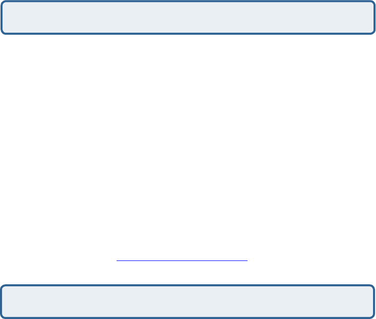
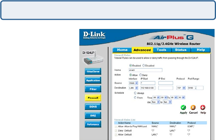
How do I set up my router to use iChat? -for Macintosh users-
You must open ports on your router to allow incoming traffic while using iChat.
iChat uses the following ports: 5060 (UDP) 5190 (TCP) File Sharing 16384-16403
(UDP) To video conference with other clients
Step 1 Open your web browser and enter the IP Address of your router
(192.168.0.1). Enter username (admin) and your password (leave blank).
Step 2 Click on Advanced and then click Firewall.
91
Frequently Asked Questions (continued)
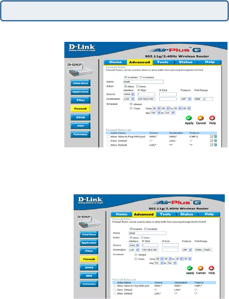
Step 3 Create a new firewall rule:
Leave the second box empty. Under Protocol, select UDP. In the port range boxes,
enter 5060 in the first box and leave the second box empty.
Click Always or set a schedule.
Step 4 Click Apply and
then Continue.
Step 5
Repeat steps 3 and 4
enter ichat2 and open
ports 16384-16403 (UDP).
How do I set up my router to use iChat? -for Macintosh users-
(continued)
Click Enabled.
Enter a name
(ichat1).
Click Allow.
Next to Source,
select WAN under
interface.
In the first box,
enter an *.
Leave the second
box empty.
Next to Destination,
select LAN under
interface.
Enter the IP
Address of the
computer you are running iChat from.
92
Frequently Asked Questions (continued)
If using Mac OS X Firewall, you may need to temporarily turn off the firewall in
the Sharing preference pane on both computers.
To use the Mac OS X Firewall, you must open the same ports as in the router:
Step 1 Choose Apple menu > System Preferences.
Step 2 Choose View > Sharing.
Step 3 Click the Firewall tab.
Step 4 Click New.
Step 5 Choose Other from the Port Name pop-up menu.
Step 6 In the Port Number, Range or Series field, type in: 5060, 16384-16403.
Step 7 In the Description field type in: iChat AV
Step 8 Click OK.
For File Sharing:
Step 1 Click on Advanced
and then Virtual Server.
Step 2 Check Enabled to
activate entry.
Step 3 Enter a name for your
virtual server entry (ichat3).
Step 4 Next to Private
IP, enter the IP Address of
the computer on your local
network that you want to allow
the incoming service to.
Step 5 Select TCP for
Protocol Type.
Step 6 Enter 5190 next to Private Port and Public Port.
Stsp 7 Click Always or configure a schedule.
Step 8 Click Apply and then Continue.
How do I set up my router to use iChat? -for Macintosh users-
(continued)

93
Frequently Asked Questions (continued)
How do I send or receive a file via iChat when the Mac OSX firewall is
active? -for Macintosh users- Mac OS X 10.2 and later
“iChat cannot send or receive a file when the Mac OS X firewall is active in its default
state. If you have opened the AIM port, you may be able to receive a file but not send
them.
In its default state, the Mac OS X firewall blocks file transfers using iChat or America
Online AIM software. If either the sender or receiver has turned on the Mac OS X fire-
wall, the transfer may be blocked.
The simplest workaround is to temporarily turn off the firewall in the Sharing preference
pane on both computers. This is required for the sender. However, the receiver may
keep the firewall on if the AIM port is open. To open the AIM port:
If you do not want to turn off the firewall at the sending computer, a different file sharing
service may be used instead of iChat. The types of file sharing available in Mac OS X
are outlined in technical document 106461, “Mac OS X: File Sharing” in the AppleCare
Knowledge base online.
Note: If you use a file sharing service when the firewall is turned on, be sure to click
the Firewall tab and select the service you have chosen in the “Allow” list. If you do not
do this, the firewall will also block the file sharing service. “
The following information is from the online Macintosh AppleCare knowledge base:
Step 1 Choose Apple menu > System Preferences.
Step 2 Choose View > Sharing.
Step 3 Click the Firewall tab.
Step 4 Click New.
Step 5 Choose AOL IM from the Port Name pop-up menu. The number
5190 should already be filled in for you.
Step 6 Click OK.
94
What is NAT?
NAT stands for Network Address Translator. It is proposed and described in
RFC-1631 and is used for solving the IP Address depletion problem. Basically, each
NAT box has a table consisting of pairs of local IP Addresses and globally unique
addresses, by which the box can “translate” the local IP Addresses to global address
and vice versa. Simply put, it is a method of connecting multiple computers to the
Internet (or any other IP network) using one IP Address.
D-Link´s broadband routers (ie: DI-604) support NAT. With proper configuration,
multiple users can access the Internet using a single account via the NAT device.
For more information on RFC-1631: The IP Network Address Translator (NAT), visit
http://www.faqs.org/rfcs/rfc1631.html
Frequently Asked Questions (continued)

95
You can find software updates and user documentation on the D-Link website.
D-Link provides free technical support for customers within the United States and
within Canada for the duration of the warranty period on this product.
U.S. and Canadian customers can contact D-Link technical support through our web
site, or by phone.
Tech Support for customers within the United States:
D-Link Technical Support over the Telephone:
(877) 453-5465
24 hours a day, seven days a week.
D-Link Technical Support over the Internet:
http://support.dlink.com
email:support@dlink.com
Tech Support for customers within Canada:
D-Link Technical Support over the Telephone:
(800) 361-5265
Monday to Friday 8:30am to 9:00pm EST
D-Link Technical Support over the Internet:
http://support.dlink.ca
email:support@dlink.ca
When contacting technical support, please provide the following information:
• Serial number of the unit
• Model number or product name
• Software type and version number
Technical Support
96
Subject to the terms and conditions set forth herein, D-Link Systems, Inc. (“D-Link”) provides this Limited
warranty for its product only to the person or entity that originally purchased the product from:
• D-Link or its authorized reseller or distributor and
• Products purchased and delivered within the fifty states of the United States, the District of Columbia,
U.S. Possessions or Protectorates, U.S. Military Installations, addresses with an APO or FPO.
Limited Warranty: D-Link warrants that the hardware portion of the D-Link products described below will
be free from material defects in workmanship and materials from the date of original retail purchase of the
product, for the period set forth below applicable to the product type (“Warranty Period”), except as otherwise
stated herein.
3-Year Limited Warranty for the Product(s) is defined as follows:
• Hardware (excluding power supplies and fans) Three (3) Years
• Power Supplies and Fans One (1) Year
• Spare parts and spare kits Ninety (90) days
D-Link’s sole obligation shall be to repair or replace the defective Hardware during the Warranty Period at
no charge to the original owner or to refund at D-Link’s sole discretion. Such repair or replacement will be
rendered by D-Link at an Authorized D-Link Service Office. The replacement Hardware need not be new or
have an identical make, model or part. D-Link may in its sole discretion replace the defective Hardware (or
any part thereof) with any reconditioned product that D-Link reasonably determines is substantially equivalent
(or superior) in all material respects to the defective Hardware. Repaired or replacement Hardware will be
warranted for the remainder of the original Warranty Period from the date of original retail purchase. If a
material defect is incapable of correction, or if D-Link determines in its sole discretion that it is not practical to
repair or replace the defective Hardware, the price paid by the original purchaser for the defective Hardware
will be refunded by D-Link upon return to D-Link of the defective Hardware. All Hardware (or part thereof)
that is replaced by D-Link, or for which the purchase price is refunded, shall become the property of D-Link
upon replacement or refund.
Limited Software Warranty: D-Link warrants that the software portion of the product (“Software”) will
substantially conform to D-Link’s then current functional specifications for the Software, as set forth in the
applicable documentation, from the date of original retail purchase of the Software for a period of ninety (90)
days (“Warranty Period”), provided that the Software is properly installed on approved hardware and operated
as contemplated in its documentation. D-Link further warrants that, during the Warranty Period, the magnetic
media on which D-Link delivers the Software will be free of physical defects. D-Link’s sole obligation shall
be to replace the non-conforming Software (or defective media) with software that substantially conforms
to D-Link’s functional specifications for the Software or to refund at D-Link’s sole discretion. Except as
otherwise agreed by D-Link in writing, the replacement Software is provided only to the original licensee,
and is subject to the terms and conditions of the license granted by D-Link for the Software. Software will
be warranted for the remainder of the original Warranty Period from the date or original retail purchase. If
a material non-conformance is incapable of correction, or if D-Link determines in its sole discretion that it
is not practical to replace the non-conforming Software, the price paid by the original licensee for the non-
conforming Software will be refunded by D-Link; provided that the non-conforming Software (and all copies
thereof) is first returned to D-Link. The license granted respecting any Software for which a refund is given
automatically terminates.
Non-Applicability of Warranty: The Limited Warranty provided hereunder for hardware and software of D-
Link’s products will not be applied to and does not cover any refurbished product and any product purchased
through the inventory clearance or liquidation sale or other sales in which D-Link, the sellers, or the liquidators
expressly disclaim their warranty obligation pertaining to the product and in that case, the product is being
sold “As-Is” without any warranty whatsoever including, without limitation, the Limited Warranty as described
herein, notwithstanding anything stated herein to the contrary.
Submitting A Claim: The customer shall return the product to the original purchase point based on its return
policy. In case the return policy period has expired and the product is within warranty, the customer shall
submit a claim to D-Link as outlined below:
Warranty and Registration
(USA only)

97
• The customer must submit with the product as part of the claim a written description of the Hardware
defect or Software nonconformance in sufficient detail to allow D-Link to confirm the same.
• The original product owner must obtain a Return Material Authorization (“RMA”) number from
the Authorized D-Link Service Office and, if requested, provide written proof of purchase of the
product (such as a copy of the dated purchase invoice for the product) before the warranty service
is provided.
• After an RMA number is issued, the defective product must be packaged securely in the original
or other suitable shipping package to ensure that it will not be damaged in transit, and the RMA
number must be prominently marked on the outside of the package. Do not include any manuals
or accessories in the shipping package. D-Link will only replace the defective portion of the Product
and will not ship back any accessories.
• The customer is responsible for all in-bound shipping charges to D-Link. No Cash on Delivery
(“COD”) is allowed. Products sent COD will either be rejected by D-Link or become the property
of D-Link. Products shall be fully insured by the customer. D-Link will not be held responsible for
any packages that are lost in transit to D-Link. The repaired or replaced packages will be shipped
to the customer via UPS Ground or any common carrier selected by D-Link, with shipping charges
prepaid. Expedited shipping is available if shipping charges are prepaid by the customer and upon
request.
• Return Merchandise Ship-To Address
USA: 17595 Mt. Herrmann, Fountain Valley, CA 92708
Canada: 2180 Winston Park Drive, Oakville, ON, L6H 5W1 (Visit http://www.dlink.ca for detailed warranty
information within Canada)
D-Link may reject or return any product that is not packaged and shipped in strict compliance with the
foregoing requirements, or for which an RMA number is not visible from the outside of the package. The
product owner agrees to pay D-Link’s reasonable handling and return shipping charges for any product that
is not packaged and shipped in accordance with the foregoing requirements, or that is determined by D-Link
not to be defective or non-conforming.
What Is Not Covered: This limited warranty provided by D-Link does not cover: Products, if in D-Link’s
judgment, have been subjected to abuse, accident, alteration, modification, tampering, negligence, misuse,
faulty installation, lack of reasonable care, repair or service in any way that is not contemplated in the
documentation for the product, or if the model or serial number has been altered, tampered with, defaced or
removed; Initial installation, installation and removal of the product for repair, and shipping costs; Operational
adjustments covered in the operating manual for the product, and normal maintenance; Damage that occurs
in shipment, due to act of God, failures due to power surge, and cosmetic damage; Any hardware, software,
firmware or other products or services provided by anyone other than D-Link; Products that have been
purchased from inventory clearance or liquidation sales or other sales in which D-Link, the sellers, or the
liquidators expressly disclaim their warranty obligation pertaining to the product. Repair by anyone other
than D-Link or an Authorized D-Link Service Office will void this Warranty.
Disclaimer of Other Warranties: EXCEPT FOR THE LIMITED WARRANTY SPECIFIED HEREIN, THE
PRODUCT IS PROVIDED “AS-IS” WITHOUT ANY WARRANTY OF ANY KIND WHATSOEVER INCLUDING,
WITHOUT LIMITATION, ANY WARRANTY OF MERCHANTABILITY, FITNESS FOR A PARTICULAR
PURPOSE AND NON-INFRINGEMENT. IF ANY IMPLIED WARRANTY CANNOT BE DISCLAIMED IN ANY
TERRITORY WHERE A PRODUCT IS SOLD, THE DURATION OF SUCH IMPLIED WARRANTY SHALL BE
LIMITED TO NINETY (90) DAYS. EXCEPT AS EXPRESSLY COVERED UNDER THE LIMITED WARRANTY
PROVIDED HEREIN, THE ENTIRE RISK AS TO THE QUALITY, SELECTION AND PERFORMANCE OF
THE PRODUCT IS WITH THE PURCHASER OF THE PRODUCT.
Limitation of Liability: TO THE MAXIMUM EXTENT PERMITTED BY LAW, D-LINK IS NOT LIABLE UNDER
ANY CONTRACT, NEGLIGENCE, STRICT LIABILITY OR OTHER LEGAL OR EQUITABLE THEORY FOR ANY
LOSS OF USE OF THE PRODUCT, INCONVENIENCE OR DAMAGES OF ANY CHARACTER, WHETHER
DIRECT, SPECIAL, INCIDENTAL OR CONSEQUENTIAL (INCLUDING, BUT NOT LIMITED TO, DAMAGES
FOR LOSS OF GOODWILL, LOSS OF REVENUE OR PROFIT, WORK STOPPAGE, COMPUTER FAILURE
OR MALFUNCTION, FAILURE OF OTHER EQUIPMENT OR COMPUTER PROGRAMS TO WHICH D-LINK’S
PRODUCT IS CONNECTED WITH, LOSS OF INFORMATION OR DATA CONTAINED IN, STORED ON, OR
INTEGRATED WITH ANY PRODUCT RETURNED TO D-LINK FOR WARRANTY SERVICE) RESULTING
FROM THE USE OF THE PRODUCT, RELATING TO WARRANTY SERVICE, OR ARISING OUT OF ANY
BREACH OF THIS LIMITED WARRANTY, EVEN IF D-LINK HAS BEEN ADVISED OF THE POSSIBILITY OF SUCH
DAMAGES. THE SOLE REMEDY FOR A BREACH OF THE FOREGOING LIMITED WARRANTY IS REPAIR,
REPLACEMENT OR REFUND OF THE DEFECTIVE OR NON-CONFORMING PRODUCT. THE MAXIMUM

98
Governing Law: This Limited Warranty shall be governed by the laws of the State of California. Some states
do not allow exclusion or limitation of incidental or consequential damages, or limitations on how long an
implied warranty lasts, so the foregoing limitations and exclusions may not apply. This limited warranty provides
specific legal rights and the product owner may also have other rights which vary from state to state.
Trademarks: D-Link is a registered trademark of D-Link Systems, Inc. Other trademarks or registered
trademarks are the property of their respective manufacturers or owners.
Copyright Statement: No part of this publication or documentation accompanying this Product
may be reproduced in any form or by any means or used to make any derivative such as translation,
transformation, or adaptation without permission from D-Link Corporation/D-Link Systems, Inc., as
stipulated by the United States Copyright Act of 1976. Contents are subject to change without prior notice.
Copyright© 2002 by D-Link Corporation/D-Link Systems, Inc. All rights reserved.
CE Mark Warning: This is a Class B product. In a domestic environment, this product may cause radio
interference, in which case the user may be required to take adequate measures.
FCC Statement: This equipment has been tested and found to comply with the limits for a Class B digital
device, pursuant to part 15 of the FCC Rules. These limits are designed to provide reasonable protection
against harmful interference in a residential installation. This equipment generates, uses, and can radiate
radio frequency energy and, if not installed and used in accordance with the instructions, may cause harmful
interference to radio communication. However, there is no guarantee that interference will not occur in a
particular installation. If this equipment does cause harmful interference to radio or television reception,
which can be determined by turning the equipment off and on, the user is encouraged to try to correct the
interference by one or more of the following measures:
• Reorient or relocate the receiving antenna.
• Increase the separation between the equipment and receiver.
• Connect the equipment into an outlet on a circuit different from that to which the receiver is
connected.
• Consult the dealer or an experienced radio/TV technician for help.
For detailed warranty outside the United States, please contact corresponding local
D-Link office.
Register your D-Link product online at http://support.dlink.com/register/
FCC Caution:
(1) The devices are restricted to indoor operations within the 5.15 to 5.25GHz range. (2) For this
device to operate in the 5.15 to 5.25GHz range, the devices must use integral antennas.
This device complies with Part 15 of the FCC Rules. Operation is subject to the following two
conditions: (1) This device may not cause harmful interference, and (2) this device must accept any
interference received, including interference that may cause undesired operation.
IMPORTANT NOTE:
FCC Radiation Exposure Statement:
This equipment complies with FCC radiation exposure limits set forth for an uncontrolled
environment. The antenna(s) used for this equipment must be installed to provide a separation
distance of at least eight inches (20 cm) from all persons.
This equipment must not be operated in conjunction with any other antenna.
LIABILITY OF D-LINK UNDER THIS WARRANTY IS LIMITED TO THE PURCHASE PRICE OF THE
PRODUCT COVERED BY THE WARRANTY. THE FOREGOING EXPRESS WRITTEN WARRANTIES
AND REMEDIES ARE EXCLUSIVE AND ARE IN LIEU OF ANY OTHER WARRANTIES OR REMEDIES,
EXPRESS, IMPLIED OR STATUTORY.
The manufacturer is not responsible for any radio or TV interference caused by unauthorized
modifications to this equipment; such modifications could void the user’s authority to operate the
equipment.