D Link DI524UPA1 IEEE 802.11 b/g Wireless Router User Manual DI 524UP manual 0914
D Link Corporation IEEE 802.11 b/g Wireless Router DI 524UP manual 0914
UserManual.wiki
>
D Link
>
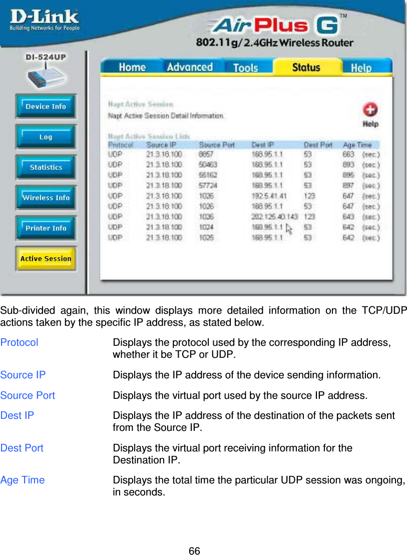
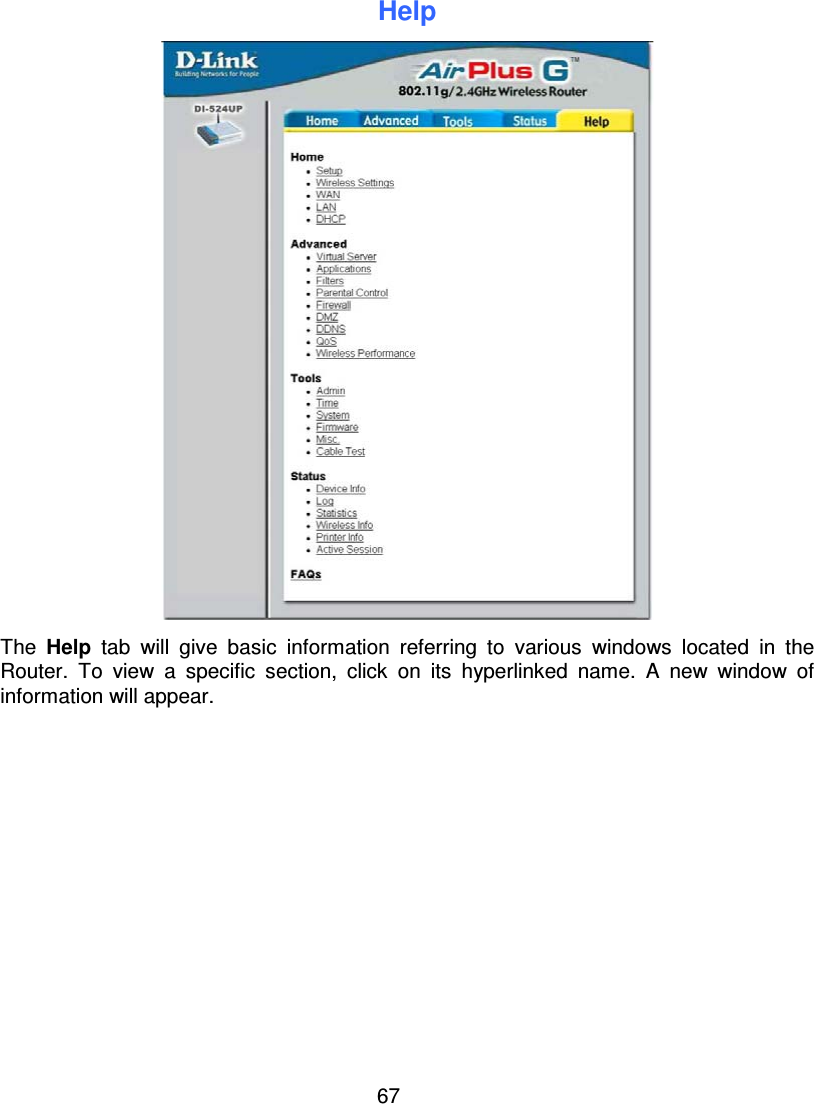
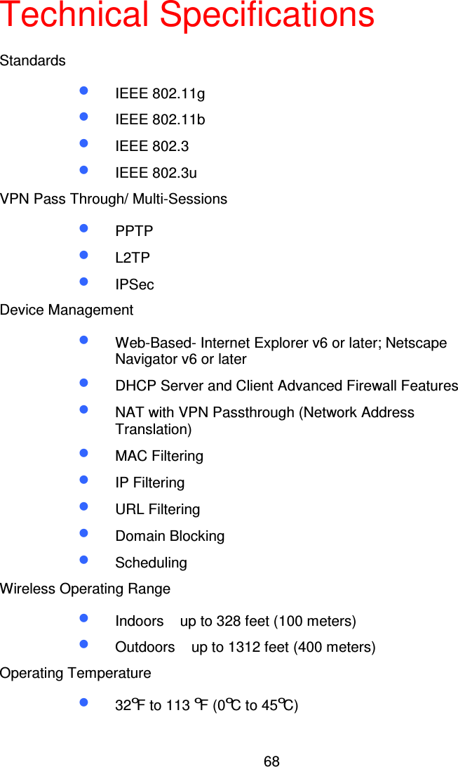
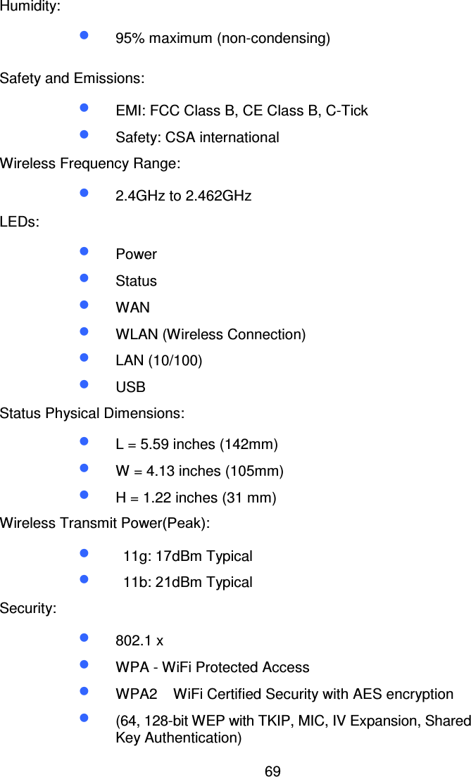
DI524UPA1 User Manual
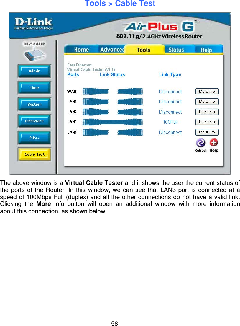
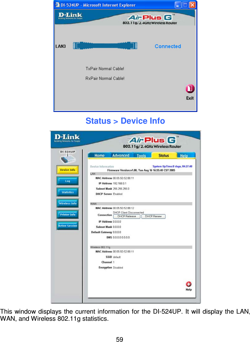
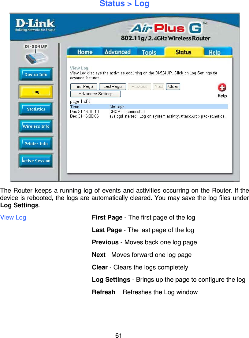
User Manual
Navigation menu
Upload a User Manual
Namespaces
Wiki Guide
HTML
PDF
Info
Views
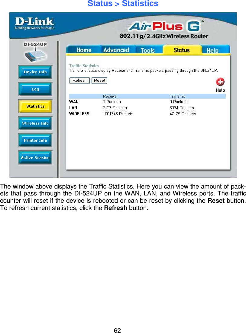
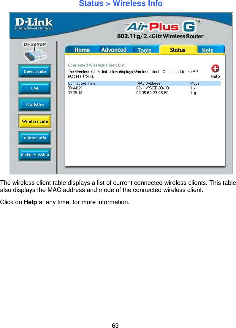
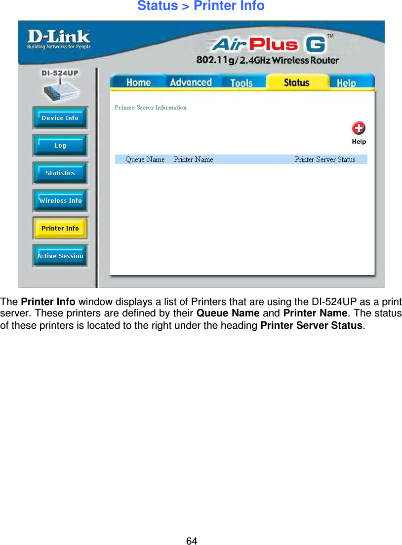
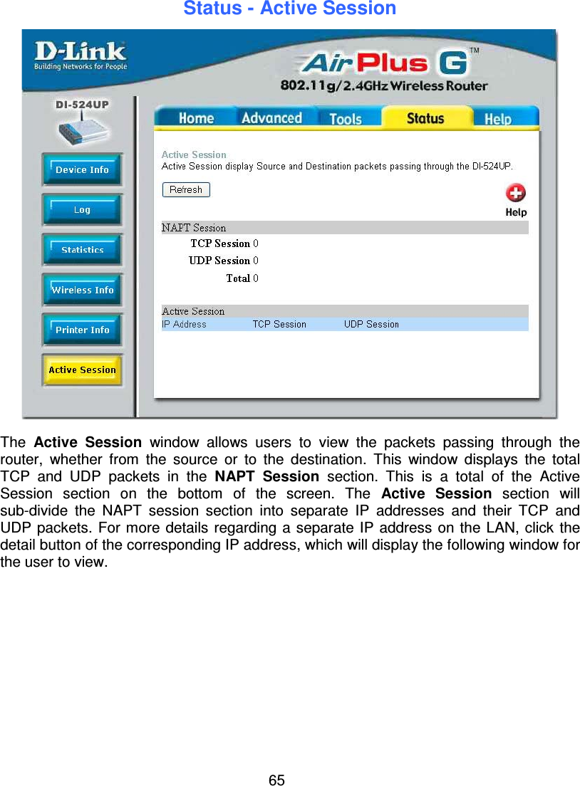
User Manual
Discussion / Help
Navigation