D Link DIR450A1 802.11g Mini PCI Card User Manual WLG 1302 IC
D Link Corporation 802.11g Mini PCI Card WLG 1302 IC
UserManual.wiki
>
D Link
>
DIR450A1 User Manual
User manual
Navigation menu
Upload a User Manual
Namespaces
Wiki Guide
HTML
PDF
Info
Views
User Manual
Discussion / Help
Navigation
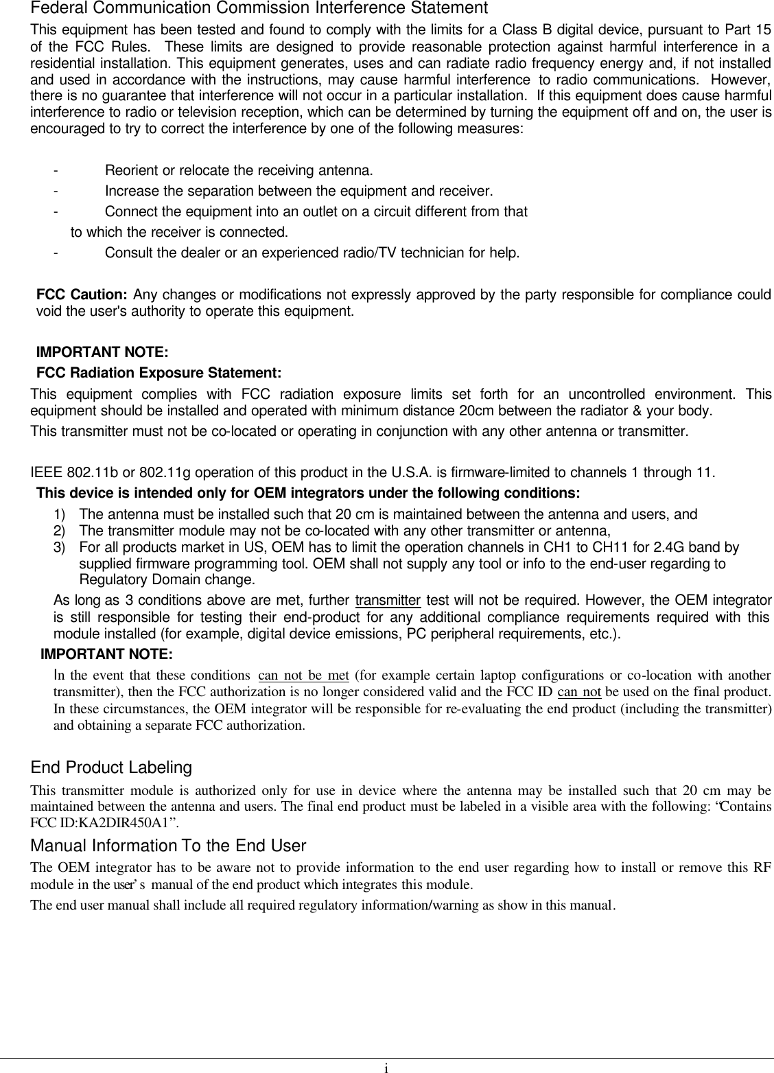
![ii Industry Canada statement: This device complies with RSS-210 of the Industry Canada Rules. Operation is subject to the following two conditions: (1) This device may not cause harmful interference, and (2) this device must accept any interference received, including interference that may cause undesired operation. The Class [B] digital apparatus meets all requirements of the Canadian Interference-Causing Equipment Regulation. Cet appareil numerique de la class [B] respecte toutes les exigences du Reglement sur le materiel brouilleur du Canada. IMPORTANT NOTE: Radiation Exposure Statement: This equipment complies with IC radiation exposure limits set forth for an uncontrolled environment. This equipment should be installed and operated with minimum distance 20cm between the radiator & your body. This device has been designed to operate with an antenna having a maximum gain of 2 dB. Antenna having a higher gain is strictly prohibited per regulations of Industry Canada. The required antenna impedance is 50 ohms.](https://usermanual.wiki/D-Link/DIR450A1/User-Guide-742069-Page-3.png)