D Link DIR625C1 D-Link DIR-625 RANGEBOOSTER N ROUTER User Manual Manual Part1
D Link Corporation D-Link DIR-625 RANGEBOOSTER N ROUTER Manual Part1
D Link >
Contents
- 1. Manual Part1
- 2. Manual Part2
Manual Part1

2D-Link DIR-625 User Manual
Table of Contents
Product Overview ........................................................4
Package Contents....................................................4
System Requirements ............................................. 4
Introduction ..............................................................5
Features ...................................................................6
Hardware Overview .................................................7
Connections .......................................................7
LEDs ..................................................................8
Installation ....................................................................9
Before you Begin ..................................................... 9
Wireless Installation Considerations ......................10
Connect to Cable/DSL/Satellite Modem ................11
Connect to Another Router ....................................12
Getting Started ......................................................14
Configuration ............................................................. 15
Web-based Configuration Utility ............................ 15
Setup Wizard ................................................... 16
Manual Configuration ....................................... 20
Dynamic (Cable)...........................................20
PPPoE (DSL) ...............................................21
PPTP ............................................................22
L2TP .............................................................24
Static (assigned by ISP) ...............................26
Big Pond ....................................................... 27
Wireless Settings .............................................28
Network Settings .............................................. 30
DHCP Server Settings .................................31
DHCP Reservation ....................................... 32
Virtual Server ................................................... 34
Port Forwarding ...............................................36
Application Rules .............................................37
QoS Engine .....................................................38
Network Filters ................................................. 39
Access Control ................................................. 40
Access Control Wizard .................................40
Website Filters .................................................43
Inbound Filters .................................................44
Firewall Settings ............................................... 45
Application Level Gateway (ALG)
Configuration....................................................46
VPN Passthrough ......................................... 46
RTSP ............................................................ 46
H.323 ............................................................46
SIP (VoIP) .....................................................46
MMS .............................................................46
Advanced Wireless Settings ............................47
WISH ...............................................................48
Wi-Fi Protected Setup ...................................... 50
Advanced Network Settings .............................52
UPnP ............................................................52
Internet Ping Block .......................................52
Internet Port Speed ...................................... 52
Table of Contents

3D-Link DIR-625 User Manual
Table of Contents
Multicast Streams .........................................52
Administrator Settings ...................................... 53
Change Password ........................................ 53
Remote Management ...................................53
Time Settings ................................................... 54
SysLog ............................................................. 55
Email Settings .................................................. 56
System Settings ............................................... 57
Update Firmware ............................................. 58
DDNS ............................................................... 59
System Check .................................................. 60
Schedules ........................................................61
Device Information ...........................................62
Log ................................................................... 63
Stats ................................................................. 64
Internet Sessions .............................................65
Wireless ...........................................................67
WISH Sessions ................................................ 68
Support ............................................................69
Wireless Security .......................................................70
What is WEP? ........................................................70
What is WPA? ........................................................ 71
Wireless Security Setup Wizard ............................72
Configure WEP ...................................................... 75
Configure WPA-Personal (PSK) .............................76
Configure WPA-Enterprise (RADIUS) ....................77
Connect to a Wireless Network ................................ 79
Using Windows® XP ...............................................79
Configure WEP ...................................................... 80
Configure WPA-PSK .............................................. 82
Troubleshooting ......................................................... 84
Wireless Basics ......................................................... 88
What is Wireless? .................................................. 89
Tips ........................................................................91
Wireless Modes ..................................................... 92
Networking Basics .................................................... 93
Check your IP address ..........................................93
Statically Assign an IP address ............................. 94
Technical Specifications ........................................... 95
Contacting Technical Support .................................. 96
Warranty .....................................................................97
Registration ..............................................................103
4D-Link DIR-625 User Manual
Section 1 - Product Overview
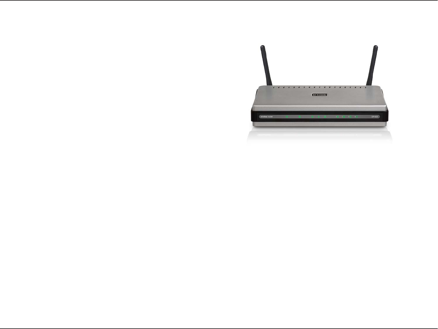
• D-Link DIR-625 RangeBooster N™ Router
• 2 Detachable Antennas
• Power Adapter
• CAT5 Ethernet Cable
• CD-ROM with Installation Wizard, User Manual,
and Special Offers
System Requirements
• Ethernet-based Cable or DSL Modem
• Computers with Windows®, Macintosh®, or Linux-based operating systems with an installed Ethernet
adapter
• Internet Explorer Version 6.0, Mozilla 1.7.12 (5.0), or Firefox 1.5 and above (for configuration)
• Installation Wizard requires Windows® XP with Service Pack 2
Product Overview
Package Contents
Note: Using a power supply with a different voltage rating than the one included
with the DIR-625 will cause damage and void the warranty for this product.

5D-Link DIR-625 User Manual
Section 1 - Product Overview
Introduction
TOTAL PERFORMANCE
Combines award winning router features and Draft 802.11n wireless technology to provide the best wireless performance
TOTAL SECURITY
The most complete set of security features including Active Firewall and WPA2 to protect your network against outside
intruders
TOTAL COVERAGE
Provides greater wireless signal rates even at farther distances for best-in-class Whole Home Coverage.
ULTIMATE PERFORMANCE
The D-Link RangeBooster N™ Router (DIR-625) is a draft 802.11n compliant device that delivers real world performance of
up to 650% faster than an 802.11g wireless connection (also faster than a 100Mbps wired Ethernet connection). Create a
secure wireless network to share photos, files, music, video, printers, and network storage throughout your home. Connect the
RangeBooster N™ Router to a cable or DSL modem and share your high-speed Internet access with everyone on the network.
In addition, this Router includes a Quality of Service (QoS) engine that keeps digital phone calls (VoIP) and online gaming
smooth and responsive, providing a better Internet experience.
EXTENDED WHOLE HOME COVERAGE
Powered by RangeBooster N™ technology, this high performance router provides superior Whole Home Coverage while reducing
dead spots. The RangeBooster N™ Router is designed for use in bigger homes and for users who demand higher performance
networking. Add a RangeBooster N™ notebook or desktop adapter and stay connected to your network from virtually anywhere
in your home.
TOTAL NETWORK SECURITY
The RangeBooster N™ Router supports all of the latest wireless security features to prevent unauthorized access, be it from
over the wireless network or from the Internet. Support for WPA and WEP standards ensure that you’ll be able to use the best
possible encryption method, regardless of your client devices. In addition, this RangeBooster N™ Router utilizes dual active
firewalls (SPI and NAT) to prevent potential attacks from across the Internet.
* Maximum wireless signal rate derived from IEEE Standard 802.11g and Draft 802.11n specifications. Actual data throughput will vary. Network conditions and
environmental factors, including volume of network traffic, building materials and construction, and network overhead, lower actual data throughput rate. Environmental
conditions will adversely affect wireless signal range.

6D-Link DIR-625 User Manual
Section 1 - Product Overview
• Faster Wireless Networking - The DIR-625 provides up to 300Mbps* wireless connection with other
802.11n wireless clients. This capability allows users to participate in real-time activities online, such as
video streaming, online gaming, and real-time audio. The performance of this 802.11n wireless router
gives you the freedom of wireless networking at speeds 650% faster than 802.11g.
• Compatible with 802.11b and 802.11g Devices - The DIR-625 is still fully compatible with the IEEE
802.11b standard, so it can connect with existing 802.11b PCI, USB and Cardbus adapters.
• Advanced Firewall Features - The Web-based user interface displays a number of advanced network
management features including:
• Content Filtering - Easily applied content filtering based on MAC Address, URL, and/or
Domain Name.
• Filter Scheduling - These filters can be scheduled to be active on certain days or for a
duration of hours or minutes.
• Secure Multiple/Concurrent Sessions - The DIR-625 can pass through VPN sessions. It
supports multiple and concurrent IPSec and PPTP sessions, so users behind the DIR-625
can securely access corporate networks.
• User-friendly Setup Wizard - Through its easy-to-use Web-based user interface, the DIR-625 lets you
control what information is accessible to those on the wireless network, whether from the Internet or from
your company’s server. Configure your router to your specific settings within minutes.
* Maximum wireless signal rate derived from IEEE Standard 802.11g and Draft 802.11n specifications. Actual data throughput will vary. Network conditions and
environmental factors, including volume of network traffic, building materials and construction, and network overhead, lower actual data throughput rate. Environmental
conditions will adversely affect wireless signal range.
Features
7D-Link DIR-625 User Manual
Section 1 - Product Overview
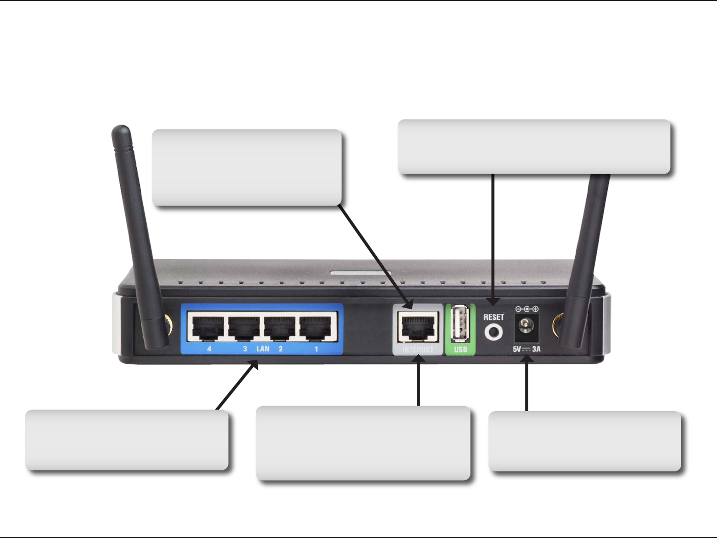
Hardware Overview
Connections
USB
Connect a USB 1.1 or 2.0 flash
drive to configure the wireless
settings using WCN.
Reset
Pressing the Reset button restores the router to
its original factory default settings.
LAN Ports (1-4)
Connect Ethernet devices such as
computers, switches, and hubs.
Internet Port
The auto MDI/MDIX Internet port is
the connection for the Ethernet cable
to the cable or DSL modem.
Power Receptor
Receptor for the supplied power
adapter.
8D-Link DIR-625 User Manual
Section 1 - Product Overview
Hardware Overview
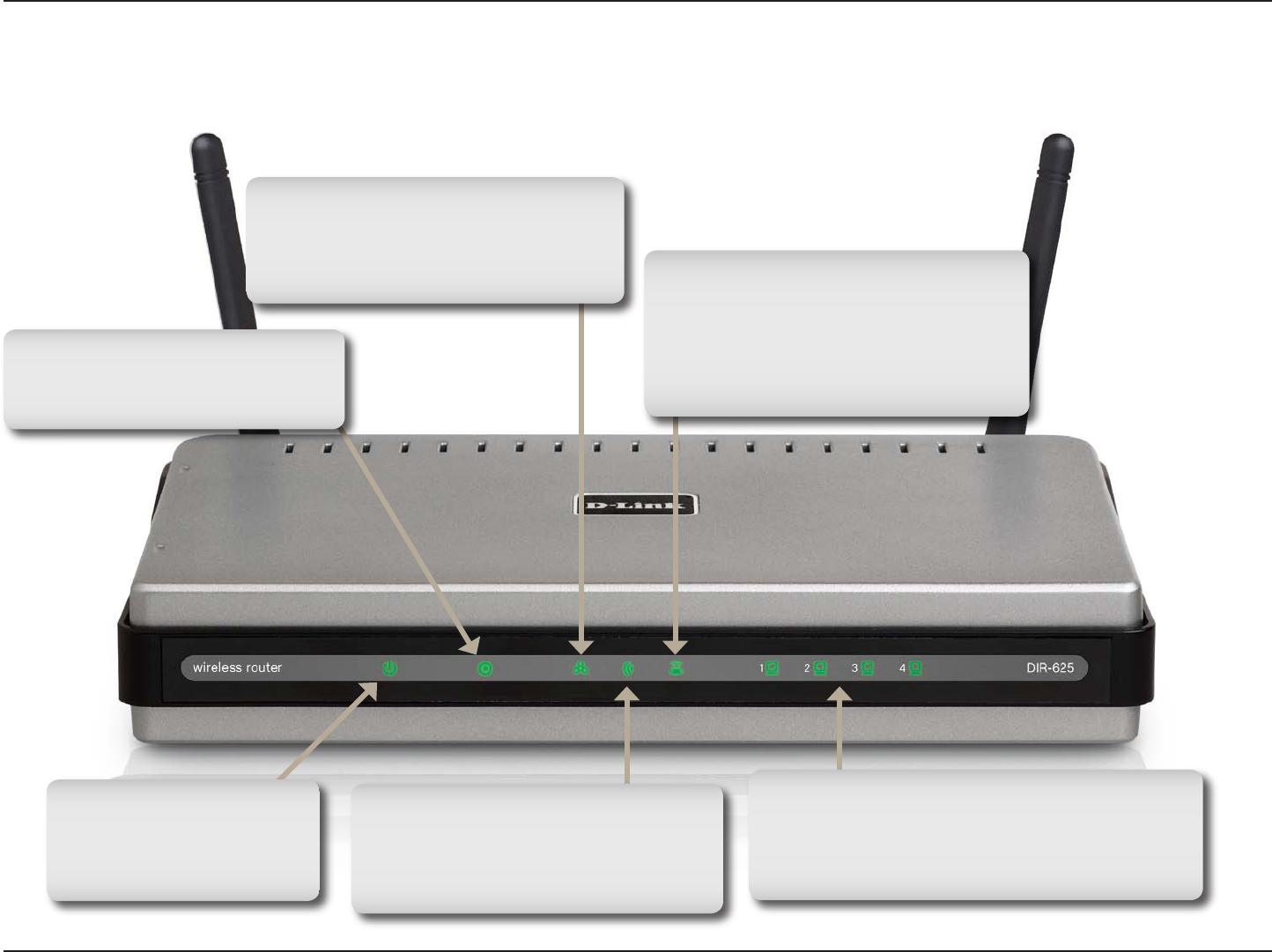
LEDs
WLAN LED
A solid light indicates that the wireless
segment is ready. This LED blinks
during wireless data transmission.
Status LED
A blinking light indicates that the
DIR-625 is ready.
Internet LED
A solid light indicates connection on
the Internet port. This LED blinks
during data transmission.
Power LED
A solid light indicates a
proper connection to the
power supply.
Local Network LEDs
A solid light indicates a connection to an
Ethernet-enabled computer on ports 1-4.
This LED blinks during data transmission.
WCN LED
Insert a USB flash drive with WCN
information. The LED will blink 3 times
if it successfully transfers the wireless
settings.

9D-Link DIR-625 User Manual
Section 2 - Installation
Before you Begin
Installation
This section will walk you through the installation process. Placement of the router is very important. Do not place the
router in an enclosed area such as a closet, cabinet, or in the attic or garage.
Please configure the router with the computer that was last connected directly to your modem. Also, you can only use
the Ethernet port on your modem. If you were using the USB connection before using the router, then you must turn off
your modem, disconnect the USB cable and connect an Ethernet cable to the Internet port on the router, and then turn
the modem back on. In some cases, you may need to call your ISP to change connection types (USB to Ethernet).
If you have DSL and are connecting via PPPoE, make sure you disable or uninstall any PPPoE software such as
WinPoet, Broadjump, or Enternet 300 from your computer or you will not be able to connect to the Internet.

10D-Link DIR-625 User Manual
Section 2 - Installation
Wireless Installation Considerations
The D-Link wireless router lets you access your network using a wireless connection from virtually anywhere within
the operating range of your wireless network. Keep in mind, however, that the number, thickness and location of walls,
ceilings, or other objects that the wireless signals must pass through, may limit the range. Typical ranges vary depending
on the types of materials and background RF (radio frequency) noise in your home or business. The key to maximizing
wireless range is to follow these basic guidelines:
1. Keep the number of walls and ceilings between the D-Link router and other network devices to a minimum
- each wall or ceiling can reduce your adapter’s range from 3-90 feet (1-30 meters.) Position your devices
so that the number of walls or ceilings is minimized.
2. Be aware of the direct line between network devices. A wall that is 1.5 feet thick (.5 meters), at a
45-degree angle appears to be almost 3 feet (1 meter) thick. At a 2-degree angle it looks over 42 feet
(14 meters) thick! Position devices so that the signal will travel straight through a wall or ceiling (instead
of at an angle) for better reception.
3. Building Materials make a difference. A solid metal door or aluminum studs may have a negative effect on
range. Try to position access points, wireless routers, and computers so that the signal passes through
drywall or open doorways. Materials and objects such as glass, steel, metal, walls with insulation, water
(fish tanks), mirrors, file cabinets, brick, and concrete will degrade your wireless signal.
4. Keep your product away (at least 3-6 feet or 1-2 meters) from electrical devices or appliances that
generate RF noise.
5. If you are using 2.4GHz cordless phones or X-10 (wireless products such as ceiling fans, lights, and
home security systems), your wireless connection may degrade dramatically or drop completely. Make
sure your 2.4GHz phone base is as far away from your wireless devices as possible. The base transmits
a signal even if the phone in not in use.

11D-Link DIR-625 User Manual
Section 2 - Installation
If you are connecting the router to a cable/DSL/satellite modem, please follow the steps below:
1. Place the router in an open and central location. Do not plug the power adapter into the router.
2. Turn the power off on your modem. If there is no on/off switch, then unplug the modem’s power adapter. Shut down
your computer.
3. Unplug the Ethernet cable (that connects your computer to your modem) from your computer and place it into the
Internet port on the router.
4. Plug an Ethernet cable into one of the four LAN ports on the router. Plug the other end into the Ethernet port on your
computer.
5. Turn on or plug in your modem. Wait for the modem to boot (about 30 seconds).
6. Plug the power adapter to the router and connect to an outlet or power strip. Wait about 30 seconds for the router
to boot.
7. Turn on your computer.
8. Verify the link lights on the router. The power light, Internet light, and the LAN light (the port that your computer is
plugged into) should be lit. If not, make sure your computer, modem, and router are powered on and verify the cable
connections are correct.
9. Skip to page 15 to configure your router.
Connect to Cable/DSL/Satellite Modem

12D-Link DIR-625 User Manual
Section 2 - Installation
If you are connecting the D-Link router to another router to use as a wireless access point and/or switch, you will have
to do the following before connecting the router to your network:
• Disable UPnP™
• Disable DHCP
• Change the LAN IP address to an available address on your network. The LAN ports on the router cannot
accept a DHCP address from your other router.
To connect to another router, please follow the steps below:
1. Plug the power into the router. Connect one of your computers to the router (LAN port) using an Ethernet cable.
Make sure your IP address on the computer is 192.168.0.xxx (where xxx is between 2 and 254). Please see the
Networking Basics section for more information. If you need to change the settings, write down your existing settings
before making any changes. In most cases, your computer should be set to receive an IP address automatically in
which case you will not have to do anything to your computer.
2. Open a web browser and enter http://192.168.0.1 and press Enter. When the login window appears, set the user
name to Admin and leave the password box empty. Click Log In to continue.
3. Click on Advanced and then click Advanced Network. Uncheck the Enable UPnP checkbox. Click Save Settings
to continue.
4. Click Setup and then click Network Settings. Uncheck the Enable DHCP Server server checkbox. Click Save
Settings to continue.
5. Under Router Settings, enter an available IP address and the subnet mask of your network. Click Save Settings to
save your settings. Use this new IP address to access the configuration utility of the router in the future. Close the
browser and change your computer’s IP settings back to the original values as in Step 1.
Connect to Another Router

13D-Link DIR-625 User Manual
Section 2 - Installation
6. Disconnect the Ethernet cable from the router and reconnect your computer to your network.
7. Connect an Ethernet cable in one of the LAN ports of the router and connect it to your other router. Do not plug
anything into the Internet port of the D-Link router.
8. You may now use the other 3 LAN ports to connect other Ethernet devices and computers. To configure your wireless
network, open a web browser and enter the IP address you assigned to the router. Refer to the Configuration and
Wireless Security sections for more information on setting up your wireless network.
14D-Link DIR-625 User Manual
Section 2 - Installation
Getting Started
The DIR-625 includes a Quick Router Setup Wizard CD. Follow the simple steps below to run the Setup Wizard to
guide you quickly through the installation process.
Insert the Quick Router Setup Wizard CD in the CD-ROM drive. The step-by-step instructions that follow are shown
in Windows XP. The steps and screens are similar for the other Windows operating systems.
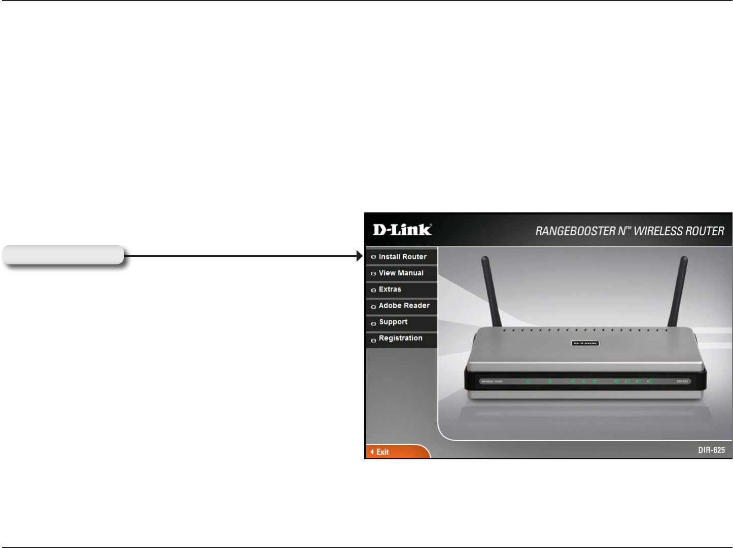
If the CD Autorun function does not automatically start on your computer.go to Start > Run. In the run box type
“D:\DIR625.exe” (where D: represents the drive letter of your CD-ROM drive).
When the autorun screen appears, click Install Router.
Click Install Router
Note: It is reccomended to write down the login password on the provided CD holder.
15D-Link DIR-625 User Manual
Section 3 - Configuration
Configuration
This section will show you how to configure your new D-Link wireless router using the web-based configuration
utility.
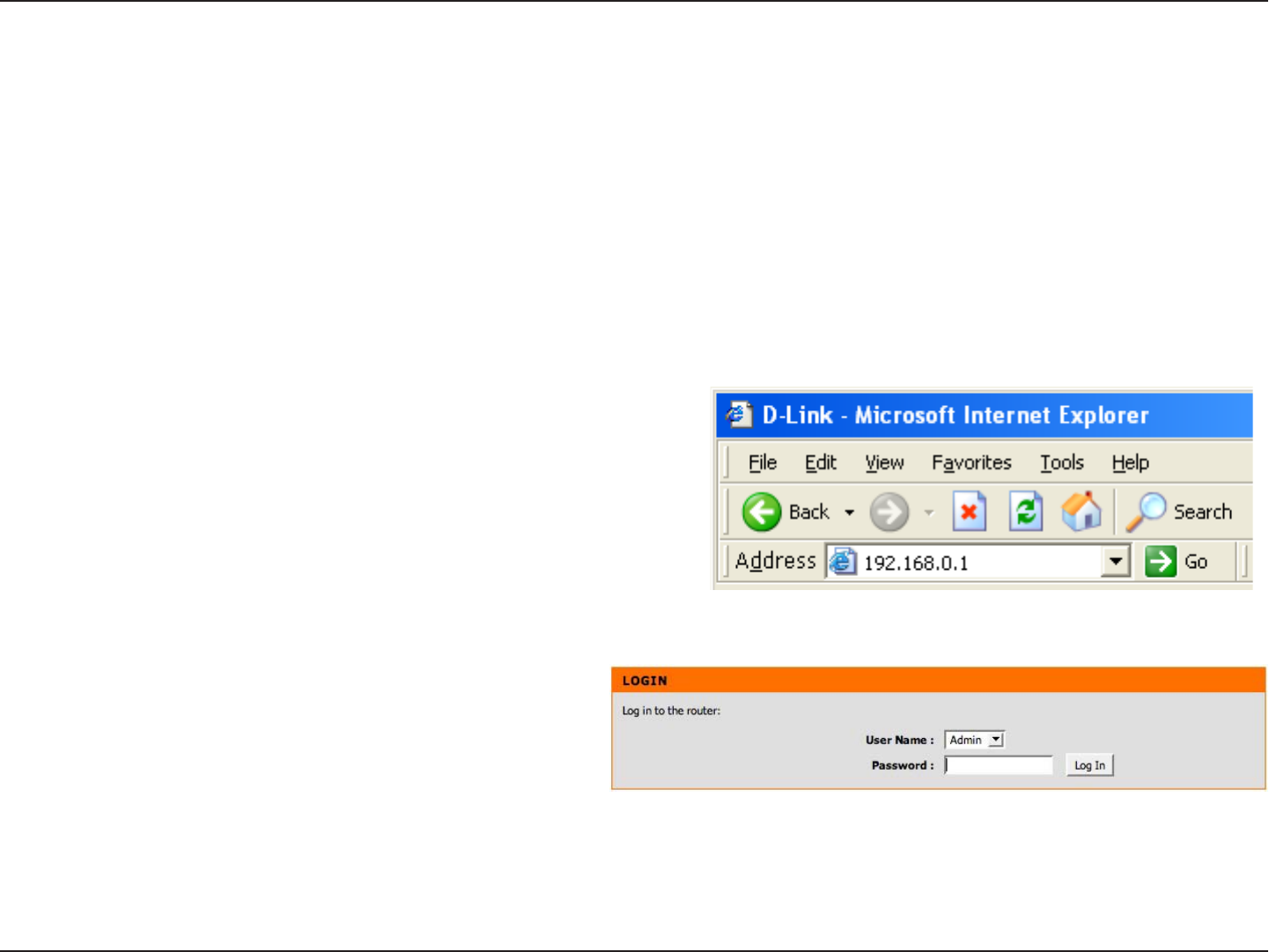
Web-based Configuration Utility
To access the configuration utility, open a web-browser
such as Internet Explorer and enter the IP address of
the router (192.168.0.1).
Select Admin from the drop-down menu and then enter
your password. Leave the password blank by default.
If you get a Page Cannot be Displayed error, please
refer to the Troubleshooting section for assistance.
16D-Link DIR-625 User Manual
Section 3 - Configuration
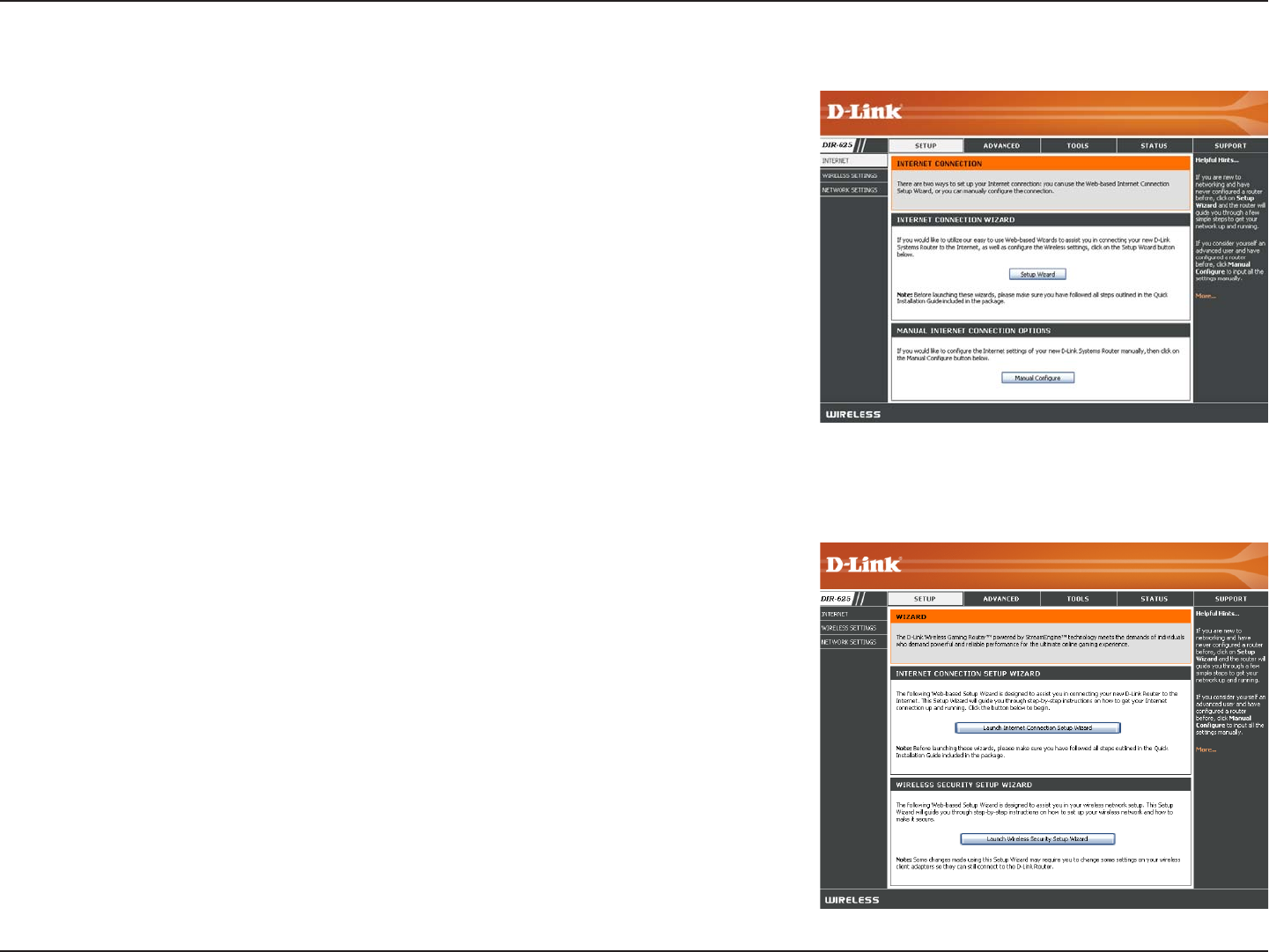
Setup Wizard
You may click Setup Wizard to quickly configure your router.
If you want to enter your settings without running the wizard, click
Manual Configuration and skip to page 20.
Click Launch Internet Connection Setup Wizard to begin.
If you want to configure your wireless settings, click Launch Wireless
Security Setup Wizard and skip to page 63.
17D-Link DIR-625 User Manual
Section 3 - Configuration
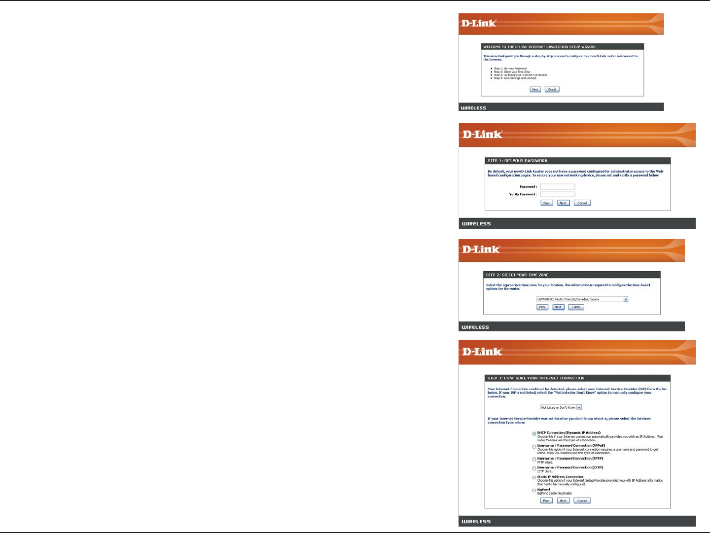
Click Next to continue.
Create a new password and then click Next to continue.
Select your time zone from the drop-down menu and then click Next
to continue.
Select the type of Internet connection you use and then click Next
to continue.
18D-Link DIR-625 User Manual
Section 3 - Configuration
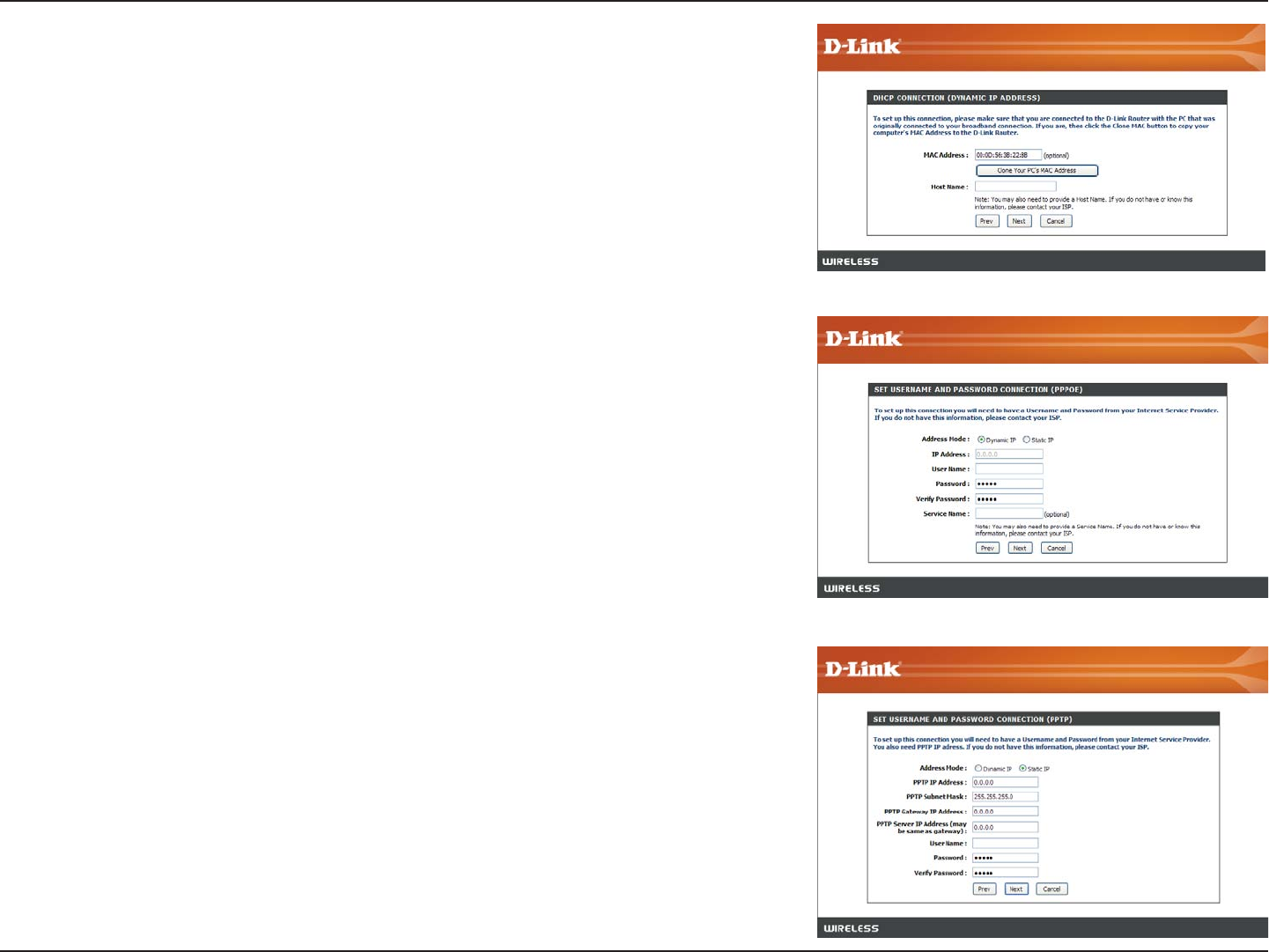
If you selected Dynamic, you may need to enter the MAC address of the
computer that was last connected directly to your modem. If you are currently
using that computer, click Clone Your PC’s MAC Address and then click
Next to continue.
The Host Name is optional but may be required by some ISPs. The default
host name is the device name of the Router and may be changed.
If you selected PPPoE, enter your PPPoE username and password. Click
Next to continue.
Select Static if your ISP assigned you the IP address, subnet mask, gateway,
and DNS server addresses.
Note: Make sure to remove your PPPoE software from your computer. The
software is no longer needed and will not work through a router.
If you selected PPTP, enter your PPTP username and password. Click Next
to continue.
19D-Link DIR-625 User Manual
Section 3 - Configuration
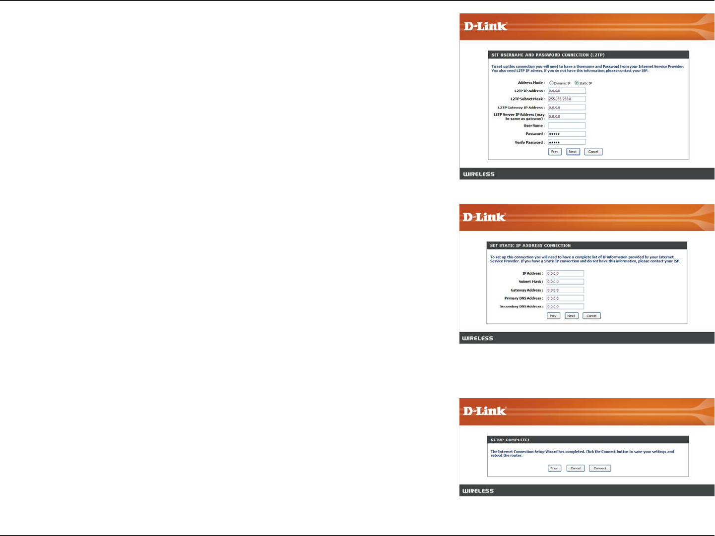
If you selected L2TP, enter your L2TP username and password. Click Next
to continue.
If you selected Static, enter your network settings supplied by your Internet
provider. Click Next to continue.
Click Connect to save your settings. Once the router is finished rebooting,
click Continue. Please allow 1-2 minutes to connect.
Close your browser window and reopen it to test your Internet connection.
It may take a few tries to initially connect to the Internet.
20D-Link DIR-625 User Manual
Section 3 - Configuration
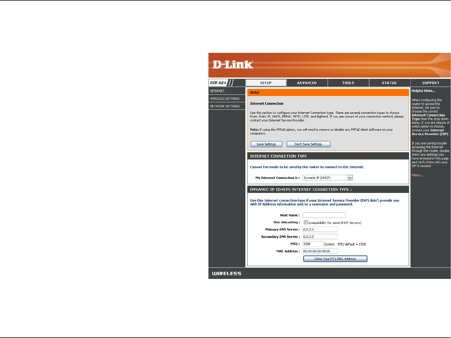
Select Dynamic IP (DHCP) to obtain IP Address
information automatically from your ISP. Select
this option if your ISP does not give you any IP
numbers to use. This option is commonly used
for Cable modem services.
The Host Name is optional but may be required
by some ISPs.
Check the box if you are having problems
obtaining an IP address from your ISP.
Enter the Primary DNS server IP address
assigned by your ISP.
Maximum Transmission Unit - you may need to
change the MTU for optimal performance with
your specific ISP. 1500 is the default MTU.
The default MAC Address is set to the Internet
port’s physical interface MAC address on the
Broadband Router. It is not recommended that
you change the default MAC address unless
required by your ISP. You can use the Clone
Your PC’s MAC Address button to replace
the Internet port’s MAC address with the MAC
address of your Ethernet card.
My Internet
Connection:
Host Name:
MAC Address:
Manual Configuration
Dynamic (Cable)
DNS Addresses:
MTU:
Use Unicasting:
21D-Link DIR-625 User Manual
Section 3 - Configuration
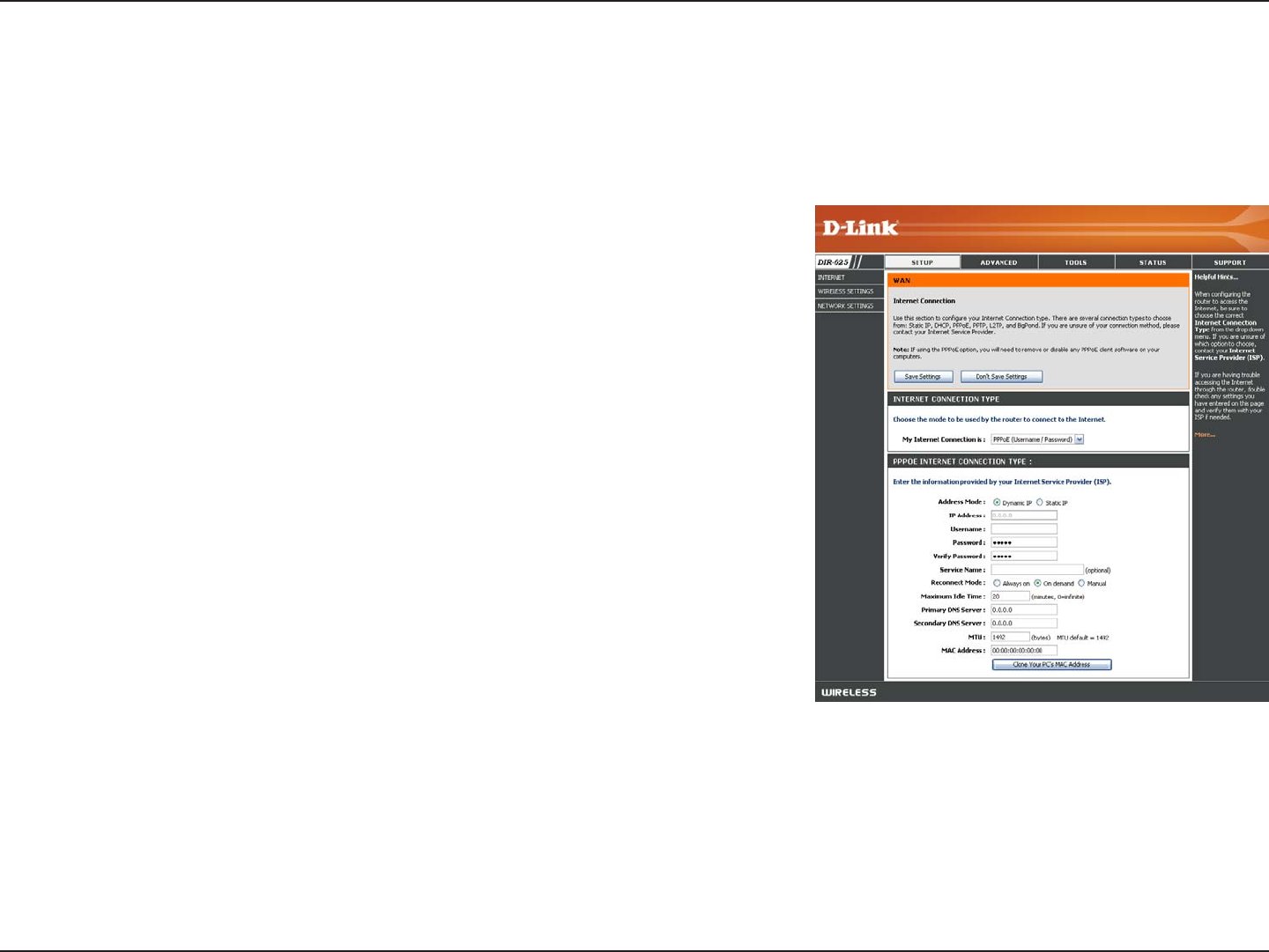
Select PPPoE (Username/Password) from the drop-down menu.
Select Static if your ISP assigned you the IP address, subnet mask,
gateway, and DNS server addresses. In most cases, select Dynamic.
Enter the IP address (Static PPPoE only).
Enter your PPPoE user name.
Enter your PPPoE password and then retype the password in the next
box.
Enter the ISP Service Name (optional).
Select either Always-on, On-Demand, or Manual.
Enter a maximum idle time during which the Internet connection is
maintained during inactivity. To disable this feature, enable Auto-
reconnect.
Enter the Primary and Secondary DNS Server Addresses (Static PPPoE only).
Maximum Transmission Unit - you may need to change the MTU for optimal performance with your specific ISP. 1492 is
the default MTU.
The default MAC Address is set to the Internet port’s physical interface MAC address on the Broadband Router. It is not
recommended that you change the default MAC address unless required by your ISP. You can use the Clone Your PC’s
MAC Address button to replace the Internet port’s MAC address with the MAC address of your Ethernet card.
My Internet
Connection:
Address Mode:
IP Address:
User Name:
Password:
Service Name:
Reconnection Mode:
Maximum Idle Time:
DNS Addresses:
MTU:
MAC Address:
Internet Setup
PPPoE (DSL)
Choose PPPoE (Point to Point Protocol over Ethernet) if your ISP uses a PPPoE connection. Your ISP will provide
you with a username and password. This option is typically used for DSL services. Make sure to remove your PPPoE
software from your computer. The software is no longer needed and will not work through a router.
22D-Link DIR-625 User Manual
Section 3 - Configuration
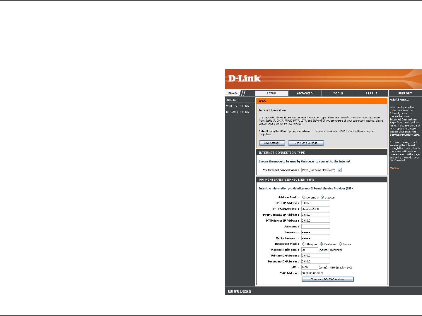
Select Static if your ISP assigned you the IP address,
subnet mask, gateway, and DNS server addresses. In most
cases, select Dynamic.
Enter the IP address (Static PPTP only).
Enter the Primary and Secondary DNS Server Addresses
(Static PPTP only).
Enter the Gateway IP Address provided by your ISP.
Enter the Server IP provided by your ISP (optional).
Enter your PPTP username.
Enter your PPTP password and then retype the password
in the next box.
Select either Always-on, On-Demand, or Manual.
Enter a maximum idle time during which the Internet
connection is maintained during inactivity. To disable this
feature, enable Auto-reconnect.
The DNS server information will be supplied by your ISP
(Internet Service Provider.)
Address Mode:
PPTP IP Address:
PPTP Subnet
Mask:
PPTP Gateway:
PPTP Server IP:
Internet Setup
PPTP
Choose PPTP (Point-to-Point-Tunneling Protocol ) if your ISP uses a PPTP connection. Your ISP will provide you with
a username and password. This option is typically used for DSL services.
Username:
Password:
Reconnect Mode:
Maximum Idle
Time:
DNS Servers:

23D-Link DIR-625 User Manual
Section 3 - Configuration
Maximum Transmission Unit - you may need to change the MTU for optimal performance with your specific ISP. 1400 is
the default MTU.
The default MAC Address is set to the Internet port’s physical interface MAC address on the Broadband Router. It is not
recommended that you change the default MAC address unless required by your ISP. You can use the Clone Your PC’s
MAC Address button to replace the Internet port’s MAC address with the MAC address of your Ethernet card.
MTU:
MAC Address:
24D-Link DIR-625 User Manual
Section 3 - Configuration
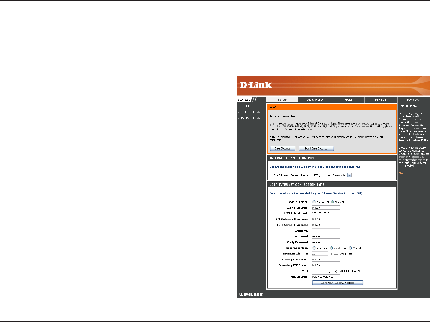
Select Static if your ISP assigned you the IP address,
subnet mask, gateway, and DNS server addresses. In
most cases, select Dynamic.
Enter the L2TP IP address supplied by your ISP (Static
only).
Enter the Subnet Mask supplied by your ISP (Static
only).
Enter the Gateway IP Address provided by your ISP.
Enter the Server IP provided by your ISP (optional).
Enter your L2TP username.
Enter your L2TP password and then retype the password
in the next box.
Select either Always-on, On-Demand, or Manual.
Enter a maximum idle time during which the Internet
connection is maintained during inactivity. To disable this
feature, enable Auto-reconnect.
Enter the Primary and Secondary DNS Server Addresses
(Static L2TP only).
Address Mode:
L2TP IP Address:
L2TP Subnet Mask:
L2TP Gateway:
L2TP Server IP:
Username:
Password:
Reconnect Mode:
Maximum Idle Time:
DNS Servers:
Internet Setup
L2TP
Choose L2TP (Layer 2 Tunneling Protocol) if your ISP uses a L2TP connection. Your ISP will provide you with a username
and password. This option is typically used for DSL services.

25D-Link DIR-625 User Manual
Section 3 - Configuration
MTU:
Clone MAC
Address:
Maximum Transmission Unit - you may need to change the MTU for optimal performance with your specific ISP. 1400 is the
default MTU.
The default MAC Address is set to the Internet port’s physical interface MAC address on the Broadband Router. It is not
recommended that you change the default MAC address unless required by your ISP. You can use the Clone Your PC’s
MAC Address button to replace the Internet port’s MAC address with the MAC address of your Ethernet card.
26D-Link DIR-625 User Manual
Section 3 - Configuration
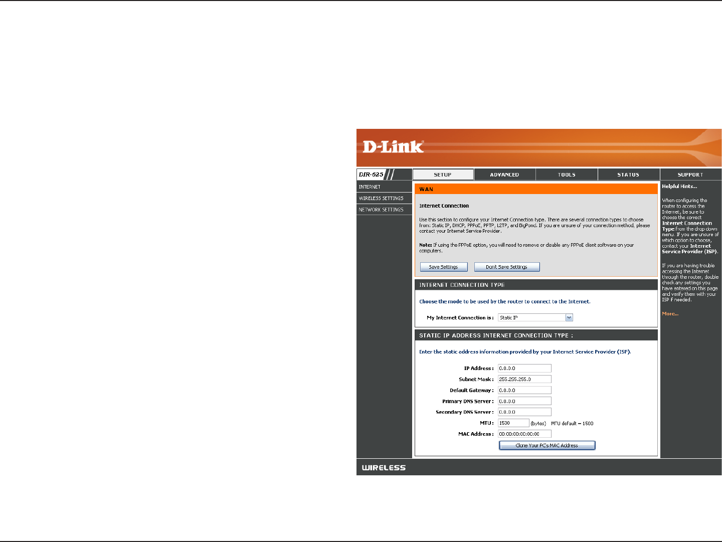
Enter the IP address assigned by your ISP.
Enter the Subnet Mask assigned by your ISP.
Enter the Gateway assigned by your ISP.
The DNS server information will be supplied by your
ISP (Internet Service Provider.)
Maximum Transmission Unit - you may need to
change the MTU for optimal performance with your
specific ISP. 1500 is the default MTU.
The default MAC Address is set to the Internet port’s
physical interface MAC address on the Broadband
Router. It is not recommended that you change the
default MAC address unless required by your ISP.
You can use the Clone Your PC’s MAC Address
button to replace the Internet port’s MAC address
with the MAC address of your Ethernet card.
IP Address:
Subnet Mask:
Default Gateway:
DNS Servers:
MTU:
MAC Address:
Internet Setup
Static (assigned by ISP)
Select Static IP Address if all the Internet port’s IP information is provided to you by your ISP. You will need to enter in the IP address,
subnet mask, gateway address, and DNS address(es) provided to you by your ISP. Each IP address entered in the fields must be in the
appropriate IP form, which are four octets separated by a dot (x.x.x.x). The Router will not accept the IP address if it is not in this format.
27D-Link DIR-625 User Manual
Section 3 - Configuration
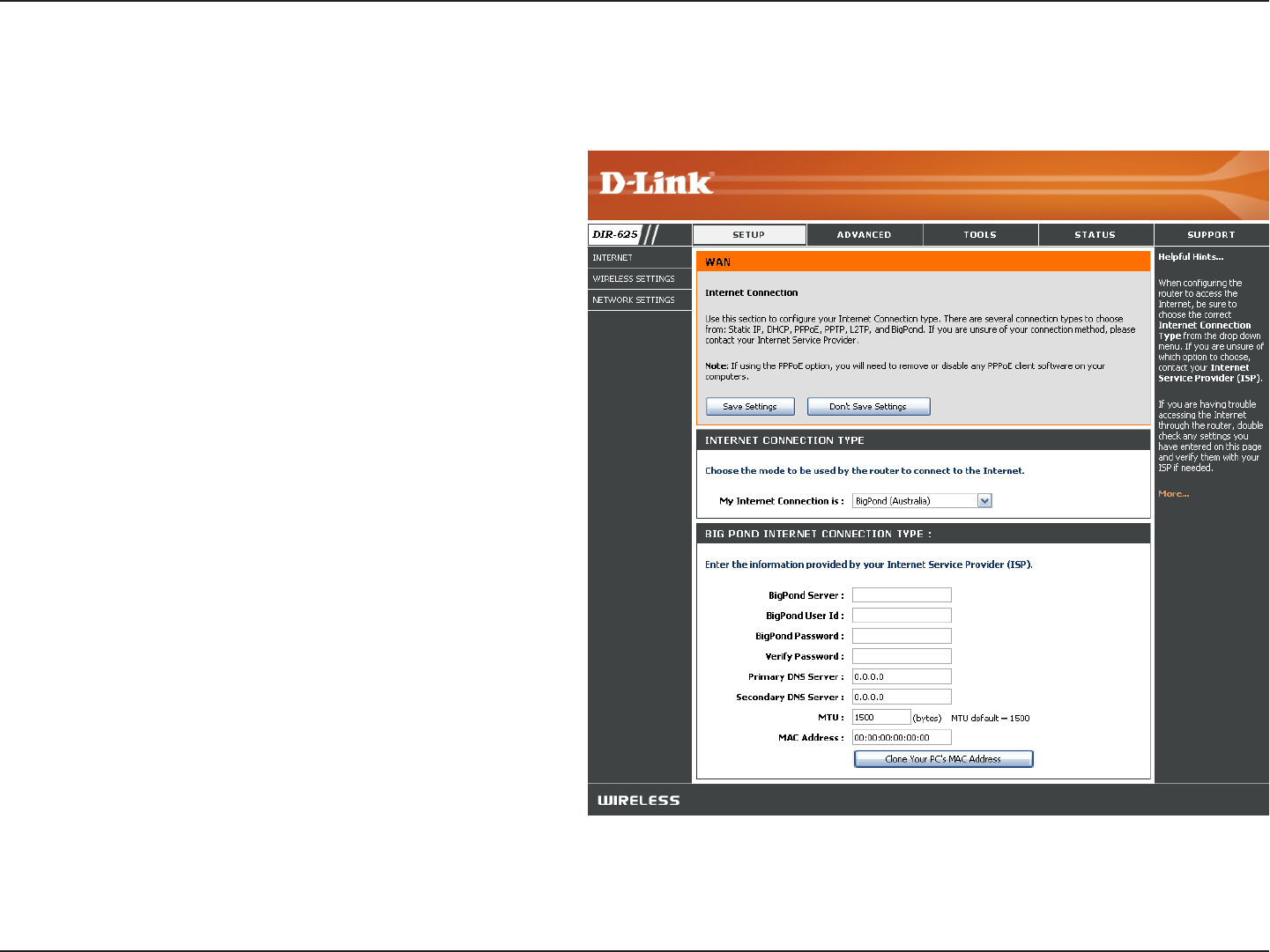
Enter the IP address of the login server.
Enter your BigPond username.
Enter your BigPond password and then retype
the password in the next box.
The DNS server information will be supplied
by your ISP (Internet Service Provider.)
Maximum Transmission Unit - you may need to
change the MTU for optimal performance with
your specific ISP. 1500 is the default MTU.
The default MAC Address is set to the
Internet’s physical interface MAC address on
the Broadband Router. It is not recommended
that you change the default MAC address
unless required by your ISP. You can use the
Clone Your PC’s MAC Address button to
replace the Internet port’s MAC address with
the MAC address of your Ethernet card.
BigPond Server:
BigPond Username:
BigPond Password:
DNS Servers:
MTU:
MAC Address:
Internet Setup
Big Pond
28D-Link DIR-625 User Manual
Section 3 - Configuration
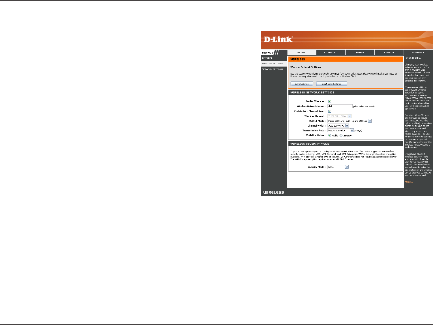
Check the box to enable the wireless function. If you do not
want to use wireless, uncheck the box to disable all the wireless
functions.
Service Set Identifier (SSID) is the name of your wireless network.
Create a name using up to 32 characters. The SSID is case-
sensitive.
The Auto Channel Scan setting can be selected to allow
the DIR-625 to choose the channel with the least amount of
interference.
Indicates the channel setting for the DIR-625. By default the
channel is set to 6. The Channel can be changed to fit the channel
setting for an existing wireless network or to customize the
wireless network. If you enable Auto Channel Scan, this option
will be greyed out.
Select one of the following:
802.11g Only - Select if all of your wireless clients are 802.11g.
Mixed 802.11g and 802.11b - Select if you are using both 802.11b and 802.11g wireless clients.
802.11b Only - Select if all of your wireless clients are 802.11b.
802.11n Only - Select only if all of your wireless clients are 802.11n.
Mixed 802.11n, 802.11b, and 802.11g - Select if you are using a mix of 802.11n, 11g, and 11b wireless clients.
Select the Channel Width:
Auto 20/40 - This is the default setting. Select if you are using both 802.11n and non-802.11n wireless devices.
20MHz - Select if you are not using any 802.11n wireless clients.
Select the transmit rate. It is strongly suggested to select Best (Auto) for best performance.
Enable Wireless:
Enable Auto
Channel Scan:
Wireless Settings
Wireless Network
Name:
Wireless Channel:
802.11 Mode:
Channel Width:
Transmission Rate:

29D-Link DIR-625 User Manual
Section 3 - Configuration
Select Invisible if you do not want the SSID of your wireless network to be broadcasted by the DIR-625. If Invisible is selected,
the SSID of the DIR-625 will not be seen by Site Survey utilities so your wireless clients will have to know the SSID of your
DIR-625 in order to connect to it.
Refer to page 61 for more information regarding wireless security.
Visibility Status:
Wireless Security:
30D-Link DIR-625 User Manual
Section 3 - Configuration
This section will allow you to change the local network settings of the router and to configure the DHCP settings.
Network Settings
Enter the IP address of the router. The default IP
address is 192.168.0.1.
If you change the IP address, once you click Apply,
you will need to enter the new IP address in your
browser to get back into the configuration utility.
Enter the Subnet Mask. The default subnet mask is
255.255.255.0.
Enter the Domain name (Optional).
Uncheck the box to transfer the DNS server
information from your ISP to your computers. If
checked, your computers will use the router for a
DNS server.
IP Address:
Subnet Mask:
Local Domain:
Enable DNS Relay:
31D-Link DIR-625 User Manual
Section 3 - Configuration
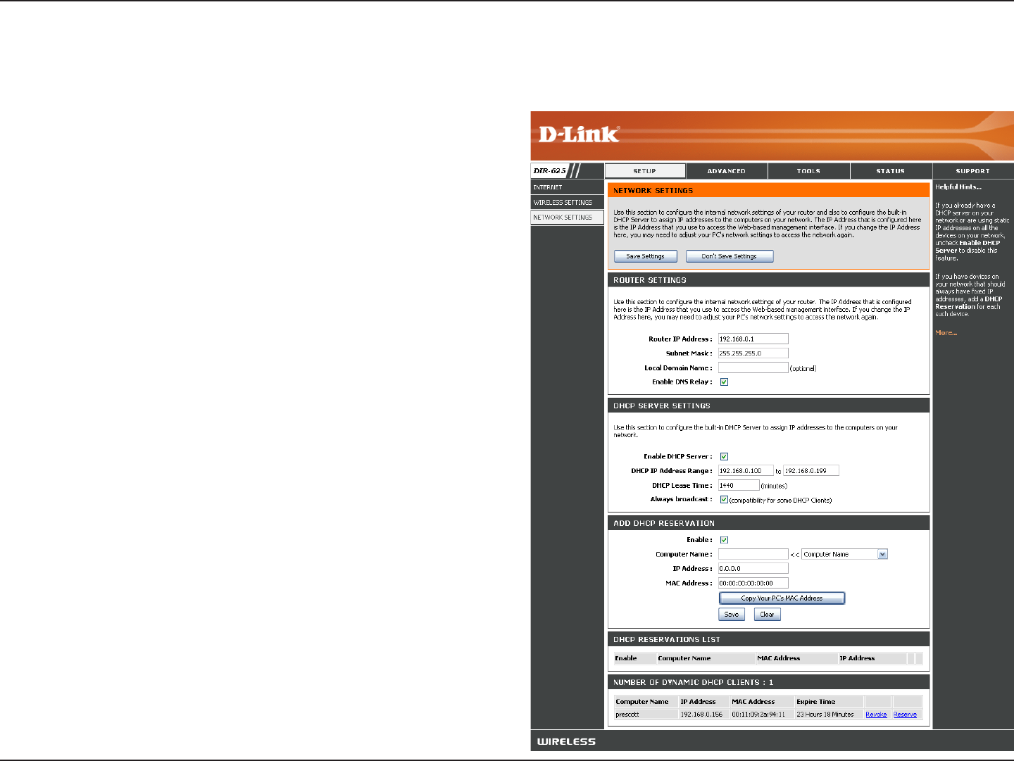
Check this box to enable the DHCP server on
your router. Uncheck to disable this function.
Enter the starting and ending IP addresses for
the DHCP server’s IP assignment.
Note: If you statically (manually) assign IP
addresses to your computers or devices, make
sure the IP addresses are outside of this range
or you may have an IP conflict.
The length of time for the IP address lease.
Enter the Lease time in minutes.
Refer to the next page for the DHCP Reservation
function.
Enable DHCP
Server:
DHCP IP Address
Range:
Lease Time:
Add DHCP
Reservation:
DHCP Server Settings
DHCP stands for Dynamic Host Control Protocol. The DIR-625 has a built-in DHCP server. The DHCP Server will
automatically assign an IP address to the computers on the LAN/private network. Be sure to set your computers to be
DHCP clients by setting their TCP/IP settings to “Obtain an IP Address Automatically.” When you turn your computers
on, they will automatically load the proper TCP/IP settings provided by the DIR-625. The DHCP Server will automatically
allocate an unused IP address from the IP address pool to the requesting computer. You must specify the starting and
ending address of the IP address pool.
32D-Link DIR-625 User Manual
Section 3 - Configuration
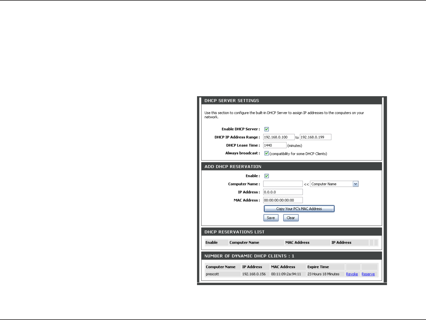
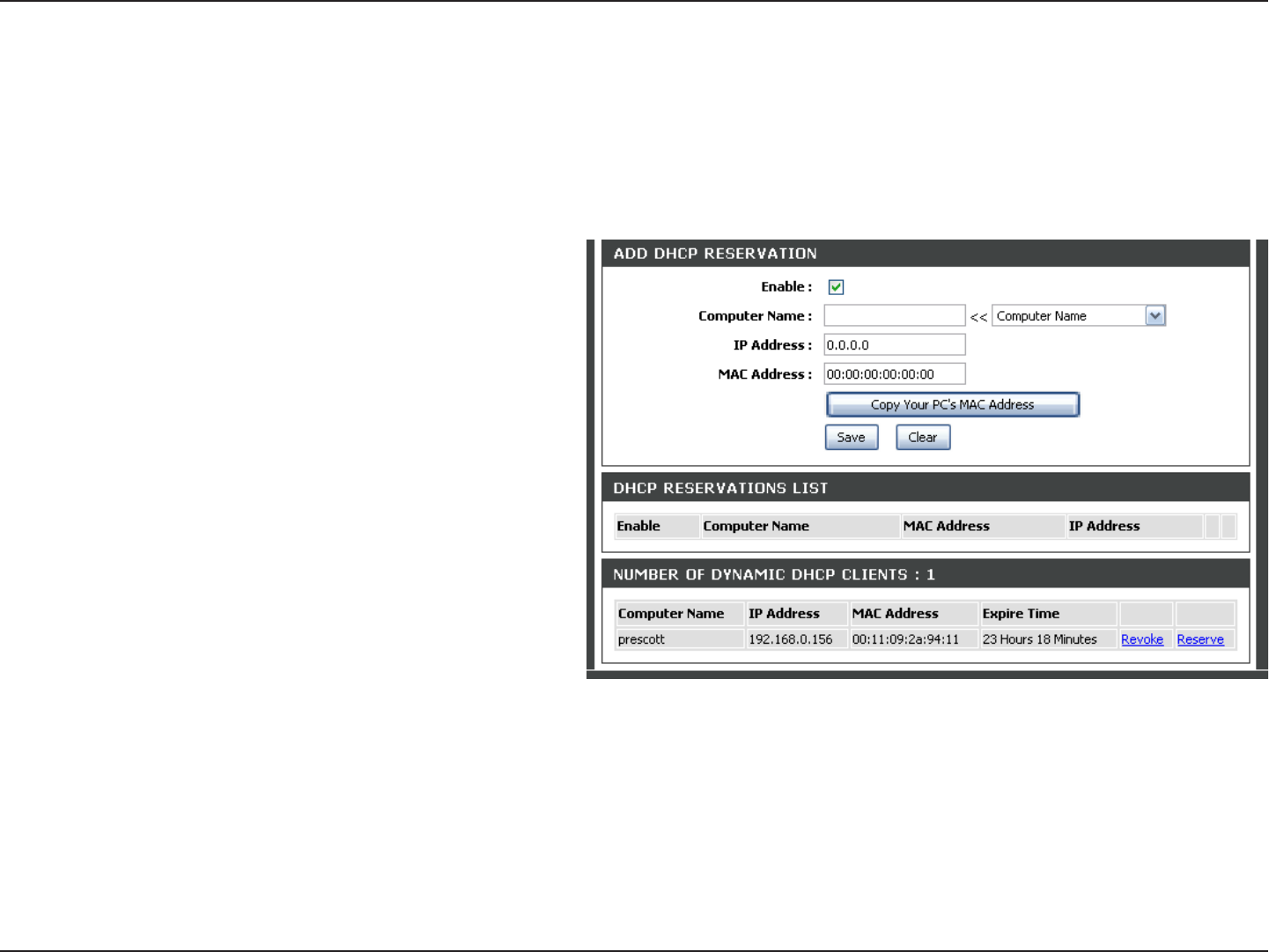
DHCP Reservation
If you want a computer or device to always have the same IP address assigned, you can create a DHCP reservation.
The router will assign the IP address only to that computer or device.
Note: This IP address must be within the DHCP IP Address Range.
Check this box to enable the reservation.
Enter the computer name or select from the drop-
down menu and click <<.
Enter the IP address you want to assign to the
computer or device. This IP Address must be
within the DHCP IP Address Range.
Enter the MAC address of the computer or
device.
If you want to assign an IP address to the
computer you are currently on, click this button
to populate the fields.
Click Save to save your entry. You must click
Save Settings at the top to activate your
reservations.
In this section you can see what LAN devices are currently leasing IP addresses.
Click Revoke to cancel the lease for a specific LAN device and free an entry in the lease table. Do this only if the device no
longer needs the leased IP address, because, for example, it has been removed from the network.
Enable:
Computer Name:
IP Address:
MAC Address:
Copy Your PC’s
MAC Address:
Save:
Number of
Dynamic DHCP
Clients:
Revoke:

33D-Link DIR-625 User Manual
Section 3 - Configuration
Reserve:
Note: The Revoke option will not disconnect a PC with a current network session from the network; you would need to use
MAC Address Filter to do that. Revoke will only free up a DHCP Address for the very next requester. If the previous
owner is still available, those two devices may both receive an IP Address Conflict error, or the second device may
still not receive an IP Address; in that case, you may still need to extend the “DHCP IP Address Range” to address
the issue, it is located in the DHCP Server section.
The Reserve option converts this dynamic IP allocation into a DHCP Reservation and adds the corresponding entry to the
DHCP Reservations List.

34D-Link DIR-625 User Manual
Section 3 - Configuration
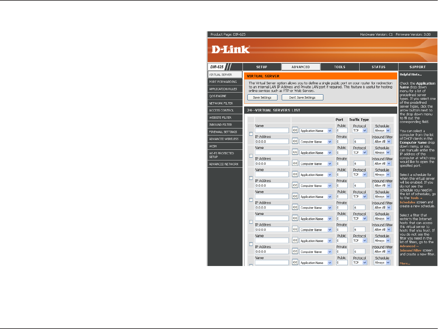
The DIR-625 can be configured as a virtual server so that remote users accessing Web or FTP services via the public
IP address can be automatically redirected to local servers in the LAN (Local Area Network).
The DIR-625 firewall feature filters out unrecognized packets to protect your LAN network so all computers networked
with the DIR-625 are invisible to the outside world. If you wish, you can make some of the LAN computers accessible
from the Internet by enabling Virtual Server. Depending on the requested service, the DIR-625 redirects the external
service request to the appropriate server within the LAN network.
The DIR-625 is also capable of port-redirection meaning incoming traffic to a particular port may be redirected to a
different port on the server computer.
Each virtual service that is created will be listed at the bottom of the screen in the Virtual Servers List. There are
pre-defined virtual services already in the table. You may use them by enabling them and assigning the server IP to
use that particular virtual service.
For a list of ports for common applications, please visit http://support.dlink.com/faq/view.asp?prod_id=1191.
Virtual Server
35D-Link DIR-625 User Manual
Section 3 - Configuration
This will allow you to open a single port. If you would like to open a range of ports, refer to page 35.
Enter a name for the rule or select an application
from the drop-down menu. Select an application
and click << to populate the fields.
Enter the IP address of the computer on your
local network that you want to allow the incoming
service to. If your computer is receiving an IP
address automatically from the router (DHCP),
you computer will be listed in the “Computer
Name” drop-down menu. Select your computer
and click <<.
Enter the port that you want to open next to Private
Port and Public Port. The private and public ports
are usually the same. The public port is the port
seen from the Internet side, and the private port
is the port being used by the application on the
computer within your local network.
Select TCP, UDP, or Both from the drop-down
menu.
Select Allow All (most common) or a created
Inbound filter. You may create your own inbound
filters in the Advanced > Inbound Filter page.
The schedule of time when the Virtual Server
Rule will be enabled. The schedule may be set to
Always, which will allow the particular service to
always be enabled. You can create your own times
in the Tools > Schedules section.
Name:
IP Address:
Private Port/
Public Port:
Protocol Type:
Inbound Filter:
Schedule:
36D-Link DIR-625 User Manual
Section 3 - Configuration
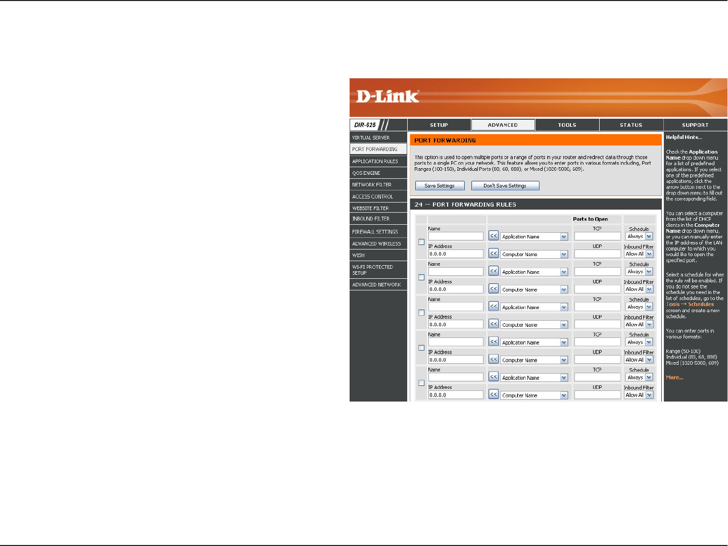
This will allow you to open a single port or a range of ports.
Port Forwarding
Enter a name for the rule or select an application
from the drop-down menu. Select an application
and click << to populate the fields.
Enter the IP address of the computer on your local
network that you want to allow the incoming service
to. If your computer is receiving an IP address
automatically from the router (DHCP), you computer
will be listed in the “Computer Name” drop-down
menu. Select your computer and click <<.
Enter the TCP and/or UDP port or ports that you
want to open. You can enter a single port or a range
of ports. Seperate ports with a common.
Example: 24,1009,3000-4000
Select Allow All (most common) or a created
Inbound filter. You may create your own inbound
filters in the Advanced > Inbound Filter page.
The schedule of time when the Virtual Server Rule
will be enabled. The schedule may be set to Always,
which will allow the particular service to always
be enabled. You can create your own times in the
Tools > Schedules section.
Name:
IP Address:
TCP/UDP:
Inbound Filter:
Schedule:
37D-Link DIR-625 User Manual
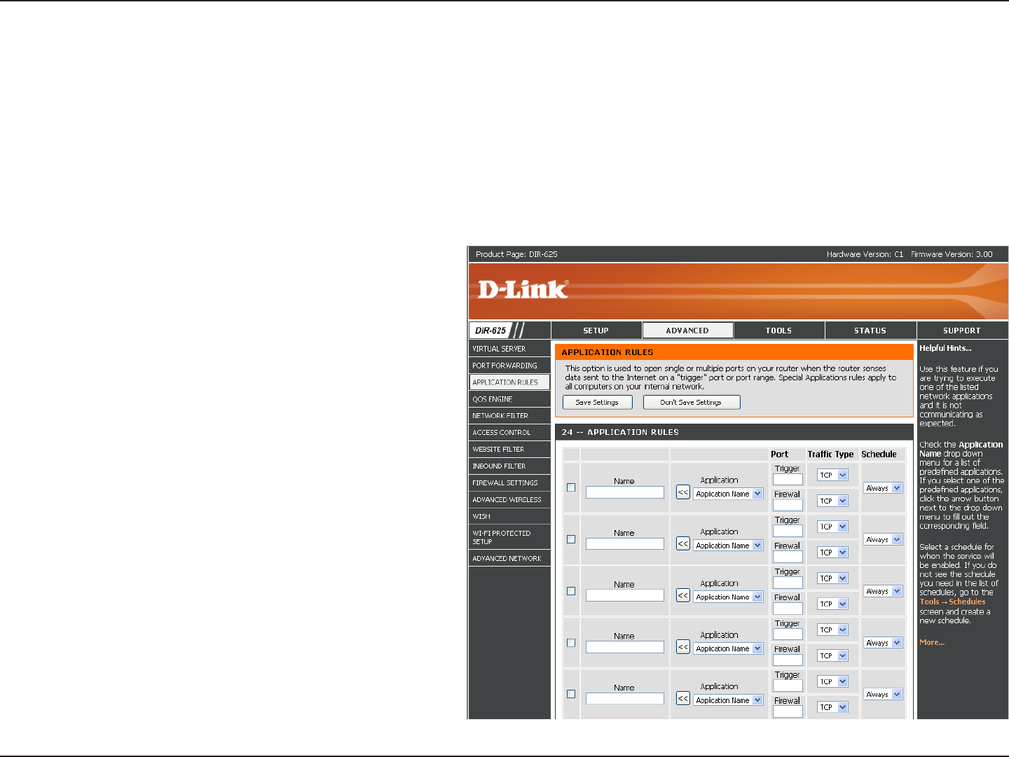
Section 3 - Configuration
Enter a name for the rule. You may select a
pre-defined application from the drop-down
menu and click <<.
This is the port used to trigger the application. It
can be either a single port or a range of ports.
Select the protocol of the trigger port (TCP,
UDP, or Both).
This is the port number on the Internet side
that will be used to access the application. You
may define a single port or a range of ports.
You can use a comma to add multiple ports or
port ranges.
Select the protocol of the firewall port (TCP,
UDP, or Both).
The schedule of time when the Application Rule
will be enabled. The schedule may be set to
Always, which will allow the particular service
to always be enabled. You can create your own
times in the Tools > Schedules section.
Name:
Trigger:
Traffic Type:
Firewall:
Traffic Type:
Schedule:
Application Rules
Some applications require multiple connections, such as Internet gaming, video conferencing, Internet telephony and
others. These applications have difficulties working through NAT (Network Address Translation). Special Applications
makes some of these applications work with the DIR-625. If you need to run applications that require multiple connections,
specify the port normally associated with an application in the “Trigger Port” field, select the protocol type as TCP or
UDP, then enter the firewall (public) ports associated with the trigger port to open them for inbound traffic.
The DIR-625 provides some predefined applications in the table on the bottom of the web page. Select the application
you want to use and enable it.
38D-Link DIR-625 User Manual
Section 3 - Configuration
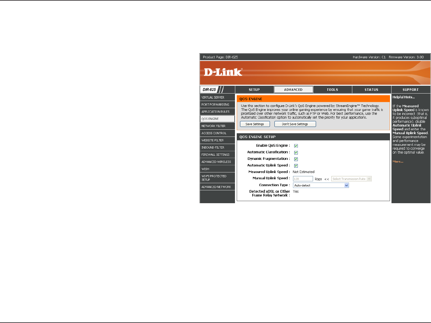
QoS Engine
This option is disabled by default. Enable this
option for better performance and experience with
online games and other interactive applications,
such as VoIP.
This option should be enabled when you have a
slow Internet uplink. It helps to reduce the impact
that large low priority network packets can have
on more urgent ones.
This option is enabled by default when the QoS
Engine option is enabled. This option will allow
your router to automatically determine the uplink
speed of your Internet connection.
This displays the detected uplink speed.
The speed at which data can be transferred from the router to your ISP. This is determined by your ISP. ISP’s often speed as
a download/upload pair. For example, 1.5Mbits/284Kbits. Using this example, you would enter 284. Alternatively you can test
your uplink speed with a service such as www.dslreports.com.
By default, the router automatically determines whether the underlying connection is an xDSL/Frame-relay network or some
other connection type (such as cable modem or Ethernet), and it displays the result as Detected xDSL or Frame Relay Network.
If you have an unusual network connection in which you are actually connected via xDSL but for which you configure either
“Static” or “DHCP” in the Internet settings, setting this option to xDSL or Other Frame Relay Network ensures that the router
will recognize that it needs to shape traffic slightly differently in order to give the best performance. Choosing xDSL or Other
Frame Relay Network causes the measured uplink speed to be reported slightly lower than before on such connections, but
gives much better results.
When Connection Type is set to automatic, the automatically detected connection type is displayed here.
Enable
StreamEngine:
Dynamic
Fragmentation:
Automatic Uplink
Speed:
Measured Uplink
Speed:
Manual Uplink
Speed:
Connection Type:
Detected xDSL:
The QoS Engine option helps improve your network gaming performance by prioritizing applications. By default the
QoS Engine settings are disabled and application priority is not classified automatically.
39D-Link DIR-625 User Manual
Section 3 - Configuration
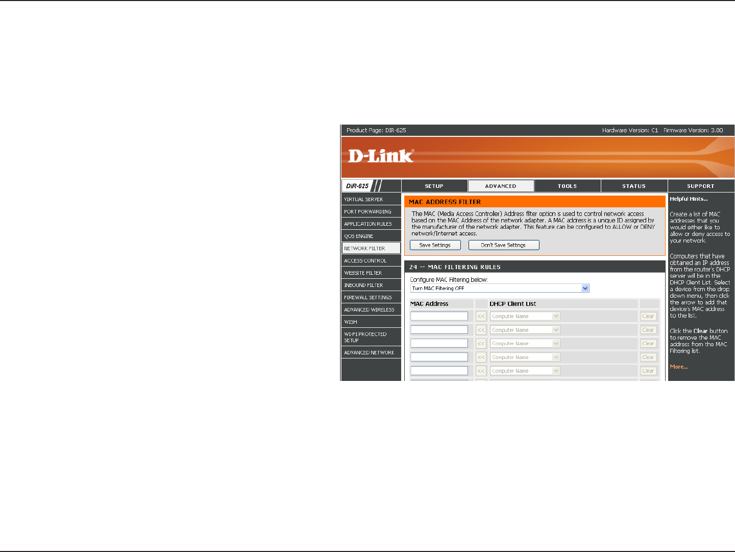
Network Filters
Select Turn MAC Filtering Off, allow MAC
addresses listed below, or deny MAC addresses
listed below from the drop-down menu.
Enter the MAC address you would like to filter.
To find the MAC address on a computer, please
refer to the Networking Basics section in this
manual.
Select a DHCP client from the drop-down menu
and click << to copy that MAC Address.
Configure MAC
Filtering:
MAC Address:
DHCP Client:
Use MAC (Media Access Control) Filters to allow or deny LAN (Local Area Network) computers by their MAC addresses
from accessing the Network. You can either manually add a MAC address or select the MAC address from the list of
clients that are currently connected to the Broadband Router.
40D-Link DIR-625 User Manual
Section 3 - Configuration
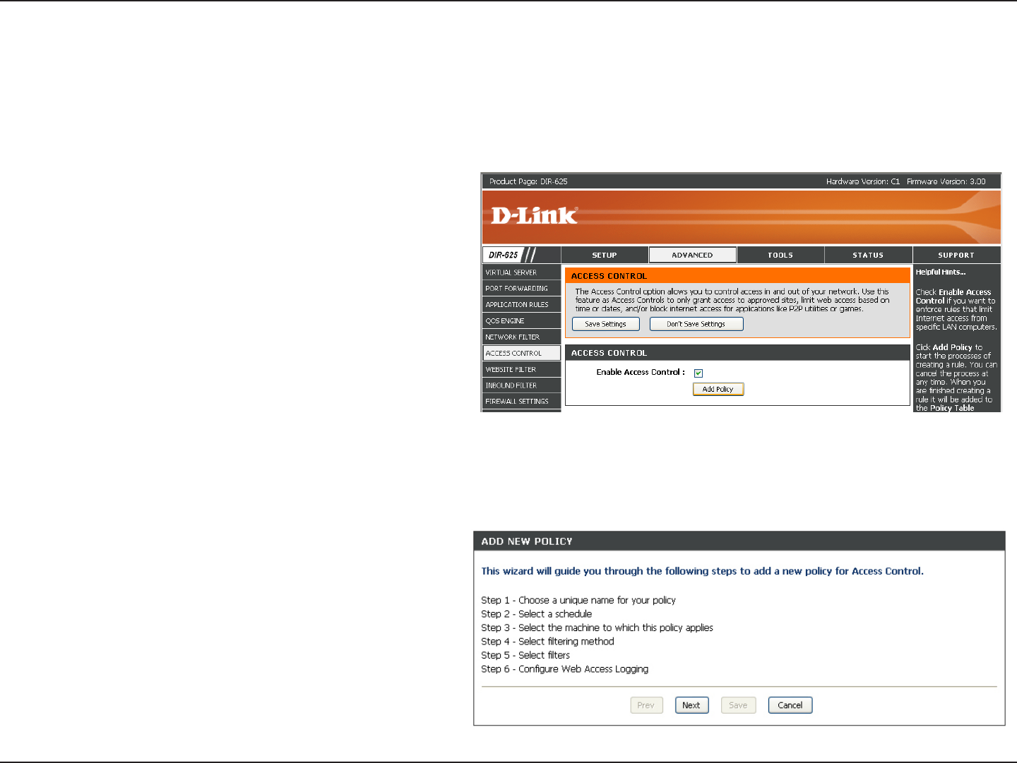
Access Control
Check the Enable Access Control check box
and click the Add Policy button to start the
Access Control Wizard.
Add Policy:
The Access Control section allows you to control access in and out of your network. Use this feature as Parental Controls
to only grant access to approved sites, limit web access based on time or dates, and/or block access from applications
like P2P utilities or games.
Click Next to continue with the wizard.
Access Control Wizard
41D-Link DIR-625 User Manual
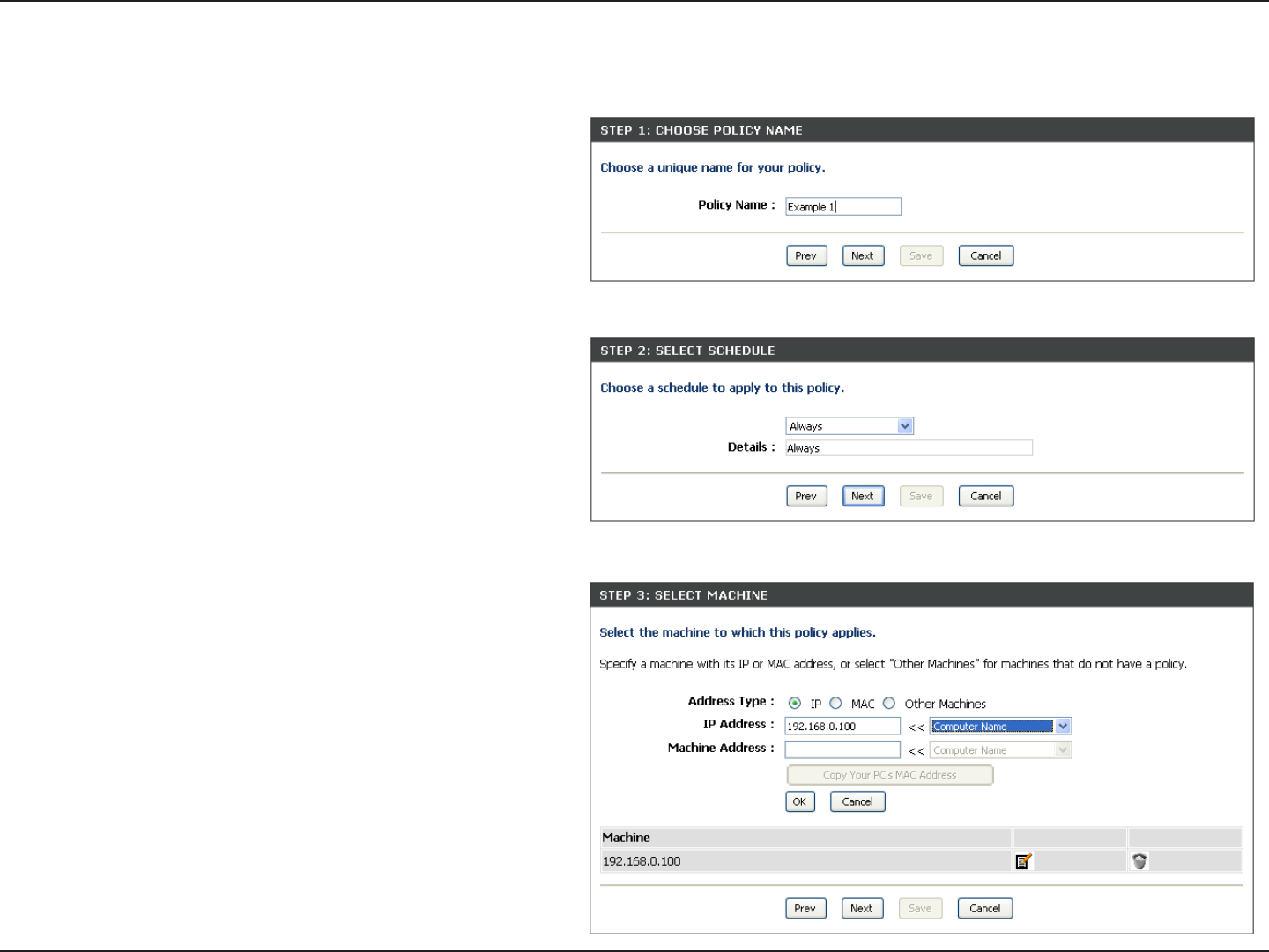
Section 3 - Configuration
Enter a name for the policy and then click Next to continue.
Access Control Wizard (continued)
Select a schedule (I.E. Always) from the drop-down menu
and then click Next to continue.
Enter the following information and then click Next to
continue.
• Address Type - Select IP address, MAC address, or
Other Machines.
• IP Address - Enter the IP address of the computer
you want to apply the rule to.
42D-Link DIR-625 User Manual
Section 3 - Configuration
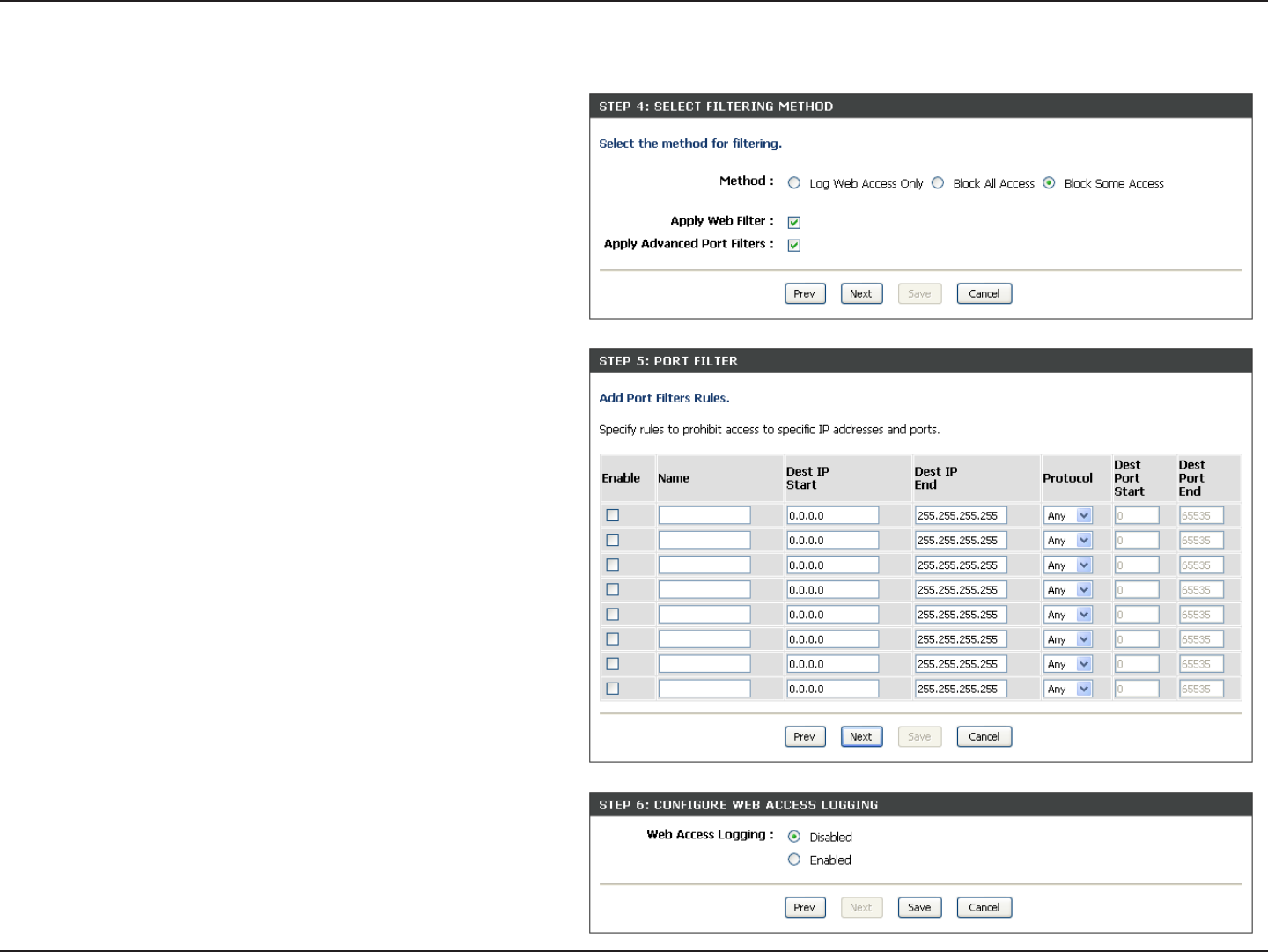
Select the filtering method and then click Next to continue.
Access Control Wizard (continued)
Enter the rule:
Enable - Check to enable the rule.
Name - Enter a name for your rule.
Dest IP Start - Enter the starting IP address.
Dest IP End - Enter the ending IP address.
Protocol - Select the protocol.
Dest Port Start - Enter the starting port number.
Dest Port End - Enter the ending port number.
To enable web logging, click Enable.
Click Save to save the access control rule.
43D-Link DIR-625 User Manual
Section 3 - Configuration
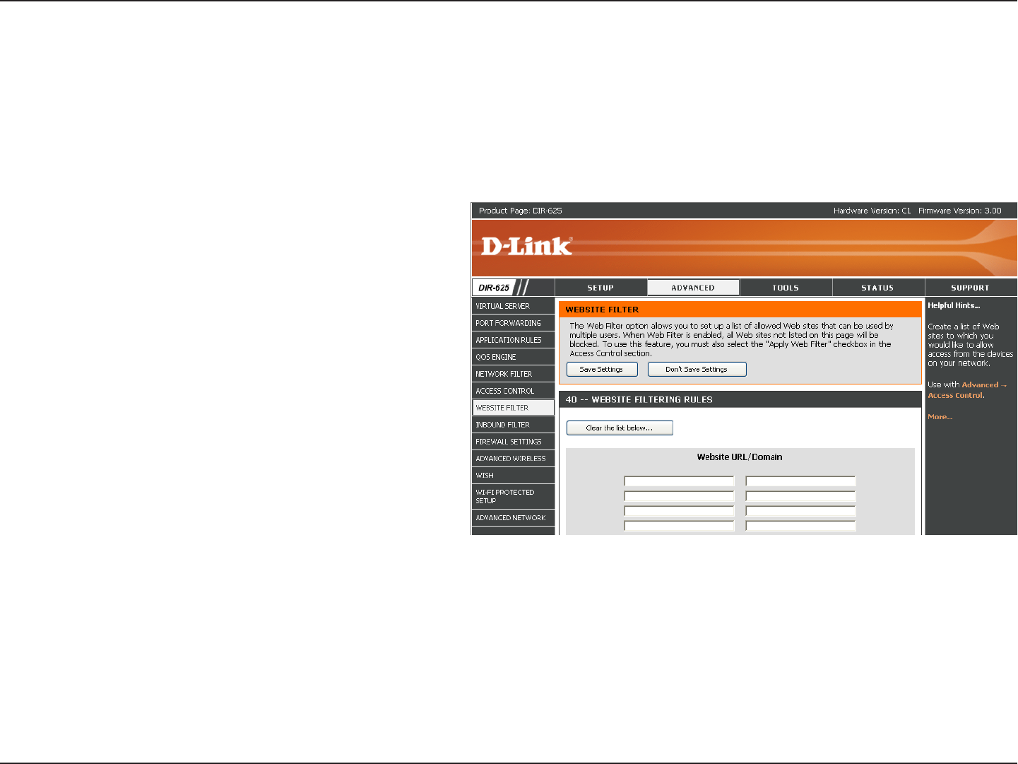
Enter the keywords or URLs that you want to
block (or allow). Any URL with the keyword in it
will be blocked.
Website URL/
Domain:
Website Filters are used to deny LAN computers from accessing specific web sites by the URL or domain. A URL is a
specially formatted text string that defines a location on the Internet. If any part of the URL contains the blocked word,
the site will not be accessible and the web page will not display. To use this feature, enter the text string to be blocked
and click Save Settings. The text to be blocked will appear in the list. To delete the text, click Clear the List Below.
Website Filters
44D-Link DIR-625 User Manual
Section 3 - Configuration
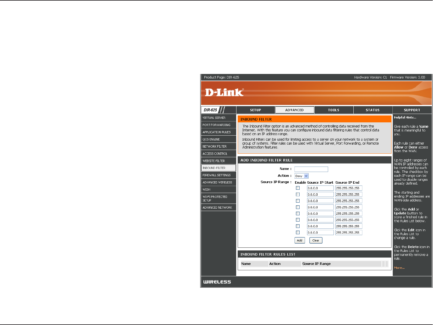
Enter a name for the inbound filter rule.
Select Allow or Deny.
Check to enable rule.
Enter the starting IP address. Enter 0.0.0.0 if
you do not want to specify an IP range.
Enter the ending IP address. Enter
255.255.255.255 if you do not want to specify
and IP range.
Click the Save button to apply your settings.
You must click Save Settings at the top to save
the settings.
This section will list any rules that are created.
You may click the Edit icon to change the
settings or enable/disable the rule, or click the
Delete icon to remove the rule.
Name:
Action:
Enable:
Source IP Start:
Source IP End:
Save:
Inbound Filter
Rules List:
The Inbound Filter option is an advanced method of controlling data received from the Internet. With this feature you
can configure inbound data filtering rules that control data based on an IP address range. Inbound Filters can be used
with Virtual Server, Port Forwarding, or Remote Administration features.
Inbound Filters
45D-Link DIR-625 User Manual
Section 3 - Configuration
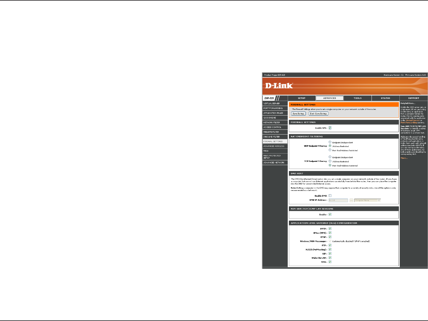
SPI (Stateful Packet Inspection, also known as dynamic packet
filtering) helps to prevent cyber attacks by tracking more state per
session. It validates that the traffic passing through the session
conforms to the protocol.
Select one of the following for TCP and UDP ports:
Endpoint Independent - Any incoming traffic sent to an open port
will be forwarded to the application that opened the port. The port
will close if idle for 5 minutes.
Address Restricted - Incoming traffic must match the IP address
of the outgoing connection.
Address + Port Restriction - Incoming traffic must match the IP
address and port of the outgoing connection.
If an application has trouble working from behind the router, you
can expose one computer to the Internet and run the application
on that computer.
Note: Placing a computer in the DMZ may expose that computer to
a variety of security risks. Use of this option is only recommended
as a last resort.
Specify the IP address of the computer on the LAN that you want to have unrestricted Internet communication. If this computer
obtains it’s IP address automatically using DHCP, be sure to make a static reservation on the Basic > DHCP page so that
the IP address of the DMZ machine does not change.
Enable SPI:
NAT Endpoint
Filtering:
Enable DMZ Host:
IP Address:
Firewall Settings
A firewall protects your network from the outside world. The D-Link DIR-625 offers a firewall type functionality. The SPI
feature helps prevent cyber attacks. Sometimes you may want a computer exposed to the outside world for certain
types of applications. If you choose to expose a computer, you can enable DMZ. DMZ is short for Demilitarized Zone.
This option will expose the chosen computer completely to the outside world.

46D-Link DIR-625 User Manual
Section 3 - Configuration
VPN Passthrough
RTSP
H.323
SIP (VoIP)
MMS
Application Level Gateway (ALG) Configuration
Here you can enable or disable ALG’s. Some protocols and applications require special handling of the IP payload to
make them work with network address translation (NAT). Each ALG provides special handling for a specific protocol
or application. A number of ALGs for common applications are enabled by default.
Allows multiple machines on the LAN to connect to their corporate network using PPTP protocol.
Allows multiple VPN clients to connect to their corporate network using IPSec. Some VPN clients support traversal of IPSec
through NAT. This ALG may interfere with the operation of such VPN clients. If you are having trouble connecting with your
corporate network, try turning this ALG off. Please check with the system adminstrator of your corporate network whether
your VPN client supports NAT traversal.
Allows applications that use Real Time Streaming Protocol to receive streaming media from the internet. QuickTime and
Real Player are some of the common applications using this protocol.
Allows all of the Windows/MSN Messenger functions to work properly through the router.
Allows FTP clients and servers to transfer data across NAT. Refer to the Advanced > Virtual Server page if you want to
host an FTP server.
Allows Microsoft NetMeeting clients to communicate across NAT. Note that if you want your buddies to call you, you should
also set up a virtual server for NetMeeting. Refer to the Advanced > Virtual Server page for information on how to set up
a virtual server.
Allows devices and applications using VoIP (Voice over IP) to communicate across NAT. Some VoIP applications and devices
have the ability to discover NAT devices and work around them. This ALG may interfere with the operation of such devices.
If you are having trouble making VoIP calls, try turning this ALG off.
Allows Ethernet network adapters with Wake-On-LAN (WOL) to function.
Allows Windows Media Player, using MMS protocol, to receive streaming media from the Internet.
PPTP:
IPSEC (VPN):
RTSP:
MSN Messenger:
FTP:
H.323
(Netmeeting):
SIP:
Wake-On-LAN:
MMS:
47D-Link DIR-625 User Manual
Section 3 - Configuration
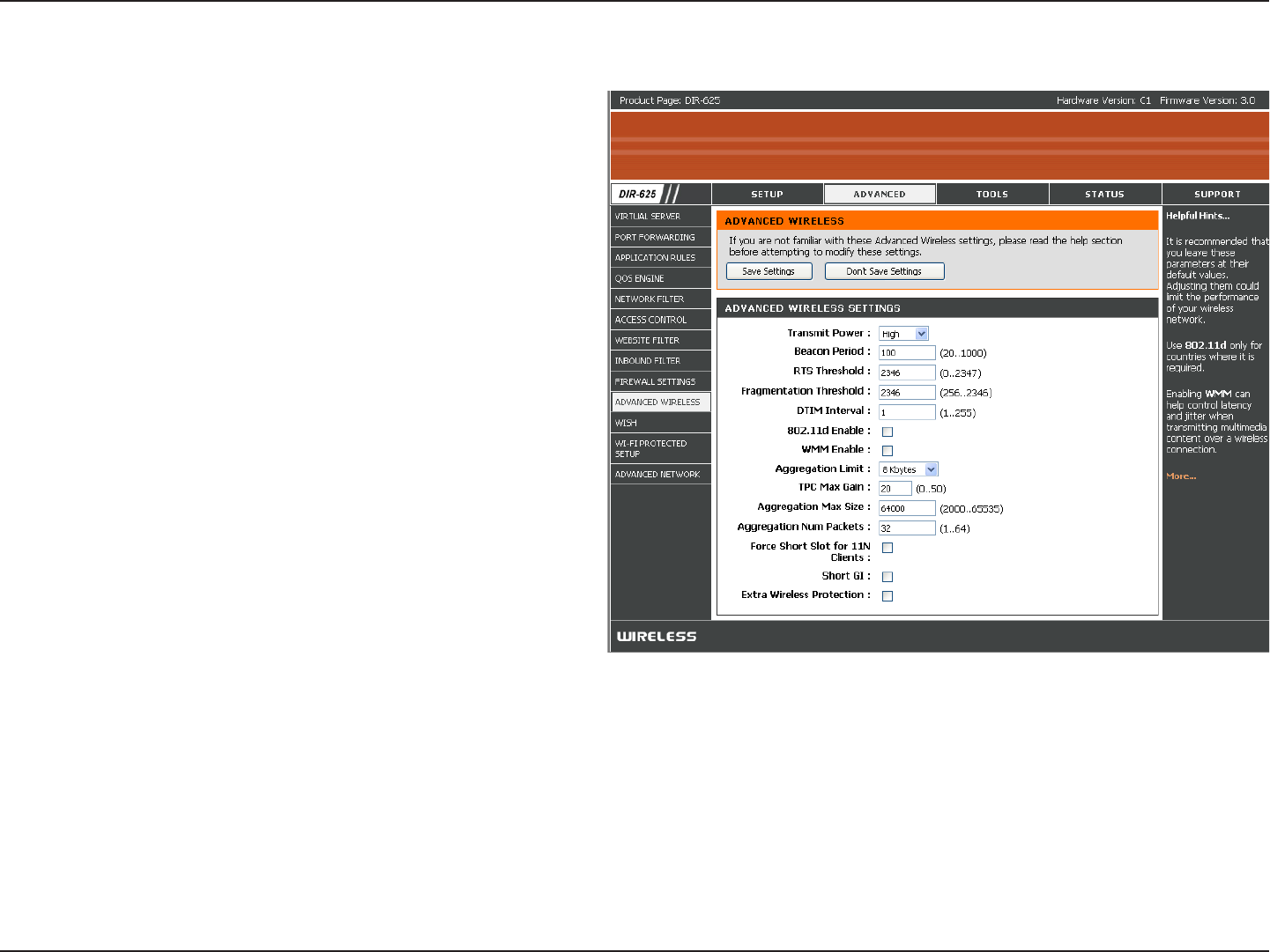
Set the transmit power of the antennas.
Beacons are packets sent by an Access Point to
synchronize a wireless network. Specify a value.
100 is the default setting and is recommended.
This value should remain at its default setting of
2432. If inconsistent data flow is a problem, only a
minor modification should be made.
The fragmentation threshold, which is specified
in bytes, determines whether packets will be
fragmented. Packets exceeding the 2346 byte
setting will be fragmented before transmission. 2346
is the default setting.
(Delivery Traffic Indication Message) 3 is the default
setting. A DTIM is a countdown informing clients
of the next window for listening to broadcast and
multicast messages.
This enables 802.11d opration. 802.11d is a wireless
specification developed to allow implementation of
wireless networks in countries that cannot use the
802.11 standard. This feature should only be enabled if you are in a country that requires it.
WMM is QoS for your wireless network. This will improve the quality of video and voice applications for your wireless
clients.
Check this box to reduce the guard interval time therefore increasing the data capacity. However, it’s less reliable and may
create higher data loss.
Transmit Power:
Beacon Period:
RTS Threshold:
Fragmentation
Threshold:
DTIM Interval:
802.11d:
WMM Function:
Short GI:
Advanced Wireless Settings
48D-Link DIR-625 User Manual
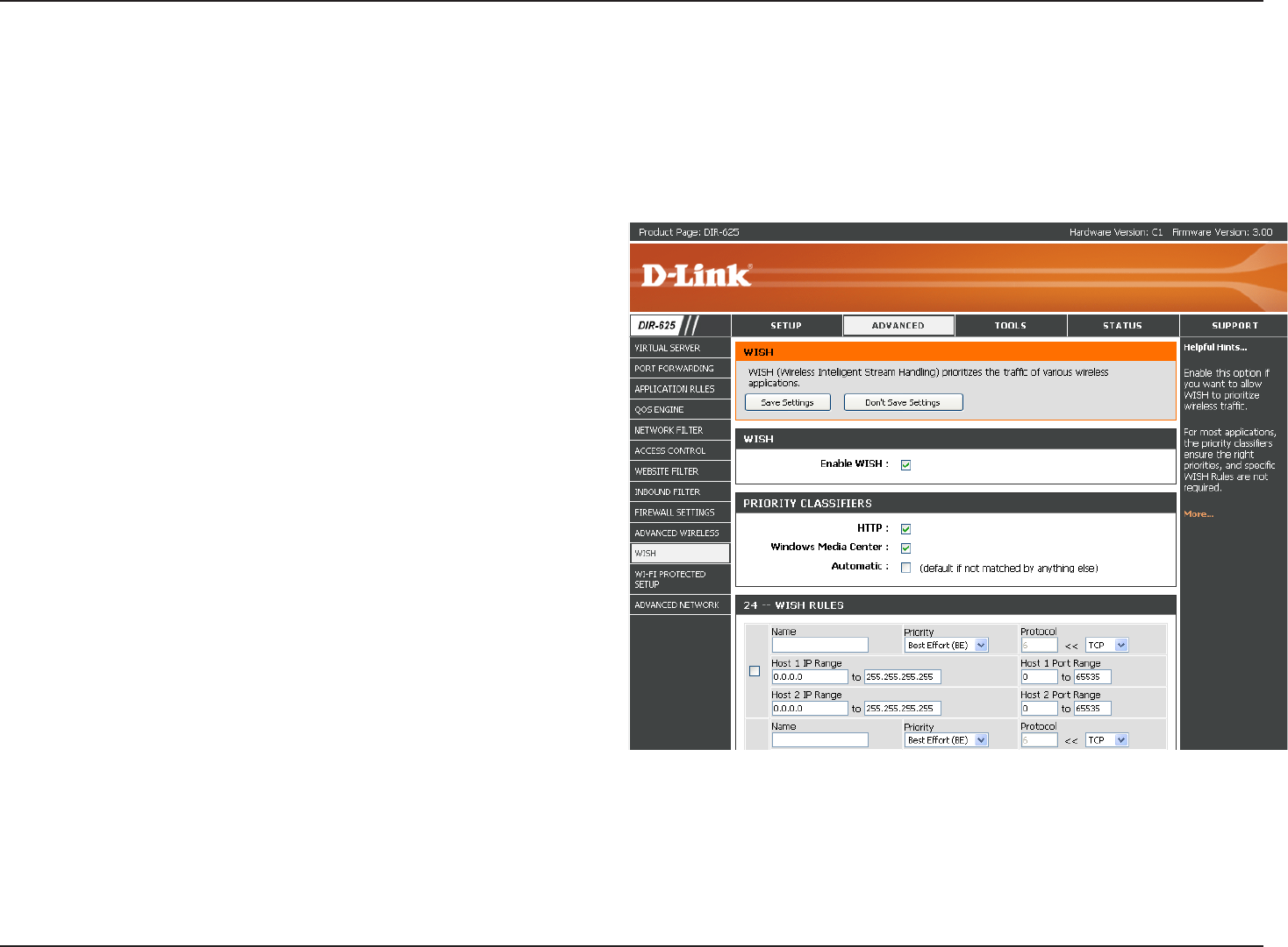
Section 3 - Configuration
Enable this option if you want to allow WISH to
prioritize your traffic.
Allows the router to recognize HTTP transfers
for many common audio and video streams and
prioritize them above other traffic. Such streams
are frequently used by digital media players.
Enables the router to recognize certain audio and
video streams generated by a Windows Media
Center PC and to prioritize these above other
traffic. Such streams are used by systems known
as Windows Media Extenders, such as the Xbox
360.
When enabled, this option causes the router to
automatically attempt to prioritize traffic streams
that it doesn’t otherwise recognize, based on
the behavior that the streams exhibit. This acts
to deprioritize streams that exhibit bulk transfer
characteristics, such as file transfers, while leaving
interactive traffic, such as gaming or VoIP, running
at a normal priority.
A WISH Rule identifies a specific message flow and assigns a priority to that flow. For most applications, the priority classifiers
ensure the right priorities and specific WISH Rules are not required. WISH supports overlaps between rules. If more than
one rule matches for a specific message flow, the rule with the highest priority will be used.
Enable WISH:
HTTP:
Windows Media
Center:
Automatic:
WISH Rules:
WISH
WISH is short for Wireless Intelligent Stream Handling, a technology developed to enhance your experience of using
a wireless network by prioritizing the traffic of different applications. The WISH configuration has a max of 24 Rules
that can be defined.

49D-Link DIR-625 User Manual
Section 3 - Configuration
Name:
Priority:
Protocol:
Host 1 IP Range:
Host 1 Port Range:
Host 2 IP Range:
Host 2 IP Range:
Create a name for the rule that is meaningful to you.
The priority of the message flow is entered here. Four priorities are defined:
• BK: Background (least urgent).
• BE: Best Effort
• VI: Video
• VO: Voice (most urgent)
The protocol used by the messages.
The rule applies to a flow of messages for which one computer’s IP address falls within the range set here.
The rule applies to a flow of messages for which host 1’s port number is within the range set here.
The rule applies to a flow of messages for which the other computer’s IP address falls within the range set here.
The rule applies to a flow of messages for which host 2’s port number is within the range set here.
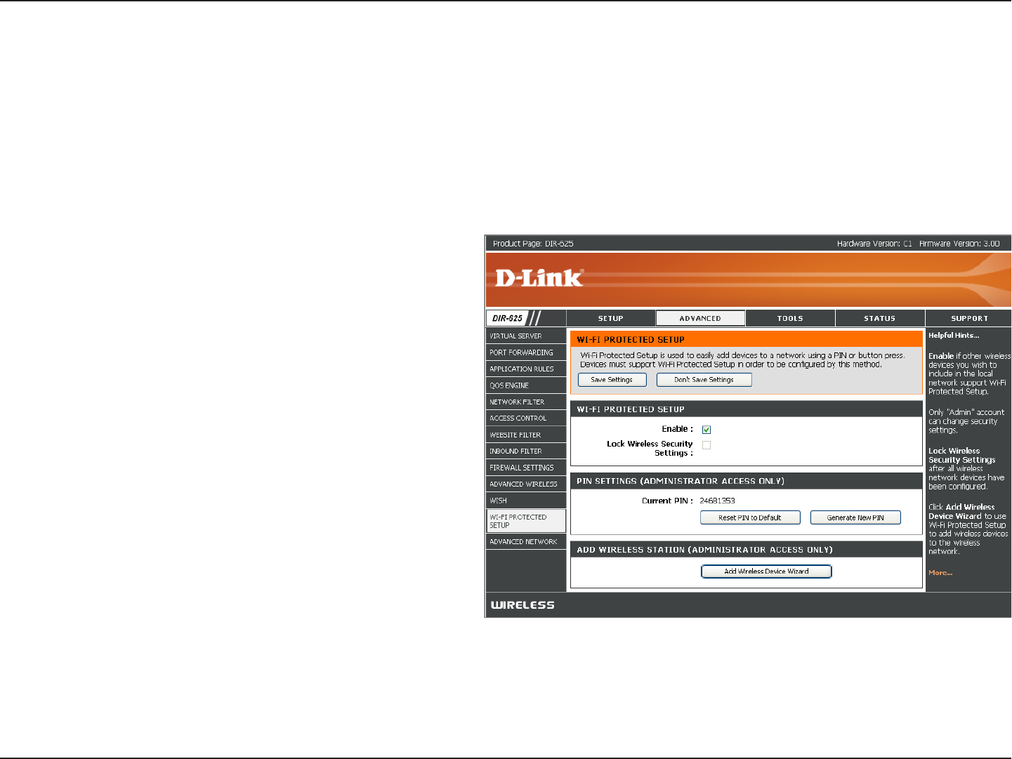
50D-Link DIR-625 User Manual
Section 3 - Configuration
Enable the Wi-Fi Protected Setup feature.
Locking the wireless security settings prevents the
settings from being changed by the Wi-Fi Protected
Setup feature of the router. Devices can still be
added to the network using Wi-Fi Protected Setup.
However, the settings of the network will not change
once this option is checked.
A PIN is a unique number that can be used to add
the router to an existing network or to create a new
network. The default PIN may be printed on the
bottom of the router. For extra security, a new PIN
can be generated. You can restore the default PIN at
any time. Only the Administrator (“admin” account)
can change or reset the PIN.
Shows the current value of the router’s PIN.
Restore the default PIN of the router.
Create a random number that is a valid PIN. This becomes the router’s PIN. You can then copy this PIN to the user interface
of the registrar.
Enable:
Lock Wireless
Security Settings:
PIN Settings:
Current PIN:
Reset PIN to
Default:
Generate New PIN:
Wi-Fi Protected Setup
Wi-Fi Protected Setup (WPS) System is a simplified method for securing your wireless network during the “Initial setup”
as well as the “Add New Device” processes. The Wi-Fi Alliance (WFA) has certified it across different products as well
as manufactures. The process is just as easy, as depressing a button for the Push-Button Method or correctly entering
the 8-digit code for the Pin-Code Method. The time reduction in setup and ease of use are quite beneficial, while the
highest wireless Security setting of WPA2 is automatically used.