D Link Des 3226 Users Manual DHS Fast Ethernet Switch
DES-3226 to the manual 2b2f3179-ee0e-4d9e-963c-2f58b39ff1e8
2015-01-25
: D-Link D-Link-Des-3226-Users-Manual-218021 d-link-des-3226-users-manual-218021 d-link pdf
Open the PDF directly: View PDF ![]() .
.
Page Count: 179 [warning: Documents this large are best viewed by clicking the View PDF Link!]
- About This Guide
- Introduction
- Unpacking and Setup
- Identifying External Components
- Connecting The Switch
- Switch Management and Operating Concepts
- Configuring the Switch Using the Console Interface
- Before You Start
- Connecting to the Switch
- User Accounts Management
- Save Changes
- Configuration
- Configure IP Address
- Configure Switch Information and Advanced Settings
- Configure Ports
- Configure Bandwidth
- Configure Spanning Tree Protocol
- Configure Static (Destination-Address Filtering) Table
- Configure VLANs
- Configure IGMP Snooping
- Configure Port LACP Trunking
- Configure Port Mirroring
- Configure Threshold of Broadcast/Multicast/DA-Unknown Storm
- Configure Port Security
- Configure Class of Service, Default Priority and Traffic Class
- Configure Port GMRP Settings
- Configure DIFFSERV Settings
- Configure Port Access Entity
- Network Monitoring
- SNMP Manager Configuration
- System Utilities
- Reboot
- Web-Based Network Management
- Introduction
- Getting Started
- Configuration
- Management
- Monitoring
- Maintenance
- Help
- Technical Specifications
- RJ-45 Pin Specification
- Runtime Switching Software Default Settings
- Understanding and Troubleshooting the Spanning Tree Protocol
- Brief Review of Bitwise Logical Operations
- Index

DES-3226
Managed Standalone Fast Ethernet Switch
User’s Guide
Second Edition (July 2002)
651ES3226025
Printed In Taiwan
RECYCLABLE
Wichtige Sicherheitshinweise
1. Bitte lesen Sie sich diese Hinweise sorgfältig durch.
2. Heben Sie diese Anleitung für den spätern Gebrauch auf.
3. Vor jedem Reinigen ist das Gerät vom Stromnetz zu trennen. Vervenden Sie keine Flüssig- oder Aerosolreiniger. Am besten dient ein
angefeuchtetes Tuch zur Reinigung.
4. Um eine Beschädigung des Gerätes zu vermeiden sollten Sie nur Zubehörteile verwenden, die vom Hersteller zugelassen sind.
5. Das Gerät is vor Feuchtigkeit zu schützen.
6. Bei der Aufstellung des Gerätes ist auf sichern Stand zu achten. Ein Kippen oder Fallen könnte Verletzungen hervorrufen. Verwenden Sie nur
sichere Standorte und beachten Sie die Aufstellhinweise des Herstellers.
7. Die Belüftungsöffnungen dienen zur Luftzirkulation die das Gerät vor Überhitzung schützt. Sorgen Sie dafür, daß diese Öffnungen nicht
abgedeckt werden.
8. Beachten Sie beim Anschluß an das Stromnetz die Anschlußwerte.
9. Die Netzanschlußsteckdose muß aus Gründen der elektrischen Sicherheit einen Schutzleiterkontakt haben.
10. Verlegen Sie die Netzanschlußleitung so, daß niemand darüber fallen kann. Es sollete auch nichts auf der Leitung abgestellt werden.
11. Alle Hinweise und Warnungen die sich am Geräten befinden sind zu beachten.
12. Wird das Gerät über einen längeren Zeitraum nicht benutzt, sollten Sie es vom Stromnetz trennen. Somit wird im Falle einer Überspannung
eine Beschädigung vermieden.
13. Durch die Lüftungsöffnungen dürfen niemals Gegenstände oder Flüssigkeiten in das Gerät gelangen. Dies könnte einen Brand bzw.
Elektrischen Schlag auslösen.
14. Öffnen Sie niemals das Gerät. Das Gerät darf aus Gründen der elektrischen Sicherheit nur von authorisiertem Servicepersonal geöffnet
werden.
15. Wenn folgende Situationen auftreten ist das Gerät vom Stromnetz zu trennen und von einer qualifizierten Servicestelle zu überprüfen:
a – Netzkabel oder Netzstecker sint beschädigt.
b – Flüssigkeit ist in das Gerät eingedrungen.
c – Das Gerät war Feuchtigkeit ausgesetzt.
d – Wenn das Gerät nicht der Bedienungsanleitung ensprechend funktioniert oder Sie mit Hilfe dieser Anleitung keine Verbesserung erzielen.
e – Das Gerät ist gefallen und/oder das Gehäuse ist beschädigt.
f – Wenn das Gerät deutliche Anzeichen eines Defektes aufweist.
16. Bei Reparaturen dürfen nur Orginalersatzteile bzw. den Orginalteilen entsprechende Teile verwendet werden. Der Einsatz von ungeeigneten
Ersatzteilen kann eine weitere Beschädigung hervorrufen.
17. Wenden Sie sich mit allen Fragen die Service und Repartur betreffen an Ihren Servicepartner. Somit stellen Sie die Betriebssicherheit des
Gerätes sicher.
18. Zum Netzanschluß dieses Gerätes ist eine geprüfte Leitung zu verwenden, Für einen Nennstrom bis 6A und einem Gerätegewicht grőßer 3kg ist
eine Leitung nicht leichter als H05VV-F, 3G, 0.75mm2 einzusetzen.

Trademarks
Copyright D-Link Corporation 2002. Contents subject to change without prior notice. D-Link is a registered
trademark of D-Link Corporation/D-Link Systems, Inc. All other trademarks belong to their respective proprietors.
Copyright Statement
No part of this publication may be reproduced in any form or by any means or used to make any derivative such as
translation, transformation, or adaptation without permission from D-Link Corporation/D-Link Systems Inc., as
stipulated by the United States Copyright Act of 1976.
Limited Warranty
Hardware:
D-Link warrants its hardware products to be free from defects in workmanship and materials, under normal use and service, for
the following periods measured from date of purchase from D-Link or its Authorized Reseller:
Product Type Warranty Period
Complete products One year
Spare parts and spare kits 90 days
The one-year period of warranty on complete products applies on condition that the product's Registration Card is filled out and
returned to a D-Link office within ninety (90) days of purchase. A list of D-Link offices is provided at the back of this manual,
together with a copy of the Registration Card. Failing such timely registration of purchase, the warranty period shall be limited to
90 days.
If the product proves defective within the applicable warranty period, D-Link will provide repair or replacement of the product.
D-Link shall have the sole discretion whether to repair or replace, and replacement product may be new or reconditioned.
Replacement product shall be of equivalent or better specifications, relative to the defective product, but need not be identical.
Any product or part repaired by D-Link pursuant to this warranty shall have a warranty period of not less than 90 days, from
date of such repair, irrespective of any earlier expiration of original warranty period. When D-Link provides replacement, then
the defective product becomes the property of D-Link.
Warranty service may be obtained by contacting a D-Link office within the applicable warranty period, and requesting a Return
Material Authorization (RMA) number. If a Registration Card for the product in question has not been returned to D-Link, then a
proof of purchase (such as a copy of the dated purchase invoice) must be provided. If Purchaser's circumstances require special
handling of warranty correction, then at the time of requesting RMA number, Purchaser may also propose special procedure as
may be suitable to the case.
After an RMA number is issued, the defective product must be packaged securely in the original or other suitable shipping
package to ensure that it will not be damaged in transit, and the RMA number must be prominently marked on the outside of the
package. The package must be mailed or otherwise shipped to D-Link with all costs of mailing/shipping/insurance prepaid;
D-Link will ordinarily reimburse Purchaser for mailing/shipping/insurance expenses incurred for return of defective product in
accordance with this warranty. D-Link shall never be responsible for any software, firmware, information, or memory data of
Purchaser contained in, stored on, or integrated with any product returned to D-Link pursuant to this warranty.
Any package returned to D-Link without an RMA number will be rejected and shipped back to Purchaser at Purchaser's expense,
and D-Link reserves the right in such a case to levy a reasonable handling charge in addition mailing or shipping costs.
Software:
Warranty service for software products may be obtained by contacting a D-Link office within the applicable warranty period. A
list of D-Link offices is provided at the back of this manual, together with a copy of the Registration Card. If a Registration Card
for the product in question has not been returned to a D-Link office, then a proof of purchase (such as a copy of the dated
purchase invoice) must be provided when requesting warranty service. The term "purchase" in this software warranty refers to
the purchase transaction and resulting licence to use such software.
D-Link warrants that its software products will perform in substantial conformance with the applicable product documentation
provided by D-Link with such software product, for a period of ninety (90) days from the date of purchase from D-Link or its
Authorized Reseller. D-Link warrants the magnetic media, on which D-Link provides its software product, against failure during
the same warranty period. This warranty applies to purchased software, and to replacement software provided by D-Link
pursuant to this warranty, but shall not apply to any update or replacement which may be provided for download via the Internet,
or to any update which may otherwise be provided free of charge.
D-Link's sole obligation under this software warranty shall be to replace any defective software product with product which
substantially conforms to D-Link's applicable product documentation. Purchaser assumes responsibility for the selection of
appropriate application and system/platform software and associated reference materials. D-Link makes no warranty that its
software products will work in combination with any hardware, or any application or system/platform software product provided
by any third party, excepting only such products as are expressly represented, in D-Link's applicable product documentation as
being compatible. D-Link's obligation under this warranty shall be a reasonable effort to provide compatibility, but D-Link shall
have no obligation to provide compatibility when there is fault in the third-party hardware or software. D-Link makes no
warranty that operation of its software products will be uninterrupted or absolutely error-free, and no warranty that all defects in
the software product, within or without the scope of D-Link's applicable product documentation, will be corrected.
LIMITATION OF WARRANTIES
IF THE D-LINK PRODUCT DOES NOT OPERATE AS WARRANTED ABOVE, THE CUSTOMER'S SOLE REMEDY SHALL BE, AT D-
LINK'S OPTION, REPAIR OR REPLACEMENT. THE FOREGOING WARRANTIES AND REMEDIES ARE EXCLUSIVE AND ARE IN
LIEU OF ALL OTHER WARRANTIES, EXPRESSED OR IMPLIED, EITHER IN FACT OR BY OPERATION OF LAW, STATUTORY OR
OTHERWISE, INCLUDING WARRANTIES OF MERCHANTABILITY AND FITNESS FOR A PARTICULAR PURPOSE. D-LINK
NEITHER ASSUMES NOR AUTHORIZES ANY OTHER PERSON TO ASSUME FOR IT ANY OTHER LIABILITY IN CONNECTION
WITH THE SALE, INSTALLATION MAINTENANCE OR USE OF D-LINK'S PRODUCTS
D-LINK SHALL NOT BE LIABLE UNDER THIS WARRANTY IF ITS TESTING AND EXAMINATION DISCLOSE THAT THE ALLEGED
DEFECT IN THE PRODUCT DOES NOT EXIST OR WAS CAUSED BY THE CUSTOMER'S OR ANY THIRD PERSON'S MISUSE,
NEGLECT, IMPROPER INSTALLATION OR TESTING, UNAUTHORIZED ATTEMPTS TO REPAIR, OR ANY OTHER CAUSE BEYOND
THE RANGE OF THE INTENDED USE, OR BY ACCIDENT, FIRE, LIGHTNING OR OTHER HAZARD.
LIMITATION OF LIABILITY
IN NO EVENT WILL D-LINK BE LIABLE FOR ANY DAMAGES, INCLUDING LOSS OF DATA, LOSS OF PROFITS, COST OF COVER
OR OTHER INCIDENTAL, CONSEQUENTIAL OR INDIRECT DAMAGES ARISING OUT THE INSTALLATION, MAINTENANCE, USE,
PERFORMANCE, FAILURE OR INTERRUPTION OF A D- LINK PRODUCT, HOWEVER CAUSED AND ON ANY THEORY OF
LIABILITY. THIS LIMITATION WILL APPLY EVEN IF D-LINK HAS BEEN ADVISED OF THE POSSIBILITY OF SUCH DAMAGE.
IF YOU PURCHASED A D-LINK PRODUCT IN THE UNITED STATES, SOME STATES DO NOT ALLOW THE LIMITATION OR
EXCLUSION OF LIABILITY FOR INCIDENTAL OR CONSEQUENTIAL DAMAGES, SO THE ABOVE LIMITATION MAY NOT APPLY
TO YOU.
D-Link Offices for Registration and Warranty Service
The product's Registration Card, provided at the back of this manual, must be sent to a D-Link office. To obtain an RMA number
for warranty service as to a hardware product, or to obtain warranty service as to a software product, contact the D-Link office
nearest you. An addresses/telephone/fax list of D-Link offices is provided in the back of this manual.
FCC Warning
This equipment has been tested and found to comply with the limits for a Class A digital device, pursuant to Part 15 of the FCC
Rules. These limits are designed to provide reasonable protection against harmful interference when the equipment is operated in
a commercial environment. This equipment generates, uses, and can radiate radio frequency energy and, if not installed and used
in accordance with this user’s guide, may cause harmful interference to radio communications. Operation of this equipment in a
residential area is likely to cause harmful interference in which case the user will be required to correct the interference at his
own expense.
This device complies with part 15 of the FCC Rules. Operation is subject to the following two conditions: (1) This device may not
cause harmful interference, and (2) this device must accept any interference received, including interference that may cause
undesired operation.
CE Mark Warning
This is a Class A product. In a domestic environment, this product may cause radio interference in which case the
user may be required to take adequate measures.
Warnung!
Dies ist ein Produkt der Klasse A. Im Wohnbereich kann dieses Produkt Funkstoerungen verursachen.
In diesem Fall kann vom Benutzer verlangt werden, angemessene Massnahmen zu ergreifen.
Precaución!
Este es un producto de Clase A. En un entorno doméstico, puede causar interferencias de radio, en
cuyo case, puede requerirse al usuario para que adopte las medidas adecuadas.
Attention!
Ceci est un produit de classe A. Dans un environnement domestique, ce produit pourrait causer des
interférences radio, auquel cas l`utilisateur devrait prendre les mesures adéquates.
Attenzione!
Il presente prodotto appartiene alla classe A. Se utilizzato in ambiente domestico il prodotto può
causare interferenze radio, nel cui caso è possibile che l`utente debba assumere provvedimenti
adeguati.
VCCI Warning
BSMI Warning

Table of Contents
About This Guide .................................................................................................................................. 1
Overview of this User’s Guide ............................................................................................................. 1
Introduction.......................................................................................................................................... 2
Features ............................................................................................................................................. 2
Ports ................................................................................................................................................ 2
Performance Features......................................................................................................................... 2
Management .................................................................................................................................... 3
Unpacking and Setup............................................................................................................................ 5
Unpacking .......................................................................................................................................... 5
Installation ......................................................................................................................................... 5
Desktop or Shelf Installation ............................................................................................................ 5
Rack Installation.............................................................................................................................. 6
Power on............................................................................................................................................. 7
Power Failure ................................................................................................................................... 7
Identifying External Components .......................................................................................................... 8
Front Panel......................................................................................................................................... 8
Rear Panel .......................................................................................................................................... 8
Side Panels......................................................................................................................................... 9
Optional 100BASE and 1000BASE Extension Modules....................................................................... 9
LED Indicators ................................................................................................................................. 13
Connecting The Switch........................................................................................................................ 14
Switch to End Node .......................................................................................................................... 14
Switch to Hub or Switch ................................................................................................................... 14
Switch Management and Operating Concepts ..................................................................................... 16
Local Console Management .............................................................................................................. 16
Diagnostic (console) port (RS-232 DCE)..........................................................................................16
IP Addresses and SNMP Community Names ..................................................................................... 17
Traps................................................................................................................................................ 18
MIBs................................................................................................................................................. 19
SNMP ............................................................................................................................................... 19
Authentication ............................................................................................................................... 19
Packet Forwarding ............................................................................................................................ 20
MAC Address Aging Time ............................................................................................................... 20
Filtering............................................................................................................................................ 20
Spanning Tree Protocol..................................................................................................................... 21
STP Operation Levels ..................................................................................................................... 21
Bridge Protocol Data Units ............................................................................................................. 22
Creating a Stable STP Topology ...................................................................................................... 23
STP Port States .............................................................................................................................. 23
User-Changeable STP Parameters ..................................................................................................25
Illustration of STP .......................................................................................................................... 25
VLANs .............................................................................................................................................. 27
Notes About VLANs on the DES-3226 ............................................................................................ 27
IEEE 802.1Q VLANs....................................................................................................................... 27
802.1Q VLAN Packet Forwarding ...................................................................................................28
802.1Q VLAN Tags ......................................................................................................................... 29
Port VLAN ID.................................................................................................................................. 30
vii

Tagging and Untagging................................................................................................................... 31
Ingress Filtering ............................................................................................................................. 31
VLANs............................................................................................................................................ 32
DHCP ............................................................................................................................................... 33
802.1X Port-based Network Access Control ...................................................................................... 34
Configuring the Switch Using the Console Interface ............................................................................ 37
Before You Start ............................................................................................................................... 37
Connecting to the Switch.................................................................................................................. 37
User Accounts Management ............................................................................................................. 39
Save Changes ................................................................................................................................... 41
Factory Reset ................................................................................................................................. 42
Configuration ................................................................................................................................... 45
Configure IP Address...................................................................................................................... 45
Configure Switch Information and Advanced Settings .................................................................... 47
Configure Ports .............................................................................................................................. 49
Configure Bandwidth ..................................................................................................................... 50
Configure Spanning Tree Protocol .................................................................................................. 51
Configure Static (Destination-Address Filtering) Table.................................................................... 53
Configure VLANs ............................................................................................................................ 55
Configure IGMP Snooping .............................................................................................................. 59
Configure Port LACP Trunking ....................................................................................................... 61
Configure Port Mirroring ................................................................................................................ 62
Configure Threshold of Broadcast/Multicast/DA-Unknown Storm ................................................. 63
Configure Port Security .................................................................................................................. 63
Configure Class of Service, Default Priority and Traffic Class ......................................................... 64
Configure Port GMRP Settings........................................................................................................ 66
Configure DIFFSERV Settings ........................................................................................................ 66
Configure Port Access Entity .......................................................................................................... 67
Network Monitoring .......................................................................................................................... 74
Port Utilization ............................................................................................................................... 74
Port Error Packets.......................................................................................................................... 75
Port Packet Analysis....................................................................................................................... 75
Browse MAC Address ..................................................................................................................... 76
Switch History................................................................................................................................ 77
IGMP Snooping .............................................................................................................................. 77
Dynamic Group Registration Table................................................................................................. 78
VLAN Status .................................................................................................................................. 78
Port Access Control Statistics......................................................................................................... 79
SNMP Manager Configuration........................................................................................................... 82
System Utilities ................................................................................................................................ 84
Upgrade Firmware from TFTP Server.............................................................................................. 84
Use Configuration File on TFTP Server ...........................................................................................85
Save Settings to TFTP Server.......................................................................................................... 85
Save History Log to TFTP Server..................................................................................................... 86
Ping Test ........................................................................................................................................ 86
Reboot .............................................................................................................................................. 87
Web-Based Network Management ....................................................................................................... 89
Introduction ..................................................................................................................................... 89
Getting Started ................................................................................................................................. 89
Configuration ................................................................................................................................... 91
IP Address...................................................................................................................................... 91
Switch Information......................................................................................................................... 92
Advanced Settings.......................................................................................................................... 93
Port Configuration.......................................................................................................................... 95
Port Mirroring ................................................................................................................................ 96
viii

Port LACP Trunking ....................................................................................................................... 97
IGMP Snooping .............................................................................................................................. 98
Port GMRP ................................................................................................................................... 100
Diffserv Settings........................................................................................................................... 101
Spanning Tree.............................................................................................................................. 102
Static Filtering Table .................................................................................................................... 104
VLANs.......................................................................................................................................... 105
Port Bandwidth ............................................................................................................................ 108
Threshold of Broadcast ................................................................................................................ 109
Port Priority.................................................................................................................................. 110
Class of Traffic ............................................................................................................................. 111
Class of Service ............................................................................................................................ 111
Port Security ................................................................................................................................ 112
PAE System Control ..................................................................................................................... 112
Radius Server............................................................................................................................... 117
Management................................................................................................................................... 119
Security IP ................................................................................................................................... 119
SNMP Manager ............................................................................................................................ 120
Trap Manager............................................................................................................................... 120
User Accounts.............................................................................................................................. 121
Monitoring...................................................................................................................................... 122
Port Utilization ............................................................................................................................. 122
Packets ........................................................................................................................................ 123
Errors .......................................................................................................................................... 127
Size .............................................................................................................................................. 131
MAC Address ............................................................................................................................... 133
IGMP Snooping ............................................................................................................................ 135
Dynamic Group Registration ........................................................................................................ 135
VLAN Status ................................................................................................................................ 136
Port Access Control ...................................................................................................................... 136
Maintenance................................................................................................................................... 141
TFTP Services............................................................................................................................... 141
Switch History.............................................................................................................................. 144
Ping Test ...................................................................................................................................... 145
Save Changes............................................................................................................................... 145
Factory Reset ............................................................................................................................... 146
Restart System............................................................................................................................. 146
Connection Timeout ..................................................................................................................... 147
Logout.......................................................................................................................................... 147
Help................................................................................................................................................ 147
Technical Specifications .................................................................................................................... 148
RJ-45 Pin Specification ..................................................................................................................... 150
Runtime Switching Software Default Settings.................................................................................... 152
Understanding and Troubleshooting the Spanning Tree Protocol....................................................... 153
Blocking State.............................................................................................................................. 153
Listening State ............................................................................................................................. 154
Learning State.............................................................................................................................. 155
Forwarding State.......................................................................................................................... 156
Disabled State.............................................................................................................................. 156
Troubleshooting STP....................................................................................................................... 158
Spanning Tree Protocol Failure .................................................................................................... 158
Full/Half Duplex Mismatch.......................................................................................................... 158
Unidirectional Link ...................................................................................................................... 159
ix

Packet Corruption ........................................................................................................................ 160
Resource Errors ........................................................................................................................... 160
Identifying a Data Loop ................................................................................................................ 160
Avoiding Trouble .......................................................................................................................... 160
Brief Review of Bitwise Logical Operations......................................................................................... 163
Index................................................................................................................................................. 164
x

DES-3226 NWay Standalone Fast Ethernet Switch User’s Guide
ABOUT THIS GUIDE
This User’s Guide tells you how to install your DES-3226, how to connect it to your Ethernet/Fast
Ethernet/Gigabit Ethernet network, and how to set its configuration using the built-in console
interface.
Overview of this User’s Guide
• Chapter 1, “Introduction.” Describes the Switch and its features.
• Chapter 2, “Unpacking and Setup.” Helps you get started with the basic installation of the Switch.
• Chapter 3, “Identifying External Components.” Describes the front panel, rear panel, optional
plug-in modules, and LED indicators of the Switch.
• Chapter 4, “Connecting the Switch.” Tells how you can connect the Switch to your Ethernet/Fast
Ethernet/Gigabit Ethernet network.
• Chapter 5, “Switch Management and Operating Concepts.” Talks about Local Console
Management via the RS-232 DCE console port and other aspects about how to manage the
Switch.
• Chapter 6, “Using the Console Interface.” Tells how to use the built-in console interface to change,
set, and monitor Switch performance and security.
• Chapter 7, “Web-Based Network Management.” Tells how to manage the Switch through an
Internet browser.
• Appendix A, “Technical Specifications.” Lists the technical specifications of the Switch.
• Appendix B, “RJ-45 Pin Specifications.” Shows the details and pin assignments for the RJ-45
receptacle/connector.
• Appendix C, “Factory Default Settings.”
• Appendix D, “Understanding and Troubleshooting the Spanning Tree Protocol.”
• Appendix E, “Brief Review of Bitwise Logical Operations.”
1

DES-3226 NWay Standalone Fast Ethernet Switch User’s Guide
1
INTRODUCTION
This section describes the features of the DES-3226.
Features
The Switch was designed for easy installation and high performance in an environment where traffic on
the network and the number of users increases continuously.
Switch features include:
Ports
• 24 (DES-3226) high performance NWay (MDI-II/MDI-X) ports for connecting to end stations,
servers and hubs. Every port can be used for an uplink connection.
• All UTP ports can auto-negotiate (NWay) between 10Mbps/100Mbps, half-duplex or full duplex,
and feature flow control.
• One front panel slide-in module interface for a 1-port 100BASE-FX (2Km), 2-port 100BASE-FX
(2Km), 1-port 100BASE-FL (15Km), 2-port 100BASE-FL (15Km), 2-port 1000BASE-SX, 2-port
1000BASE-LX, 2-port 1000BASE-T, or 2-port GBIC to connect to another switch, server or
network backbone.
• RS-232 DCE Diagnostic port (console port) for setting up and managing the Switch via a
connection to a console terminal or PC using a terminal emulation program.
Performance Features
• 8.8 Gbps switching fabric capacity
• Store and forward switching scheme.
• Full and half-duplex for both 10Mbps and 100Mbps connections. Full duplex allows the switch
port to simultaneously transmit and receive data, and only works with connections to full-duplex
capable end stations and switches. Connections to hubs must take place at half duplex.
• Auto-polarity detection and correction of incorrect polarity on the transmit and receive twisted-
pair at each port.
• Data forwarding rate 14,880 pps per port at 100% of wire-speed for 10Mbps speed.
• Data forwarding rate 148,800 pps per port at 100% of wire-speed for 100Mbps speed.
2

DES-3226 NWay Standalone Fast Ethernet Switch User’s Guide
• Data filtering rate eliminates all error packets, runts, etc. at 14,880 pps per port at 100% of wire-
speed for 10Mbps speed.
• Data filtering rate eliminates all error packets, runts, etc. at 148,800 pps per port at 100% of
wire-speed for 100Mbps speed.
• 8K active MAC address entry table per device with automatic learning and aging (10 to 1000000
seconds).
• 8 MB packet buffer per device.
• 802.1D Spanning Tree support.
• 802.1Q Tagged VLAN support, including GVRP (GARP VLAN Registration Protocol) support for
automatic VLAN configuration distribution. All the supported VLANs (including dynamic joined
VLANs by GVRP and user-defined VLANs and the one reserved VLAN) can be up to 255.
• IGMP Snooping support.
• Port trunking support.
• RADIUS client support.
• EAPOL support.
• 802.1X port-based authentication support. Authentication methods: EAP MD5-Challenge (RFC
1994) and EAP TLS Authentication Protocol (RFC 2716).
Management
• RS-232 console port for out-of-band network management via a console terminal.
• Spanning Tree Algorithm Protocol for creation of alternative backup paths and prevention of
network loops.
• SNMP V.1/V.2C Agent.
• Fully configurable either in-band or out-of-band control via SNMP based software.
• Flash memory for software upgrades. This can be done in-band via TFTP or out-of-band via the
console.
• Built-in SNMP management:
Bridge MIB (RFC 1493)
MIB-II (RFC 1213)
802.1p MIB (RFC 2674)
802.1q MIB (RFC 2674)
Entity MIB (RFC 2737)
IF-MIB (RFC 2233)
Ether-Like MIB (RFC 2358) –dot3StatsTable
SNMP V.2-MIB (RFC 1907)
3

DES-3226 NWay Standalone Fast Ethernet Switch User’s Guide
802.1X MIB
Enterprise MIB
Mini-RMON MIB (RFC 1757) – 4 groups. The RMON specification defines the Counters for
the Receive functions only. However, the DES-3226 implements counters for both receive
and transmit functions.
• Supports Web-based management.
• TFTP support.
• BOOTP support.
• DHCP Client support.
• Password enabled.
• Telnet remote control console support.
4

DES-3226 NWay Standalone Fast Ethernet Switch User’s Guide
2
UNPACKING AND SETUP
This chapter provides unpacking and setup information for the Switch.
Unpacking
Open the shipping carton of the Switch and carefully unpack its contents. The carton should contain
the following items:
• One DES-3226 24-Port NWay Standalone Fast Ethernet Switch
• Mounting kit: 2 mounting brackets and screws
• Four rubber feet with adhesive backing
• One AC power cord
• This User’s Guide with Registration Card
If any item is found missing or damaged, please contact your local reseller for replacement.
Installation
Use the following guidelines when choosing a place to install the Switch:
• The surface must support at least 3 kg.
• The power outlet should be within 1.82 meters (6 feet) of the device.
• Visually inspect the power cord and see that it is secured to the AC power connector.
• Make sure that there is proper heat dissipation from and adequate ventilation around the
Switch. Do not place heavy objects on the Switch.
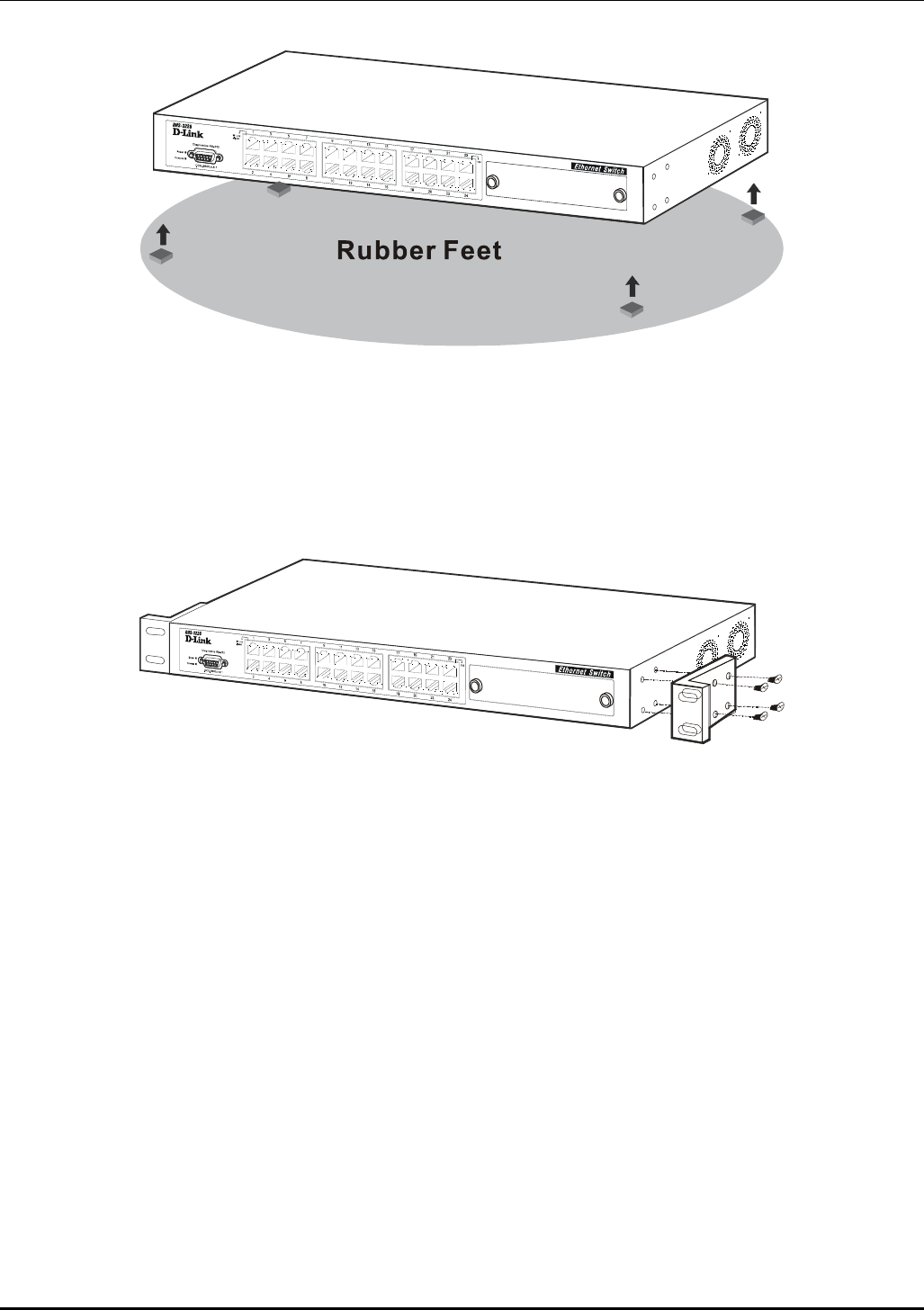
Desktop or Shelf Installation
When installing the Switch on a desktop or shelf, the rubber feet included with the device should first
be attached. Attach these cushioning feet on the bottom at each corner of the device. Allow adequate
space for ventilation between the device and the objects around it.
5
DES-3226 NWay Standalone Fast Ethernet Switch User’s Guide
Figure 2-1. Installing rubber feet for desktop installation
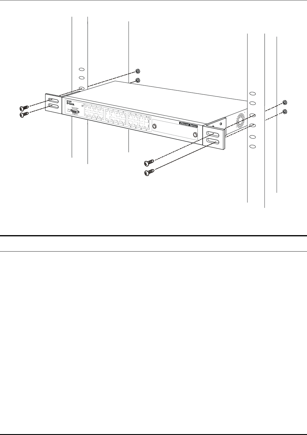
Rack Installation
The DES-3226 can be mounted in an EIA standard-sized, 19-inch rack, which can be placed in a wiring
closet with other equipment. To install, attach the mounting brackets on the Switch’s side panels (one
on each side) and secure them with the screws provided.
Figure 2- 2A. Attaching the mounting brackets to the Switch
Then, use the screws provided with the equipment rack to mount the Switch on the rack.
6
DES-3226 NWay Standalone Fast Ethernet Switch User’s Guide
Figure 2-2B. Installing the Switch in an equipment rack
Power on
The Switch can be used with AC power supply 100-240 VAC, 50 - 60 Hz. The Switch’s power supply
will adjust to the local power source automatically and may be powered on without having any or all
LAN segment cables connected.
After the Switch is plugged in, the LED indicators should respond as follows:
• All LED indicators will momentarily blink. This blinking of the LED indicators represents a reset
of the system.
• The power LED indicator will blink while the Switch loads onboard software and performs a self-
test. After approximately 20 seconds, the LED will light again to indicate the switch is in a ready
state.
Power Failure
As a precaution in the event of a power failure, unplug the Switch. When power is resumed, plug the
Switch back in.
7
DES-3226 NWay Standalone Fast Ethernet Switch User’s Guide
3
IDENTIFYING EXTERNAL COMPONENTS
This chapter describes the front panel, rear panel, side panels, optional plug-in modules, and LED
indicators of the DES-3226.
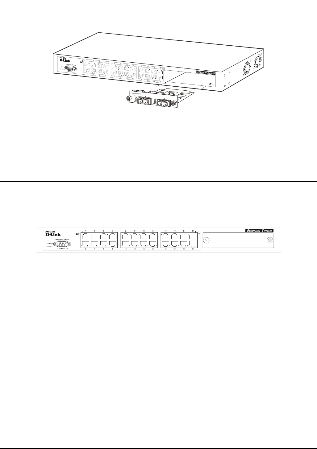
Front Panel
The front panel of the Switch consists of LED indicators, an RS-232 communication port, a slide-in
module slot, and either 10, 18 or 24 MDI-X/MDI-II Ethernet/Fast Ethernet (10/100 Mbps) ports, each
of which is capable of making an uplink connection.
Figure 3-1. Front panel view of the Switch
• Comprehensive LED indicators display the status of the Switch and the network (see the LED
Indicators section below).
• An RS-232 DCE console port for setting up and managing the Switch via a connection to a
console terminal or PC using a terminal emulation program.
• A front-panel slide-in module slot can accommodate a 1-port 100BASE-FX (2Km), 2-port
100BASE-FX (2Km), 1-port 100BASE-FL (15Km), 2-port 100BASE-FL (15Km), 2-port 1000BASE-
SX, 2-port 1000BASE-LX, 2-port 1000BASE-T, or 2-port GBIC module to connect to another
switch, server or network backbone.
• Twenty-four high-performance, NWay Ethernet ports all of which operate at 10/100 Mbps for
connections to end stations, servers and hubs. All ports can auto-negotiate between 10Mbps or
100Mbps and full or half duplex.
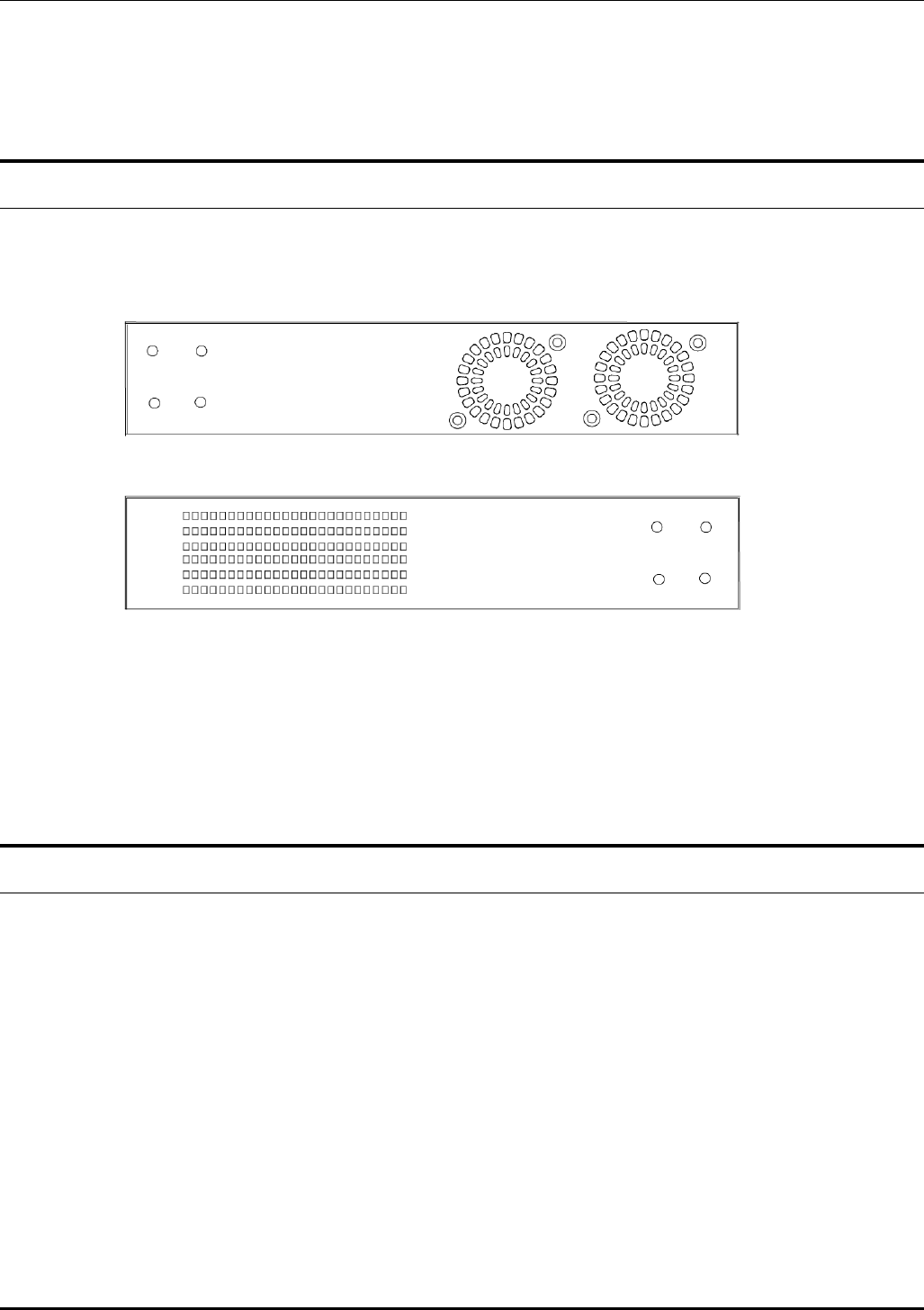
Rear Panel
The rear panel of the Switch contains an AC power connector.
Figure 3-2. Rear panel view of the Switch
8
DES-3226 NWay Standalone Fast Ethernet Switch User’s Guide
• The AC power connector is a standard three-pronged connector that supports the power cord.
Plug-in the female connector of the provided power cord into this socket, and the male side of the
cord into a power outlet. Supported input voltages range from 100 ~ 240 VAC at 50 ~ 60 Hz.
Side Panels
The right side panel of the Switch contains two system fans (see the top part of the diagram below). The
left side panel contains heat vents.
Figure 3-3. Side panel views of the Switch
• The system fans are used to dissipate heat. The sides of the system also provide heat vents to
serve the same purpose. Do not block these openings, and leave at least 6 inches of space at the
rear and sides of the switch for proper ventilation. Be reminded that without proper heat
dissipation and air circulation, system components might overheat, which could lead to system
failure.
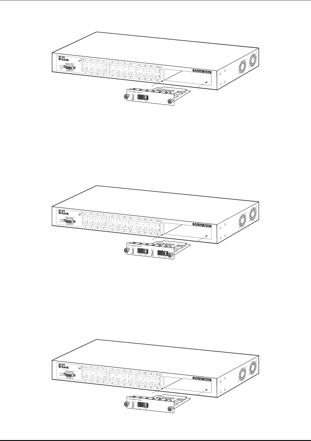
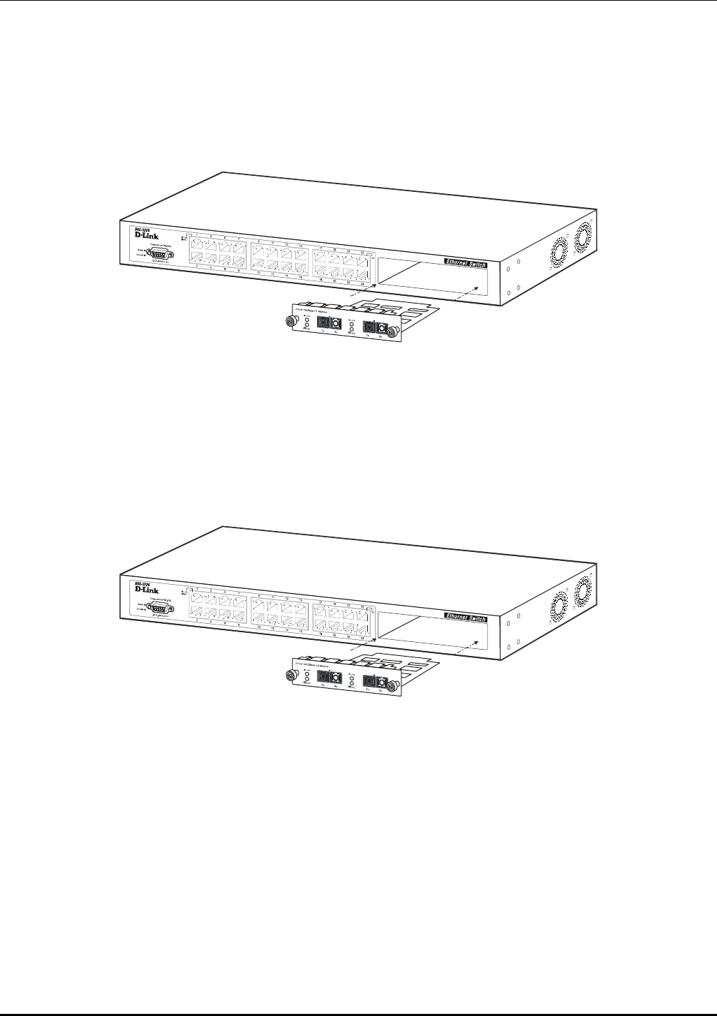
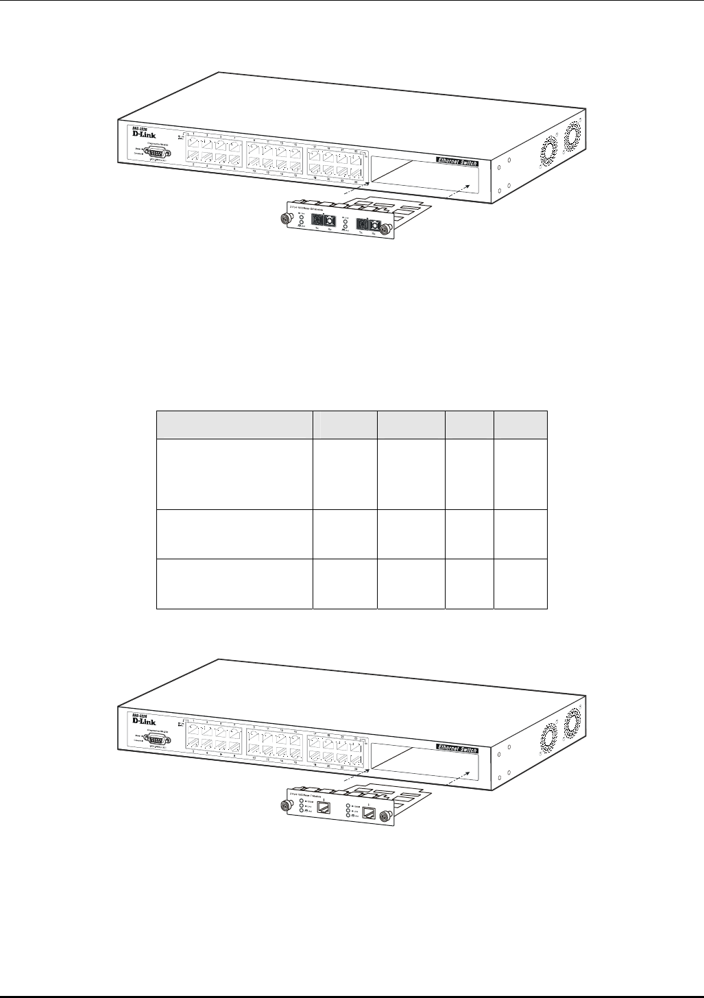
Optional 100BASE and 1000BASE Extension Modules
The Switch is able to accommodate a range of optional plug-in modules in order to increase
functionality and performance. These modules must be purchased separately.
9
DES-3226 NWay Standalone Fast Ethernet Switch User’s Guide
100BASE-FX Module (2Km)
Figure 3-4. Optional 100BASE 1-port front panel module
• One 100BASE-FX (with SC type connector) Fiber port.
• Fully compliant with IEEE802.3u.
• Support Full-duplex operation only.
• IEEE 802.3x compliant Flow Control support for full duplex.
100BASE-FX Module (2Km)
Figure 3-5. Optional 100BASE 2-port front panel module
• Two 100BASE-FX (with SC type connector) Fiber ports.
• Fully compliant with IEEE802.3u.
• Support Full-duplex operation only.
• IEEE 802.3x compliant Flow Control support for full duplex.
100BASE-FL Module (15Km)
Figure 3-6. Optional 100BASE 1-port front panel module
10
DES-3226 NWay Standalone Fast Ethernet Switch User’s Guide
• One 100BASE-FL (with SC type connector) port.
• Fully compliant with IEEE802.3u.
• Support Full-duplex operation only.
• IEEE 802.3x compliant Flow Control support for full duplex.
100BASE-FL Module (15Km)
Figure 3-7. Optional 100BASE 2-port front panel module
• Two 100BASE-FL (with SC type connector) ports.
• Fully compliant with IEEE802.3u.
• Support Full-duplex operation only.
• IEEE 802.3x compliant Flow Control support for full duplex.
1000BASE-LX Gigabit Module
Figure 3-8. Optional 1000BASE-LX 2-port front panel module
• Two 1000BASE-LX ports.
• Connects to 1000BASE-LX devices at full duplex or auto.
• Allows connections up to 5 km in length using single-mode fiber optic cable.
11
DES-3226 NWay Standalone Fast Ethernet Switch User’s Guide
1000BASE-SX Gigabit Module
Figure 3-9. Optional 1000BASE-SX 2-port front panel module
• Two 1000BASE-SX ports.
• Connects to 1000BASE-SX devices at full duplex or auto.
• IEEE 802.3x compliant Flow Control support for full duplex.
• Supports multi-mode fiber-optic cable connections of up to 2 km.
• Allows connections using multi-mode fiber optic cable in the following configurations:
62.5µm 62.5µm 50µm 50µm
Modal bandwidth
(min. overfilled launch)
Unit: MHz*km
160 200 400 500
Operating distance
Unit: meters
220 275 500 550
Channel insertion loss
Unit: dB
2.33 2.53 3.25 3.43
1000BASE-T Copper Gigabit Module
Figure 3-10. Optional 1000BASE-T Copper 2-port front panel module
• Two 1000BASE-T Copper ports.
• Connects to 1000BASE-T devices at 1000M/full duplex, 100M/full duplex, 100M/half duplex, and
Auto.
• Supports Category 5+ or higher cable connections of up to 100 meters.
12
DES-3226 NWay Standalone Fast Ethernet Switch User’s Guide
1000BASE GBIC Module
Figure 3-11. Optional 1000BASE GBIC 2-port front panel module
• Two 1000BASE GBIC ports.
• Connects to GBIC devices at full duplex only.
• Allows multi-mode fiber optic cable runs of up to 550m in full-duplex mode (only).
LED Indicators
The LED indicators of the Switch include Power, Console, Speed, and Link/Act. The following shows the
LED indicators for the Switch along with an explanation of each indicator.
Figure 3-12. The LED indicators
• Power – This indicator on the front panel should be lit during the Power-On Self Test (POST). It
will light green approximately 2 seconds after the switch is powered on to indicate the ready state
of the device.
• Console – This indicator is lit green when the Switch is being managed via out-of-band/local
console management through the RS-232 console port using a straight-through serial cable.
• Speed – On the right of each twisted pair port, this LED will light when the corresponding port is
operating at 100 Mbps. An unlit LED indicates a connection speed of 10 Mbps.
• Link/Act – These indicators are located to the left of each port. They are lit when there is a
secure connection (or link) to a device at any of the ports. The LEDs blink whenever there is
reception or transmission (i.e. Activity--Act) of data occurring at a port.
13
DES-3226 NWay Standalone Fast Ethernet Switch User’s Guide
4
CONNECTING THE SWITCH
This chapter describes how to connect the DES-3226 to your Ethernet/Fast Ethernet/Gigabit Ethernet
network.
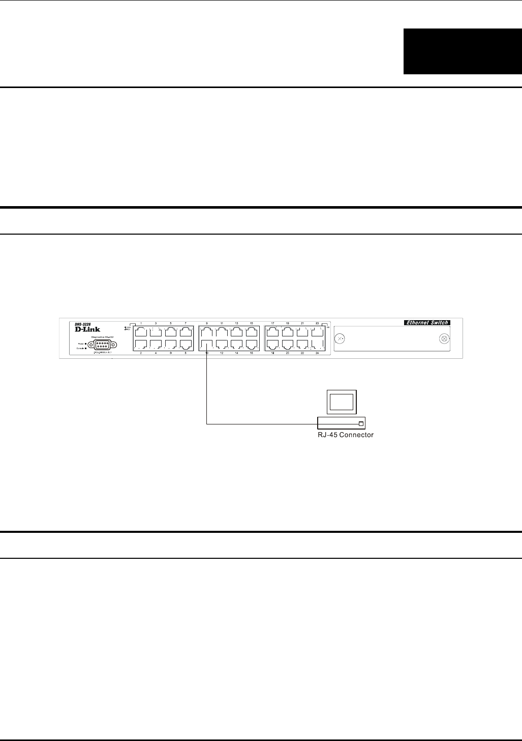
Switch to End Node
End nodes include PCs outfitted with a 10, 100 or 10/100 Mbps RJ-45 Ethernet/Fast Ethernet/Gigabit
Ethernet Network Interface Card (NIC) and most routers.
An end node can be connected to the Switch via a two-pair Category 3, 4, or 5 UTP/STP cable. The end
node should be connected to any of the ports of the Switch.
Figure 4-1. Switch connected to an End Node
The Link/Act LEDs for each UTP port light green when the link is valid. The LED on the right side of
the port indicates port speed. It will light for 100 Mbps connections only. A blinking LED on the left
side indicates packet activity on that port.
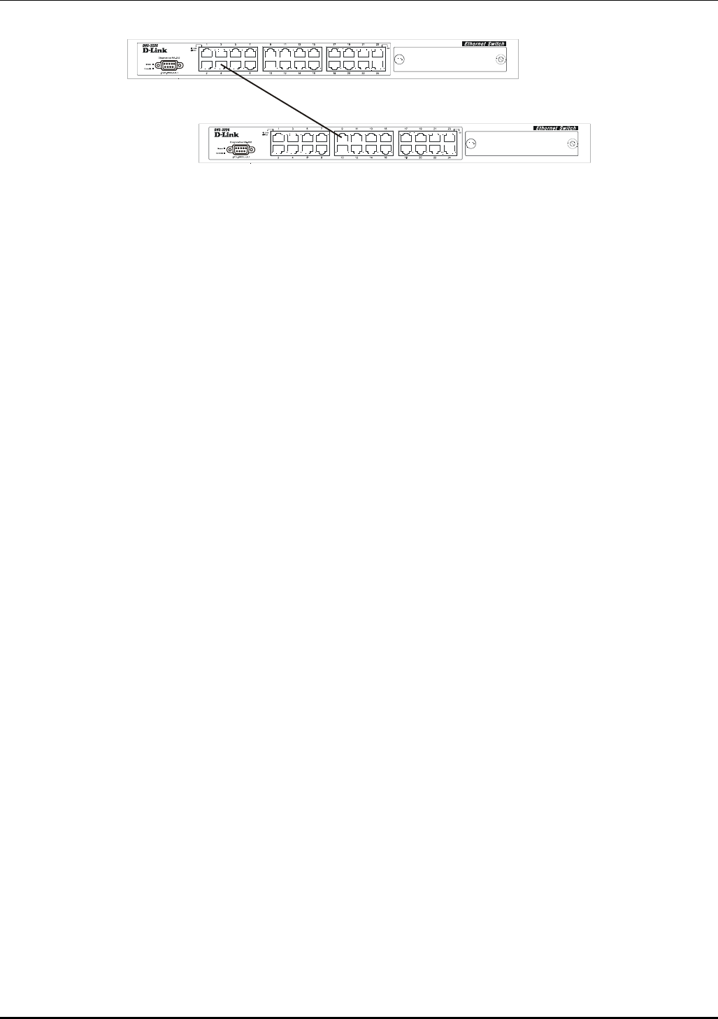
Switch to Hub or Switch
These connections can be accomplished in a number of ways using a normal cable.
• A 10BASE-T hub or switch can be connected to the Switch via a two-pair Category 3, 4 or 5
UTP/STP cable.
• A 100BASE-TX hub or switch can be connected to the Switch via a two-pair Category 5 UTP/STP
cable.
14
DES-3226 NWay Standalone Fast Ethernet Switch User’s Guide
Figure 4-2. Switch connected to a normal (non-Uplink) port on a hub or switch using a straight or crossover
cable
15

DES-3226 NWay Standalone Fast Ethernet Switch User’s Guide
5
SWITCH MANAGEMENT AND OPERATING
CONCEPTS
This chapter discusses many of the concepts and features used to manage the Switch, as well as the
concepts necessary for the user to understand the functioning of the switch. Further, this chapter
explains many important points regarding these features.
Configuring the Switch to implement these concepts and make use of its many features is discussed in
detail in the next chapters.
Local Console Management
A local console is a terminal or a workstation running a terminal emulation program that is connected
directly to the switch via the RS-232 console port on the front of the Switch. A console connection is
referred to as an ‘Out-of-Band’ connection, meaning that console is connected to the Switch using a
different circuit than that used for normal network communications. So, the console can be used to set
up and manage the Switch even if the network is down.
Local console management uses the terminal connection to operate the console program built-in to the
Switch (see Chapter 6, “Using the Console Interface”). A network administrator can manage, control and
monitor the switch from the console program.
The DES-3226 contains a CPU, memory for data storage, flash memory for configuration data,
operational programs, and SNMP agent firmware. These components allow the Switch to be actively
managed and monitored from either the console port or the network itself (out-of-band, or in-band).
Diagnostic (console) port (RS-232 DCE)
Out-of-band management requires connecting a terminal, such as a VT-100 or a PC running a terminal
emulation program (such as HyperTerminal, which is automatically installed with Microsoft Windows) a
to the RS-232 DCE console port of the Switch. Switch management using the RS-232 DCE console port
is called Local Console Management to differentiate it from management performed via management
platforms, such as D-View, HP OpenView, etc.
The console port is set at the factory for the following configuration:
• Baud rate: 9,600
• Data width: 8 bits
• Parity: none
• Stop bits: 1
• Flow Control None
16
DES-3226 NWay Standalone Fast Ethernet Switch User’s Guide
Make sure the terminal or PC you are using to make this connection is configured to match these
settings.
If you are having problems making this connection on a PC, make sure the emulation is set to VT-
100. If you still don’t see anything, try hitting <Ctrl> + r to refresh the screen.
IP Addresses and SNMP Community Names
Each Switch must be assigned its own IP Address, which is used for communication with an SNMP
network manager or other TCP/IP application (for example BOOTP, TFTP). The Switch’s default IP
address is 10.90.90.90. You can change the default Switch IP Address to meet the specification of your
networking address scheme.
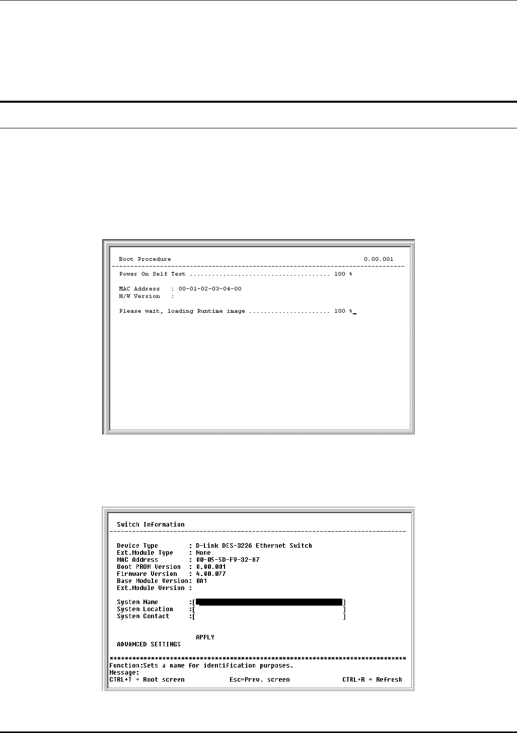
The Switch is also assigned a unique MAC address by the factory. This MAC address cannot be
changed, and can be found from the initial boot console screen – shown below.
Figure 5-1. Boot Procedure screen
The Switch’s MAC address can also be found from the console program under the Switch Information
menu item, as shown below.
Figure 5-2. Switch Information menu
17

DES-3226 NWay Standalone Fast Ethernet Switch User’s Guide
In addition, you can also set an IP Address for a gateway router. This becomes necessary when the
network management station is located on a different IP network from the Switch, making it necessary
for management packets to go through a router to reach the network manager, and vice-versa.
For security, you can set in the Switch a list of IP Addresses of the network managers that allow you to
manage the Switch. You can also change the default SNMP Community Strings in the Switch and set
the access rights of these Community Strings. In addition, a VLAN may be designated as a Management
VLAN.
Traps
Traps are messages that alert you of events that occur on the Switch. The events can be as serious as a
reboot (someone accidentally turned OFF the Switch), or less serious like a port status change. The
Switch generates traps and sends them to the network manager (trap recipient).
Trap recipients are special users of the network who are given certain rights and access in overseeing
the maintenance of the network. Trap recipients will receive traps sent from the Switch; they must
immediately take certain actions to avoid future failure or breakdown of the network.
You can also specify which network managers may receive traps from the Switch by entering a list of
the IP addresses of authorized network managers. Up to four trap recipient IP addresses, and four
corresponding SNMP community strings can be entered.
SNMP community strings function like passwords in that the community string entered for a given IP
address must be used in the management station software, or a trap will be sent.
The following are trap types the Switch can send to a trap recipient:
• Cold Start – This trap signifies that the Switch has been powered up and initialized such that
software settings are reconfigured and hardware systems are rebooted. A cold start is different
from a factory reset in that configuration settings saved to non-volatile RAM used to
reconfigure the switch.
• Warm Start – This trap signifies that the Switch has been rebooted, however the POST (Power
On Self-Test) is skipped.
• Authentication Failure – This trap signifies that someone has tried to logon to the switch
using an invalid SNMP community string. The Switch automatically stores the source IP
address of the unauthorized user.
• New Root – This trap indicates that the Switch has become the new root of the Spanning
Tree, the trap is sent by the switch soon after its election as the new root. This implies that
upon expiration of the Topology Change Timer the new root trap is sent out immediately after
the Switch’s election as the new root.
• Topology Change (STP) – A Topology Change trap is sent by the Switch when any of its
configured ports transitions from the Learning state to the Forwarding state, or from the
Forwarding state to the Blocking state. The trap is not sent if a new root trap is sent for the
same transition.
• Link Up – This trap is sent whenever the link of a port changes from link down to link up.
• Link Down – This trap is sent whenever the link of a port changes from link up to link down.
18

DES-3226 NWay Standalone Fast Ethernet Switch User’s Guide
MIBs
Management and counter information are stored in the Switch in the Management Information Base
(MIB). The Switch uses the standard MIB-II Management Information Base module. Consequently,
values for MIB objects can be retrieved from any SNMP-based network management software. In
addition to the standard MIB-II, the Switch also supports its own proprietary enterprise MIB as an
extended Management Information Base. These MIBs may also be retrieved by specifying the MIB’s
Object-Identity (OID) at the network manager. MIB values can be either read-only or read-write.
Read-only MIBs variables can be either constants that are programmed into the Switch, or variables
that change while the Switch is in operation. Examples of read-only constants are the number of port
and type of ports. Examples of read-only variables are the statistics counters such as the number of
errors that have occurred, or how many kilobytes of data have been received and forwarded through a
port.
Read-write MIBs are variables usually related to user-customized configurations. Examples of these are
the Switch’s IP Address, Spanning Tree Algorithm parameters, and port status.
If you use a third-party vendors’ SNMP software to manage the Switch, a diskette listing the Switch’s
propriety enterprise MIBs can be obtained by request. If your software provides functions to browse or
modify MIBs, you can also get the MIB values and change them (if the MIBs’ attributes permit the write
operation). This process however can be quite involved, since you must know the MIB OIDs and retrieve
them one by one.
SNMP
The Simple Network Management Protocol (SNMP) is an OSI layer 7 (the application layer) protocol for
remotely monitoring and configuring network devices. SNMP enables network management stations to
read and modify the settings of gateways, routers, switches, and other network devices. SNMP can be
used to perform many of the same functions as a directly connected console, or can be used within an
integrated network management software package such as HP OpenView or DView.
SNMP performs the following functions:
• Sending and receiving SNMP packets through the IP protocol.
• Collecting information about the status and current configuration of network devices.
• Modifying the configuration of network devices.
The DES-3226 has a software program called an ‘agent’ that processes SNMP requests, but the user
program that makes the requests and collects the responses runs on a management station (a
designated computer on the network). The SNMP agent and the user program both use the UDP/IP
protocol to exchange packets.
Authentication
The authentication protocol ensures that both the router SNMP agent and the remote user SNMP
application program discard packets from unauthorized users. Authentication is accomplished using
‘community strings’, which function like passwords. The remote user SNMP application and the router
SNMP must use the same community string. SNMP community strings of up to 20 characters may be
entered under the Remote Management Setup menu of the console program.
19

DES-3226 NWay Standalone Fast Ethernet Switch User’s Guide
Packet Forwarding
The Switch enters the relationship between destination MAC or IP addresses and the Ethernet port or
gateway router the destination resides on into its forwarding table. This information is then used to
forward packets. This reduces the traffic congestion on the network, because packets, instead of being
transmitted to all ports, are transmitted to the destination port only. Example: if Port 1 receives a
packet destined for a station on Port 2, the Switch transmits that packet through Port 2 only, and
transmits nothing through the other ports. This process is referred to as ‘learning’ the network
topology.
MAC Address Aging Time
The Aging Time affects the learning process of the Switch. Dynamic forwarding table entries, which are
made up of the source and destination MAC addresses and their associated port numbers, are deleted
from the table if they are not accessed within the aging time.
The aging time can be from 10 to 1,000,000 seconds with a default value of 300 seconds. A very long
aging time can result in dynamic forwarding table entries that are out-of-date or no longer exist. This
may cause incorrect packet forwarding decisions by the Switch.
If the Aging Time is too short however, many entries may be aged out too soon. This will result in a high
percentage of received packets whose source addresses cannot be found in the forwarding table, in
which case the switch will broadcast the packet to all ports, negating many of the benefits of having a
switch.
Static forwarding entries are not affected by the aging time.
Filtering
The Switch uses a filtering database to segment the network and control communication between
segments. It can also filter packets off the network for intrusion control. Static filtering entries can
be made by MAC Address or IP Address filtering.
Each port on the Switch is a unique collision domain and the switch filters (discards) packets whose
destination lies on the same port as where it originated. This keeps local packets from disrupting
communications on other parts of the network.
For intrusion control, whenever a Switch encounters a packet originating from or destined to a MAC
address or an IP Address entered into the filter table, the switch will discard the packet.
Some filtering is done automatically by the Switch:
• Dynamic filtering – automatic learning and aging of MAC addresses and their location on the
network. Filtering occurs to keep local traffic confined to its segment.
• Filtering done by the Spanning Tree Protocol that can filter packets based on topology,
making sure that signal loops don’t occur.
• Filtering done for VLAN integrity. Packets from a member of a VLAN (VLAN 2, for example)
destined for a device on another VLAN (VLAN 3) will be filtered.
Some filtering requires the manual entry of information into a filtering table:
20

DES-3226 NWay Standalone Fast Ethernet Switch User’s Guide
• MAC address filtering – the manual entry of specific MAC addresses to be filtered from the
network. Packets sent from one manually entered MAC address can be filtered from the
network. The entry may be specified as source, destination, or both.
Spanning Tree Protocol
The IEEE 802.1D Spanning Tree Protocol allows for the blocking of links between switches that form
loops within the network. When multiple links between switches are detected, a primary link is
established. Duplicated links are blocked from use and become standby links. The protocol allows for
the duplicate links to be used in the event of a failure of the primary link. Once the Spanning Tree
Protocol is configured and enabled, primary links are established and duplicated links are blocked
automatically. The reactivation of the blocked links (at the time of a primary link failure) is also
accomplished automatically – without operator intervention.
This automatic network reconfiguration provides maximum uptime to network users. However, the
concepts of the Spanning Tree Algorithm and protocol are a complicated and complex subject and must
be fully researched and understood. It is possible to cause serious degradation of the performance of
the network if the Spanning Tree is incorrectly configured. Please read the following before making any
changes from the default values.
The DES-3226 STP allows two levels of spanning trees to be configured. The first level constructs a
spanning tree on the links between switches. This is referred to as the Switch or Global level. The
second level is on a port basis. Ports are configured as individual members of a spanning tree and the
algorithm and protocol are applied to the specified ports. This is referred to as the Port or VLAN level.
The Switch STP performs the following functions:
• Creates a single spanning tree from any combination of switching or bridging elements.
• Automatically reconfigures the spanning tree to compensate for the failure, addition, or removal
of any element in the tree.
• Reconfigures the spanning tree without operator intervention.
STP Operation Levels
The Switch allows for two levels of operation: the switch level and the port level. The switch level forms
a spanning tree consisting of links between one or more switches. The port level constructs a spanning
tree consisting of groups of one or more ports. The STP operates in much the same way for both levels.
On the switch level, STP calculates the Bridge Identifier for each switch and then sets the Root Bridge
and the Designated Bridges.
On the port level, STP sets the Root Port and the Designated Ports.
The following are the user-configurable STP parameters for the switch level:
Parameter Description Default
Value
Bridge Identifier
(Not user-
configurable except
b
y
settin
g
p
riorit
y
A combination of the User-set
priority and the switch’s MAC
address. The Bridge Identifier
consists of two parts: a 16-bit
p
riorit
y
and a 48-bit Ethernet MAC
32768 + MAC
21

DES-3226 NWay Standalone Fast Ethernet Switch User’s Guide
below) address
Priority A relative priority for each switch –
lower numbers give a higher
priority and a greater chance of a
given switch being elected as the
root bridge
32768
Hello Time The length of time between
broadcasts of the hello message by
the switch
2 seconds
Maximum Age Timer Measures the age of a received
BPDU for a port and ensures that
the BPDU is discarded when its
age exceeds the value of the
maximum age timer.
20 seconds
Forward Delay Timer The amount time spent by a port
in the learning and listening states
waiting for a BPDU that may
return the port to the blocking
state.
15 seconds
Table 5-1. STP Parameters – Switch Level
The following are the user-configurable STP parameters for the port or port group level:
Variable Description Default
Value
Port Priority A relative priority for each port –
lower numbers give a higher
priority and a greater chance of a
given port being elected as the root
port
32768
Port Cost A value used by STP to evaluate
paths – STP calculates path costs
and selects the path with the
minimum cost as the active path.
100 – 100Mbps
Fast Ethernet
ports
Table 5-2. STP Parameters – Port Group Level
Bridge Protocol Data Units
For STP to arrive at a stable network topology, the following information is used:
• The unique switch identifier
• The path cost to the root associated with each switch port
• The port identifier
STP communicates between switches on the network using Bridge Protocol Data Units (BPDUs). Each
BPDU contains the following information:
• The unique identifier of the switch that the transmitting switch currently believes is the root
switch
• The path cost to the root from the transmitting port
22

DES-3226 NWay Standalone Fast Ethernet Switch User’s Guide
• The port identifier of the transmitting port
The Switch sends BPDUs to communicate and construct the spanning-tree topology. All switches
connected to the LAN on which the packet is transmitted will receive the BPDU. BPDUs are not directly
forwarded by the switch, rather the receiving switch uses the information in the frame to calculate a
BPDU, and, if the topology changes, initiates a BPDU transmission.
The communication between switches via BPDUs results in the following:
• One switch is elected as the root switch
• The shortest distance to the root switch is calculated for each switch
• A designated switch is selected. This is the switch closest to the root switch through which
packets will be forwarded to the root.
• A port for each switch is selected. This is the port providing the best path from the switch to the
root switch.
• Ports included in the STP are selected.
Creating a Stable STP Topology
If all switches have STP enabled with default settings, the switch with the lowest MAC address in the
network will become the root switch. By increasing the priority (lowering the priority number) of the
best switch, STP can be forced to select the best switch as the root switch.
When STP is enabled using the default parameters, the path between source and destination stations
in a switched network might not be ideal. For instance, connecting higher-speed links to a port that has
a higher number than the current root port can cause a root-port change. The goal is to make the
fastest link the root port.
STP Port States
The BPDUs take some time to pass through a network. This propagation delay can result in topology
changes where a port that transitioned directly from a Blocking state to a Forwarding state could create
temporary data loops. Ports must wait for new network topology information to propagate throughout
the network before starting to forward packets. They must also wait for the packet lifetime to expire for
BPDU packets that were forwarded based on the old topology. The forward delay timer is used to allow
the network topology to stabilize after a topology change. In addition, STP specifies a series of states a
port must transition through to further ensure that a stable network topology is created after a topology
change.
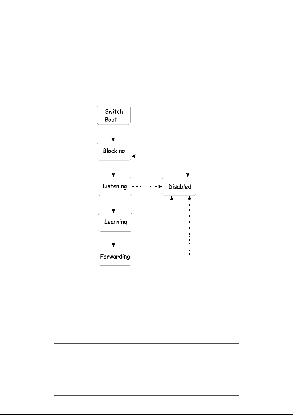
Each port on a switch using STP exists is in one of the following five states:
• Blocking – the port is blocked from forwarding or receiving packets
• Listening – the port is waiting to receive BPDU packets that may tell the port to go back to the
blocking state
• Learning – the port is adding addresses to its forwarding database, but not yet forwarding
packets
• Forwarding – the port is forwarding packets
• Disabled – the port only responds to network management messages and must return to the
blocking state first
23
DES-3226 NWay Standalone Fast Ethernet Switch User’s Guide
A port transitions from one state to another as follows:
• From initialization (switch boot) to blocking
• From blocking to listening or to disabled
• From listening to learning or to disabled
• From learning to forwarding or to disabled
• From forwarding to disabled
• From disabled to blocking
Figure 5-3. STP Port State Transitions
When you enable STP, every port on every switch in the network goes through the blocking state and
then transitions through the states of listening and learning at power up. If properly configured, each
port stabilizes to the forwarding or blocking state.
No packets (except BPDUs) are forwarded from, or received by, STP enabled ports until the forwarding
state is enabled for that port.
Default Spanning-Tree Configuration
Feature Default Value
Enable state STP enabled for all ports
Port priority 128
Port cost 100
24

DES-3226 NWay Standalone Fast Ethernet Switch User’s Guide
Bridge Priority 32,768
Table 5-3. Default STP Parameters
User-Changeable STP Parameters
The factory default setting should cover the majority of installations. However, it is advisable to keep
the default settings as set at the factory; unless, it is absolutely necessary. The user changeable
parameters in the Switch are as follows:
• Priority – A Priority for the switch can be set from 0 to 65535. 0 is equal to the highest
Priority.
• Hello Time – The Hello Time can be from 1 to 10 seconds. This is the interval between two
transmissions of BPDU packets sent by the Root Bridge to tell all other Switches that it is
indeed the Root Bridge. If you set a Hello Time for your Switch, and it is not the Root Bridge,
the set Hello Time will be used if and when your Switch becomes the Root Bridge.
Note: The Hello Time cannot be longer than the Max. Age. Otherwise, a configuration error will
occur.
• Max. Age – The Max. Age can be from 6 to 40 seconds. At the end of the Max. Age, if a BPDU
has still not been received from the Root Bridge, your Switch will start sending its own BPDU
to all other Switches for permission to become the Root Bridge. If it turns out that your
Switch has the lowest Bridge Identifier, it will become the Root Bridge.
• Forward Delay Timer – The Forward Delay can be from 4 to 30 seconds. This is the time any
port on the Switch spends in the listening state while moving from the blocking state to the
forwarding state.
Note: Observe the following formulas when setting the above parameters:
Max. Age ≤ 2 x (Forward Delay - 1 second)
Max. Age ≥ 2 x (Hello Time + 1 second)
• Port Priority – A Port Priority can be from 0 to 255. The lower the number, the greater the
probability the port will be chosen as the Root Port.
• Port Cost – A Port Cost can be set from 1 to 65535. The lower the number, the greater the
probability the port will be chosen to forward packets.
Illustration of STP
A simple illustration of three Bridges (or three switches) connected in a loop is depicted in Figure 5-3.
In this example, you can anticipate some major network problems if the STP assistance is not applied.
If Bridge A broadcasts a packet to Bridge B, Bridge B will broadcast it to Bridge C, and Bridge C will
broadcast it to back to Bridge A, and so on. The broadcast packet will be passed indefinitely in a loop,
potentially causing a network failure.
STP can be applied as shown in Figure 5-4. In this example, STP breaks the loop by blocking the
connection between Bridge B and C. The decision to block a particular connection is based on the STP
calculation of the most current Bridge and Port settings. Now, if Bridge A broadcasts a packet to Bridge
C, then Bridge C will drop the packet at port 2 and the broadcast will end there.
25
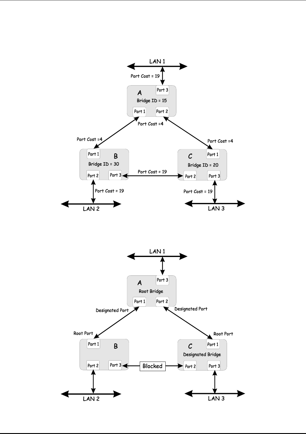
DES-3226 NWay Standalone Fast Ethernet Switch User’s Guide
Setting-up STP using values other than the defaults can be complex. Therefore, you are advised to keep
the default factory settings and STP will automatically assign root bridges/ports and block loop
connections. Influencing STP to choose a particular switch as the root bridge using the Priority
setting, or influencing STP to choose a particular port to block using the Port Priority and Port Cost
settings is, however, relatively straight forward.
Figure 5-4. Before Applying the STA Rules
In this example, only the default STP values are used.
Figure 5-5. After Applying the STA Rules
26

DES-3226 NWay Standalone Fast Ethernet Switch User’s Guide
The switch with the lowest Bridge ID (switch C) was elected the root bridge, and the ports were selected
to give a high port cost between switches B and C.
Note also that the example network topology is intended to provide redundancy to protect the network
against a link or port failure – not a switch failure or removal. For example, a failure of switch A would
isolate LAN 1 from connecting to LAN 2 or LAN 3.
VLANs
A Virtual Local Area Network (VLAN) is a network topology configured according to a logical scheme
rather than the physical layout. VLANs can be used to combine any collection of LAN segments into an
autonomous user group that appears as a single LAN. VLANs also logically segment the network into
different broadcast domains so that packets are forwarded only between ports within the VLAN.
Typically, a VLAN corresponds to a particular subnet, although not necessarily.
VLANs can enhance performance by conserving bandwidth, and improve security by limiting traffic to
specific domains.
A VLAN is a collection of end nodes grouped by logic instead of physical location. End nodes that
frequently communicate with each other are assigned to the same VLAN, regardless of where they are
physically on the network. Logically, a VLAN can be equated to a broadcast domain, because broadcast
packets are forwarded to only members of the VLAN on which the broadcast was initiated.
Notes About VLANs on the DES-3226
1. No matter what basis is used to uniquely identify end nodes and assign these nodes VLAN
membership, packets cannot cross VLANs without a network device performing a routing
function between the VLANs.
2. The DES-3226 supports only IEEE 802.1Q VLANs. The port untagging function can be used
to remove the 802.1Q tag from packet headers to maintain compatibility with devices that
are tag-unaware.
3. The Switch’s default is to assign all ports to a single 802.1Q VLAN named
DEFAULT_VLAN.
4. The DEFAULT_VLAN has a VID = 1.
5. The DES-3226 supports Asymmetric VLANs. The member ports of VLANs can be
overlapped.
IEEE 802.1Q VLANs
Some relevant terms:
• Tagging – The act of putting 802.1Q VLAN information into the header of a packet.
• Untagging – The act of stripping 802.1Q VLAN information out of the packet header.
• Ingress port – A port on a switch where packets are flowing into the switch and VLAN
decisions must be made.
27

DES-3226 NWay Standalone Fast Ethernet Switch User’s Guide
• Egress port – A port on a switch where packets are flowing out of the switch, either to
another switch or to an end station, and tagging decisions must be made.
IEEE 802.1Q (tagged) VLANs are implemented on the DES-3226. 802.1Q VLANs require tagging, which
enables them to span the entire network (assuming all switches on the network are IEEE 802.1Q-
compliant).
VLANs allow a network to be segmented in order to reduce the size of broadcast domains. All packets
entering a VLAN will only be forwarded to the stations (over IEEE 802.1Q enabled switches) that are
members of that VLAN, and this includes broadcast, multicast and unicast packets from unknown
sources.
VLANs can also provide a level of security to your network. IEEE 802.1Q VLANs will only deliver
packets between stations that are members of the VLAN.
Any port can be configured as either tagging or untagging. The untagging feature of IEEE 802.1Q VLANs
allow VLANs to work with legacy switches that don’t recognize VLAN tags in packet headers. The
tagging feature allows VLANs to span multiple 802.1Q-compliant switches through a single physical
connection and allows Spanning Tree to be enabled on all ports and work normally.
The IEEE 802.1Q standard restricts the forwarding of untagged packets to the VLAN the receiving port
is a member of.
The main characteristics of IEEE 802.1Q are as follows:
• Assigns packets to VLANs by filtering.
• Assumes the presence of a single global spanning tree.
• Uses an explicit tagging scheme with one-level tagging.
802.1Q VLAN Packet Forwarding
Packet forwarding decisions are made based upon the following three types of rules:
• Ingress rules – rules relevant to the classification of received frames belonging to a VLAN.
• Forwarding rules between ports – decides filter or forward the packet
• Egress rules – determines if the packet must be sent tagged or untagged.
28
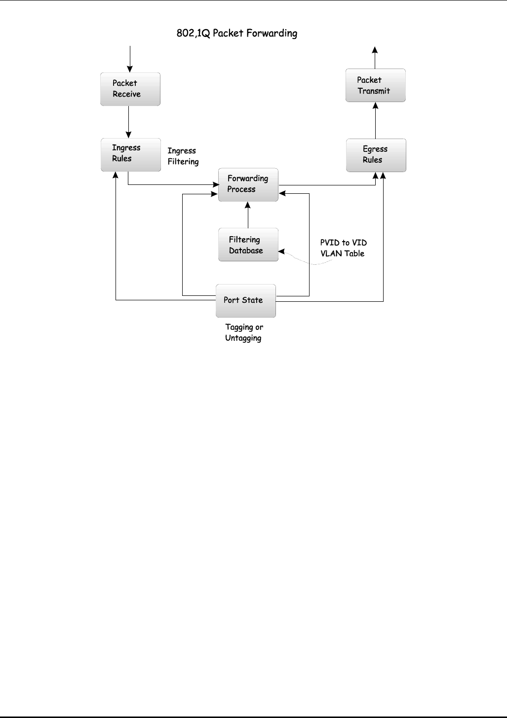
DES-3226 NWay Standalone Fast Ethernet Switch User’s Guide
Figure 5-6. IEEE 802.1Q Packet Forwarding
802.1Q VLAN Tags
The figure below shows the 802.1Q VLAN tag. There are four additional octets inserted after the source
MAC address. Their presence is indicated by a value of 0x8100 in the EtherType field. When a packet’s
EtherType field is equal to 0x8100, the packet carries the IEEE 802.1Q/802.1p tag. The tag is
contained in the following two octets and consists of 3 bits or user priority, 1 bit of Canonical Format
Identifier (CFI – used for encapsulating Token Ring packets so they can be carried across Ethernet
backbones) and 12 bits of VLAN ID (VID). The 3 bits of user priority are used by 802.1p. The VID is the
VLAN identifier and is used by the 802.1Q standard. Because the VID is 12 bits long, 4094 unique
VLANs can be identified.
The tag is inserted into the packet header making the entire packet longer by 4 octets. All of the
information contained in the packet originally is retained.
29
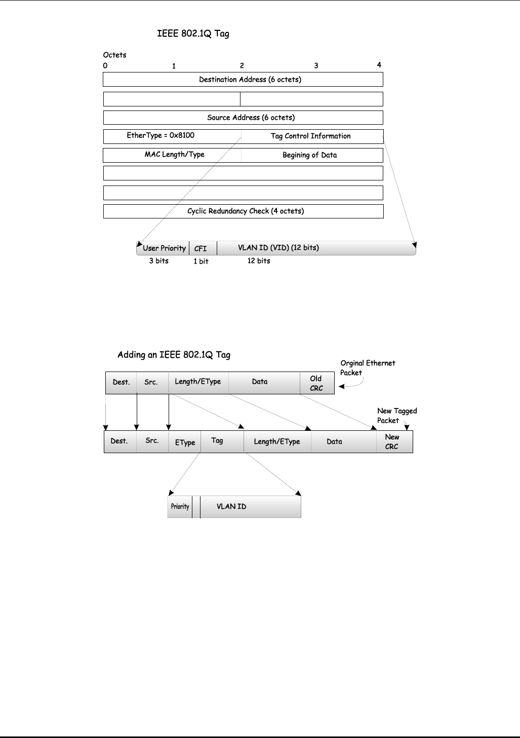
DES-3226 NWay Standalone Fast Ethernet Switch User’s Guide
Figure 5-7. IEEE 802.1Q Tag
The EtherType and VLAN ID are inserted after the MAC source address, but before the original
EtherType/Length or Logical Link Control. Because the packet is now a bit longer than it was originally,
the Cyclic Redundancy Check (CRC) must be recalculated.
Figure 5-8. Adding an IEEE 802.1Q Tag
Port VLAN ID
Packets that are tagged (are carrying the 802.1Q VID information) can be transmitted from one 802.1Q
compliant network device to another with the VLAN information intact. This allows 802.1Q VLANs to
span network devices (and indeed, the entire network – if all network devices are 802.1Q compliant).
Unfortunately, not all network devices are 802.1Q compliant. These devices are referred to as tag-
unaware. 802.1Q devices are referred to as tag-aware.
Prior to the adoption 802.1Q VLANs, port-based and MAC-based VLANs were in common use. These
VLANs relied upon a Port VLAN ID (PVID) to forward packets. A packet received on a given port would
be assigned that port’s PVID and then be forwarded to the port that corresponded to the packet’s
30

DES-3226 NWay Standalone Fast Ethernet Switch User’s Guide
destination address (found in the switch’s forwarding table). If the PVID of the port that received the
packet is different from the PVID of the port that is to transmit the packet, the switch will drop the
packet.
Within the switch, different PVIDs mean different VLANs (remember that two VLANs cannot
communicate without an external router). So, VLAN identification based upon the PVIDs cannot create
VLANs that extend outside a given switch (or switch stack).
Every physical port on a switch has a PVID. 802.1Q ports are also assigned a PVID, for use within the
switch. If no VLANs are defined on the switch, all ports are then assigned to a default VLAN with a PVID
equal to 1. Untagged packets are assigned the PVID of the port on which they were received.
Forwarding decisions are based upon this PVID, in so far as VLANs are concerned. Tagged packets are
forwarded according to the VID contained within the tag. Tagged packets are also assigned a PVID, but
the PVID is not used to make packet forwarding decisions, the VID is.
Tag-aware switches must keep a table to relate PVIDs within the switch to VIDs on the network. The
switch will compare the VID of a packet to be transmitted to the VID of the port that is to transmit the
packet. If the two VIDs are different, the switch will drop the packet. Because of the existence of the
PVID for untagged packets and the VID for tagged packets, tag-aware and tag-unaware network devices
can coexist on the same network.
A switch port can have only one PVID, but can have as many VIDs as the switch has memory in its
VLAN table to store them.
Because some devices on a network may be tag-unaware, a decision must be made at each port on a
tag-aware device before packets are transmitted – should the packet to be transmitted have a tag or
not? If the transmitting port is connected to a tag-unaware device, the packet should be untagged. If
the transmitting port is connected to a tag-aware device, the packet should be tagged.
Tagging and Untagging
Every port on an 802.1Q compliant switch can be configured as tagging or untagging.
Ports with tagging enabled will put the VID number, priority and other VLAN information into the
header of all packets that flow into and out of it. If a packet has previously been tagged, the port will
not alter the packet, thus keeping the VLAN information intact. The VLAN information in the tag can
then be used by other 802.1Q compliant devices on the network to make packet forwarding decisions.
Ports with untagging enabled will strip the 802.1Q tag from all packets that flow into and out of those
ports. If the packet doesn’t have an 802.1Q VLAN tag, the port will not alter the packet. Thus, all
packets received by and forwarded by an untagging port will have no 802.1Q VLAN information
(Remember that the PVID is only used internally within the switch). Untagging is used to send packets
from an 802.1Q-compliant network device to a non-compliant network device.
Ingress Filtering
A port on a switch where packets are flowing into the switch and VLAN decisions must be made is
referred to as an ingress port. If ingress filtering is enabled for a port, the switch will examine the VLAN
information in the packet header (if present) and decide whether or not to forward the packet.
If the packet is tagged with VLAN information, the ingress port will first determine if the ingress port
itself is a member of the tagged VLAN. If it is not, the packet will be dropped. If the ingress port is a
member of the 802.1Q VLAN, the switch then determines if the destination port is a member of the
802.1Q VLAN. If it is not, the packet is dropped. If the destination port is a member of the 802.1Q
VLAN, the packet is forwarded and the destination port transmits it to its attached network segment.
31

DES-3226 NWay Standalone Fast Ethernet Switch User’s Guide
If the packet is not tagged with VLAN information, the ingress port will tag the packet with its own PVID
as a VID (if the port is a tagging port). The switch then determines if the destination port is a member of
the same VLAN (has the same VID) as the ingress port. If it does not, the packet is dropped. If it has the
same VID, the packet is forwarded and the destination port transmits it on its attached network
segment.
This process is referred to as ingress filtering and is used to conserve bandwidth within the switch by
dropping packets that are not on the same VLAN as the ingress port at the point of reception. This
eliminates the subsequent processing of packets that will just be dropped by the destination port.
VLANs
The Switch initially configures one VLAN, VID = 1, called the DEFAULT_VLAN. The factory default
setting assigns all ports on the Switch to the DEFAULT_VLAN. As new VLANs are configured, their
respective member ports are removed from the DEFAULT_VLAN.
Packets cannot cross VLANs. If a member of one VLAN wants to connect to another VLAN, the link
must be through an external router.
Note: If no VLANs are configured on the switch, then all packets will be forwarded to any
destination port. Packets with unknown source addresses will be flooded to all ports.
Broadcast and multicast packets will also be flooded to all ports.
Note: Each IP interface on the Switch corresponds to a VLAN. The VLAN must be configured before
the IP interface can be setup. The IP interface must have the same name (and the same VID
number) as its corresponding VLAN.
The Switch allows ranges of IP addresses to be assigned to VLANs. Each VLAN must be configured prior
to setting up the corresponding IP interface. An IP addressing scheme must then be established, and
implemented when the IP interfaces are set up on the Switch.
An example is presented below:
VLAN Name VID Switch Ports
System (default) 1 5, 6, 7, 8, 21, 22, 23, 24
Engineering 2 9, 10, 11, 12
Marketing 3 13, 14, 15, 16
Finance 4 17, 18, 19, 20
Sales 5 1, 2, 3, 4
Table 5-4. VLAN Example – Assigned Ports
In this case, 5 IP interfaces (or 5 subnets) are required, so a CIDR notation of 10.32.0.0/3 (or a 3-bit)
addressing scheme will work. This addressing scheme will give a subnet mask of
11111111.11100000.00000000.00000000 (binary) or 255.224.0.0 (decimal).
Using a 10.xxx.xxx.xxx IP address notation would give 5 network addresses:
VLAN Name VID Network Address
System (default) 1 10.32.0.0
32

DES-3226 NWay Standalone Fast Ethernet Switch User’s Guide
Engineering 2 10.64.0.0
Marketing 3 10.96.0.0
Finance 4 10.128.0.0
Sales 5 10.160.0.0
Table 5-5. VLAN Example – Assigned Network Addresses
Note: IP interfaces consist of two parts – a subnet mask and a network address.
Note: Each IP interface listed above will give a maximum of 2,080,800 unique IP addresses per
interface (assuming the 10.xxx.xxx.xxx notation).
DHCP
The Dynamic Host Configuration Protocol (DHCP) can reduce the administrative burden of assigning
and maintaining IP address information. DHCP provides reliable and simple TCP/IP network
configuration, ensures that address conflicts do not occur, and helps to conserve the use of IP
addresses through the centralized management of address allocation.
Dynamic address allocation enables a client to be assigned an IP address from a pool of free addresses.
Each address is assigned with a lease and a lease expiration period. The client must renew the lease to
continue using the assigned address. Dynamically assigned addresses can be returned to the free
address pool if the computer is not being used, if it is moved to another subnet, of if its lease expires.
Usually, network policy ensures that the same IP address is assigned to a client each time and that
addresses returned to the free address pool are reassigned.
When the address lease expires, the DHCP client enters the renewing state. The client sends a request
message to the DHCP server that provided the address. The DHCP server sends an acknowledgement
that contains the new lease and configuration parameters. The client then updates its configuration
values and returns to the bound state.
When the DHCP client is in the renewing state, it must release its address immediately in the rare event
that the DHCP server sends a negative acknowledgment. The DHCP server sends this message to
inform a client that it has incorrect configuration information, forcing it to release its current address
and acquire new information.
If the DHCP client cannot successfully renew its lease, the client enters a rebinding state. The client
then sends a request message to all DHCP servers in its range, attempting to renew its lease. Any
DHCP server that can extend the lease sends an acknowledgement containing the extended lease and
updated configuration information. If the lease expires or if a DHCP server responds with a negative
acknowledgement, the client must release its current configuration, and then return to the initializing
state.
If the DHCP client uses more than one network adapter to connect to multiple networks, this protocol is
followed for each adapter that the user wants to configure for TCP/IP. Multi-homed systems are
selectively configured for any combination of the system’s interfaces.
When a DHCP-enabled computer is restarted, it sends a message to the DHCP server with its current
configuration information. The DHCP server either confirms this configuration or sends a negative reply
so that the client must begin the initializing state again. System startup might, therefore, result in a
new IP address for a client computer, but neither the user nor the network administrator has to take
any action in the configuration process.
33
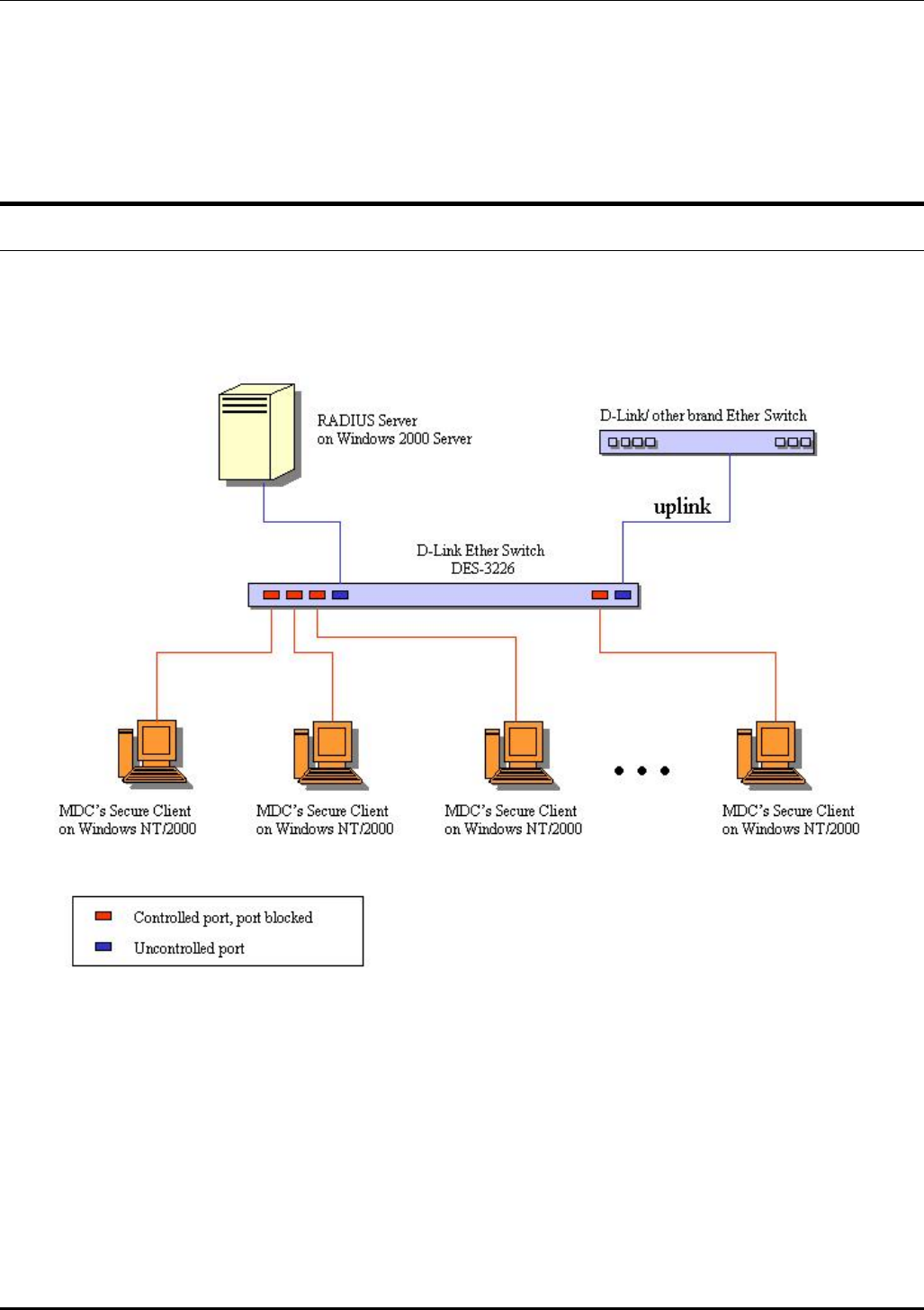
DES-3226 NWay Standalone Fast Ethernet Switch User’s Guide
Before loading TCP/IP with an address acquired from the DHCP server, DHCP clients check for an IP
address conflict by sending an Address Resolution Protocol (ARP) request containing the address. If a
conflict is found, TCP/IP does not start, and the user receives an error message. The conflicting address
should be removed for the list of active leases or it should be excluded until the conflict is identified
and resolved.
802.1X Port-based Network Access Control
The Switch is an implementation of the server side of IEEE 802.1X-Port Based Network Access Control.
Through this mechanism, users have to be authorized before being able to access the network. See the
following figure:
Figure 5-9. Typical 802.1X Configuration Prior to User Authentication
Once the user is authenticated, the switch unblocks the port that is connected to the user as shown in
the next figure.
34
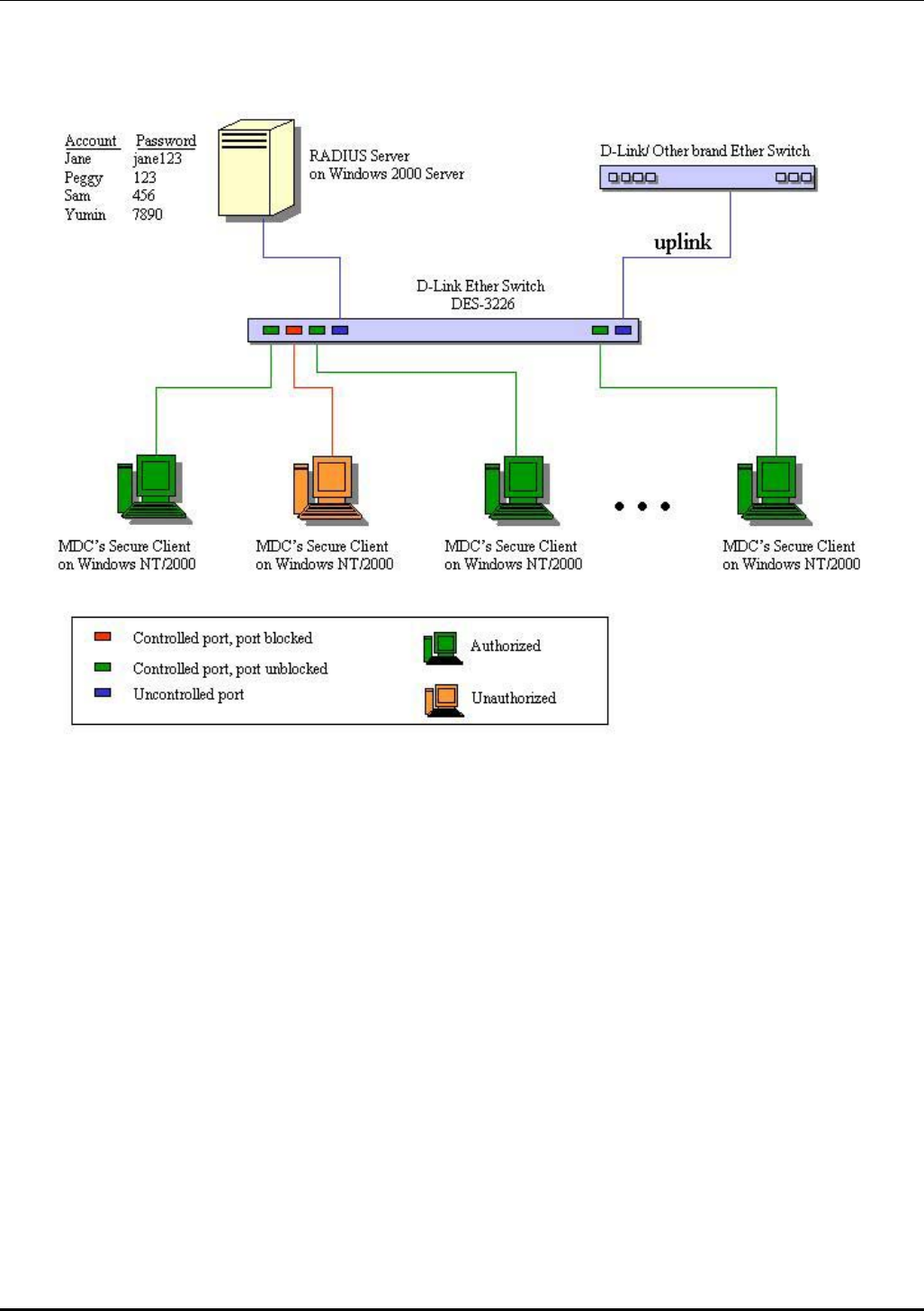
DES-3226 NWay Standalone Fast Ethernet Switch User’s Guide
Figure 5-10. Typical 802.1X Configuration with User Authentication
The user’s information, including account number, password, and configuration details such as IP
address and billing information, is stored in a centralized RADIUS server.
35
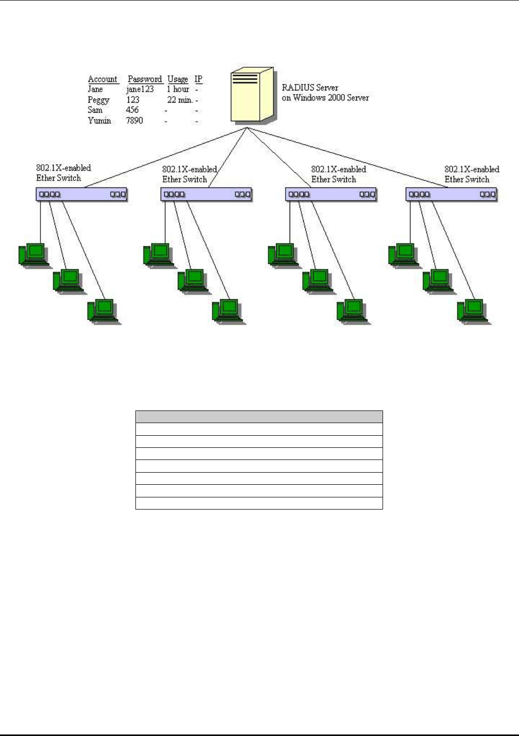
DES-3226 NWay Standalone Fast Ethernet Switch User’s Guide
Figure 5-11. Typical Configuration with 802.1X Fully Implemented
State Machine Name
Port Timers state machine
Authenticator PAE state machine
The Authenticator Key Transmit state machine
Reauthentication Timer state machine
Backend Authentication state machine
Controlled Directions state machine
The Key Receive state machine
Table 5-6. Conformance to IEEE 802.1X Standards
36

DES-3226 NWay Standalone Fast Ethernet Switch User’s Guide
6
CONFIGURING THE SWITCH USING THE
CONSOLE INTERFACE
Your Standalone Fast Ethernet Switch with one optional slide-in module supports a console
management interface that allows you to set up and control your Switch, either with an ordinary
terminal (or terminal emulator), or over the network using the TCP/IP Telnet protocol. You can use this
facility to perform many basic network management functions. In addition, the console program will
allow you to configure the Switch for management using an SNMP-based network management system.
This chapter describes how to use the console interface to access the Switch, change its settings, and
monitor its operation.
Notes are added where clarification is necessary.
Before You Start
The DES-3226 supports a wide array of functions and gives great flexibility and increased network
performance by eliminating the routing bottleneck between the WAN or Internet and the Intranet. Its
function in a network can be thought of as a new generation of router that performs routing functions
in hardware, rather than software.
This flexibility and rich feature set requires a bit of thought to arrive at a deployment strategy that will
maximize the potential of the Switch.
Connecting to the Switch
You can use the console interface by connecting the Switch to a VT100-compatible terminal or a
computer running an ordinary terminal emulator program (e.g., the terminal program included with the
Windows operating system) using an RS-232C serial cable. Your terminal parameters will need to be set
to:
• VT-100/ANSI compatible
• 9,600 baud
• 8 data bits
• No parity
• One stop bit
• No flow control
37

DES-3226 NWay Standalone Fast Ethernet Switch User’s Guide
You can also access the same functions over a Telnet interface. Once you have set an IP address for your
Switch, you can use a Telnet program (in VT-100 compatible terminal mode) to access and control the
Switch. All of the screens are identical, whether accessed from the console port or from a Telnet
interface.
Console Usage Conventions
The console interface makes use of the following conventions:
1. Items in <angle brackets> can be toggled between several choices using the space bar.
2. Items in [square brackets] can be changed by typing in a new value. You can use the backspace
and delete keys to erase characters behind and in front of the cursor.
3. The up and down arrow keys, the left and right arrow keys, the tab key and the backspace key,
can be used to move between selected items.
4. Items in UPPERCASE are commands. Moving the selection to a command and pressing Enter will
execute that command, e.g. APPLY, etc.
Please note that the command APPLY only applies for the current session. Use Save Changes from the
main menu for permanent changes. Save Changes enters the current switch configuration into non-
volatile RAM, and then reboots the Switch.
First Time Connecting to The Switch
The Switch supports user-based security that can allow you to prevent unauthorized users from
accessing the Switch or changing its settings. This section tells how to log onto the Switch.
Note: The passwords used to access the Switch are case-sensitive; therefore, “S” is not the same
as “s.”
When you first connect to the Switch, you will be presented with the first login screen (shown below).
Note: Press Ctrl+R to refresh the screen. This command can be used at any time to force the
console program in the Switch to refresh the console screen.
Figure 6-1. Initial screen, first time connecting to the Switch
Note: There is no initial username or password. Leave the Username and Password fields blank.
38
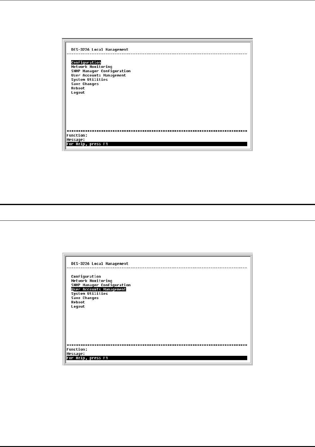
DES-3226 NWay Standalone Fast Ethernet Switch User’s Guide
Press Enter in both the Username and Password fields. You will be given access to the main menu
shown below:
Figure 6-2. Main menu
Note: The first user automatically gets Root privileges (See Table 6-1). It is recommended to create
at least one Root-level user for the Switch.
User Accounts Management
To create a new user account, highlight User Accounts Management from the main menu and press
Enter:
Figure 6-3. Main menu
39
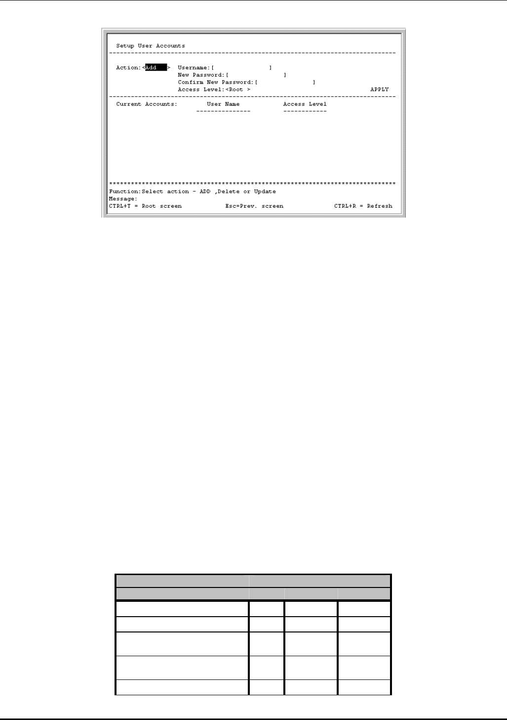
DES-3226 NWay Standalone Fast Ethernet Switch User’s Guide
Figure 6-4. Setup User Accounts screen
From the main menu, highlight User Accounts Management and press Enter, then the Setup User
Accounts screen appears.
1. Toggle the Action field to Add using the space bar. This will allow the addition of a new user. The
other options are Delete - this allows the deletion of a user entry, and Update - this allows for
changes to be made to an existing user entry.
2. Enter the new user name, assign an initial password, and then confirm the new password.
Determine whether the new user should have Root, User+, or User privileges. The space bar toggles
between the three options.
3. Highlight APPLY and press Enter to make the user addition effective.
4. Press Esc. to return to the previous screen or Ctrl+T to go to the root screen.
5. A listing of all user accounts and access levels is shown below the user setup menu. This list is
updated when APPLY is executed.
6. Please remember that APPLY makes changes to the switch configuration for the current session
only. All changes (including User additions or updates) must be entered into non-volatile ram using
the Save Changes command on the main menu - if you want these changes to be permanent.
Root, User+ and Normal User Privileges
There are three levels of user privileges: Root and User+, and User. Some menu selections available to
users with Root privileges may not be available to those with User+ and User privileges.
The following table summarizes the Root, User+ and User privileges:
Switch Configuration Privilege
Management Root User+ User
Configuration Yes Read Only Read Only
Network Monitoring Yes Read Only Read Only
Community Strings and Trap
Stations
Yes Read Only Read Only
Update Firmware and Configuration
Files
Yes No No
System Utilities Yes Ping Only Ping Only
40
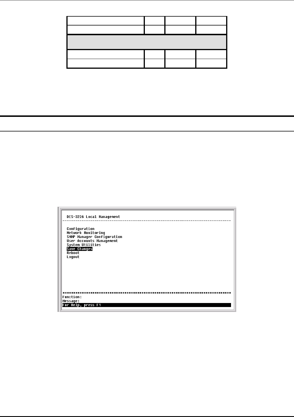
DES-3226 NWay Standalone Fast Ethernet Switch User’s Guide
Factory Reset Yes No No
Reboot Switch Yes Yes No
User Accounts Management
Add/Update/Delete User Accounts Yes No No
View User Accounts Yes No No
Table 6-1. Root, User+, and User Privileges
After establishing a User Account with Root-level privileges, press Esc. Then highlight Save Changes
and press Enter (see below). The Switch will save any changes to its non-volatile ram and reboot. You
can logon again and are now ready to continue configuring the Switch.
Save Changes
The DES-3226 has two levels of memory; normal RAM and non-volatile or NV-RAM. Configuration
changes are made effective by highlighting APPLY and pressing Enter. When this is done, the settings
will be immediately applied to the switching software in RAM, and will immediately take effect.
Some settings, though, require you to restart the Switch before they will take effect. Restarting the
Switch erases all settings in RAM and reloads the stored settings from the NV-RAM. Thus, it is
necessary to save all setting changes to NV-RAM before rebooting the Switch.
To retain any configuration changes permanently, highlight Save Changes from the main menu.
Figure 6-5. Main menu
The following screen will appear to verify that your new settings have been saved to NV-RAM:
41
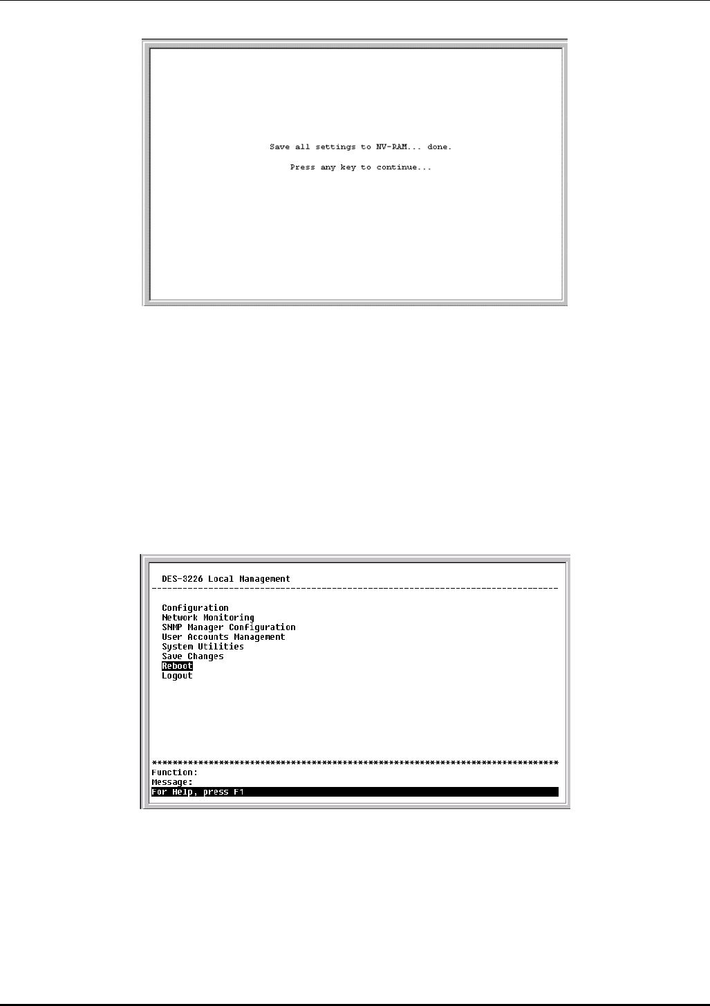
DES-3226 NWay Standalone Fast Ethernet Switch User’s Guide
Figure 6-6. Save changes screen
Once the switch configuration settings have been saved to NV-RAM, they become the default settings
for the switch. These settings will be used every time the Switch is rebooted.
Factory Reset
The only way to change the configuration stored in NV-RAM is to save a new configuration using Save
Changes, or to execute a Load Factory Default Configuration from the System Reboot menu (under
Reboot on the main menu). This will clear all settings and restore them to their initial values listed in
the appendix. These are the configuration settings entered at the factory and are the same settings
present when the Switch was purchased.
Figure 6-7. Main menu
Highlight Reboot from the main menu and press Enter.
42
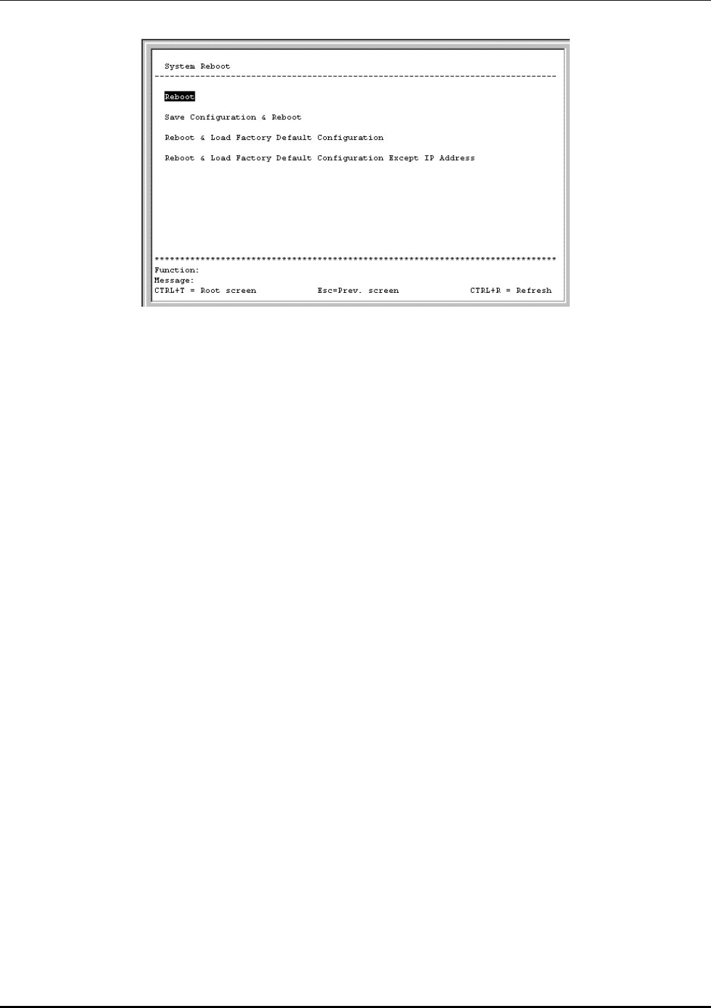
DES-3226 NWay Standalone Fast Ethernet Switch User’s Guide
Figure 6-8. System Reboot menu
Highlight the appropriate choice and press Enter to reset the Switch’s NV-RAM to the factory default settings
(or just reboot the Switch). Loading the Factory Default Configuration will erase any User Accounts (and all
other configuration settings) you may have entered and return the Switch to the state it was in when it was
purchased. The Load Factory Default Configuration Except IP Address option is used when the Switch
will be managed by the Telnet manager, which requires knowledge of the Switch’s IP address to function.
Logging Onto The Switch Console
To log in once you have created a registered user, from the Login screen:
1. Type in your Username and press Enter.
2. Type in your Password and press Enter.
3. The main menu screen will be displayed based on your access level or privilege.
Updating or Deleting User Accounts
To update or delete a user password:
Choose User Accounts Management from the main menu. The following Setup User Accounts
screen appears:
43
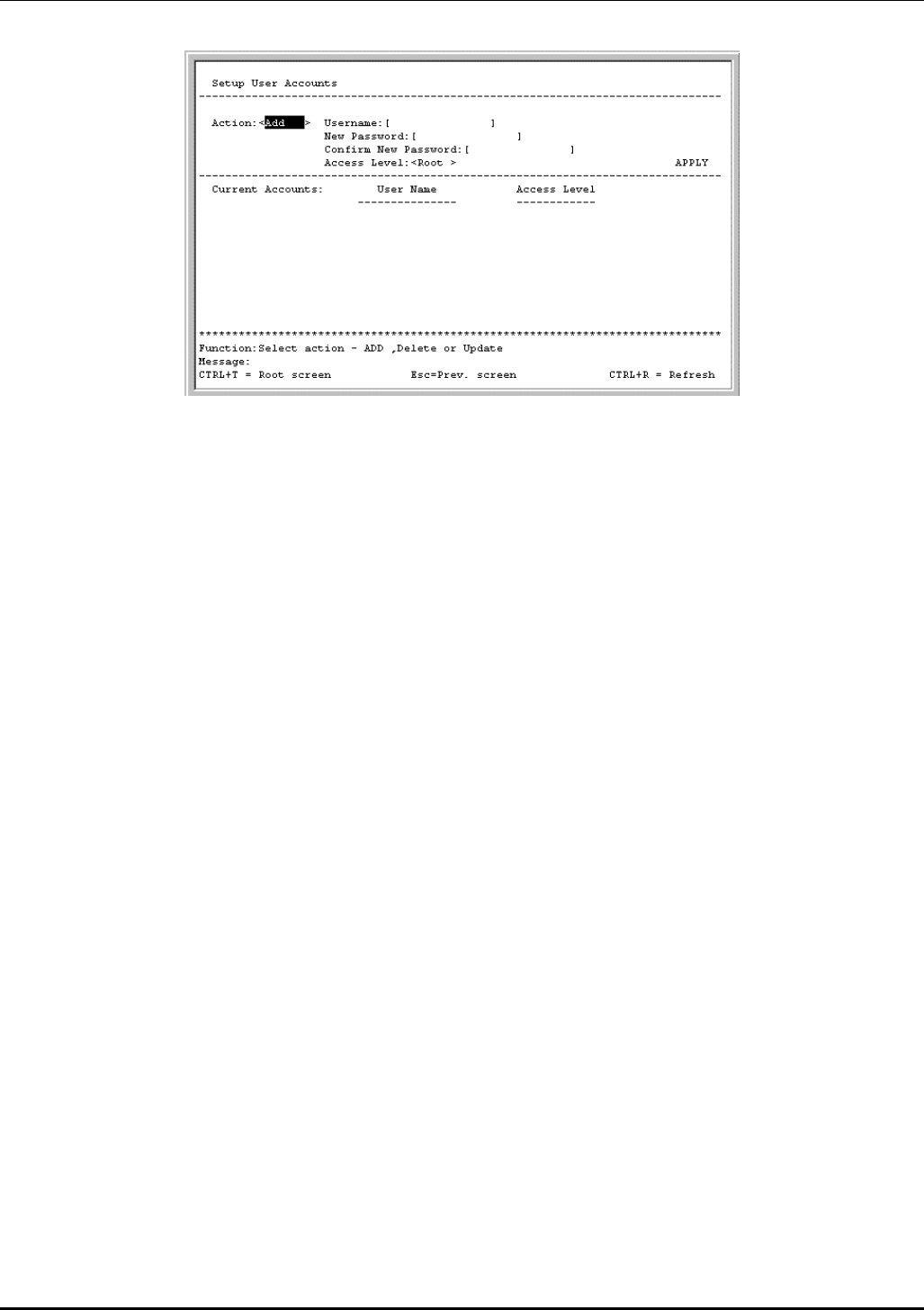
DES-3226 NWay Standalone Fast Ethernet Switch User’s Guide
Figure 6-9. Setup User Accounts screen
1. Toggle the Action field using the space bar to choose Add, Update, or Delete.
2. Type in the Username for the user account you wish to change and enter the Old Password
for that user account.
3. You can now modify the password or the privilege level for this user account.
4. If the password is to be changed, type in the New Password you have chosen, and press
Enter. Type in the same new password in the following field to verify that you have not
mistyped it.
5. If the privilege level is to be changed, toggle the Access Level field until the appropriate level
is displayed – Root, User+ or User.
6. Highlight APPLY and press Enter to make the change effective.
7. You must enter the configuration changes into the non-volatile ram (NV-RAM) using Save
Changes from the main menu if you want the configuration to be used after a switch reboot.
Only a user with Root privileges can make changes to user accounts.
Viewing Current User Accounts
Access to the console, whether using the console port or via Telnet, is controlled using a user name and
password. Up to eight user accounts can be created. The console interface will not let you delete the
current logged-in user, to prevent accidentally deleting all of the users with Root privilege.
Only users with the Root privilege can delete users.
To view the current user accounts, highlight User Accounts Management from the main menu. The
current user accounts can be read from the Setup User Accounts screen.
Deleting a User Account
1. Toggle the Action field to Delete.
2. Enter the Username and Old Password for the account you want to delete. You must enter
the password for the account to be able to delete it.
44
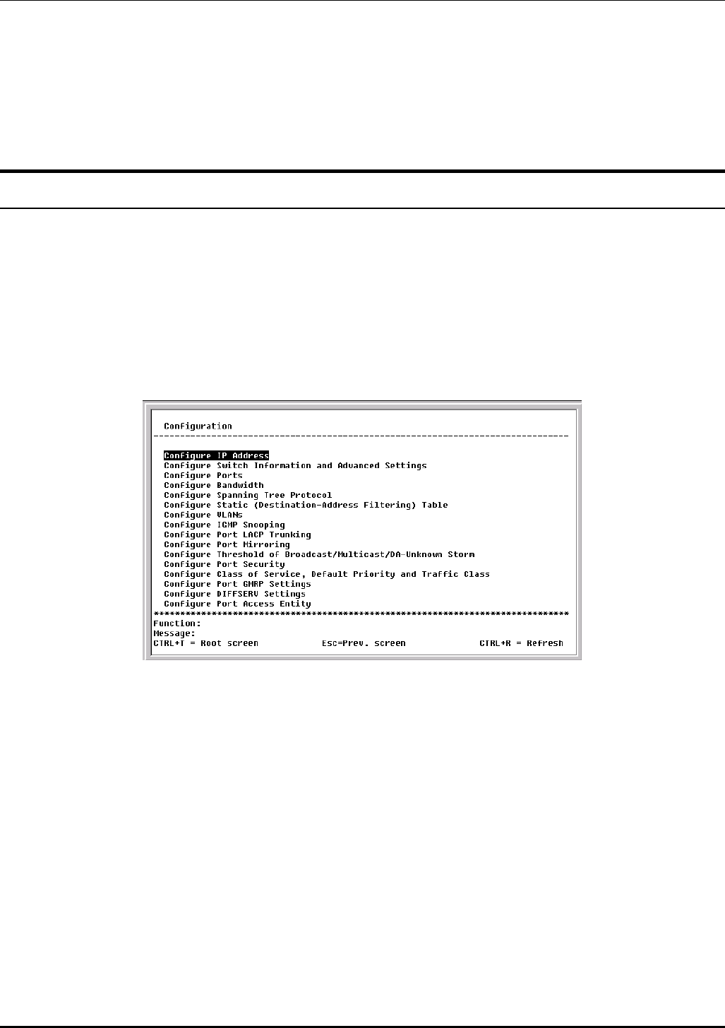
DES-3226 NWay Standalone Fast Ethernet Switch User’s Guide
3. Highlight APPLY and press Enter to make the deletion of the selected user take effect.
4. You must enter the configuration changes into the non-volatile ram (NV-RAM) using Save
Changes from the main menu if you want the configuration to be used after a switch reboot.
Only users with Root privileges can delete user accounts.
Configuration
This section will help prepare the Switch user by describing the Remote Management Setup, Switch
Information, Configure Advanced Switch Features, Configure Ports, Bandwidth Configuration,
Configure Spanning Tree, Port Spanning Tree Settings, Setup Unicast Filtering Table, Setup
Static Multicast Filtering Table, IEEE 802.1Q VLANs Configuration, 802.1Q Static VLAN Settings,
Port VLAN assignment, Ingress Filter Settings, Port GVRP Settings, IGMP Snooping Settings, Port
LACP Trunking Settings, Setup Port Mirroring, Setup Threshold of Broadcast/Multicast/DA-
Unknown Storm, Port Security Settings, Configure Class of Service, Default Priority and Traffic
Class, Port GMRP Settings, Diffserv Settings, and PAE Configuration screens, all of which can be
found under the Configuration menu, along with various submenus.
Figure 6-10. Configuration menu
Configure IP Address
Some settings must be entered to allow the Switch to be managed from an SNMP-based Network
Management System such as SNMP v1 or to be able to access the Switch using the Telnet protocol.
The Remote Management Setup screen lets you specify how the Switch will be assigned an IP address
to allow the Switch to be identified on the network.
To setup the Switch for remote management, highlight Configure IP Address from the Configuration
menu. The following screen appears:
45
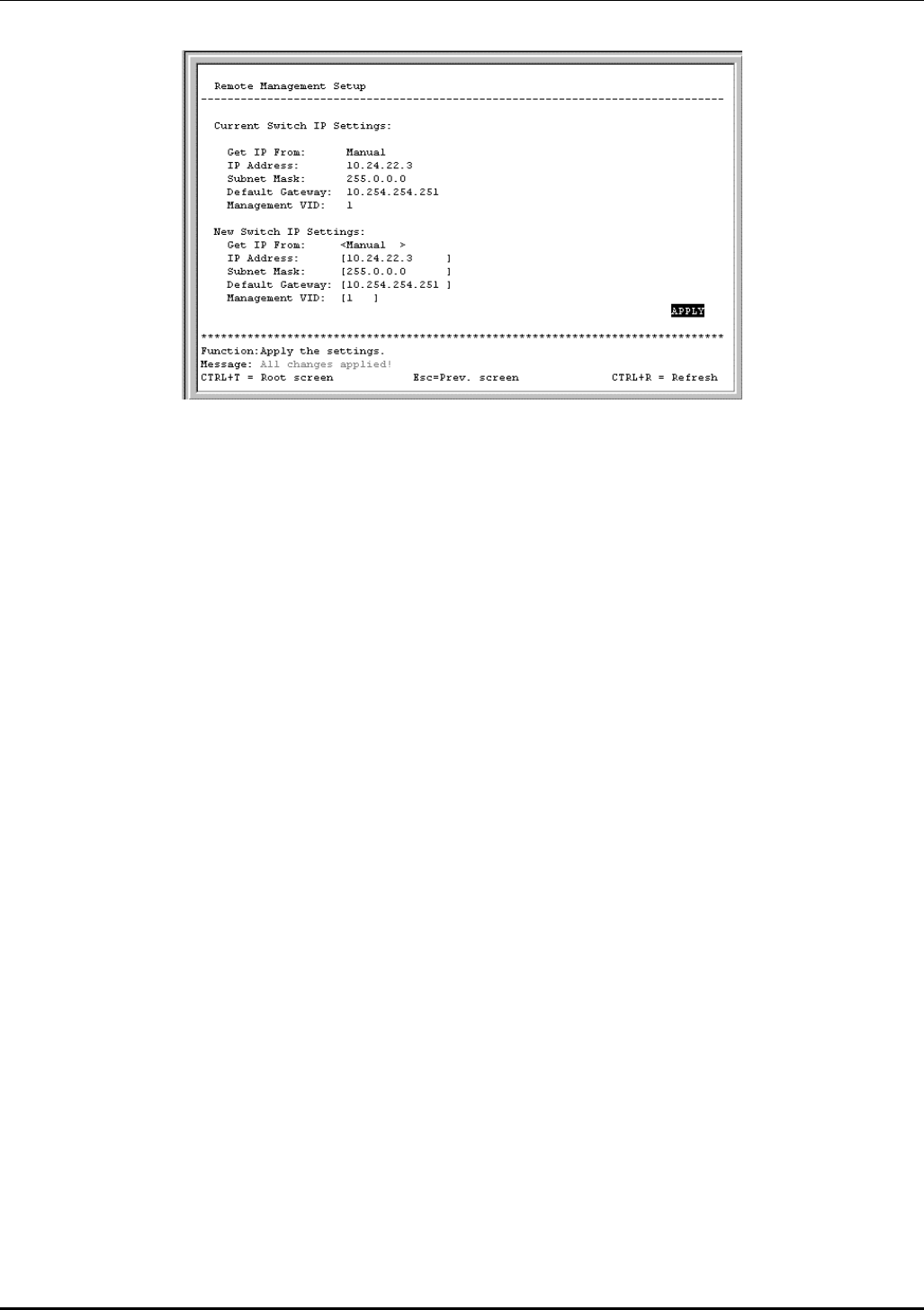
DES-3226 NWay Standalone Fast Ethernet Switch User’s Guide
Figure 6-11. Remote Management Setup screen
The Switch needs to have an IP address assigned to it so that an In-Band network management system
(e.g. Telnet) client can find it on the network. The Remote Management Setup screen allows you to
change the settings for the two different management interfaces used on the Switch: the Ethernet
interface used for in-band communication, and the SLIP interface used over the console port for out-of-
band communication.
The fields listed under the Current Switch IP Settings heading are those currently being used by the
Switch. Those fields listed under the New Switch IP Settings heading are those that will be used after
the Switch has been rebooted.
Toggle the Get IP From field using the space bar to choose from Manual, BOOTP, or DCHP. This selects
how the Switch will be assigned an IP address on the next reboot (or startup).
The Get IP From options are:
• BOOTP – The Switch will send out a BOOTP broadcast request when it is powered up. The
BOOTP protocol allows IP addresses, network masks, and default gateways to be assigned by
a central BOOTP server. If this option is set, the Switch will first look for a BOOTP server to
provide it with this information before using the default or previously entered settings.
• DCHP – The Switch will send out a DCHP broadcast request when it is powered up. The
DCHP protocol allows IP addresses, network masks, and default gateways to be assigned by a
DCHP server. If this option is set, the switch will first look for a DCHP server to provide it
with this information before using the default or previously entered settings.
• Manual – Allows the entry of an IP address, Subnet Mask, and a Default Gateway for the
Switch. These fields should be of the form xxx.xxx.xxx.xxx, where each xxx is a number
(represented in decimal form) between 0 and 255. This address should be a unique address
on the network assigned for use by the Network Administrator. The fields which require
entries under this option are as follows:
Subnet Mask – A Bitmask that determines the extent of the subnet that the Switch is on.
Should be of the form xxx.xxx.xxx.xxx, where each xxx is a number (represented in
decimal) between 0 and 255. The value should be 255.0.0.0 for a Class A network,
255.255.0.0 for a Class B network, and 255.255.255.0 for a Class C network, but custom
subnet masks are allowed.
Default Gateway – IP address that determines where packets with a destination address
outside the current subnet should be sent. This is usually the address of a router or a
46
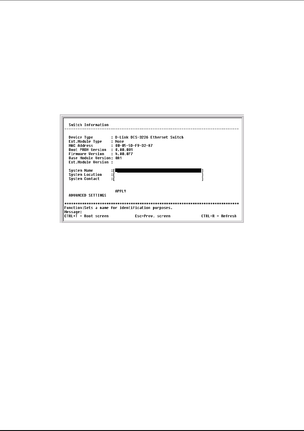
DES-3226 NWay Standalone Fast Ethernet Switch User’s Guide
host acting as an IP gateway. If your network is not part of an intranet, or you do not
want the Switch to be accessible outside your local network, you can leave this field
unchanged.
• Management VID:[ ] – Allows the entry of the VLAN ID (VID) of a VLAN that will have access
to the Telnet manager. This will be the VID of the VLAN that a management station is located
on.
Configure Switch Information and Advanced Settings
Highlight Configure Switch Information and Advanced Settings on the Configuration menu and
press Enter:
Figure 6-12. Switch Information menu
The Switch Information menu shows the type of switch, which (if any) external modules are installed,
and the Switch’s MAC Address (assigned by the factory and unchangeable). In addition, the Boot
PROM and Firmware Version numbers are shown. This information is helpful to keep track of PROM
and Firmware updates and to obtain the Switch’s MAC address for entry into another network device’s
address table – if necessary.
You can also enter the name of the System, its location, and the name and telephone number of the
System Administrator. It is recommended that the person responsible for the maintenance of the
network system that this Switch is installed on be listed here.
Configure Advanced Switch Features
Select ADVANCED SETTINGS at the bottom of the Switch Information menu and press Enter to
access the following Configure Advanced Switch Features screen:
47

DES-3226 NWay Standalone Fast Ethernet Switch User’s Guide
Figure 6-13. Configure Advanced Switch Features screen
This screen allows you to set the following features:
• Auto-Logout:<Never> – This sets the time the interface can be idle before the Switch automatically
logs-out the user. The options are 2 mins, 5 mins, 10 mins, 15 mins, or Never.
• MAC Address Aging Time (sec):[300 ] – This field specifies the length of time a learned MAC
Address will remain in the forwarding table without being accessed (that is, how long a learned MAC
Address is allowed to remain idle). The Aging Time can be set to any value between 10 and
1,000,000 seconds.
Note: A very long Aging Time can result with the out-of-date Dynamic Entries that may cause
incorrect packet filtering/forwarding decisions. A very short aging time may cause entries to
be aged out to soon, resulting in a high percentage of received packets whose source
addresses cannot be found in the address table, in which case the Switch will broadcast the
packet to all ports, negating many of the benefits of having a Switch.
• IGMP Snooping:<Disabled> – This setting enables Internet Group Management Protocol (IGMP)
Snooping, which enables the Switch to read IGMP packets being forwarded through the Switch in
order to obtain forwarding information from them (learn which ports contain Multicast members.
• Switch GVRP:<Disabled> – Group VLAN Registration Protocol is a protocol that allows members to
dynamically join VLANs. This is used to enable or disable GVRP on the Switch
• Telnet Status:<Enabled> – Toggle to Enabled to allow access to the Switch over the network using
the TCP/IP Telnet protocol.
• Web Status:<Enabled> – You can also use a Web-based browser to manage the Switch by toggling
to Enabled.
• Group Address Filter Mode:<Forward All Unregistered> – The IGMP filter mode for processing
multicast packets. The options are Forward All, Forward All Unregistered, and Filtered All
Unregistered.
• Scheduling Mechanism for CoS Queues:<Strict> – There are two Class of Service queue options,
RoundRobin and Strict. If Strict is selected, when the highest priority queue is full, those packets will
be the first to be forwarded. If RoundRobin is selected, the forwarding is based on the settings made
on the Class of Service Configuration screen.
48
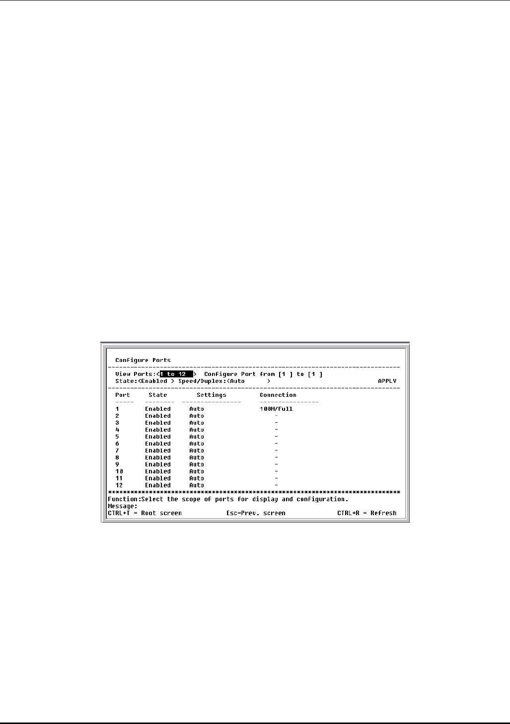
DES-3226 NWay Standalone Fast Ethernet Switch User’s Guide
• Trunk Load Sharing Algorithm:<Src Address> – The trunk load sharing options are Dst Address,
Src&Dst Address, and Src Address.
• Backpressure:<Disabled> – This allows you to enable or disable the backpressure function for the
Switch.
• Switch GMRP:<Disabled> – Group Multicast Registration Protocol is a protocol that allows
members to dynamically join Multicast groups. GMRP must also be enabled on specific ports on the
Port GMRP Settings screen for it to take effect. This global control is especially useful if you want
to turn off GMRP on the whole Switch without making changes to each individual port.
• Switch 802.1X:<Disabled> – Set the 802.1X access control by toggling between Enabled and
Disabled.
• Switch Filtering EAPOL PDU:<Yes> – This option is only available if 802.1X is disabled. It filters
Extensible Authentication Protocol Over LANs Packet Data Units (EAPOL PDU) when enabled.
• Switch Traffic Segmentation:<Disabled> – When this feature is Enabled, ports on the Switch are
not able to communicate with one another. If there is not an optional module present, Port 1
becomes the server port. If there is a 1-port optional module, this port will be the server port. If
there is a 2-port optional module, both ports act as server ports.
Configure Ports
Highlight Configure Ports from the Configuration menu and press Enter:
Figure 6-14. Configure Ports screen
Toggle the View Ports field, using the space bar, to view the configuration of either ports 1 through 12
or ports 13 through 24. To configure a specific port, toggle the Configure Port from [ ] to [ ] field until
the appropriate port number or port range appears.
Toggle the State field to either enable or disable a given port.
Toggle the Speed/Duplex field to select the speed and duplex/half-duplex state of the port. Auto means
auto-negotiation between 10 and 100 Mbps devices, in full- or half-duplex mode. The Auto setting
allows the port to automatically determine the fastest settings the device the port is connected to can
handle, and then to use those settings. The other options are 100M/Full, 100M/Half, 10M/Full, and
10M/Half. There is no automatic adjustment of port settings with any option other than Auto.
49
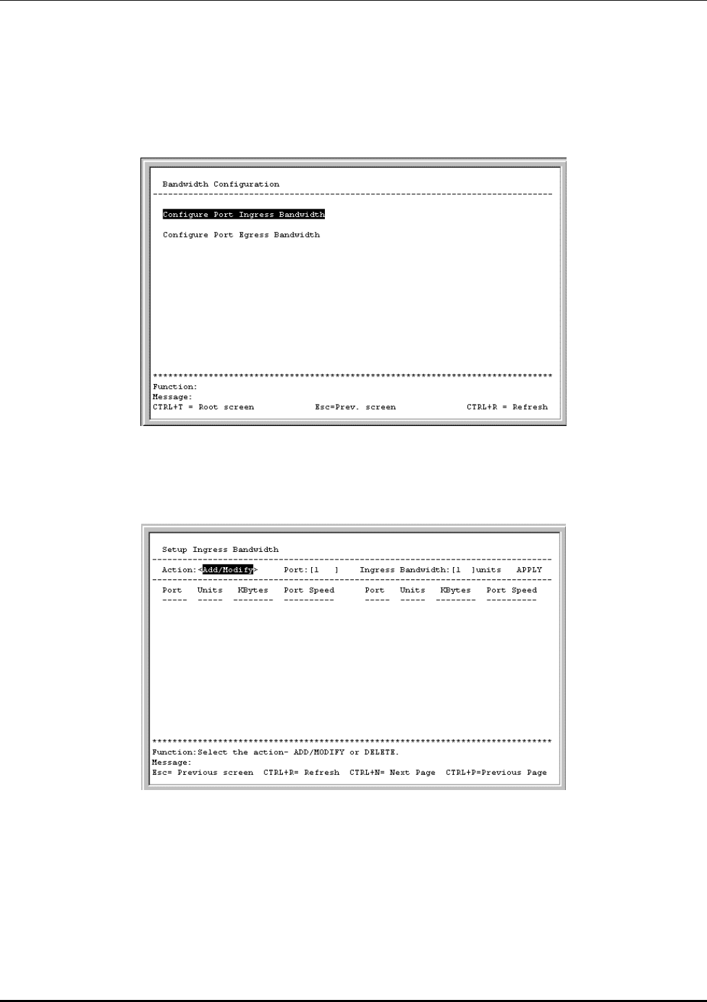
DES-3226 NWay Standalone Fast Ethernet Switch User’s Guide
Configure Bandwidth
The Bandwidth Configuration menu allows you to access screens that set and display the Ingress
bandwidth and Egress bandwidth of specified ports on the Switch.
Highlight Configure Bandwidth on the Configuration menu and press Enter:
Figure 6-15. Bandwidth Configuration menu
To configure port ingress bandwidth, highlight Configure Port Ingress Bandwidth on the screen above
and click Enter:
Figure 6-16. Setup Ingress Bandwidth screen
To configure ingress bandwidth for a specific port, select Add/Modify in the first field, specify a port in
the next field, and then enter a bandwidth between 1 and 127. Press APPLY to let your changes take
effect. To delete an entry, toggle the Action field to Delete.
To configure port egress bandwidth, highlight Configure Port Egress Bandwidth on the Bandwidth
Configuration screen and click Enter:
50
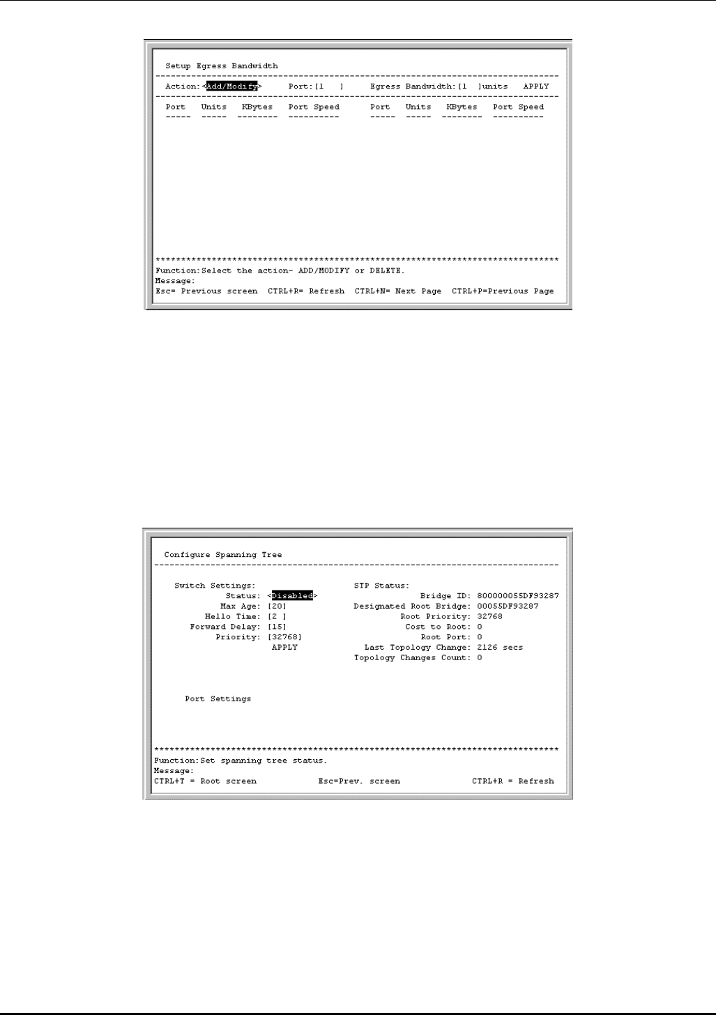
DES-3226 NWay Standalone Fast Ethernet Switch User’s Guide
Figure 6-17. Setup Egress Bandwidth screen
To configure egress bandwidth for a specific port, select Add/Modify in the first field and specify a port
in the next field. Next, enter a bandwidth between 1 and 127 in the last field. Finally, press APPLY and
save the changes. To delete an entry, toggle the Action field to Delete.
Configure Spanning Tree Protocol
To globally configure STP on the Switch, highlight Configure Spanning Tree Protocol on the
Configuration menu and press Enter:
Figure 6-18. Configure Spanning Tree menu
The Spanning Tree Protocol (STP) operates on two levels: on the switch level, the settings are globally
implemented. On the port level, the settings are implemented on a per user-defined group basis.
Note: The factory default settings should cover the majority of installations. Therefore, it is
advisable to keep the default settings as set at the factory unless it is absolutely necessary
to change them.
The user-changeable parameters in the Switch are as follows:
51
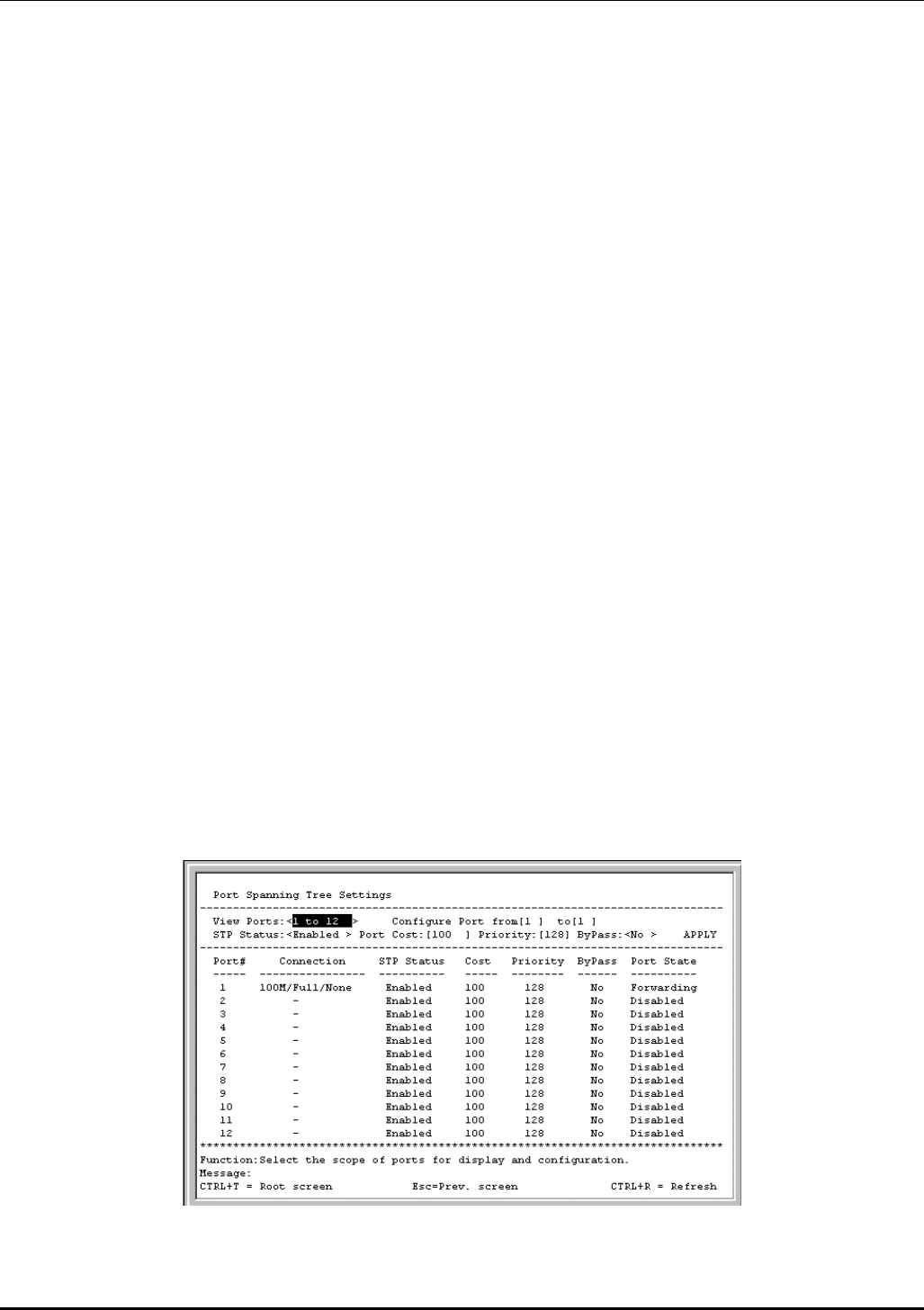
DES-3226 NWay Standalone Fast Ethernet Switch User’s Guide
• Status:<Disabled> – Toggle to Enabled to implement the Spanning Tree Protocol on the
Switch.
• Max Age: [20] – The Maximum Age can be set from 6 to 40 seconds. At the end of the Max
Age, if a BPDU has still not been received from the Root Bridge, your Switch will start sending
its own BPDU to all other Switches for permission to become the Root Bridge. If it turns out
that your Switch has the lowest Bridge Identifier, it will become the Root Bridge.
• Hello Time: [2 ] – The Hello Time can be set from 1 to 10 seconds. This is the interval
between two transmissions of BPDU packets sent by the Root Bridge to tell all other Switches
that it is indeed the Root Bridge. If you set a Hello Time for your Switch, and it is not the Root
Bridge, the set Hello Time will be used if and when your Switch becomes the Root Bridge.
Note: The Hello Time cannot be longer than the Max. Age. Otherwise, a configuration error will
occur.
• Forward Delay: [15] – The Forward Delay can be from 4 to 30 seconds. This is the time any
port on the Switch spends in the listening state while moving from the blocking state to the
forwarding state.
• Priority: [32768] – A Priority for the switch can be set from 0 to 65535. 0 is equal to the
highest Priority. This number is used in the voting process between switches on the network
to determine which switch will be the root switch. A low number indicates a high priority, and
a high probability that this switch will be elected as the root switch.
Note: Observe the following formulas when setting the above parameters:
Max. Age ≤ 2 x (Forward Delay - 1 second)
Max. Age ≥ 2 x (Hello Time + 1 second)
Port Spanning Tree Settings
In addition to setting Spanning Tree parameters for use on the switch level, the Switch allows for the
configuration of Spanning Tree Protocol on individual ports.
To define individual ports, highlight Port Settings on the Configure Spanning Tree menu above and
press Enter.
Figure 6-19. Port Spanning Tree Settings screen
52
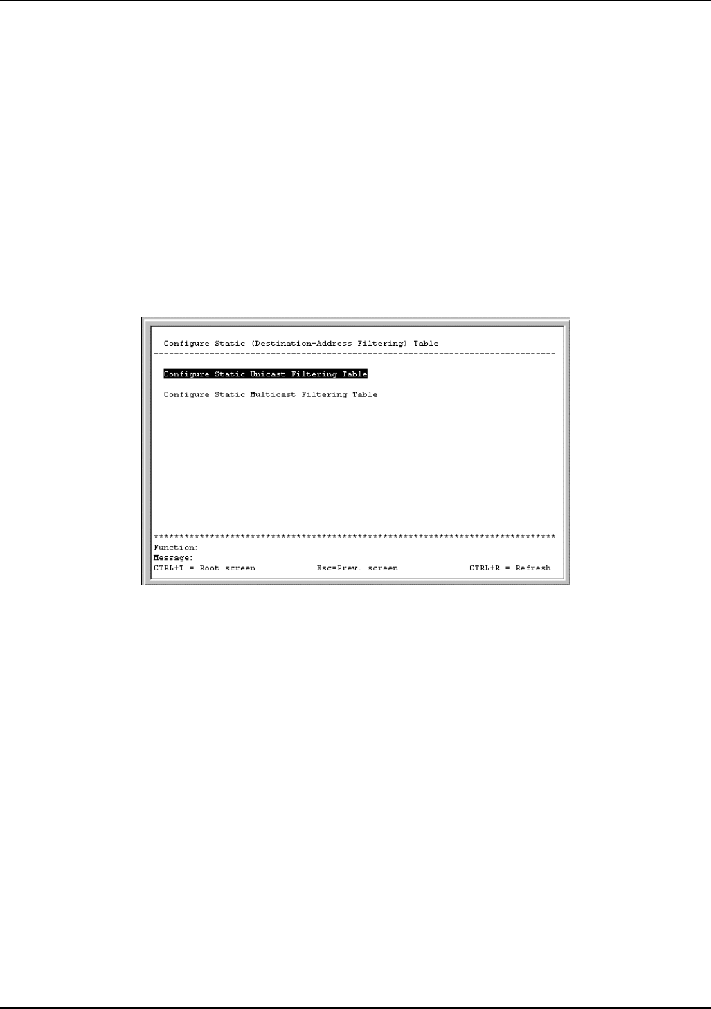
DES-3226 NWay Standalone Fast Ethernet Switch User’s Guide
Toggle the View Ports field to the range of ports to be configured. The Fast Ethernet ports displayed for
configuration in groups of 12 and the optional 100BASE ports are displayed together—if a 2-port rather
than 1-port extension module is installed. Enter the port number or port range in the Configure Port
from [ ] to [ ] field. After enabling or disabling STP Status, you can set the spanning tree port cost
and priority. Toggle the Bypass field to Yes if you want to enable the Switch to skip the usual waiting
time associated with the listening state.
Configure Static (Destination-Address Filtering) Table
The Configure Static (Destination-Address Filtering) Table menu allows you to access screens to
create, modify, and delete both Static Unicast Filtering Table and Static Multicast Filtering Table
entries, respectively.
Highlight Configure Static (Destination-Address Filtering) Table on the Configuration menu and
press Enter:
Figure 6-20. Configure Static (Destination-Address Filtering) Table menu
Setup Unicast Filtering Table
Highlight Configure Static Unicast Filtering Table on the menu above to access the following screen:
53
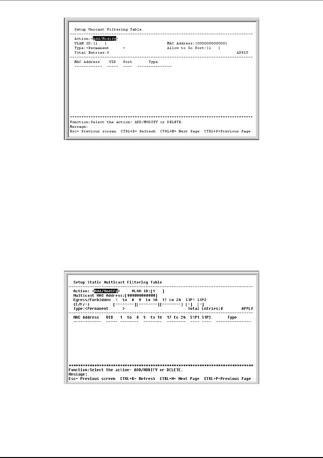
DES-3226 NWay Standalone Fast Ethernet Switch User’s Guide
Figure 6-21. Setup Unicast Filtering Table screen
The Action field can be toggled between Add/Modify and Delete using the space bar. Enter the VID in
the VLAN ID field and the MAC address to be statically entered in the forwarding table in the MAC
Address field. There are two static unicast filter types to select from, Permanent and DeleteOnReset.
Enter the port number in the Allow to Go Port field.
Highlight APPLY and press Enter to make the changes current. Use Save Changes from the main
menu to enter the changes into NV-RAM.
Setup Static Multicast Filtering Table
To edit the IEEE 802.1q Multicast Filtering settings, highlight Configure Static Multicast Filtering
Table on the Configure Static (Destination-Address Filtering) Table menu above to access the
following screen:
Figure 6-22. Setup Static Multicast Filtering Table screen
The Action field can be toggled between Add/Modify and Delete using the space bar. To add a new
entry to the static multicast filtering table, select Add/Modify and enter the VLAN ID number of the
VLAN that will be receiving the multicast packets. Enter the MAC address of the multicast source, and
then enter the member ports. Each port can be Egress, Forbidden, or a non-member of the multicast
54

DES-3226 NWay Standalone Fast Ethernet Switch User’s Guide
group, on a per-VLAN basis. There are two static multicast filter types to select from, Permanent and
DeleteOnReset.
To set a port’s multicast group membership status, highlight the first field of (E/F/-). Each port’s
multicast group membership can be set individually by highlighting the port’s entry using the arrow
keys, and then toggling among E, F, and – using the space bar.
• E (Egress Member) – Specifies the port as being a static member of the multicast group.
Egress Member Ports are ports that will be transmitting traffic for the multicast group.
• F (Forbidden Member) – Specifies the port as being forbidden from joining a VLAN
dynamically.
• – (Non-Member) – Specifies the port as not being a member of the multicast group, but the
port can become a member of the multicast group dynamically.
Highlight APPLY and press Enter to make the changes current. Use Save Changes from the main
menu to enter the changes into NV-RAM.
Configure VLANs
The Switch reserves one VLAN, VID = 1, called the DEFAULT_VLAN for internal use. The factory default
setting assigns all ports on the Switch to the DEFAULT_VLAN. As new VLANs are configured, their
respective member ports are removed from the DEFAULT_VLAN. If the DEFAULT_VLAN is reconfigured,
all ports are again assigned to it. Ports that are not wanted as part of the DEFAULT_VLAN are removed
during the configuration.
Packets cannot cross VLANs. If a member of one VLAN wants to connect to another VLAN, it must be
through a router.
Note: The Switch’s default is to assign all ports to a single 802.1Q VLAN named
DEFAULT_VLAN. As new VLANs are created, the member ports assigned to the new VLAN
will be removed from the default VLAN port member list.
Note: The DEFAULT_VLAN has a VID = 1. An IP interface called System in the IP interface entry
menu also has a VID = 1, and therefore corresponds to the DEFAULT_VLAN.
To create a new 802.1Q VLAN:
The VLAN menu adds an entry to edit the VLAN definitions and to configure the port settings for IEEE
802.1Q VLAN support. Highlight Configure VLANs from the Configuration menu and press Enter.
55
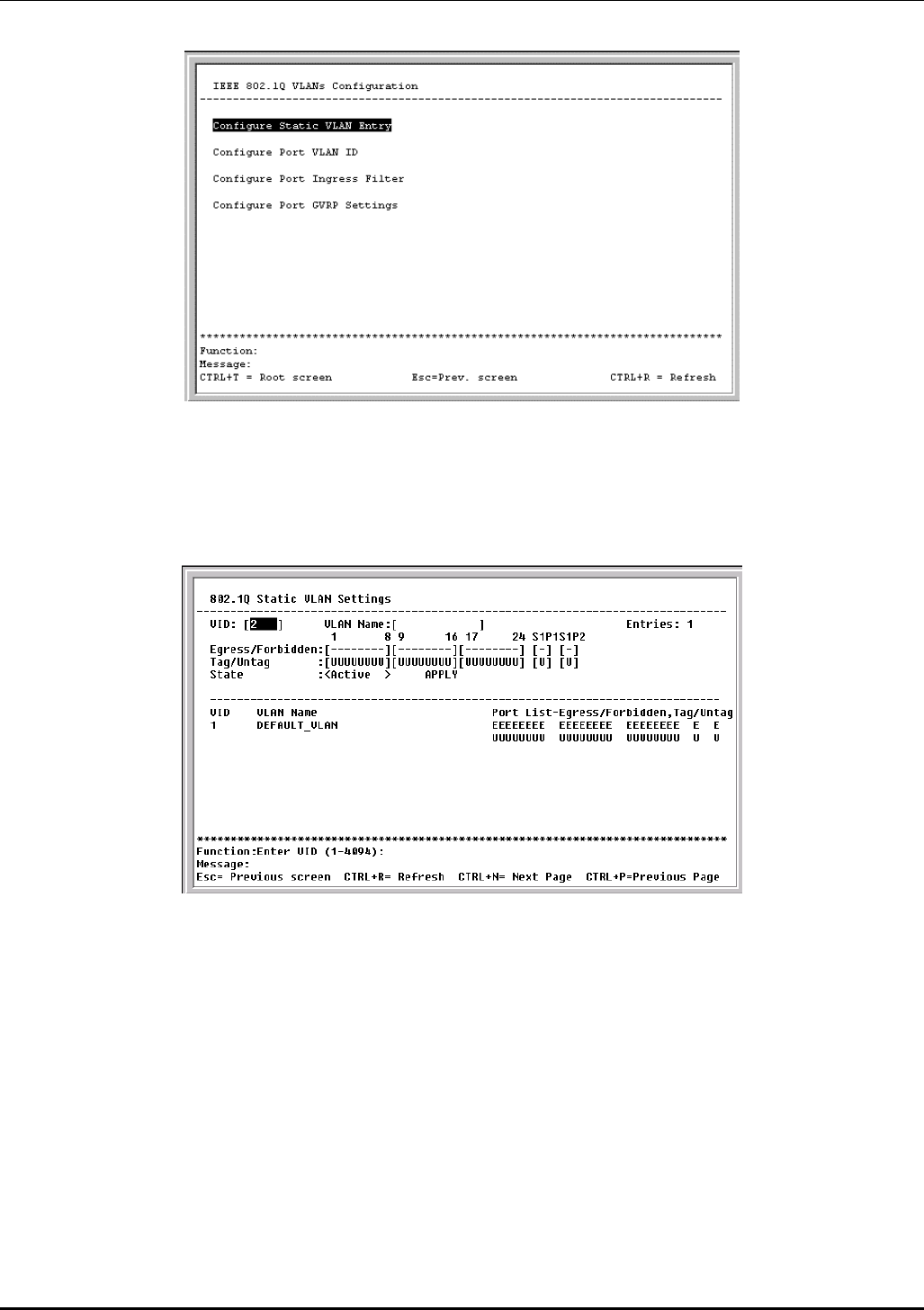
DES-3226 NWay Standalone Fast Ethernet Switch User’s Guide
Figure 6-23. IEEE 802.1Q VLANs Configuration menu
802.1Q Static VLAN Settings
To create an 802.1Q VLAN, highlight Configure Static VLAN Entry and press Enter:
Figure 6-24. 802.1Q Static VLAN Settings screen
To create an 802.1Q VLAN, enter a VLAN ID number in the VID field and a name for the new VLAN in
the VLAN Name field.
To set the 802.1Q VLAN membership status of a port:
To enter the 802.1Q VLAN status for a port, highlight the first field of Egress/Forbidden. Each port’s
802.1Q VLAN membership can be set individually by highlighting the port’s entry using the arrow keys,
and then toggling between E and – using the space bar.
• E (Egress Member) – Specifies the port as being a static member of the VLAN. Egress
Member Ports are ports that will be transmitting traffic for the VLAN. These ports can be
either tagged or untagged.
• F (Forbidden Non-Member) – Defines the port as a non-member and also forbids the port
from joining a VLAN dynamically.
56
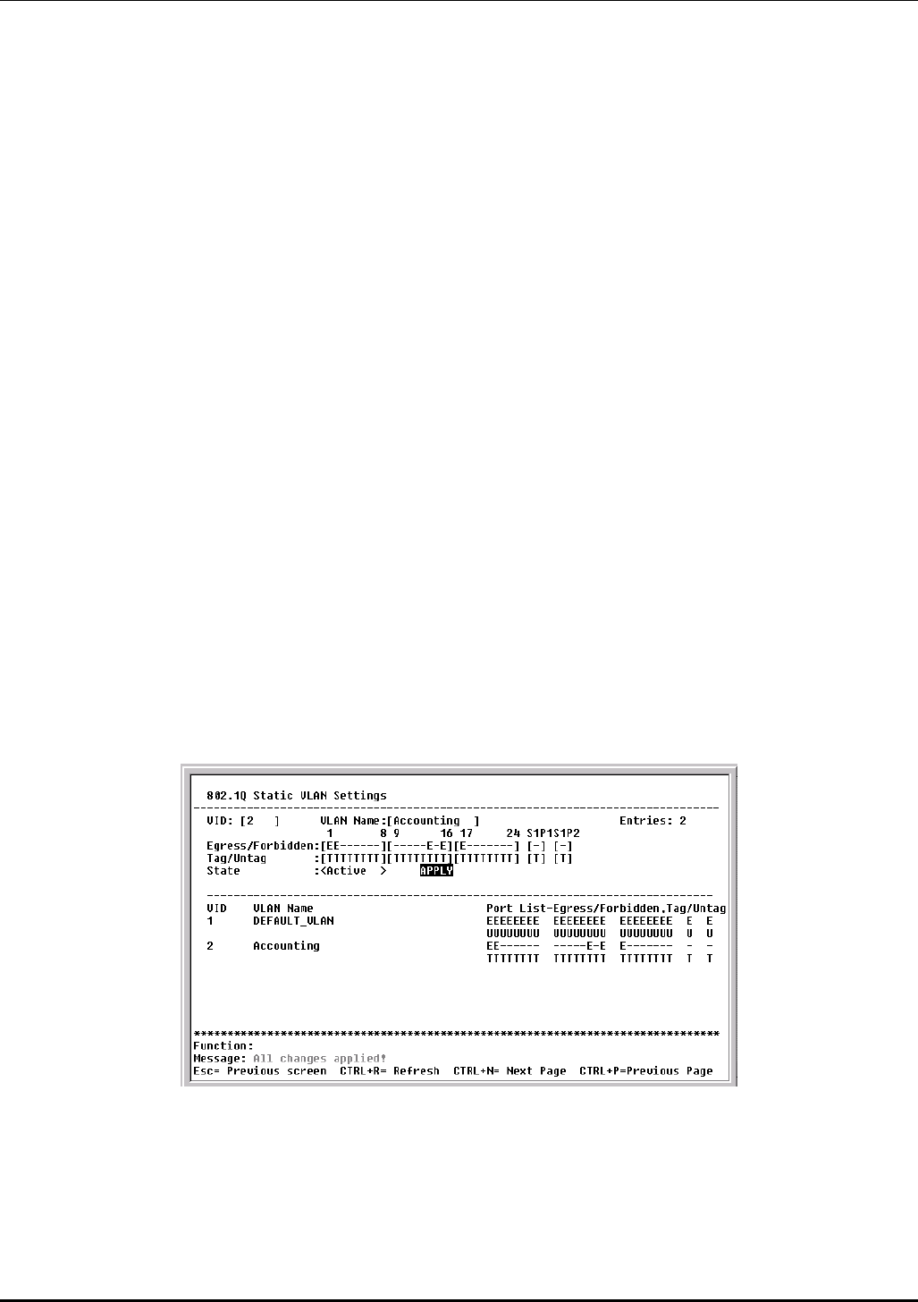
DES-3226 NWay Standalone Fast Ethernet Switch User’s Guide
• – (Non-Member) – Specifies the port as not being a member of the VLAN, but the port can
become a member of the VLAN dynamically.
Next, determine which of the ports that are members of the new VLAN will be Tagged or Untagged
ports.
To set a port as either a Tagged or an Untagged port:
Highlight the first field of Tag/Untag field. Each port’s state can be set by highlighting the port’s entry
using the arrow keys and then toggling between U or T using the space bar.
• U - specifies the port as an Untagged member of the VLAN. When an untagged packet is
transmitted by the port, the packet header remains unchanged. When a tagged packet exits
the port, the tag is stripped and the packet is changed to an untagged packet.
• T - specifies the port as a Tagged member of the VLAN. When an untagged packet is
transmitted by the port, the packet header is changed to include the 32-bit tag associated
with the PVID (Port VLAN Identifier – see below). When a tagged packet exits the port, the
packet header is unchanged.
If the port is attached to a device that is not IEEE 802.1Q VLAN compliant (VLAN-tag unaware), then
the port should be set to U – Untagged.
If the port is attached to a device that is IEEE 802.1Q VLAN compliant, (VLAN-tag aware), then the port
should be set to T – Tagged.
Once you have toggled between Active and Inactive under State, press APPLY to make the additions or
deletions effective for the current session. To enter the changes into Non-volatile RAM, highlight Save
Changes from the main menu and press Enter.
In the following example screen, the VLAN “Accounting” – VID # 2 – has been added. Ports 1, 2, 14, 16,
and 17 are Egress ports (static members of “Accounting”).
Example of 802.1Q VLAN:
Figure 6-25. 802.1Q Static VLAN Settings screen
Port VLAN assignment
To assign a port a PVID, highlight Configure Port VLAN ID on the IEEE 802.1Q VLANs Configuration
menu and press Enter:
57
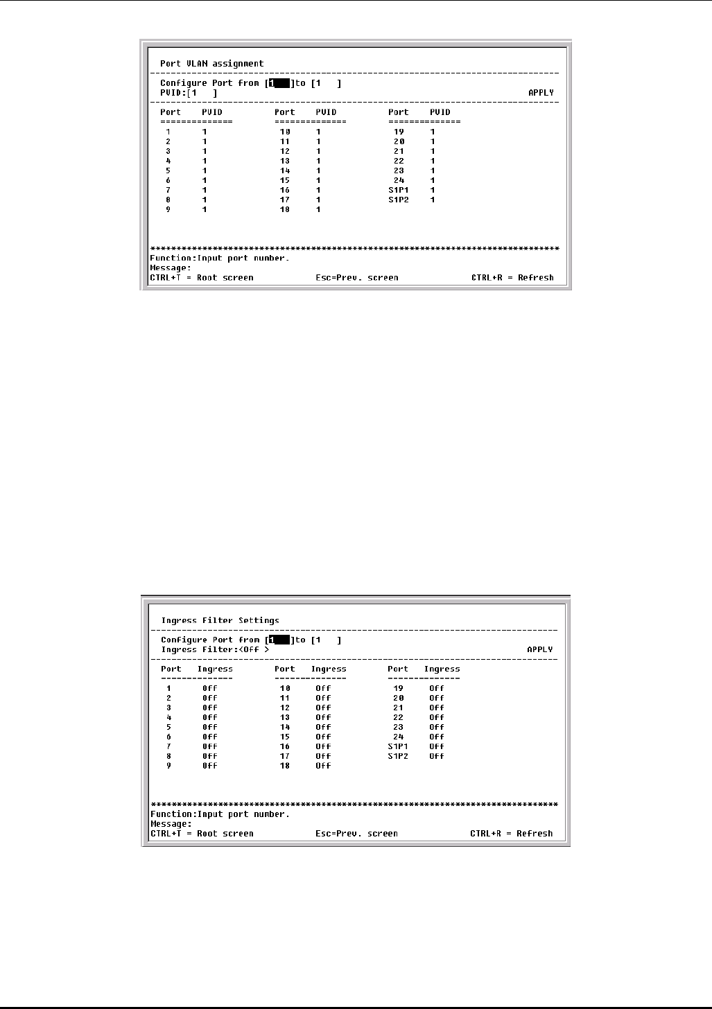
DES-3226 NWay Standalone Fast Ethernet Switch User’s Guide
Figure 6-26. Port VLAN assignment screen
Highlight the Configure Port from [1 ] to [1 ] field and enter the range of port numbers you want to
configure. Next, highlight the PVID field and enter the PVID for the VLAN’s member ports you want to
configure.
Port VLAN Identifier (PVID) is a classification mechanism that associates a port with a specific VLAN
and is used to make forwarding decisions for untagged packets received by the port. For example, if
port #2 is assigned a PVID of 3, then all untagged packets received on port #2 will be assigned to VLAN
3. This number is generally the same as the VID# number assigned to the port in the 802.1Q Static
VLAN Settings screen above.
Ingress Filter Settings
To set ingress filtering on a port, highlight Configure Port Ingress Filter on the IEEE 802.1Q VLANs
Configuration menu and press Enter:
Figure 6-27. Ingress Filter Settings screen
Highlight the Configure Port from [1 ] to [1 ] field and enter the range of port numbers you want to
configure. Then use the space bar to toggle between On and Off in the Ingress Filter field.
An Ingress Filter enables the port to compare the VID tag of an incoming packet with the PVID number
assigned to the port. If the two are different, the port filters (drops) the packet.
58
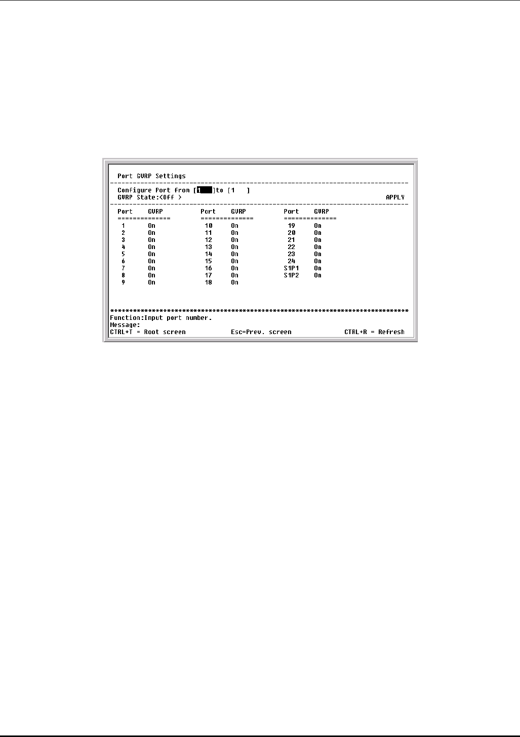
DES-3226 NWay Standalone Fast Ethernet Switch User’s Guide
Port GVRP Settings
GARP VLAN Registration Protocol (GVRP) is a Generic Attribute Registration Protocol (GARP) application
that provides 802.1Q-compliant VLAN pruning and dynamic VLAN creation on 802.1Q trunk ports.
With GVRP, the Switch can exchange VLAN configuration information with other GVRP switches, prune
unnecessary broadcast and unknown unicast traffic, and dynamically create and manage VLANs on
switches connected through 802.1Q trunk ports.
To enable a port to dynamically become a member of a VLAN, highlight Configure Port GVRP Settings
on the IEEE 802.1Q VLANs Configuration menu and press Enter:
Figure 6-28. Port GVRP Settings screen
This screen allows you to enable or disable GARP VLAN Registration Protocol (GVRP), where GARP is
the Generic Attribute Registration Protocol, on individual ports. Enter the range of ports to be
configured in the first two fields and then toggle the GVRP State to On. Press APPLY to let your changes
take effect.
GVRP updates dynamic VLAN registration entries and communicates the new VLAN information across
the network. This allows, among other things, for stations to physically move to other switch ports and
keep their same VLAN settings, without having to reconfigure VLAN settings on the Switch.
Configure IGMP Snooping
IGMP Snooping can be globally enabled or disabled from the IGMP Snooping Settings screen.
To configure IGMP Snooping, highlight Configure IGMP Snooping on the Configuration menu and
press Enter.
59
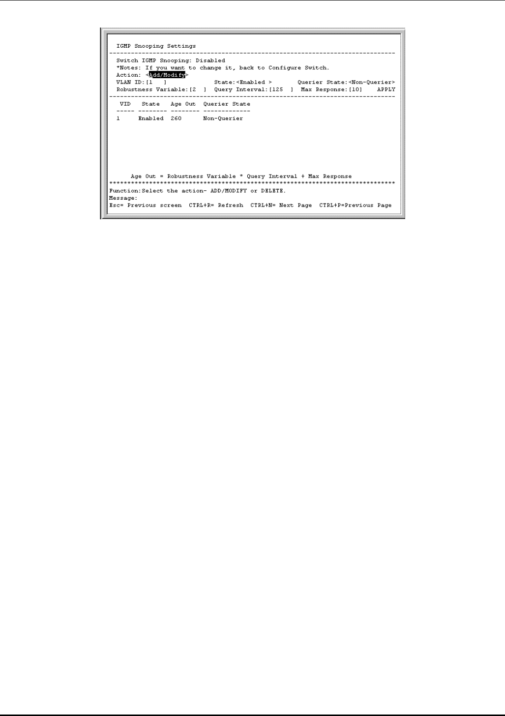
DES-3226 NWay Standalone Fast Ethernet Switch User’s Guide
Figure 6-29. IGMP Snooping Settings screen
To configure IGMP Snooping:
Toggle the Switch IGMP Snooping field to Enabled. Toggle the Querier State field to the appropriate
choice between Non-Querier, V1-Querier, and V2-Querier to determine the version of IGMP that is used
in your network. A value between 1 and 255 can be entered for the Robustness Variable (default is 2).
The Query Interval can be set between 1 and 65535 seconds (default is 125 seconds). This sets the
time between IGMP queries. The Max Response allows a setting between 1 and 25 seconds (default is
10) and specifies the maximum amount of time allowed before sending a response report.
Highlight APPLY and press Enter to make the settings effective.
The user-changeable parameters in the Switch are as follows:
• Switch IGMP Snooping:<Disabled> – This field can be toggled using the space bar between
Disabled and Enabled. This is used to enable or disable IGMP Snooping, globally, on the Switch.
• Action:<Add/Modify> – Toggle to the desired option, Add/Modify or Delete.
• VLAN ID:[1] – Enter the appropriate VLAN ID in this field.
• State:<Enabled> – Toggle this field to Enabled to activate this entry.
• Querier State:<Non-Querier> – This field can be toggled between Non-Querier, V1-Querier, and V2-
Querier. This is used to specify the IGMP version (1 or 2) that will be used by the IGMP interface
when making queries.
• Robustness Variable:[2 ] – A tuning variable to allow for sub-networks that are expected to lose a
large number of packets. A value between 1 and 255 can be entered, with larger values being
specified for sub-networks that are expected to lose larger numbers of packets.
• Query Interval:[125 ] – Allows the entry of a value between 1 and 65535 seconds, with a default of
125 seconds. This specifies the length of time between sending IGMP queries.
• Max Response:[10] – Sets the maximum amount of time allowed before sending an IGMP response
report. A value between 1 and 25 seconds can be entered, with a default of 10 seconds.
60
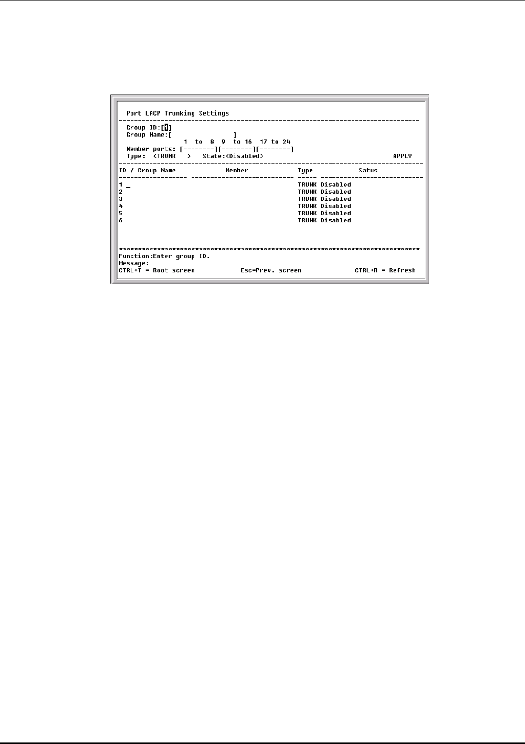
DES-3226 NWay Standalone Fast Ethernet Switch User’s Guide
Configure Port LACP Trunking
To configure a port trunking group, highlight Configure Port Trunking on the Configuration menu
and press Enter.
Figure 6-30. Port LACP Trunking Settings screen
Port trunking allows several ports to be grouped together and to act as a single link. This gives a
bandwidth that is a multiple of a single link’s bandwidth.
Port trunking is most commonly used to link a bandwidth intensive network device or devices – such as
a server – to the backbone of a network.
The Switch allows the creation of up to 6 port trunking groups, each group consisting of up to 8 links
(ports). The trunked ports can be non-continuous (that is, have non-sequential port numbers). All of
the ports in the group must be members of the same VLAN. Further, the trunked ports must all be of
the same speed and should be configured as full duplex.
The configuration of the lowest numbered port in the group becomes the configuration for all of the
ports in the port trunking group. This port is called the Master Port of the group, and all configuration
options – including the VLAN configuration – that can be applied to the Master Port are applied to the
entire port trunking group.
Load balancing is automatically applied to the ports in the trunked group, and a link failure within the
group causes the network traffic to be directed to the remaining links in the group.
The Spanning Tree Protocol will treat a port trunking group as a single link, on the switch level. On the
port level, the STP will use the port parameters of the Master Port in the calculation of port cost and in
determining the state of the port trunking group. If two redundant port trunking groups are configured
on the Switch, STP will block one entire group – in the same way STP will block a single port that has a
redundant link.
The Link Aggregate Control Protocol (LACP) allows you to bundle several physical ports together to form
one logical port. In contrast to traditional port trunking as explained above, LACP trunking requires
every member port to use the same protocol. If, for example, one member port on a switch does not
support LACP, then that port cannot be a member of the port trunking group.
The user-changeable parameters in the Switch are as follows:
• Group ID:[1] – This field is for a group ID number for the port trunking group.
61
DES-3226 NWay Standalone Fast Ethernet Switch User’s Guide
• Group Name:[ ] – Enter a name for the port trunking group.
• Member ports:[ ][ ] [ ] – Toggle between M to indicate membership of the port trunking group, or a
dash (–) to indicate non-membership.
• Type:<TRUNK> – Toggle between TRUNK and LACP. If LACP is selected, each member of the port
trunking group must support the Link Aggregate Control Protocol. There is no protocol requirement
if TRUNK is selected.
• State:<Disabled> – This field can be toggled between Enabled and Disabled. This is used to turn a
port trunking group on or off. This is useful for diagnostics, to quickly isolate a bandwidth intensive
network device or to have an absolute backup aggregation group that is not under automatic
control.
Configure Port Mirroring
The Switch allows you to copy frames transmitted and received on a port and redirect the copies to
another port. You can attach a monitoring device to the mirrored port, such as a sniffer or an RMON
probe, to view details about the packets passing through the first port. This is useful for network
monitoring and troubleshooting purposes.
Choose Configure Port Mirroring on the Configuration menu to access the following screen:
Figure 6-31. Setup Port Mirroring screen
To configure a mirror port, enter I (ingress), E (egress), or B (ingress & egress) for each port from where
you want to copy frames in the Source Port field and then enter the port that receives the copies from
the source port in the Target Port field. The target port is where you will connect a
monitoring/troubleshooting device such as a sniffer or an RMON probe. Finally, toggle the Mirror
Status field to Enabled, highlight APPLY, and press Enter.
Note: You should not mirror a faster port or higher traffic ports on to a slower port. For example, if
you try to mirror the traffic from a 100 Mbps port onto a 10 Mbps port, this can cause
throughput problems. The port you are copying frames from should always support an equal or
lower speed than the port to which you are sending the copies. Also, the target port cannot be a
member of a trunk group.
62
DES-3226 NWay Standalone Fast Ethernet Switch User’s Guide
Configure Threshold of Broadcast/Multicast/DA-Unknown Storm
To configure the threshold of a broadcast, multicast, or DA (destination address)-Unknown Storm,
select Configure Threshold of Broadcast/Multicast/DA-Unknown Storm on the Configuration
menu and press Enter.
Figure 6-32. Setup Threshold of Broadcast/Multicast/DA-Unknown Storm screen
To use the features on this screen, toggle the desired option to Enabled, enter a threshold, and then
press APPLY.
Configure Port Security
To configure security for a specified port or range of ports on the Switch, select Configure Port
Security on the Configuration menu and press Enter.
Figure 6-33. Port Security Settings screen
To set up security for a port or ports, toggle View Ports to the desired range, enter the port or ports in
the next field, toggle Admin State to Enabled, enter the maximum number of addresses, the desired
Mode, and then press APPLY.
63
DES-3226 NWay Standalone Fast Ethernet Switch User’s Guide
Configure Class of Service, Default Priority and Traffic Class
The DES-3226 allows you to customize class of service, port default priority, and traffic class settings
on the following menu.
Select Configure Class of Service, Default Priority and Traffic Class on the Configuration menu
and press Enter.
Figure 6-34. Configure Class of Service, Default Priority and Traffic Class menu
Class of Service Configuration
Select Configure Class of Service and press Enter to access the following screen:
Figure 6-35. Class of Service Configuration screen
This screen allows you to set the following features:
• Max. Packets – The Class of Service scheduling algorithm starts from the highest CoS for a given
port, sends the maximum number of packets, then moves on to the next lower CoS. The values that
64
DES-3226 NWay Standalone Fast Ethernet Switch User’s Guide
can be entered in this field are from 1 to 255. Entering zero instructs the Switch to continue
processing packets until there are no more packets in the CoS transaction queue.
• Max. Latency – The maximum allowable time a packet will stay in the CoS queue. The packets in
this queue are not delayed more than the maximum allowable latency entered in this field. The
timer is disabled when this field is set to zero. Each unit of this timer is equal to 16 microseconds.
Max. Latency takes precedence over the CoS scheduling algorithm.
Default Port Priority assignment
Select Configure Default Priority and press Enter to access the following screen:
Figure 6-36. Default Port Priority Assignment screen
This screen allows you to set a default priority for packets that have not already been assigned a
priority value. After filling out the two fields offered, press APPLY to let your changes take effect.
Class of Traffic Configuration
Select Configure Traffic of Class and press Enter to access the following screen:
Figure 6-37. Class of Traffic Configuration screen
65
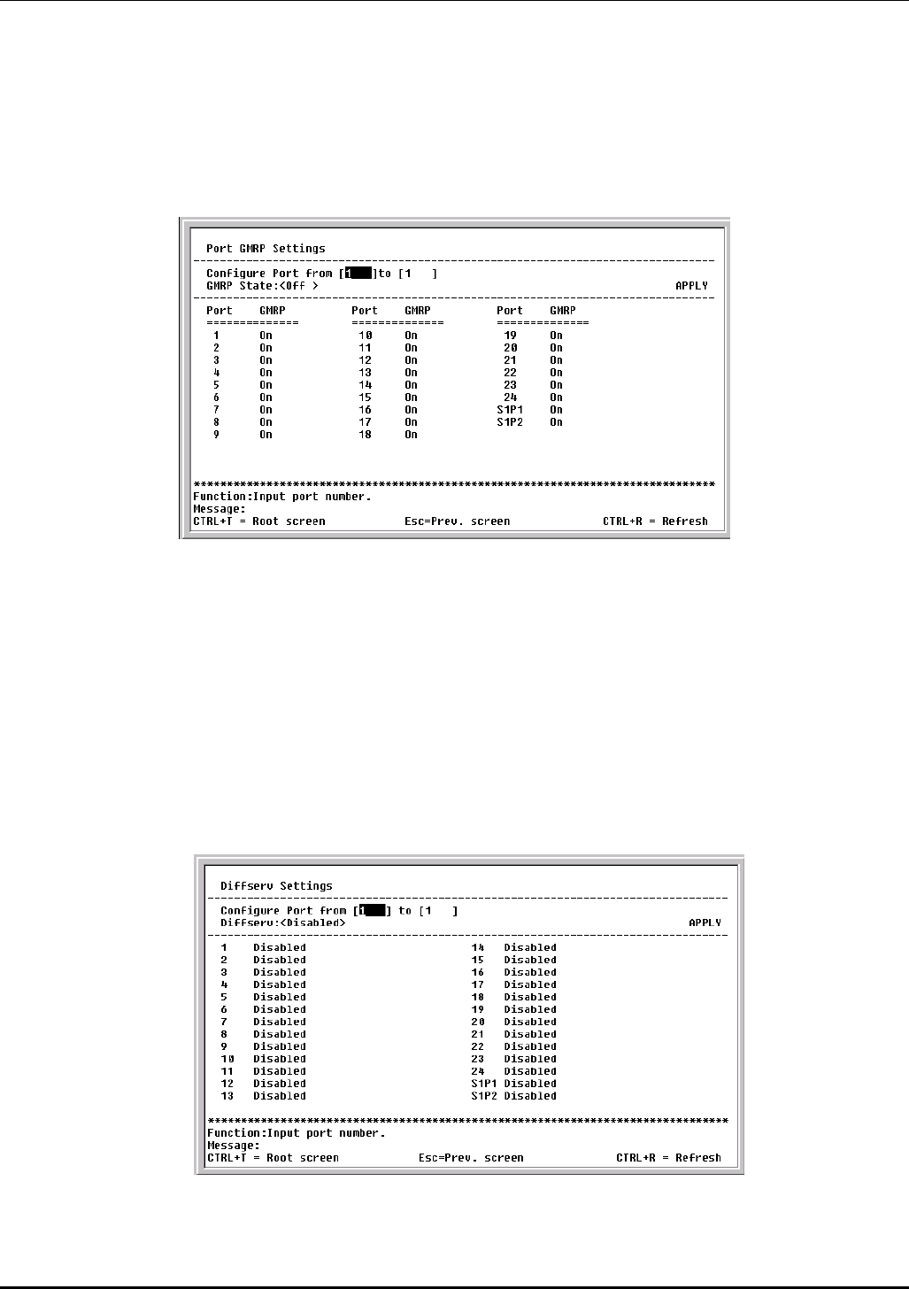
DES-3226 NWay Standalone Fast Ethernet Switch User’s Guide
This screen allows you to configure traffic class priority by specifying the class value, from 0 to 3, of the
Switch’s eight levels of priority. Press APPLY to let your changes take effect.
Configure Port GMRP Settings
Select Configure Port GMRP Settings and press Enter to access the following screen:
Figure 6-38. Port GMRP Settings screen
This screen allows you to enable Group Multicast Registration Protocol for individual ports by entering
the port or port range in the first field, toggling GMRP State to On in the second field, and pressing
APPLY to let your changes take effect.
Note: You must first enable GMRP globally on the Configure Advanced Switch Features screen
before it can be used on the port level.
Configure DIFFSERV Settings
Select Configure DIFFSERV Settings and press Enter to access the following screen:
Figure 6-39. Diffserv Settings screen
66
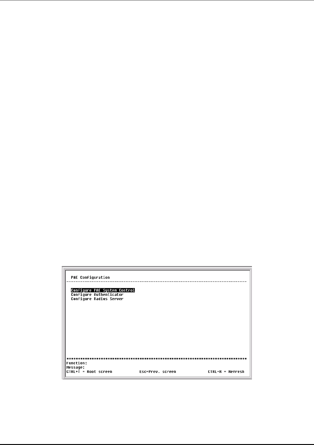
DES-3226 NWay Standalone Fast Ethernet Switch User’s Guide
Differentiated Services brings scalable Quality of Service to the Internet Protocol environment, using a
Type of Service (TOS) field in the IP header. The Switch has the capability to change the TOS
precedence field (the first 3 bits of the TOS field) based on the packet classification.
This screen allows you to set the following features:
• Configure Port from [ ] to [ ] – Enter the port or ports to be set.
• Diffserv – Choose from three options: Disabled, DSCP, and TOS.
• Mode – Under DSCP (Differentiated Service Code Point), there are two choices, Change if 0 or
Force Overwrite. If Force Overwrite is selected, the differentiated services field of an incoming
Ipv4 packet will be overwritten with the entered value. When Change if 0 is selected, the
differentiated services field of an incoming Ipv4 packet will be overwritten with the entered value
if the original value of the DSCP filed is zero. There are three choices under TOS (Type of
Service): TOS Overwrite 802.1p, 802.1p Overwrite TOS, and Force Overwrite. If Force Overwrite is
selected, the IP TOS precedence of incoming Ipv4 packets will be overwritten with the entered
value. If TOS Overwrite 802.1p is selected, the 802.1p tag control priority field of incoming Ipv4
packets will change to the value in the IP TOS precedence field. This action both alerts this field
in the packet and changes the 802.1p priority used to determine the hardware CoS queue. If
802.1p Overwrite TOS is selected, the IP TOS precedence of incoming Ipv4 packets will be
changed to the value in the 802.1p tag control priority field.
• DCSP value – Enter a DCSP value between 0 and 63 in this field.
• TOS value – Enter a TOS value between 0 and 7 in this field.
Configure Port Access Entity
The DES-3226 allows you to set the authentication status of individual ports on your Switch on the
following menu.
Select Configure Port Access Entity on the Configuration menu and press Enter.
Figure 6-40. PAE Configuration menu
PAE System Configuration
Select Configure PAE System Control and press Enter to access the following menu:
67
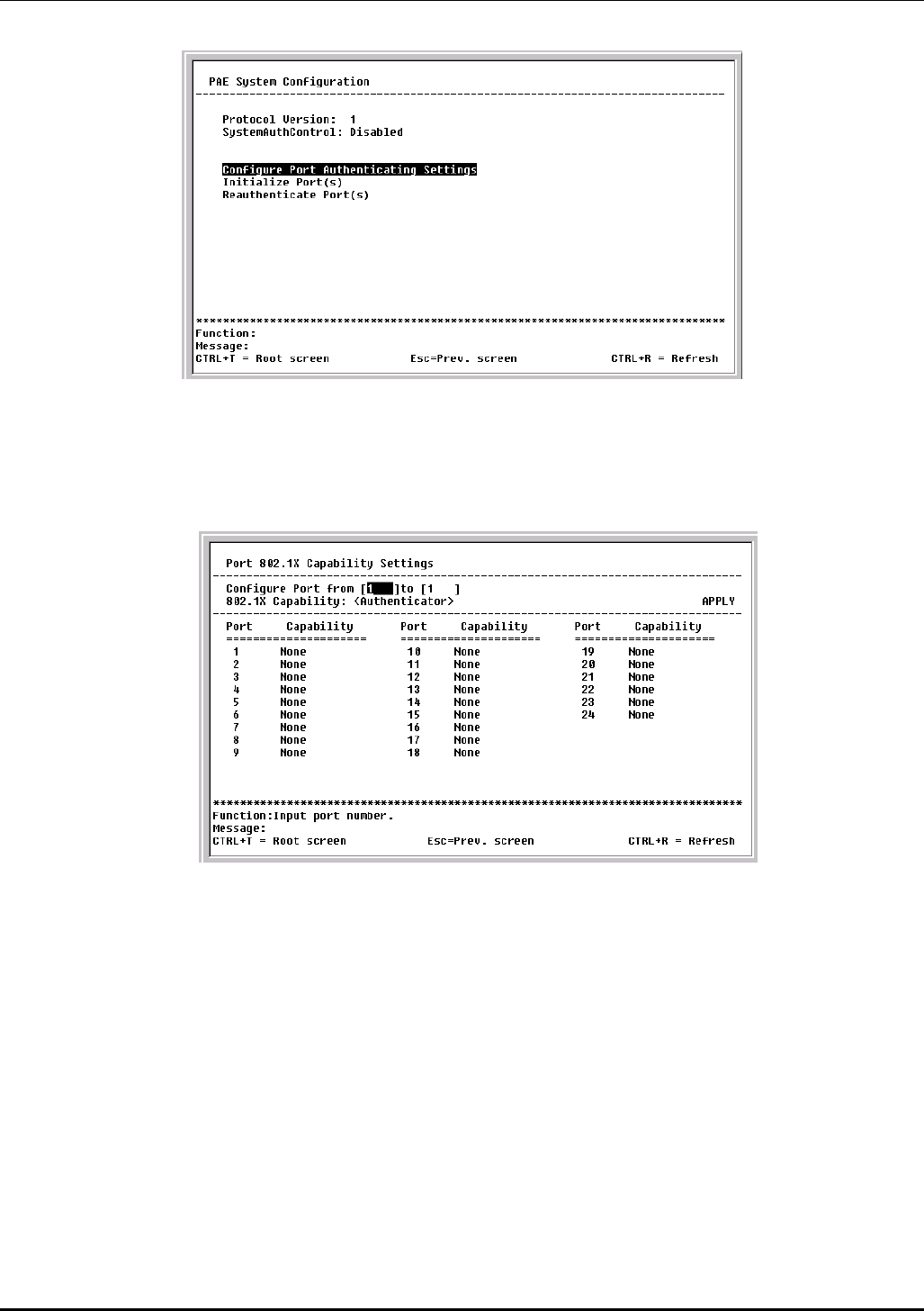
DES-3226 NWay Standalone Fast Ethernet Switch User’s Guide
Figure 6-41. PAE System Configuration menu
This menu displays the current Protocol Version being used and the status of the
SystemAuthControl. It also allows you to access the following three additional Port Access Entity
System Configuration screens.
Figure 6-42. Port 802.1X Capability Settings screen
To set up the Switch’s 802.1X port-based authentication, select which ports are to be configured in the
Configure Port from [ ] to [ ] field. Next, enable the selected ports by toggling the 802.1X Capability
field to Authenticator. Press APPLY to let your change take effect.
Note: You cannot configure a port to Authenticator when it is either a trunk port or LACP member port.
68

DES-3226 NWay Standalone Fast Ethernet Switch User’s Guide
Figure 6-43. Initialize Port(s) screen
This screen allows you to initialize a port or group of ports. The table also displays the current status of
the port(s) once you press START.
This screen displays the following information:
• Port – The port number.
• AuthState – The Authenticator PAE State will display one of the following: Initialize,
Disconnected, Connecting, Authenticating, Authenticated, Aborting, Held, ForceAuth, ForceUnauth,
and N/A.
• BackendState – The Backend Authentication State will display one of the following: Request,
Response, Success, Fail, Timeout, Idle, Initialize, and N/A.
• AdmDir – The Administrative Controlled Directions are both and in.
• OprDir – The Operational Controlled Directions are both and in.
• PortStatus – The status of the controlled port can be authorized, unauthorized, or N/A.
• PortControl – The controlled port can be forceUnauthorized, auto, or forceAuthorized.
69

DES-3226 NWay Standalone Fast Ethernet Switch User’s Guide
Figure 6-44. Reauthenticate Ports(s) menu
This screen allows you to reauthenticate a port or group of ports. The table also displays the current
status of the port(s) once you press START.
This screen displays the following information:
• Port – The port number.
• AuthState – The Authenticator PAE State will display one of the following: Initialize,
Disconnected, Connecting, Authenticating, Authenticated, Aborting, Held, ForceAuth, ForceUnauth,
and N/A.
• BackendState – The Backend Authentication State will display one of the following: Request,
Response, Success, Fail, Timeout, Idle, Initialize, and N/A.
• AdmDir – The Administrative Controlled Directions are both and in.
• OprDir – The Operational Controlled Directions are both and in.
• PortStatus – The status of the controlled port can be authorized, unauthorized, or N/A.
• PortControl – The controlled port can be forceUnauthorized, auto, or forceAuthorized.
Configure 802.1X – Authenticator Configuration
Select Configure Authenticator on the PAE Configuration menu and press Enter to access the
following screen:
70
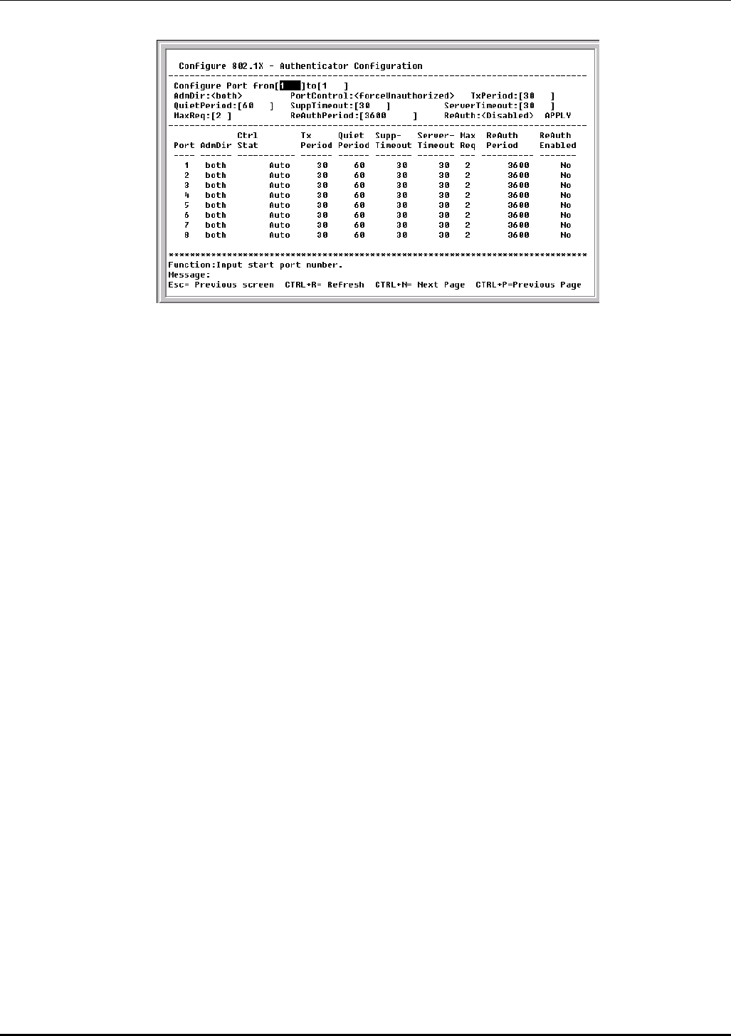
DES-3226 NWay Standalone Fast Ethernet Switch User’s Guide
Figure 6-45. Configure 802.1X – Authenticator Configuration screen
This screen allows you to set the following features:
• Configure Port from [ ] to [ ] – Enter the port or ports to be set.
• AdmDir:<both> – Sets the administrative-controlled direction to either in or both. If in is
selected, control is only exerted over incoming traffic through the port you selected in the first
field. If both is selected, control is exerted over both incoming and outgoing traffic through the
controlled port selected in the first field.
• PortControl:<auto> – This allows you to control the port authorization state. Select
forceAuthorized to disable 802.1X and cause the port to transition to the authorized state
without any authentication exchange required. This means the port transmits and receives
normal traffic without 802.1X-based authentication of the client. If forceUnauthorized is
selected, the port will remain in the unauthorized state, ignoring all attempts by the client to
authenticate. The switch cannot provide authentication services to the client through the
interface. The third option is auto. This enables 802.1X and causes the port to begin in the
unauthorized state, allowing only EAPOL frames to be sent and received through the port. The
authentication process begins when the link state of the port transitions from down to up, or
when an EAPOL-start frame is received. The switch then requests the identity of the client and
begins relaying authentication messages between the client and the authentication server.
• TxPeriod:[30 ] – This sets the TxPeriod of time for the authenticator PAE state machine. This
value determines the period of an EAP Request/Identity packet transmitted to the client.
• QuietPeriod:[60 ] – This allows you to set the number of seconds that the switch remains in the
quiet state following a failed authentication exchange with the client.
• SuppTimeout:[30 ] – This value determines timeout conditions in the exchanges between the
Authenticator and the client.
• ServerTimeout:[30 ] – This value determines timeout conditions in the exchanges between the
Authenticator and the authentication server.
• MaxReq:[2 ] – The maximum number of times that the switch will retransmit an EAP Request to
the client before it times out of the authentication sessions
• ReAuthPeriod:[3600 ] – A constant that defines a nonzero number of seconds between periodic
reauthentication of the client.
71
DES-3226 NWay Standalone Fast Ethernet Switch User’s Guide
• ReAuth:<Disabled> – Determines whether regular reauthentication will take place on this port.
Configure Radius Server
Select Configure Radius Server on the PAE Configuration menu and press Enter to access the
following screen:
Figure 6-46. Configure Radius Server menu
This menu offers three configuration choices for the radius server.
Figure 6-47. Configure General Radius Server Setting screen
This screen allows you to set the following features:
• AuthProtocol: <Radius Server(Support EAP)> – Toggle between the authentication protocol
options: Radius Server(Support EAP) and Local. In Local mode, use local authenticating (based
on local user settings) rather than a remote RADIUS server.
• Radius Dead Time:[1 ] –This specifies the number of minutes a RADIUS server which is not
responding to authentication requests is considered unavailable and is passed over by further
requests for RADIUS authentication.
72
DES-3226 NWay Standalone Fast Ethernet Switch User’s Guide
• Radius Time Out:[10 ] – This specifies the number of seconds NAS waits for a reply to a
RADIUS request before transmitting the request.
• Radius Maximum Retransmit:[2 ] –This specifies the number of times NAS transmits each
RADIUS request to the server before giving up.
• Accounting Method:<Radius Server> – To use a RADIUS Server, toggle from None to Radius
Server.
• Accounting Mode:<Start and Stop> – Select the desired method: Start and Stop, Stop only, or
None.
Figure 6-48. Configure Authentic Radius Server screen
This screen allows you to set the following features:
• Succession: <First> – Choose the desired RADIUS server to configure: First, Second or Third.
• Radius Server: [0.0.0.0] – Set the RADIUS server IP.
• Authentic Port:[ 1813 ] – Set the RADIUS authentic server(s) UDP port. The default value is
1813.
• Accounting Port:[ 1813 ] – Set the RADIUS account server(s) UDP port. The default value is
1813.
• Key – Set the key the same as that of the RADIUS server.
• Confirm Key – Confirm the shared key is the same as that of the RADIUS server.
• Status:<Invalid> –This allows you to set the RADIUS server as Valid or Invalid.
73
DES-3226 NWay Standalone Fast Ethernet Switch User’s Guide
Figure 6-49. Configure Local Users screen
The fields on this screen allow you to add or remove local users.
Network Monitoring
The DES-3226 provides extensive network monitoring capabilities.
To display the network data compiled by the Switch, highlight Network Monitoring on the main menu
and press Enter.
Figure 6-50. Network Monitoring Menu
Port Utilization
To view the port utilization of all the ports on the Switch, highlight Port Utilization on the Network
Monitoring Menu and press Enter:
74
DES-3226 NWay Standalone Fast Ethernet Switch User’s Guide
Figure 6-51. Port Utilization screen
The Port Utilization screen shows the number of packets transmitted and received per second and
calculates the percentage of the total available bandwidth being used on the port (displayed under
%Util.). Highlight CLEAR COUNTER and press Enter to reset the counters.
Port Error Packets
To view the error statistics for a port, highlight Port Error Packets on the Network Monitoring Menu
and press Enter:
Figure 6-52. Port Error Statistic screen
Enter the port number of the port to be viewed. The Interval field can be toggled from 2 seconds to 1
minute, or suspend. This sets the interval at which the error statistics are updated. Highlight CLEAR
COUNTER and press Enter to reset the counters.
Port Packet Analysis
To view an analysis of the size of packets received or transmitted by a port, highlight Port Packet
Analysis on the Network Monitoring Menu and press Enter:
75
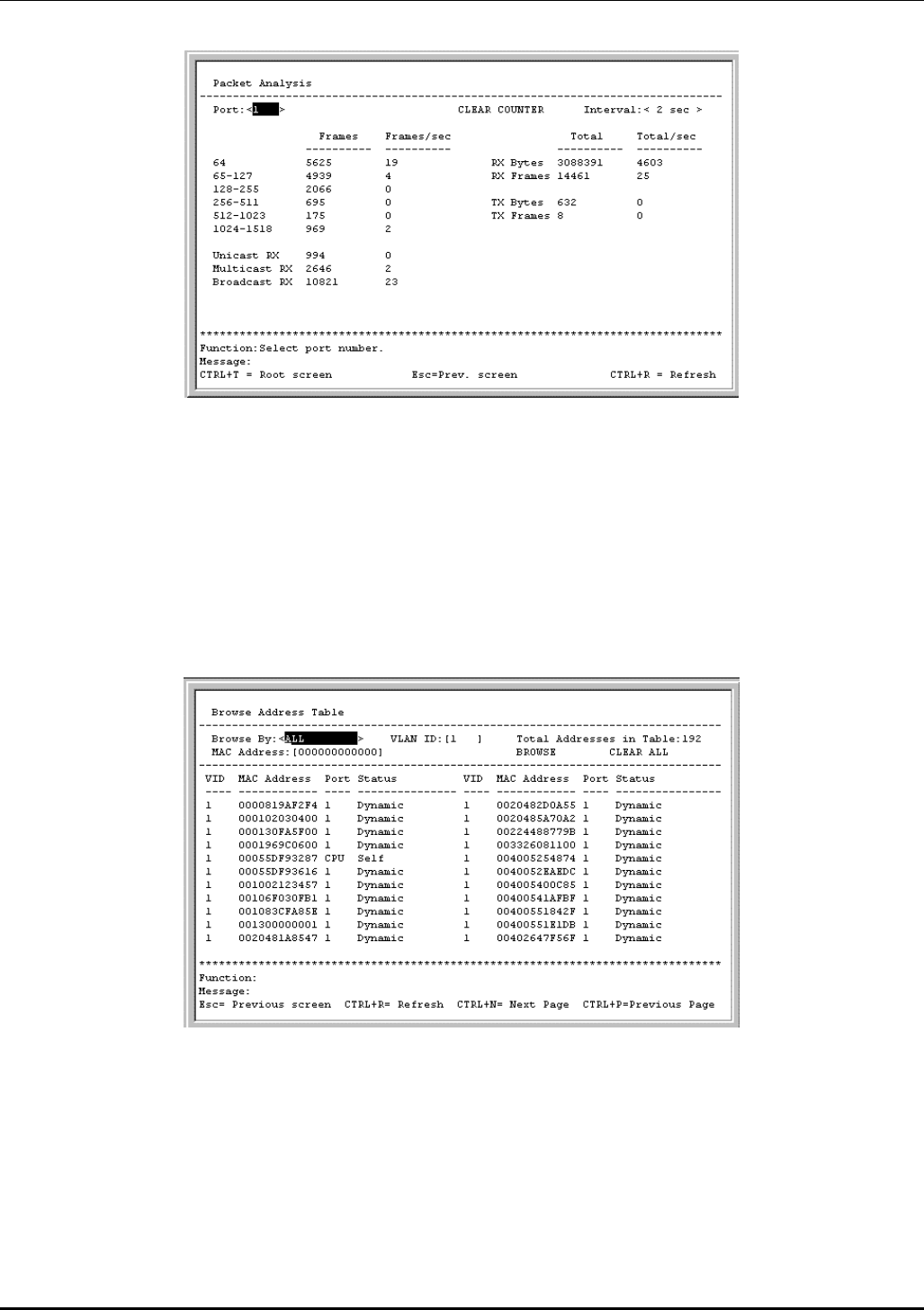
DES-3226 NWay Standalone Fast Ethernet Switch User’s Guide
Figure 6-53. Packet Analysis table
In addition to the size of packets received or transmitted by the selected port, statistics on the number
of unicast, multicast, and broadcast packets are displayed. Highlight CLEAR COUNTER and press
Enter to reset the counters.
Browse MAC Address
To view the MAC address forwarding table, highlight Browse MAC Address on the Network Monitoring
Menu and press Enter:
Figure 6-54. Browse Address Table screen
The Browse By field can be toggled between ALL, MAC Address, Port, and VLAN. This sets a filter to
determine which MAC addresses from the forwarding table are displayed. ALL specifies no filter.
To search for a particular MAC address:
Toggle the Browse By field to MAC Address. A MAC Address field will appear. Enter the MAC address
in the field and press Enter. Highlight BROWSE and press Enter to initiate the browsing action.
Highlight CLEAR ALL and press Enter to reset the table counters.
76
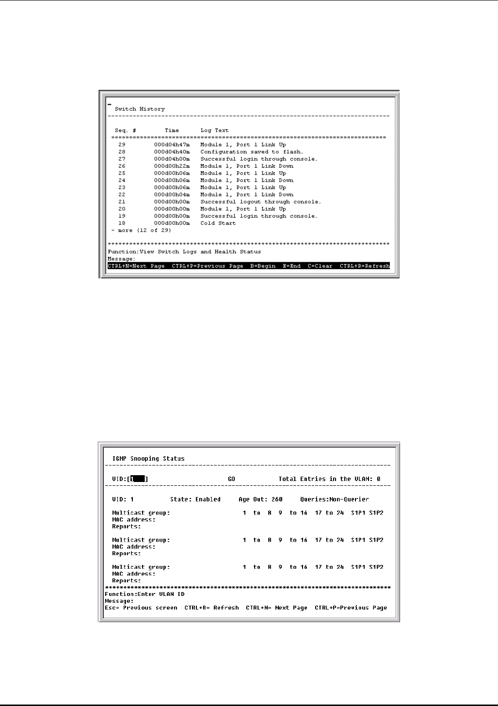
DES-3226 NWay Standalone Fast Ethernet Switch User’s Guide
Switch History
To view the switch history log, highlight Switch History from the Network Monitoring Menu and
press Enter:
Figure 6-55. Switch History screen
IGMP Snooping
This allows the Switch’s IGMP Snooping table to be viewed. IGMP Snooping allows the Switch to read
the Multicast Group IP address and the corresponding MAC address from IGMP packets that pass
through the Switch. The ports where the IGMP packets were snooped are displayed, signified with an M.
The number of IGMP reports that were snooped is also displayed in the Reports field.
To view the IGMP Snooping table, highlight IGMP Snooping on the Network Monitoring Menu and
press Enter.
Figure 6-56. IGMP Snooping Status screen
77
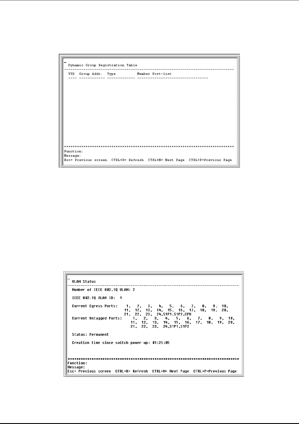
DES-3226 NWay Standalone Fast Ethernet Switch User’s Guide
Dynamic Group Registration Table
To view the Dynamic Group Registration Table, highlight Dynamic Group Registration Table on the
Network Monitoring Menu and press Enter.
Figure 6-57. Dynamic Group Registration Table screen
This read-only table contains filtering information for VLANs configured into the bridge by (local or
network) management, or learned dynamically, specifying the set of ports to which frames received on a
VLAN for this FDB and containing a specific Group destination address are allowed to be forwarded.
VLAN Status
This allows the status for each of the switch’s VLANs to be viewed.
To view the VLAN Status table, highlight VLAN Status on the Network Monitoring Menu and press
Enter.
Figure 6-58. VLAN Status screen
78
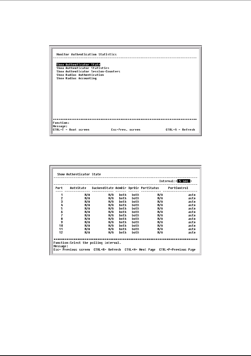
DES-3226 NWay Standalone Fast Ethernet Switch User’s Guide
Port Access Control Statistics
To view the Monitor Authentication Statistics menu, highlight Port Access Control Statistics on
the Network Monitoring Menu and press Enter.
Figure 6-59. Monitor Authentication Statistics screen
Select the item from the screen above to show the desired information.
Figure 6-60. Show Authenticator State screen
This read-only field displays Authenticator State information. The polling interval can be set between 2
seconds and 1 minute using the space bar.
The information on this screen is described as follows:
• AuthState – The Authenticator PAE state value can be: Initialize, Disconnected, Connecting,
Authenticating, Authenticated, Aborting, Held, Force_Auth, Force_Unauth, or N/A. N/A (Not Available)
indicates that the port’s authenticator capability is disabled.
• BackendState – The Backend Authentication state can be Request, Response, Success, Fail,
Timeout, Idle, Initialize, or N/A. N/A indicates that the port’s authenticator capability is disabled.
• AdmDir – Admin Controlled Directions can be either both or in.
79
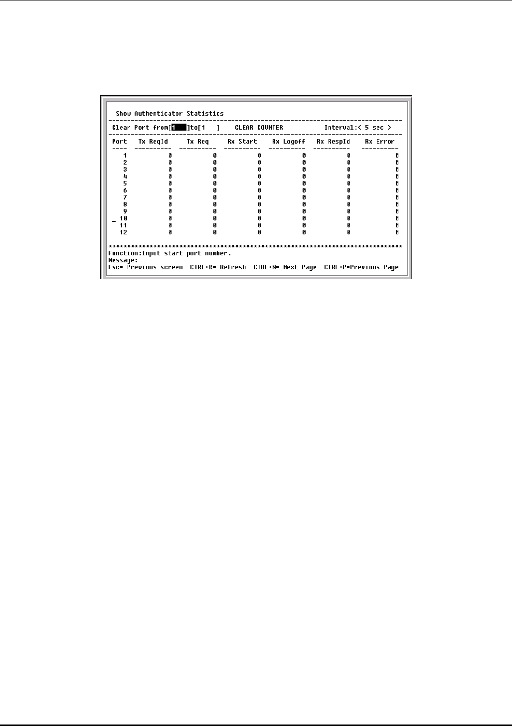
DES-3226 NWay Standalone Fast Ethernet Switch User’s Guide
• OprDir – Oper Controlled Directions can be either both or in.
• PortStatus – Auth Controlled Port Status can be Authorized, Unauthorized, or N/A.
• Port Control – Auth Controlled Port Control can be ForceAuthorized, ForceUnauthorized, or Auto.
Figure 6-61. Show Authenticator Statistics screen
This read-only field displays Authenticator Statistics.
To reset the statistics counters on this screen, enter the desired ports in the Clear Port from [ ] to [ ]
field and then press CLEAR COUNTER. The polling interval can be set between 2 seconds and 1 minute
using the space bar.
The information on this screen is described as follows:
• Tx ReqId – The number of EAP Req/Id frames that have been transmitted by this Authenticator.
• Tx Req – The number of EAP Request frames (other than Rq/Id frames) that have been transmitted
by this Authenticator.
• Rx Start – The number of EAPOL Start frames that have been received by this Authenticator.
• Rx Logoff – The number of EAPOL Logoff frames that have been received by this Authenticator.
• Rx RespId – The number of EAP Resp/Id frames that have been received by this Authenticator.
• Rx Error – The number of EAPOL frames that have been received by this Authenticator in which
the frame type is not recognized.
80
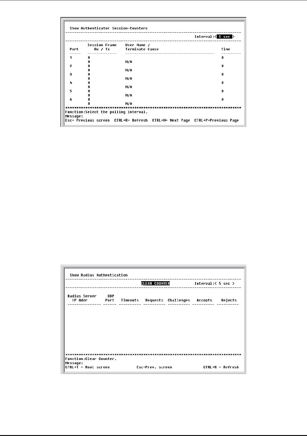
DES-3226 NWay Standalone Fast Ethernet Switch User’s Guide
Figure 6-62. Show Authenticator Session-Counters screen
This read-only field displays Authenticator Session-Counters information. The polling interval can be
set between 2 seconds and 1 minute using the space bar.
The information on this screen is described as follows:
• Session Frame Rx – The number of user data frames received on this Port during the session.
• Session Frame Tx – The number of user data frames transmitted on this Port during the session.
• User Name – The User Name representing the identity of the client PAE.
• Terminate Cause – The reason for the session termination. This parameter can take the following
values: Client Logoff, Port Failure, Client Restart, Reauthentication Failure, AuthControlledPortControl
set to ForceUnauthorized, Port Re-initialization, Port Administratively Disabled, and Not Terminated Yet.
• Time – The session time is the duration of time in seconds.
Figure 6-63. Show Radius Authentication screen
This read-only field displays RADIUS Authentication information. To reset the statistics counters on
this screen, press CLEAR COUNTER. The polling interval can be set between 2 seconds and 1 minute
using the space bar.
81
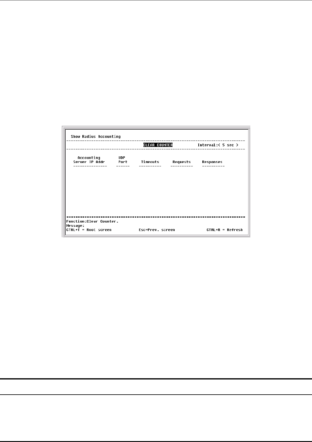
DES-3226 NWay Standalone Fast Ethernet Switch User’s Guide
The information on this screen is described as follows:
• Radius Server IP Addr – The remote RADIUS server IP address.
• UDP Port – The UDP socket port numbers of the RADIUS server.
• Timeouts – The counter of timeouts from RADIUS authentication.
• Requests – The counter of access requests from RADIUS authentication.
• Challenges – The counter of access challenges from RADIUS authentication.
• Accepts – The counter for the number of acceptances from RADIUS authentication.
• Rejects – The counter for the number of rejections from RADIUS authentication.
Figure 6-64. Show Radius Accounting screen
This read-only field displays RADIUS Accounting information. To reset the statistics counters on this
screen, press CLEAR COUNTER. The polling interval can be set between 2 seconds and 1 minute using
the space bar.
The information on this screen is described as follows:
• Accounting Server IP Addr – The IP address of the RADIUS accounting server.
• UDP Port – The UDP socket port number of the RADIUS accounting server.
• Timeouts – The counter of the timeout connections to the RADIUS accounting server.
• Requests – The counter of the requests from the RADIUS accounting server.
• Responses – The counter for the number of rejections from RADIUS accounting server.
SNMP Manager Configuration
The Switch sends out SNMP traps to network management stations whenever certain exceptional events
occur, such as when the Switch is turned on or when a system reset occurs. The Switch allows traps to
be routed to up to four different network management hosts.
82

DES-3226 NWay Standalone Fast Ethernet Switch User’s Guide
For a detailed list of Trap Types used for this Switch, see the Traps section of Chapter 5, “Switch
Management and Operating Concepts.”
SNMP (V1/V2C) implements a rudimentary form of security by requiring that each request include a
community name. A community name is an arbitrary string of characters used as a “password” to
control access to the Switch. If the Switch receives a request with a community name it does not
recognize, it will trigger an authentication trap.
The SNMP allows up to four different community names to be defined. The community name public is
defined by default; you can change this name in addition to adding others. You will need to coordinate
these names with the community name settings you use in your network management system.
Choose SNMP Manager Configuration to access the third item on the main menu. The following screen
appears:
Figure 6-65. SNMP Manager Configuration screen
The following SNMP Manager and Trap Manager Configuration parameters can be set:
• SNMP Community String – The community string that will be included on SNMP packets sent
to and from the switch. Any station not privy to this community will not receive the packet.
• Access Right – Allows each community to be separately set to either Read Only, meaning that
the community member can only view switch settings or Read/Write, which allows the member
to change settings in the switch.
• Status – Determines whether this community name entry is Valid or Invalid. An entry can be
disabled by changing its status to Invalid.
• IP Address – The IP address of the network management station to receive traps.
The Security IP section allows you to create a list of IP addresses that are allowed to access the Switch
via SNMP or Telnet.
Highlight APPLY and press Enter to allow your changes to take effect.
83
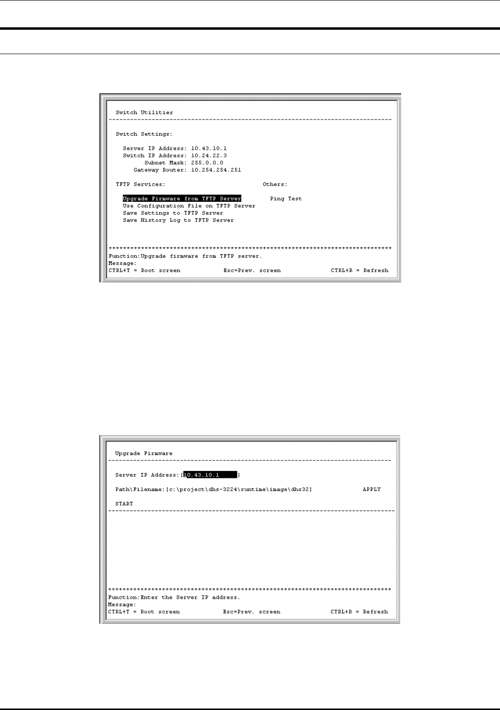
DES-3226 NWay Standalone Fast Ethernet Switch User’s Guide
System Utilities
To access the Switch Utilities menu, highlight System Utilities on the main menu and press Enter.
Figure 6-66. Switch Utilities menu
Note: Trivial File Transfer Protocol (TFTP) services allow the switch firmware to be upgraded by
transferring a new firmware file from a TFTP server to the Switch. A configuration file can
also be loaded into the Switch from a TFTP server, switch settings can be saved to the TFTP
server, and a history log can be uploaded from the Switch to the TFTP server.
Upgrade Firmware from TFTP Server
To update the Switch’s firmware, highlight Upgrade Firmware from TFTP Server and press Enter.
Figure 6-67. Upgrade Firmware screen
Enter the IP address of the TFTP server in the Server IP Address field.
Note: The TFTP server must be on the same IP subnet as the Switch.
84
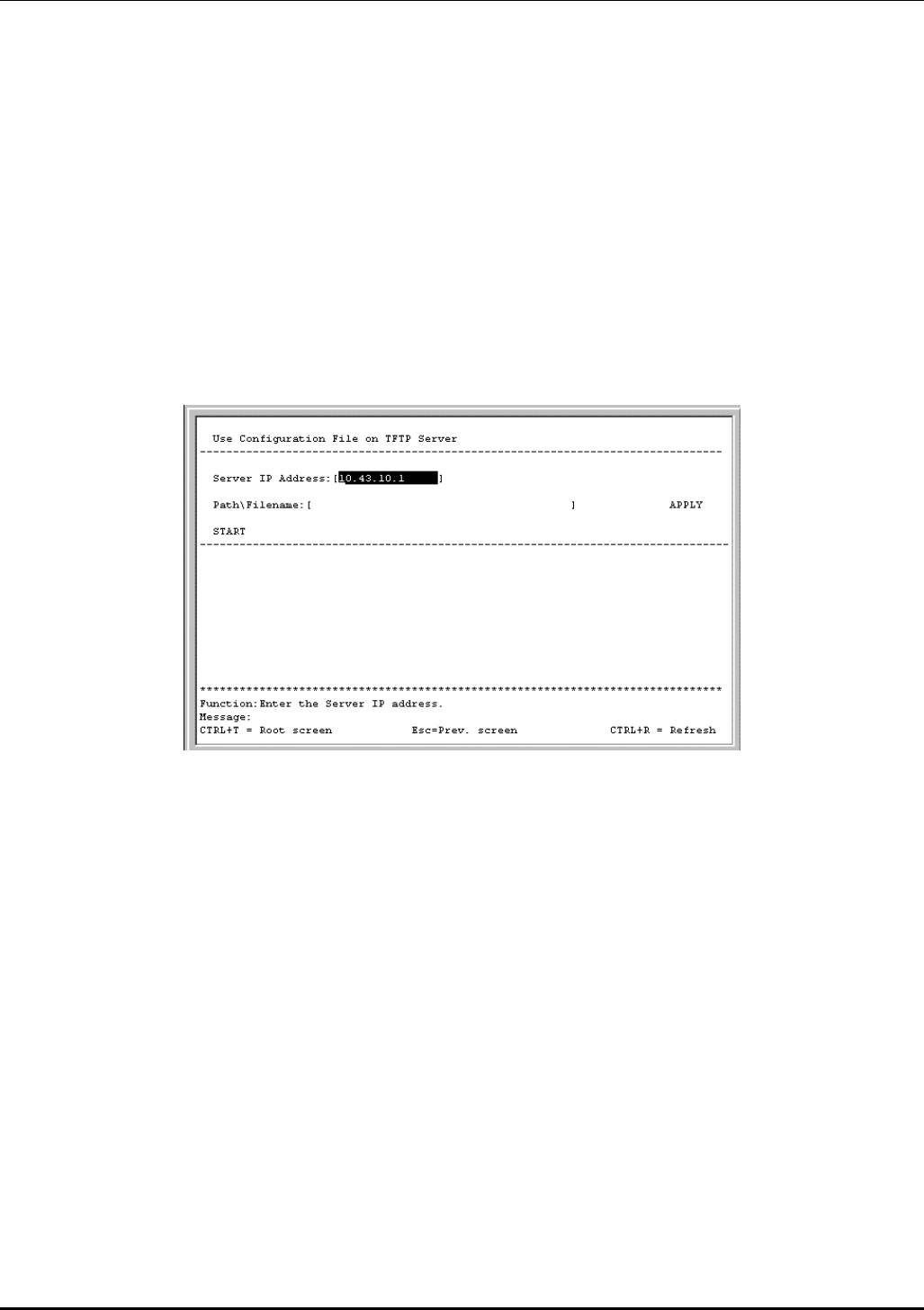
DES-3226 NWay Standalone Fast Ethernet Switch User’s Guide
Enter the path and the filename to the firmware file on the TFTP server.
Note: The TFTP server must be running TFTP server software to perform the file transfer. TFTP
server software is a part of many network management software packages, or can be
obtained as a separate program.
Highlight APPLY and press Enter to record the IP address of the TFTP server. Use Save Changes from
the main menu to enter the address into NV-RAM
Highlight START and press Enter to initiate the file transfer.
Use Configuration File on TFTP Server
To download a switch configuration file from a TFTP server, highlight Use a Configuration File on
TFTP Server and press Enter.
Figure 6-68. Use Configuration File on TFTP Server screen
Enter the IP address of the TFTP server and specify the location of the switch configuration file on the
TFTP server.
Highlight APPLY and press Enter to record the IP address of the TFTP server. Use Save Changes from
the main menu to enter the address into NV-RAM
Highlight START and press Enter to initiate the file transfer.
Note: Configuration files used in the earlier version of this switch (firmware version 1.0) are not
supported by the present version (firmware version 2.0). The Switch Information screen displays
the firmware version.
Save Settings to TFTP Server
To upload a settings file to the TFTP server, highlight Save Settings to TFTP Server and press Enter.
85
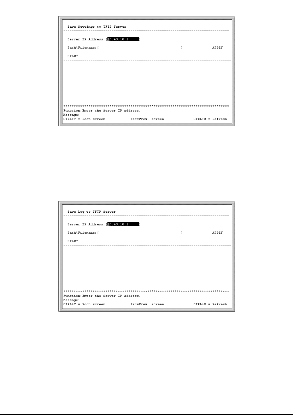
DES-3226 NWay Standalone Fast Ethernet Switch User’s Guide
Figure 6-69. Save Settings to TFTP Server screen
Enter the IP address of the TFTP server and the path and filename of the settings file on the TFTP
server and press APPLY. Highlight START and press Enter to initiate the file transfer.
Save History Log to TFTP Server
To save a History Log on a TFTP server, highlight Save History Log to TFTP Server and press Enter.
Figure 6-70. Save Log to TFTP Server screen
Enter the IP address of the TFTP server and the path and filename for the history log on the TFTP
server. Highlight APPLY and press Enter to make the changes current. Highlight START and press
Enter to initiate the file transfer.
Ping Test
To test the connection with another network device using Ping, highlight Ping Test and press Enter.
86
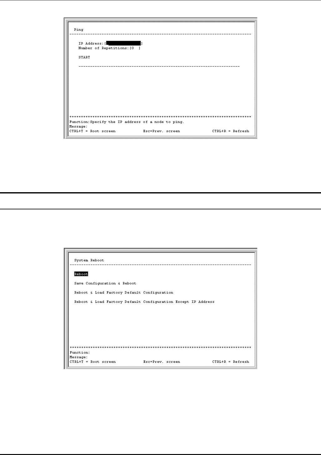
DES-3226 NWay Standalone Fast Ethernet Switch User’s Guide
Figure 6-71. Ping screen
Enter the IP address of the network device to be Pinged and the number of test packets to be sent (3 is
usually enough). Highlight START and press Enter to initiate the Ping program.
Reboot
The DES-3226 has several reboot options.
To reboot the Switch from the console, highlight Reboot from the main menu and press Enter.
Figure 6-72. System Reboot menu
The reboot options are as follows:
• Reboot – Simply restarts the Switch. Any configuration settings not saved using Save Changes
from the main menu will be lost. The Switch’s configuration will be restored to the last configuration
saved in NV-RAM.
87
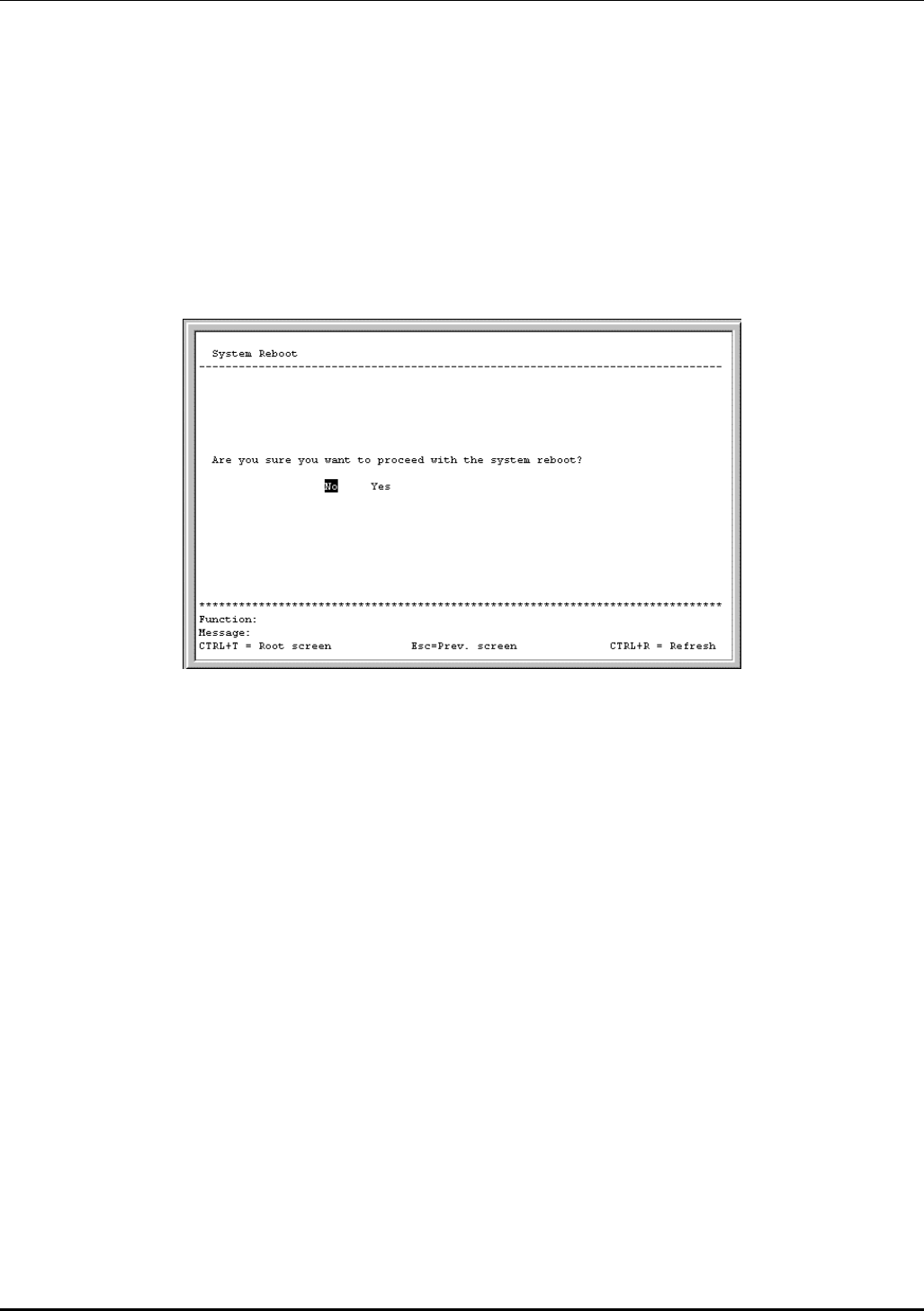
DES-3226 NWay Standalone Fast Ethernet Switch User’s Guide
• Save Configuration & Reboot – Saves the configuration to NV-RAM (identical to using Save
Changes) and then restarts the Switch.
• Reboot & Load Factory Default Configuration – Restarts the Switch using the default factory
configuration. All configuration data will be lost. This is identical to using Factory Reset and then
Reboot.
• Reboot & Load Factory Default Configuration Except IP Address – Restarts the Switch using the
default factory configuration, except the user configured IP address will be retained. All other
configuration data will be lost.
A confirmation screen will appear:
Figure 6-73. System Reboot confirmation screen
To reboot the Switch, in the mode entered above, highlight Yes and press Enter.
88

DES-3226 NWay Standalone Fast Ethernet Switch User’s Guide
7
WEB-BASED NETWORK MANAGEMENT
Introduction
The DES-3226 offers an embedded Web-based (HTML) interface allowing users to manage the Switch
from anywhere on the network through a standard browser, such as Opera, Netscape
Navigator/Communicator, or Microsoft Internet Explorer. The Web browser acts as a universal access
tool and can communicate directly with the Switch using the HTTP protocol. Your browser window may
vary with the screen shots (pictures) in this guide.
The Web-based management module and the Console program (and Telnet) are different ways to access
the same internal switching software and configure it. Thus, all settings encountered in Web-based
management are the same as those found in the console program.
Note: This Web-based Management Module does not accept Chinese language input (or other
languages requiring 2 bytes per character).
Getting Started
The first step in getting started in using Web-based management for your Switch is to secure a browser.
A Web browser is a program that allows a person to read hypertext, for example, Opera, Netscape
Navigator, or Microsoft Internet Explorer. Follow the installation instructions for the browser.
The second and last step is to configure the IP interface of the Switch. This should be done manually
through a console (see the Configure IP Address section in the “Using The Console Interface” chapter).
You are now ready to begin managing your Switch by simply running the browser installed on your
computer and pointing it to the IP address you have defined for the device. The URL in the address bar
should read something like: http://123.123.123.123, where the numbers 123 represent the IP address
of the switch. Please note that the proxy for session connection should be turned off.
The following dialog box will open:
89
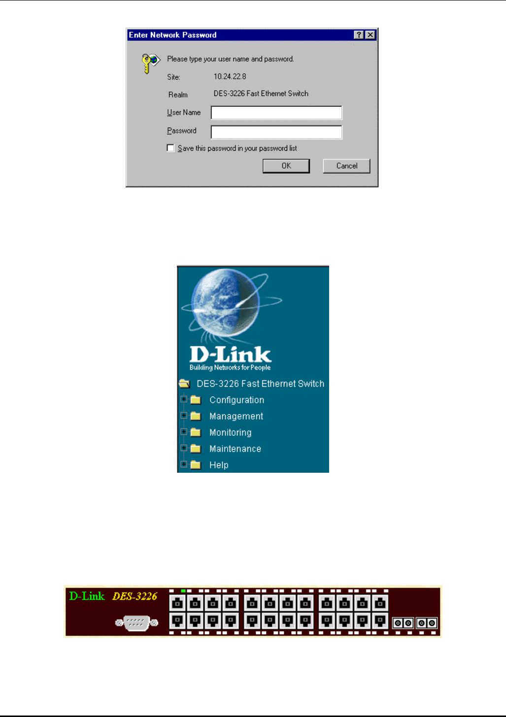
DES-3226 NWay Standalone Fast Ethernet Switch User’s Guide
Click OK as there is no preset user name or password on the Switch. This opens the main page in the
management module.
The panel on the left-hand side contains the main menu. The featured items include: Configuration,
Management, Monitoring, Maintenance, and Help.
These are the major categories for Switch management. Clicking on the small square hyperlink to the
left of the folder icons will cause a list of additional sub-menus to appear directly below each of the first
four main menu categories.
The top panel on the right-hand side contains a real-time front panel display of the Switch. Double-
clicking on a port will open the Rx Packets Analysis window. This can also be accessed through
Monitoring → Packets → Received(RX). Please see the Monitoring section in this chapter for a
detailed description.
The switch management features available in the Web-based are explained below.
90
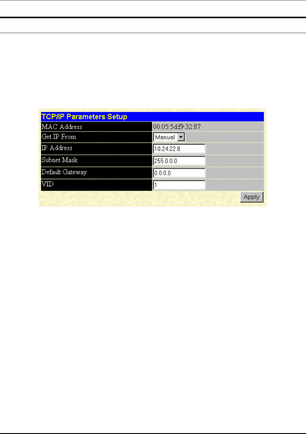
DES-3226 NWay Standalone Fast Ethernet Switch User’s Guide
Configuration
The first category includes: IP Address, Switch Information, Advanced Settings, Port Configuration,
Port Mirroring, Port LACP Trunking, IGMP Snooping, Port GMRP, Diffserv Settings, Spanning
Tree, Static Filtering Table, VLANs, Port Bandwidth, Threshold of Broadcast, Port Priority, Class
of Traffic, Class of Service, Port Security, PAE System Control, and Radius Server, as well
secondary screens.
IP Address
Figure 7-1. TCP/IP Parameters Setup window
This window is used to determine whether the Switch should get its IP Address settings from the user
(Manual), a BOOTP server, or a DHCP server. If you are not using either BOOTP or DHCP, enter the IP
Address, Subnet Mask, and Default Gateway of the Switch. If you enable BOOTP, you do not need to
configure any IP parameters because a BOOTP server automatically assigns IP configuration
parameters to the Switch. If you enable DHCP, a Dynamic Host Configuration Protocol request will be
sent when the Switch is powered up. Once you have selected a setting under Get IP From, click Apply
to activate the new settings.
The information is described as follows:
• MAC Address – The Ethernet address for the device. Also known as the physical address
• Get IP From – There are three choices for how the Switch receives its IP Address settings:
Manual, BOOTP, and DHCP.
• IP Address – The host address for the device on the TCP/IP network.
• Subnet Mask – The address mask that controls subnetting on your TCP/IP network.
• Default Gateway – The IP address of the device—usually a router—that handles connections to
other subnets and/or other TCP/IP networks.
• VID – The VLAN ID number.
91
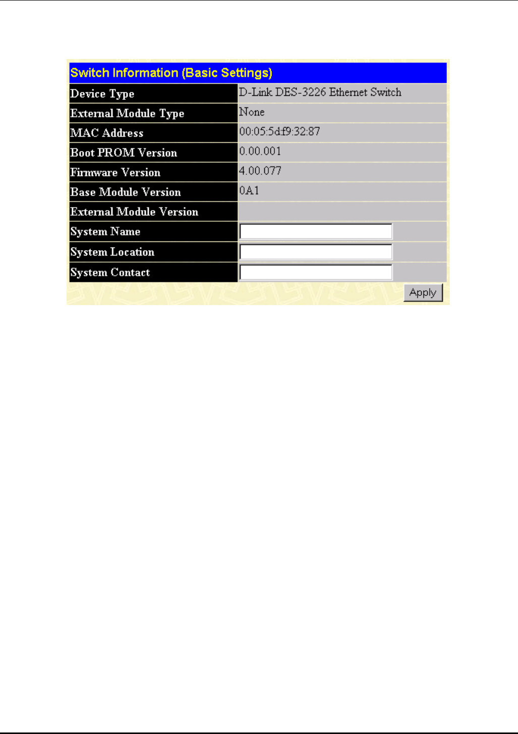
DES-3226 NWay Standalone Fast Ethernet Switch User’s Guide
Switch Information
Figure 7-2. Switch Information (Basic Settings) window
To set basic switch settings, enter a System Name in the first field, the physical location of the Switch
in the System Location field, and the name of the contact person responsible for the Switch in the
System Contact field. Then click Apply.
The information is described as follows:
• Device Type – A description of the Switch type.
• External Module Type – Description of optional module plugged into front slot.
• MAC Address – The Ethernet address for the device.
• Boot PROM Version – Version number for the firmware chip. This information is needed for
new runtime software downloads.
• Firmware Version – Version number of the firmware installed on the Switch. This can be
updated by using the Update Firmware window in the Reset and Update section.
• Base Module Version – Version number of the base module.
• External Module Version – Version of optional module plugged into front slot.
• System Name – A user-assigned name for the Switch.
• System Location – A user-assigned description for the physical location of the Switch.
• System Contact – Name of the person to contact should there be any problems or questions
with the system. You may also want to include a phone number or extension.
92
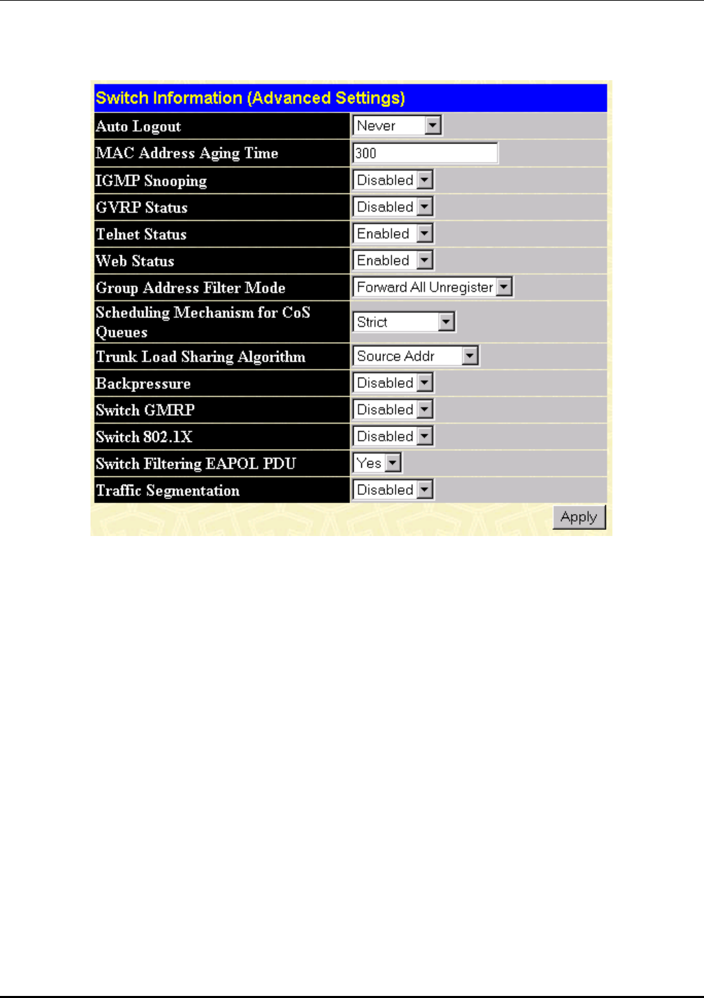
DES-3226 NWay Standalone Fast Ethernet Switch User’s Guide
Advanced Settings
Figure 7-3. Switch Information (Advanced Settings) window
After making the desired advanced setting Layer 2 changes, click Apply to let them take effect.
The information in the window is described as follows:
• Auto-Logout [2 Minutes]– This sets the time the interface can be idle before the Switch
automatically logs-out the user. The options are 2 minutes, 5 minutes, 10 minutes, 15 minutes, or
Never.
• MAC Address Aging Time [300 ] – This field specifies the length of time a learned MAC Address will
remain in the forwarding table without being accessed (that is, how long a learned MAC Address is
allowed to remain idle). The Aging Time can be set to any value between 10 and 1,000,000 seconds.
Note: A very long Aging Time can result with the out-of-date Dynamic Entries that may cause
incorrect packet filtering/forwarding decisions. A very short aging time may cause entries to
be aged out to soon, resulting in a high percentage of received packets whose source
addresses cannot be found in the address table, in which case the Switch will broadcast the
packet to all ports, negating many of the benefits of having a Switch.
• IGMP Snooping [Disabled] – This setting enables Internet Group Management Protocol (IGMP)
Snooping, which enables the Switch to read IGMP packets being forwarded through the Switch in
order to obtain forwarding information from them (learn which ports contain Multicast members.
• GVRP Status [Enabled] – Group VLAN Registration Protocol is a protocol that allows members to
dynamically join VLANs. This is used to enable or disable GVRP on the Switch
93

DES-3226 NWay Standalone Fast Ethernet Switch User’s Guide
• Telnet Status [Enabled] – Toggle to Enabled to allow access to the Switch over the network using
the TCP/IP Telnet protocol.
• Web Status [Enabled] – You can also use a Web-based browser to manage the Switch by toggling to
Enabled.
• Group Address Filter Mode [Forward All Unregister] – The IGMP filter mode for processing
multicast packets. The options are Forward All, Forward All Unregister, and Filtered All Unregister.
• Scheduling Mechanism for CoS Queues [Strict] – There are two Class of Service queue options,
RoundRobin and Strict. If Strict is selected, when the highest priority queue is full, those packets will
be the first to be forwarded. If RoundRobin is selected, the forwarding is based on the settings made
on the Class of Service Configuration screen.
• Trunk Load Sharing Algorithm [Source Addr] – The trunk load sharing options are Dst Address,
Src&Dst Address, and Src Address.
• Backpressure [Disabled] – This allows you to enable or disable the backpressure function for the
Switch.
• Switch GMRP [Disabled] – This allows you to set Group Multicast Registration Protocol (GMRP) for
the whole Switch.
• Switch 802.1X [Disabled] – This allows you to set 802.1X for the whole Switch.
• Switch Filtering EAPOL PDU [Yes] – This option is only available if 802.1X is disabled. When
enabled, this feature
• Traffic Segmentation [Disabled] – When this feature is Enabled, ports on the Switch are not able to
communicate with one another. If there is not an optional module present, Port 1 becomes the
server port. If there is a 1-port optional module, this port will be the server port. If there is a 2-port
optional module, both ports act as server ports.
94
DES-3226 NWay Standalone Fast Ethernet Switch User’s Guide
Port Configuration
Figure 7-4. Port Configuration window
Select the port you want to configure by using the drop-down menus in the From and To fields or click
on the port in the Switch front panel display at the top of the window. Follow these steps:
1. Enable or disable the port. If you choose Disabled in the State field, devices connected to that
port cannot use the Switch, and the Switch purges their addresses from its address table after
the MAC address aging time elapses.
95
DES-3226 NWay Standalone Fast Ethernet Switch User’s Guide
2. Configure the Speed/Duplex setting for the port. Select Auto to allow the port to select the best
transmission speed, duplex mode and flow control settings based on the capabilities of the
device at the other end. The other selections allow you to force the port to operate in the
specified manner. Select 100M/FULL for port operation at 100 Mbps and full duplex. Select
100M/HALF for port operation at 100 Mbps and half duplex. Select 10M/FULL for port
operation at 10 Mbps and full duplex. Select 10M/HALF for port operation at 10 Mbps and half
duplex.
3. Click Apply to let your changes take effect.
Port Mirroring
Figure 7-5. Port Mirroring window
The Switch allows you to copy frames transmitted and received on a port and redirect the copies to
another port. You can attach a monitoring device to the mirrored port, such as a sniffer or an RMON
probe, to view details about the packets passing through the first port.
To configure a mirror port, first select the Source Port from where you want to copy frames and the
Target Port, which receives the copies from the source port. This is the port where you will connect a
monitoring/troubleshooting device such as a sniffer or an RMON probe. Next, select the Source
Direction, Ingress, Egress, or Both, and change the Status pull-down menu to Enabled. Finally, click
Apply to let the changes take effect.
Note: You should not mirror a faster port or higher traffic ports to a slower port. For example, if
you try to mirror the traffic from a 100 Mbps port onto a 10 Mbps port, this can cause
throughput problems. The port you are copying frames from should always support an
equal or lower speed than the port to which you are sending the copies. Also, the target
port for the mirroring cannot be a member of a trunk group. Please note a target port and a
source port cannot be the same port.
96
DES-3226 NWay Standalone Fast Ethernet Switch User’s Guide
Port LACP Trunking
Figure 7-6. Port LACP Trunking Settings window
Port trunking allows several ports to be grouped together and to act as a single link. This gives a
bandwidth that is a multiple of a single link’s bandwidth.
Port trunking is most commonly used to link a bandwidth intensive network device or devices – such as
a server – to the backbone of a network.
The Switch allows the creation of up to 6 port trunking groups, each group consisting of up to 8 links
(ports). The trunked ports can be non-continuous (that is, have non-sequential port numbers). All of
the ports in the group must be members of the same VLAN. Further, the trunked ports must all be of
the same speed and should be configured as full duplex.
The configuration of the lowest numbered port in the group becomes the configuration for all of the
ports in the port trunking group. This port is called the Master Port of the group, and all configuration
options – including the VLAN configuration – that can be applied to the Master Port are applied to the
entire port trunking group.
Load balancing is automatically applied to the ports in the trunked group, and a link failure within the
group causes the network traffic to be directed to the remaining links in the group.
97
DES-3226 NWay Standalone Fast Ethernet Switch User’s Guide
The Spanning Tree Protocol will treat a port trunking group as a single link, on the switch level. On the
port level, the STP will use the port parameters of the Master Port in the calculation of port cost and in
determining the state of the port trunking group. If two redundant port trunking groups are configured
on the Switch, STP will block one entire group – in the same way STP will block a single port that has a
redundant link.
The Link Aggregate Control Protocol (LACP) allows you to bundle several physical ports together to form
one logical port. In contrast to traditional port trunking as explained above, LACP trunking requires
every member port to use the same protocol. If, for example, one member port on a switch does not
support LACP, then that port cannot be a member of the port trunking group.
The user-changeable parameters in the Switch are as follows:
• Group ID [1] – This field is for a group ID number for the port trunking group.
• Group Name [ ] – Enter a name for the port trunking group.
• Type [TRUNK] – If LACP is selected, each member of the port trunking group must support the Link
Aggregate Control Protocol. There is no protocol requirement if TRUNK is selected.
• State [Disabled] – This field can be toggled between Enabled and Disabled. This is used to turn a
port trunking group on or off. This is useful for diagnostics, to quickly isolate a bandwidth intensive
network device or to have an absolute backup aggregation group that is not under automatic
control.
• Member ports – Check each port of the port trunking group.
IGMP Snooping
Figure 7-7. IGMP Snooping Settings window
Internet Group Management Protocol (IGMP) snooping allows the Switch to recognize IGMP queries and
reports sent between network stations or devices and an IGMP host. When enabled for IGMP snooping,
the Switch can open or close a port to a specific device based on IGMP messages passing through the
Switch.
To set up IGMP snooping, enter a VLAN ID number in the first field and change the State field to
Enabled. Next, select the desired setting in the Querier State field—this determines the version of
IGMP that is used in your network—and enter values in the following three fields. A value between 1
and 255 can be entered for the Robustness Variable (default is 2). The Query Interval can be set
between 1 and 65535 seconds. This sets the time between IGMP queries. The Max Response allows a
setting between 1 and 25 seconds and specifies the maximum amount of time allowed before sending a
response report. Click Apply to make the settings effective.
98

DES-3226 NWay Standalone Fast Ethernet Switch User’s Guide
The user-changeable parameters in the Switch are as follows:
• VLAN ID [ 1] – Enter a VLAN ID number in this field.
• State [Enabled] – Use the drop-down menu to enable or disable IGMP settings.
• Querier State [Non-Querier] – Select from Non-Querier, V1-Querier, and V2-Querier. This is used to
specify the IGMP version (1 or 2) that will be used by the IGMP interface when making queries.
• Robustness Variable [ 2] – A tuning variable to allow for sub-networks that are expected to lose a
large number of packets. A value between 1 and 255 can be entered, with larger values being
specified for sub-networks that are expected to lose larger numbers of packets.
• Query Interval [ 125] – Allows the entry of a value between 1 and 65535 seconds, with a default of
125 seconds. This specifies the length of time between sending IGMP queries.
• Max Response [10 ] – Sets the maximum amount of time allowed before sending an IGMP response
report. A value between 1 and 25 seconds can be entered.
• Add/Modify – Click this hyperlink to add or modify an IGMP entry on this window.
• Delete – Click this hyperlink to delete an IGMP entry on this window.
99
DES-3226 NWay Standalone Fast Ethernet Switch User’s Guide
Port GMRP
Figure 7-8. Port GMRP Settings window
This window allows you to turn on or turn off Group Multicast Registration Protocol (GMRP) on a
specific port. Click Apply to let your changes take effect.
100
DES-3226 NWay Standalone Fast Ethernet Switch User’s Guide
Diffserv Settings
Figure 7-9. Port Diffserv Settings window
Differentiated Services brings scalable Quality of Service to the Internet Protocol environment, using a
Type of Service (TOS) field in the IP header. The Switch has the capability to change the TOS
precedence field (the first 3 bits of the TOS field) based on the packet classification.
This window allows you to set the following features:
• From and To – Enter the port or ports to be set.
• Diffserv [Disabled]– Choose from three options: Disabled, DSCP, and TOS.
• Mode – Under DSCP (Differentiated Service Code Point), there are two choices, Change if 0 or
Force Overwrite. If Force Overwrite is selected, the differentiated services field of an incoming
Ipv4 packet will be overwritten with the entered value. When Change if 0 is selected, the
differentiated services field of an incoming Ipv4 packet will be overwritten with the entered value
if the original value of the DSCP filed is zero. There are three choices under TOS (Type of
Service): TOS Overwrite 802.1p, 802.1p Overwrite TOS, and Force Overwrite. If Force Overwrite is
selected, the IP TOS precedence of incoming Ipv4 packets will be overwritten with the entered
101
DES-3226 NWay Standalone Fast Ethernet Switch User’s Guide
value. If TOS Overwrite 802.1p is selected, the 802.1p tag control priority field of incoming Ipv4
packets will change to the value in the IP TOS precedence field. This action both alerts this field
in the packet and changes the 802.1p priority used to determine the hardware CoS queue. If
802.1p Overwrite TOS is selected, the IP TOS precedence of incoming Ipv4 packets will be
changed to the value in the 802.1p tag control priority field.
• Value – Enter either a DCSP or TOS value in this field.
Spanning Tree
This section includes two windows, STP Switch Settings and STP Port Settings.
STP Switch Settings
The Switch supports 801.2d Spanning Tree Protocol, which allows you to create alternative paths (with
multiple switches or other types of bridges) in your network. See the Spanning Tree Algorithm section of
the “Switch Management and Operating Concepts” chapter for a detailed explanation.
Figure 7-10. Switch Spanning Tree Settings window
Click Apply after making changes to the window above.
Parameters that you can change are:
• Spanning Tree Protocol [Disabled] – This drop-down menu allows you to enable the Spanning Tree
Protocol setting.
• Bridge Max Age (6-40 Sec) [ 20 ] – The Maximum Age can be from 6 to 40 seconds. At the end
of the Maximum Age, if a BPDU has still not been received from the Root ridge, your Switch
102
DES-3226 NWay Standalone Fast Ethernet Switch User’s Guide
will start sending its own BPDU to all other switches for permission to become the Root Bridge.
If it turns out that your Switch has the lowest Bridge Identifier, it will become the Root Bridge.
• Bridge Hello Time (1-10 Sec) [ 2 ] – The Hello Time can be from 1 to 10 seconds. This is the
interval between two transmissions of BPDU packets sent by the Root Bridge to tell all other
switches that it is indeed the Root Bridge. If you set a Hello Time for your Switch, and it is not
the Root Bridge, the set Hello Time will be used if and when your Switch becomes the Root
Bridge.
• Bridge Forward Delay (4-30 Sec) [ 15 ] – The Forward Delay can be from 4 to 30 seconds.
This is the time any port on the Switch spends in the listening state while moving from the
blocking state to the forwarding state.
• Bridge Priority (0-65535 Sec) [ 32768] – A Bridge Priority can be from 0 to 65535. Zero is
equal to the highest Bridge Priority.
STP Port Settings
Figure 7-11. STP Port Settings window
103
DES-3226 NWay Standalone Fast Ethernet Switch User’s Guide
To configure Spanning Tree Protocol functions for individual ports, enter the desired information in the
fields on this window (see the descriptions below for assistance) and then click Apply.
The information on the window is described as follows:
• From – Enter the first port to be configured.
• To – Enter the last port to be configured.
• State [Disabled] – The Spanning Tree Protocol state for a selected port can either be Enabled or
Disabled.
• Cost (1~65535) [ 19 ] – A port cost can be set between 1 and 65535. The lower the cost, the
greater the probability the port will be chosen as the designated port (chosen to forward
packets).
• Priority (0~255) [128 ] – A port priority can be set between 0 and 255. The lower the priority,
the greater the probability the port will be chosen as the root port.
• Bypass [No ]– This sets the forward delay timer to zero thus bypassing the waiting time before
the listening state.
Static Filtering Table
Unicast Filtering
Figure 7-12. Unicast Filtering Settings window
The window above allows you to set up static packet filtering on the Switch. Click Apply to add or
modify an entry on this table.
The information on the window is described as follows:
• VID [ 1 ] – The VLAN ID number of the VLAN to which the MAC address belongs.
• MAC Address [00:00:00:00:00:00] – The MAC address from which packets will be statically
filtered.
• Type [Permanent] – Select the filter type, Permanent or DeleteOnReset.
• Allow-to-Go Port [Port 0 ] – Allows the designation of the port on which the above MAC address
resides. Selecting Port 0 means no parts are allowed.
104
DES-3226 NWay Standalone Fast Ethernet Switch User’s Guide
Multicast Filtering
Figure 7-13. Add Multicast Filtering window
The information on the window is described as follows:
• MAC Address [00:00:00:00:00:00] – The MAC address of the static source of multicast packets.
• VID [ 1] – The VLAN ID number of the VLAN to which the MAC address belongs.
• Type [Permanent] – Select the filter type, Permanent or DeleteOnReset.
• Port Map – Allows the selection of ports that will be members of the static multicast group, are
forbidden from being members, and ports that have no restrictions from joining dynamically.
VLANs
This section includes Static VLAN Entry and Port VLAN ID (PVID).
Static VLAN Entry
Figure 7-14. 802.1Q Static VLANs window
To add or modify an entry to this table, click the View icon and then fill in the appropriate information
in the window below.
105
DES-3226 NWay Standalone Fast Ethernet Switch User’s Guide
Figure 7-15. 802.1Q Static VLAN Setup window
To configure an 802.1Q static VLAN entry, select the desired VLAN ID number in the first field and then
enter a VLAN name in the second field. Next, either check the Tag option, or leave it unchecked if you
don’t want a member port to be a Tagging port. In the last tow rows, None should be checked if you
don’t want a port to belong to the VLAN. Otherwise, check Egress to statically set a port to belong to a
VLAN or Forbidden to prevent a port from belonging to the VLAN.
The information on the window is described as follows:
• VLAN ID (VID) – The VLAN ID of the VLAN that is being created.
• VLAN Name [DEFAULT_VLAN] – The name of the VLAN that is being created.
• Tag – Specifies the port as either 802.1Q tagging or 802.1Q untagging. Checking the box will
designate the port as Tagging.
• None – Specifies the port as not being a static member of the VLAN, but with no restrictions for
joining the VLAN dynamically through GVRP.
• Egress – Specifies the port as being a static member of the VLAN. Egress Member Ports are ports
that will be transmitting traffic for the VLAN.
• Forbidden – Specifies the port that is not allowed to be a member of the VLAN.
106
DES-3226 NWay Standalone Fast Ethernet Switch User’s Guide
Port VLAN ID (PVID)
Figure 7-16. 802.1Q Port Settings window
This window allows you to assign a Port VLAN ID (PVID) number, enable or disable the ingress filtering
check, and enable or disable GVRP for individual ports.
Ingress filtering means that a receiving port will check to see if it is a member of the VLAN ID in the
packet before forwarding the packet. GARP VLAN Registration Protocol (GVRP) is a Generic Attribute
Registration Protocol (GARP) application that provides 802.1Q-compliant VLAN pruning and dynamic
VLAN creation on 802.1Q trunk ports. With GVRP, the Switch can exchange VLAN configuration
information with other GVRP switches, prune unnecessary broadcast and unknown unicast traffic, and
107
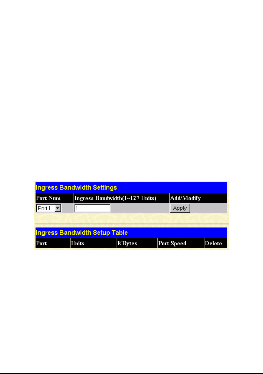
DES-3226 NWay Standalone Fast Ethernet Switch User’s Guide
dynamically create and manage VLANs on switches connected through 802.1Q trunk ports. Click Apply
to let your changes take effect.
The information on the window is described as follows:
• PVID [ 1] – The PVID is used by the port to tag outgoing, untagged packets, and to make filtering
decisions about incoming packets. If the port is specified as tagging, and an untagged packet if
forwarded to the port for transmission, the port will add an 802.1Q tag using the PVID to write the
VID in the tag. When the packet arrives at its destination, the receiving device will use the PVID to
make VLAN forwarding decisions. If a packet is received by the port and ingress filtering is
enabled, the port will compare the VID of the incoming packet to its PVID. If the two are unequal,
the port will drop the packet. If the two are equal, the port will receive the packet.
• Ingress [Off] – Specifies the port to check the VID of incoming packets against its VID or PVID. If
the two are equal, the port will receive the packet. It the two are unequal, the port will drop the
packet. This is used to limit traffic to a single VLAN.
• GVRP [Off] – For each corresponding port, GARP VLAN Registration Protocol can be turned On or
Off.
Port Bandwidth
The following four windows allow you to set and view ingress and egress bandwidth settings.
Ingress Bandwidth
Figure 7-17. Ingress Bandwidth Settings window
To configure ingress bandwidth for a specific port, select the desired port under Port Num and enter a
bandwidth between 1 and 127 in the next field. Click Apply to let your changes take effect. To delete an
entry, click the Delete icon.
108
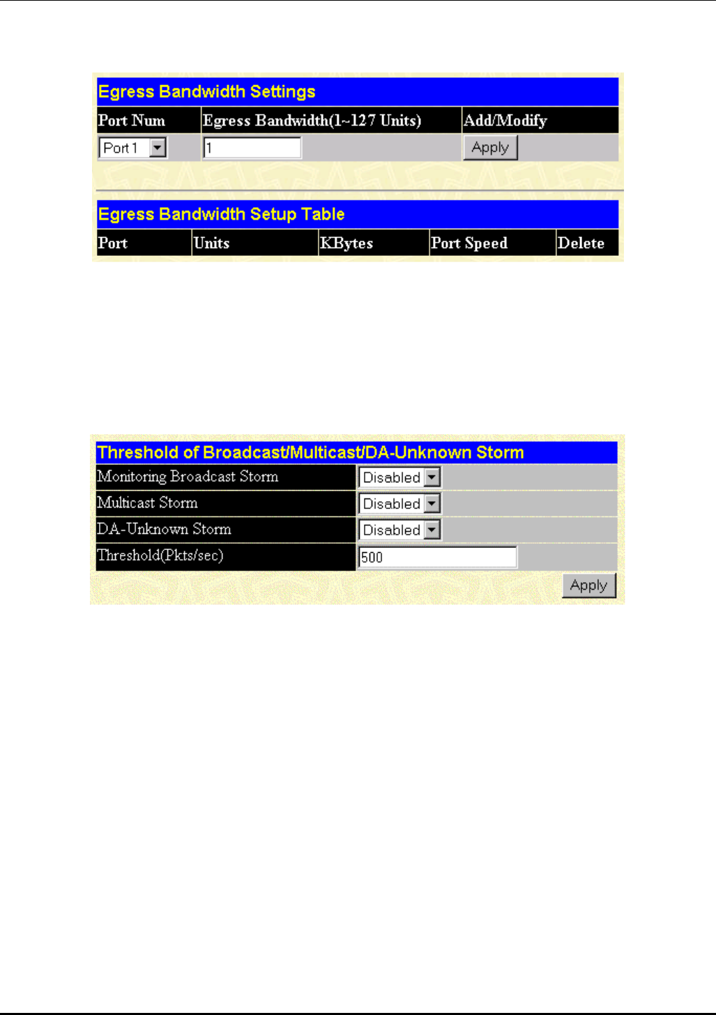
DES-3226 NWay Standalone Fast Ethernet Switch User’s Guide
Egress Bandwidth
Figure 7-18. Egress Bandwidth Settings window
To configure egress bandwidth for a specific port, select the desired port under Port Num and enter a
bandwidth between 1 and 127 in the next field. Click Apply to let your changes take effect. To delete an
entry, click the Delete icon.
Threshold of Broadcast
Figure 7-19. Threshold of Broadcast/Multicast/DA-Unknown Storm window
The Switch allows you to set the threshold for three types of storms: broadcast, multicast, and
destination address unknown. The higher the threshold, the more packets the Switch can accept per
second. If the threshold is exceeded, any additional packets received will be dropped. Entering a low
value means packets have a greater chance to exceed the threshold and, thus, be dropped from the
Switch.
To use the features on this window, select Enabled from the drop-down menu, enter a threshold, and
then click Apply.
109
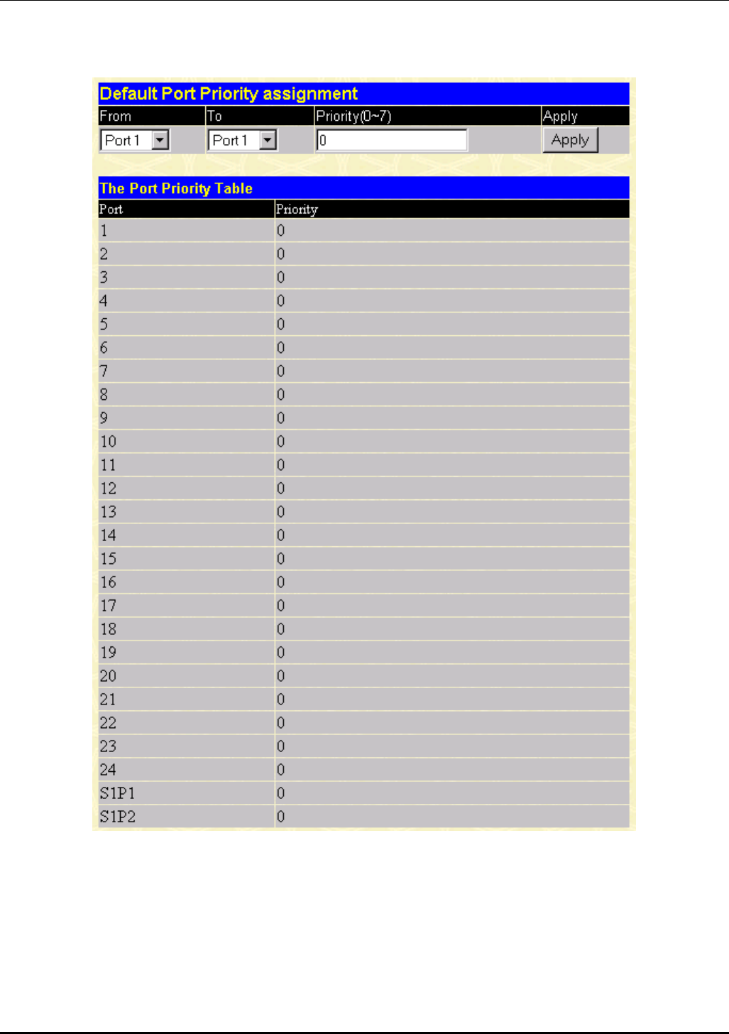
DES-3226 NWay Standalone Fast Ethernet Switch User’s Guide
Port Priority
Figure 7-20. Default Port Priority assignment window
This window allows you to set a default priority for packets that have not already been assigned a
priority value. After filling out the two fields offered, click Apply to let your changes take effect.
110
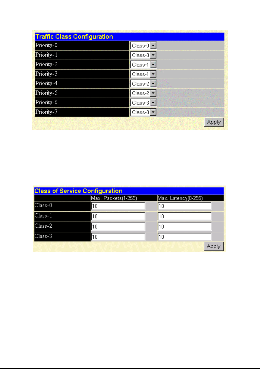
DES-3226 NWay Standalone Fast Ethernet Switch User’s Guide
Class of Traffic
Figure 7-21. Traffic Class Configuration window
This window allows you to configure traffic class priority by specifying the class value, from 0 to 3, of
the Switch’s eight levels of priority. Click Apply to let your changes take effect.
Class of Service
Figure 7-22. Class of Service Configuration window
This window allows you to set the following features:
• Max. Packets – The Class of Service scheduling algorithm starts from the highest CoS for a given
port, sends the maximum number of packets, then moves on to the next lower CoS. The values that
can be entered in this field are from 1 to 255. Entering zero instructs the Switch to continue
processing packets until there are no more packets in the CoS transaction queue.
• Max. Latency – The maximum allowable time a packet will stay in the CoS queue. The packets in
this queue are not delayed more than the maximum allowable latency entered in this field. The
timer is disabled when this field is set to zero. Each unit of this timer is equal to 16 microseconds.
Max. Latency takes precedence over CoS scheduling algorithm.
111
DES-3226 NWay Standalone Fast Ethernet Switch User’s Guide
Port Security
Figure 7-23. Port Security Settings window
To set up security for a port or ports, enter the port or ports in the first two fields, change the Admin
State to Enabled, enter the maximum number of addresses, the desired Mode, and then click Apply.
PAE System Control
The Port Access Entity Control section allows you to use the Switch’s 802.1X port-based authentication
feature.
112
DES-3226 NWay Standalone Fast Ethernet Switch User’s Guide
Configure Authenticator
Figure 7-24. 802.1X Authenticator Settings window
This window allows you to set the following features:
• From [ ] To [ ] – Enter the port or ports to be set.
• AdmDir [both] – Sets the administrative-controlled direction to either in or both. If in is selected,
control is only exerted over incoming traffic through the port you selected in the first field. If both is
selected, control is exerted over both incoming and outgoing traffic through the controlled port
selected in the first field.
113

DES-3226 NWay Standalone Fast Ethernet Switch User’s Guide
• PortControl [auto] – This allows you to control the port authorization state. Select forceAuthorized
to disable 802.1X and cause the port to transition to the authorized state without any
authentication exchange required. This means the port transmits and receives normal traffic
without 802.1X-based authentication of the client. If forceUnauthorized is selected, the port will
remain in the unauthorized state, ignoring all attempts by the client to authenticate. The switch
cannot provide authentication services to the client through the interface. The third option is auto.
This enables 802.1X and causes the port to begin in the unauthorized state, allowing only EAPOL
frames to be sent and received through the port. The authentication process begins when the link
state of the port transitions from down to up, or when an EAPOL-start frame is received. The switch
then requests the identity of the client and begins relaying authentication messages between the
client and the authentication server.
• TxPeriod [30 ] – This sets the TxPeriod of time for the authenticator PAE state machine. This value
determines the period an EAP Request/Identity packet is transmitted to the client.
• QuietPeriod [60 ] – This allows you to set the number of seconds that the switch remains in the
quiet state following a failed authentication exchange with the client.
• SuppTimeout [30 ] – This value determines timeout conditions in the exchanges between the
Authenticator and the client.
• ServerTimeout [30 ] – This value determines timeout conditions in the exchanges between the
Authenticator and the client.
• MaxReq [2 ] – The maximum number of times that the switch will retransmit an EAP Request
packet to the client before it times out the authentication session.
• ReAuthPeriod [3600 ] – A constant that defines a nonzero number of seconds between periodic
reauthentications of the client.
• ReAuth [Disabled] – Determines whether regular reauthentication will take place on this port.
114
DES-3226 NWay Standalone Fast Ethernet Switch User’s Guide
Port Authenticating Settings
Figure 7-25. 802.1X Capability Settings window
To set up the Switch’s 802.1X port-based authentication, select which ports are to be configured in the
From and To fields. Next, enable the ports by selecting Authenticator from the drop-down menu under
Capability. Click Apply to let your change take effect.
115
DES-3226 NWay Standalone Fast Ethernet Switch User’s Guide
Initialize Ports(s)
Figure 7-26. Initialize Port window
This window allows you to initialize a port or group of ports. The Initialize Port Table in the bottom half
of the window displays the current status of the port(s) once you have clicked Apply.
This window displays the following information:
• Port – The port number.
• AuthState – The Authenticator PAE State will display one of the following: Initialize,
Disconnected, Connecting, Authenticating, Authenticated, Aborting, Held, ForceAuth, ForceUnauth,
and N/A.
• BackendState – The Backend Authentication State will display one of the following: Request,
Response, Success, Fail, Timeout, Idle, Initialize, and N/A.
• AdmDir – The Administrative Controlled Directions are both and in.
• OprDir – The Operational Controlled Directions are both and in.
• PortStatus – The status of the controlled port can be authorized, unauthorized, or N/A.
• PortControl – The controlled port can be forceUnauthorized, auto, or forceAuthorized.
Reauthenticate Ports(s)
Figure 7-27. Reauthenticate Port window
This window allows you to reauthenticate a port or group of ports. The Reauthenticate Port Table
displays the current status of the port(s) once you have clicked Apply.
This window displays the following information:
116
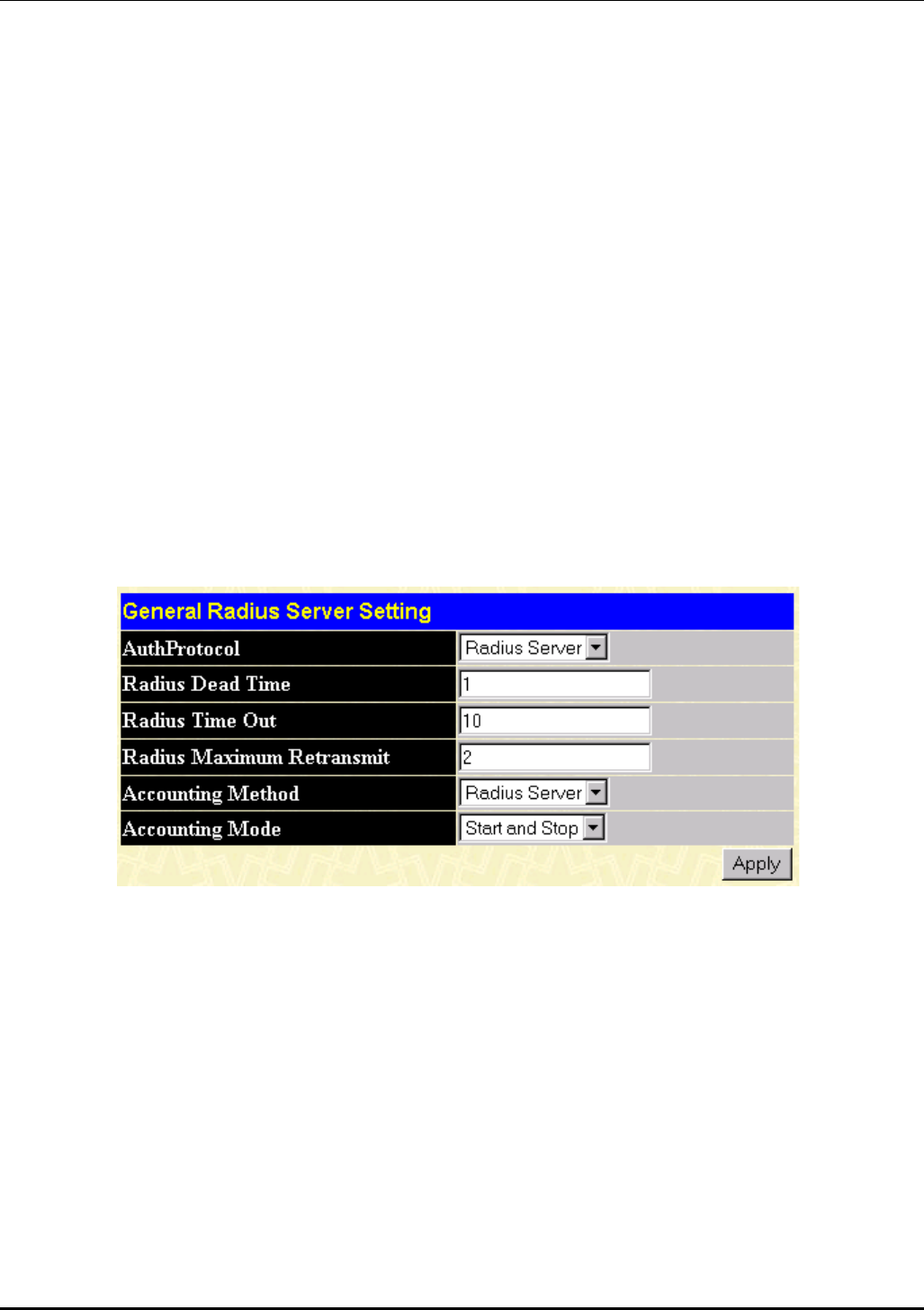
DES-3226 NWay Standalone Fast Ethernet Switch User’s Guide
• Port – The port number.
• AuthState – The Authenticator PAE State will display one of the following: Initialize,
Disconnected, Connecting, Authenticating, Authenticated, Aborting, Held, ForceAuth, ForceUnauth,
and N/A.
• BackendState – The Backend Authentication State will display one of the following: Request,
Response, Success, Fail, Timeout, Idle, Initialize, and N/A.
• AdmDir – The Administrative Controlled Directions are both and in.
• OprDir – The Operational Controlled Directions are both and in.
• PortStatus – The status of the controlled port can be authorized, unauthorized, or N/A.
• PortControl – The controlled port can be forceUnauthorized, auto, or forceAuthorized.
Radius Server
The RADIUS feature of the switch allows you to facilitate centralized user administration as well as
providing protection against a sniffing, active hacker. The Web Manager offers three windows.
General Radius Server
Figure 7-28. General Radius Server Setting window
This window allows you to set the following features:
• AuthProtocol [Radius Server] – Toggle between the authentication protocol options: Radius Server
(Support EAP) and Local.
• Radius Dead Time [1 ] – This specifies the number of minutes a RADIUS server which is not
responding to authentication requests is considered unavailable and is passed over by further
requests for RADIUS authentication.
• Radius Time Out [10 ] – This specifies the number of seconds NAS waits for a reply to a RADIUS
request before transmitting the request.
• Radius Maximum Retransmit [2 ] –This specifies the number of times NAS transmits each
RADIUS request to the server before giving up.
117
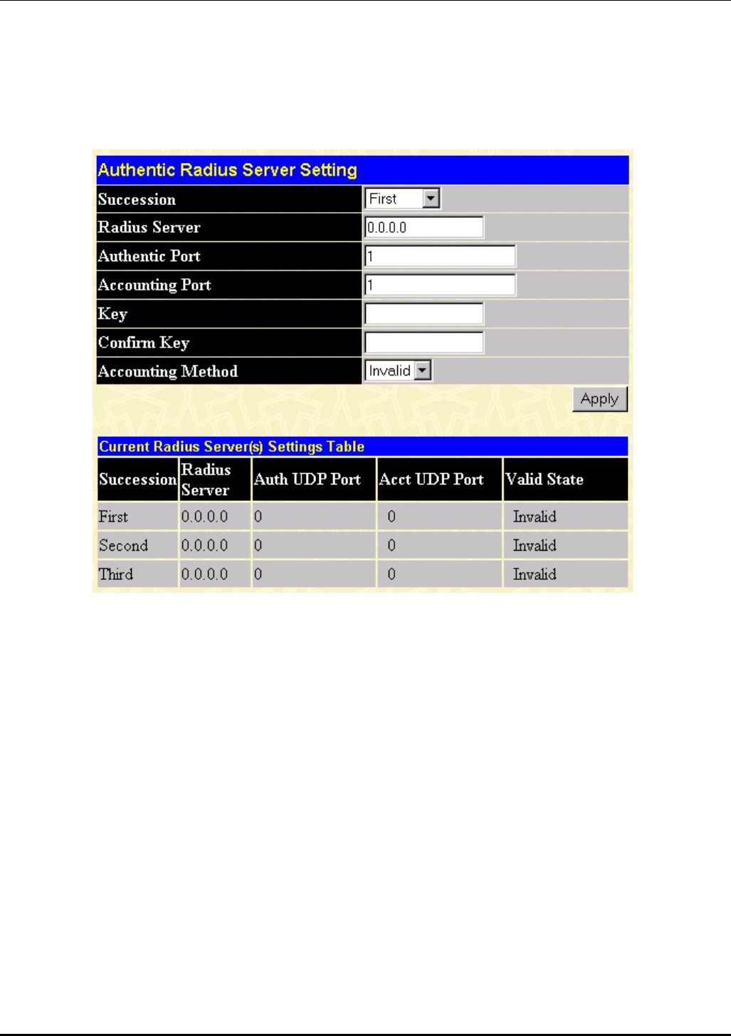
DES-3226 NWay Standalone Fast Ethernet Switch User’s Guide
• Accounting Method [Radius Server] – To use a RADIUS Server, toggle from None to Radius Server.
• Accounting Mode [Start and Stop] – Select the desired method: Start and Stop, Stop only, or None.
Authentic Radius Server
Figure 7-29. Authentic Radius Server Setting window
This window allows you to set the following features:
• Succession [First ] – Choose the desired RADIUS server to configure: First, Second or Third.
• Radius Server [0.0.0.0] – Set the RADIUS server IP.
• Authentic Port [ 0 ] – Set the RADIUS authentic server(s) UDP port. The default is 1813.
• Accounting Port – Set the RADIUS account server(s) UDP port. The default is 1813.
• Key – Set the key the same as that of the RADIUS server.
• Confirm Key – Confirm the shared key is the same as that of the RADIUS server.
• Accounting Method [Invalid] – This allows you to set the RADIUS server as Valid or Invalid.
118
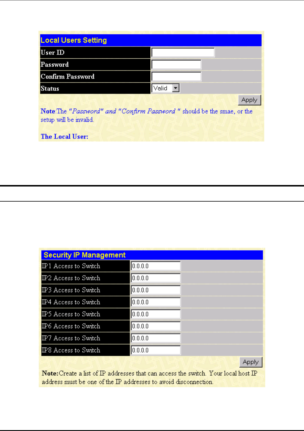
DES-3226 NWay Standalone Fast Ethernet Switch User’s Guide
Local User
Figure 7-30. Local Users Setting window
The fields on this window allow you to add or remove local users.
Management
This category includes: Security IP, SNMP Manager, Trap Manager, and User Accounts.
Security IP
Figure 7-31. Security IP Management window
Use this window to specify IP addresses that are allowed to access the Switch.
119
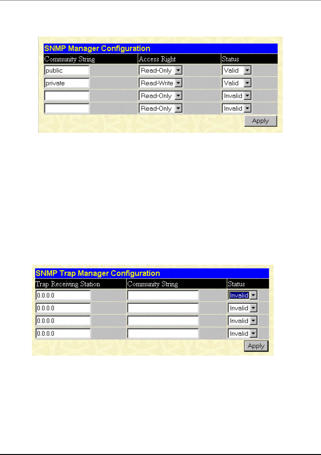
DES-3226 NWay Standalone Fast Ethernet Switch User’s Guide
SNMP Manager
Figure 7-32. SNMP Manager Configuration window
To use the functions on this window, enter the appropriate SNMP information. You may enter up
to four entries. Click Apply to put the settings into effect.
The Community String information is described as follows:
• Community String – A user-defined SNMP community name.
• Access Right – The permitted access of Read-Only or Read-Write using the SNMP community
name.
• Status – Option to set the current community string to Valid or Invalid.
Trap Manager
Figure 7-33. SNMP Trap Manager Configuration window
A trap receiving station is a device that constantly runs a network management application to
receive and store traps. You may enter up to four entries. Click Apply to put the settings into
effect.
The information is described as follows:
• Trap Receiving Station [0.0.0.0] – The IP address of the trap receiving station.
• Community String – A user-defined SNMP community name.
120
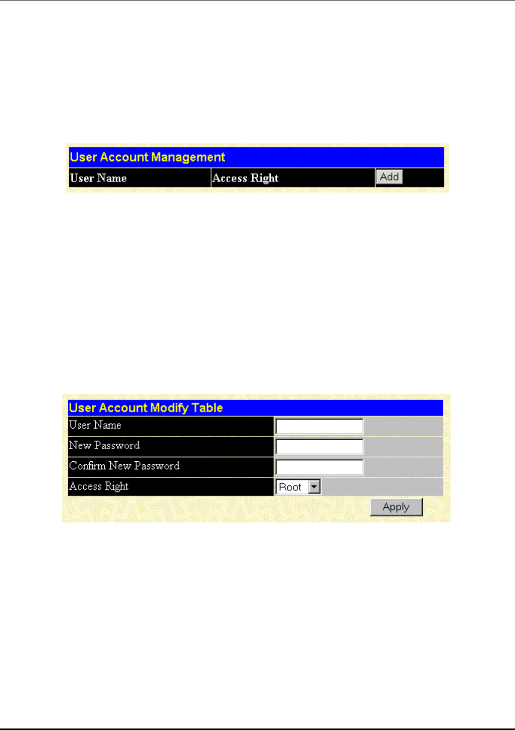
DES-3226 NWay Standalone Fast Ethernet Switch User’s Guide
• Status [Invalid] – Option to set the trap receiving station to Valid or Invalid.
User Accounts
The Switch allows you to set up and manage user accounts in the following two windows.
User Account Management
Figure 7-34. User Account Management window
The information on the window is described as follows:
• User Name – Displays all current users for the Switch.
• Access Right – Displays the current access level assigned to each corresponding user. There are
three access levels: User, User+, and Root. A Root user has full read/write access, while a User has
read only access. A User+ has the same privileges as a User, but with the added ability to restart
the Switch.
• Add – Select this hyperlink to add a new user to the table.
User Account Modify Table
Figure 7-35. User Account Modify Table window
To add or delete a User Account, fill in the appropriate information in the User Name, New
Password, and Confirm New Password fields. Then select the desired access, Root, User or User+,
in the Access Right control and click Apply.
The information on the window is described as follows:
• User Name – Enter a user name in this field.
• New Password – Enter the desired new password in this field.
• Confirm New Password – Enter the new password a second time.
121
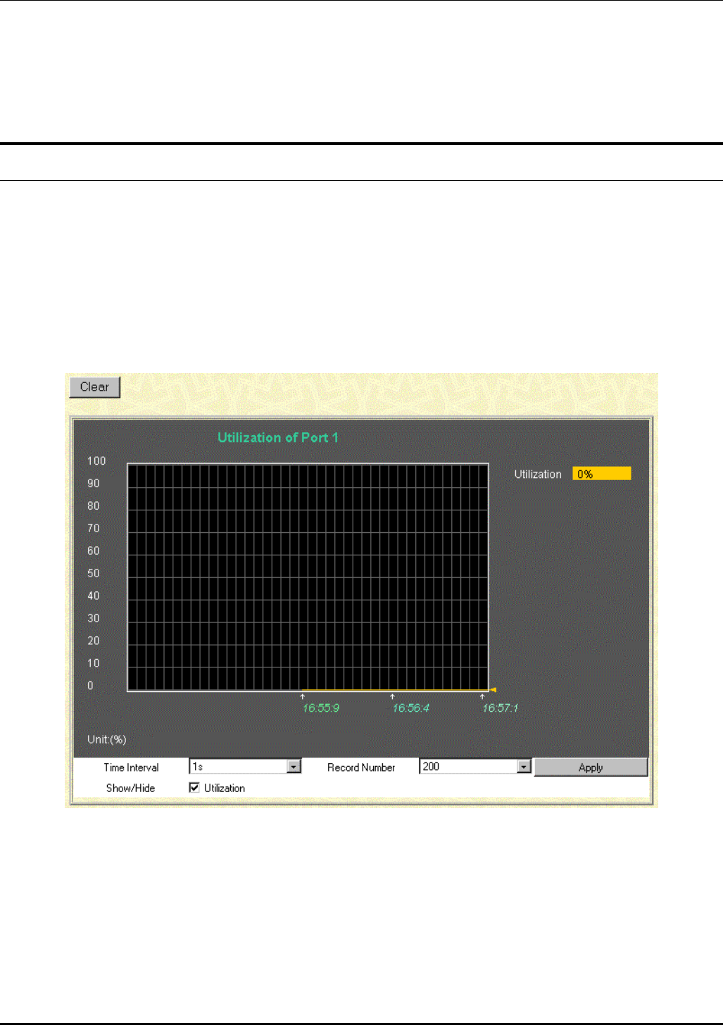
DES-3226 NWay Standalone Fast Ethernet Switch User’s Guide
• Access Right [Root] – Displays the current access level assigned to each corresponding user. There
are three access levels: User, User+, and Root. A Root user has full read/write access, while a User
has read only access. A User+ has the same privileges as a User, but with the added ability to
restart the Switch.
Monitoring
This category includes: Port Utilization, Packets (Received (RX), UMB_cast (RX), and Transmitted
(TX)), Errors (Received (RX) and Transmitted (TX)), Size (Received (RX)), MAC Address, IGMP
Snooping, Dynamic Group Registration, VLAN Status, and Port Access Control, as well secondary
screens.
Port Utilization
The Switch can display the utilization percentage of a specified port in the window below.
Figure 7-36. Utilization window
The information is described as follows:
• Time Interval [1s ]– Select the desired setting between 1s and 60s, where “s” stands for
seconds. The default value is one second.
• Record Number [200] – Select number of times the Switch will be polled between 20 and 200.
The default value is 20.
122
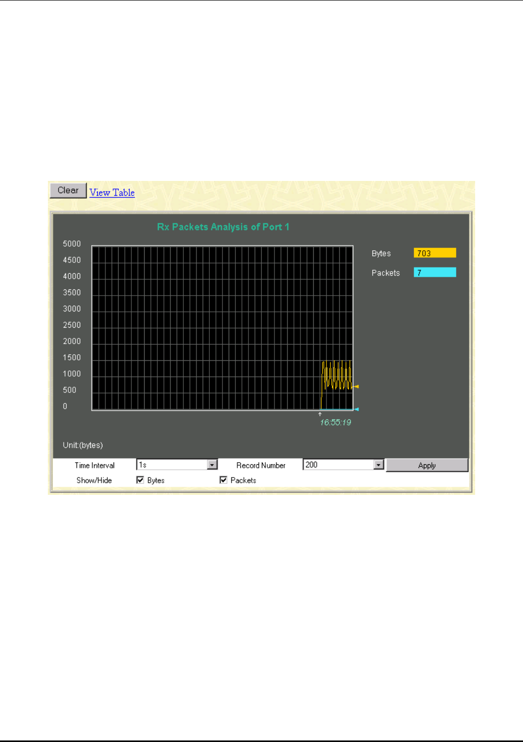
DES-3226 NWay Standalone Fast Ethernet Switch User’s Guide
• Show/Hide – Check whether or not to display Utilization.
• Clear – Clicking this button clears all statistics counters on this window.
Packets
The Web Manager allows various packet statistics to be viewed as either a line graph or a table. The six
windows offered are as follows:
Received (RX)
Figure 7-37. Rx Packets Analysis window (Line Chart)
123
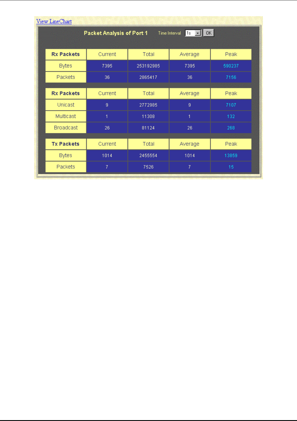
DES-3226 NWay Standalone Fast Ethernet Switch User’s Guide
Figure 7-38. Rx Packets Analysis window (Table)
The information is described as follows:
• Time Interval [1s ] – Select the desired setting between 1s and 60s, where “s” stands for
seconds. The default value is one second.
• Record Number [200 ] – Select number of times the Switch will be polled between 20 and 200.
The default value is 20.
• Bytes – Counts the number of bytes received on the port.
• Packets – Counts the number of packets received on the port.
• Show/Hide – Check whether or not to display Bytes and Packets.
• Clear – Clicking this button clears all statistics counters on this window.
• View Table – Clicking this button instructs the Switch to display a table rather than a line
graph.
• View Line Chart – Clicking this button instructs the Switch to display a line graph rather than a
table.
124
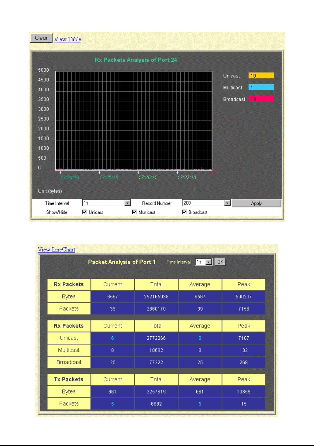
DES-3226 NWay Standalone Fast Ethernet Switch User’s Guide
UMB-cast (RX)
Figure 7-39. Rx Packets Analysis window for UMB (Line Chart)
Figure 7-40. Rx Packets Analysis window for MBU (Table)
125
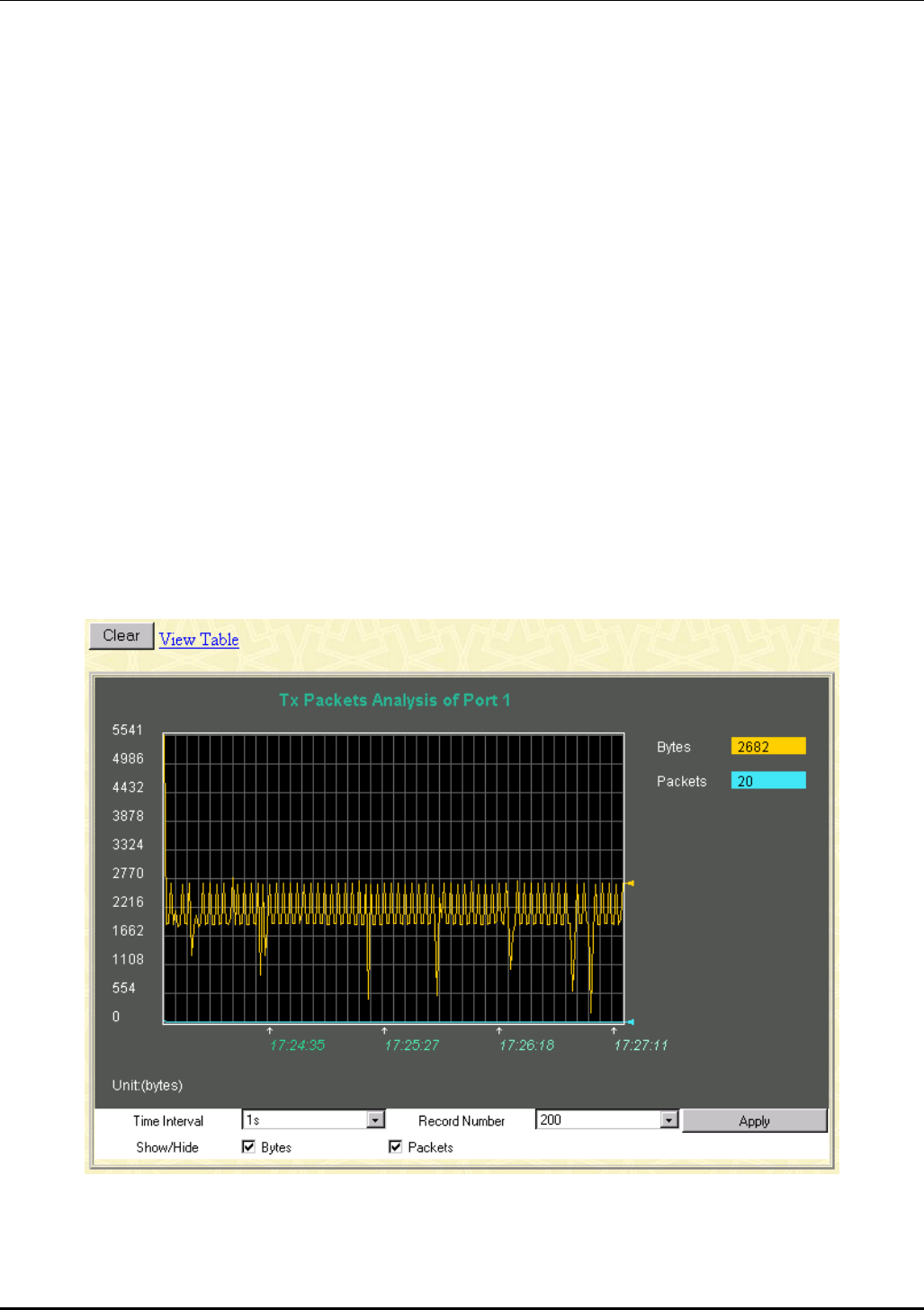
DES-3226 NWay Standalone Fast Ethernet Switch User’s Guide
The information is described as follows:
• Time Interval [1s ] – Select the desired setting between 1s and 60s, where “s” stands for
seconds.
• Record Number [200 ] – Select number of times the Switch will be polled between 20 and 200.
• Unicast – Counts the total number of good packets that were received by a unicast address.
• Multicast – Counts the total number of good packets that were received by a multicast
address.
• Broadcast – Counts the total number of good packets that were received by a broadcast
address.
• Show/Hide – Check whether or not to display Multicast, Broadcast, and Unicast Packets.
• Clear – Clicking this button clears all statistics counters on this window.
• View Table – Clicking this button instructs the Switch to display a table rather than a line
graph.
• View Line Chart – Clicking this button instructs the Switch to display a line graph rather than a
table.
Transmitted (TX)
Figure 7-41. Tx Packets Analysis window (Line Chart)
126
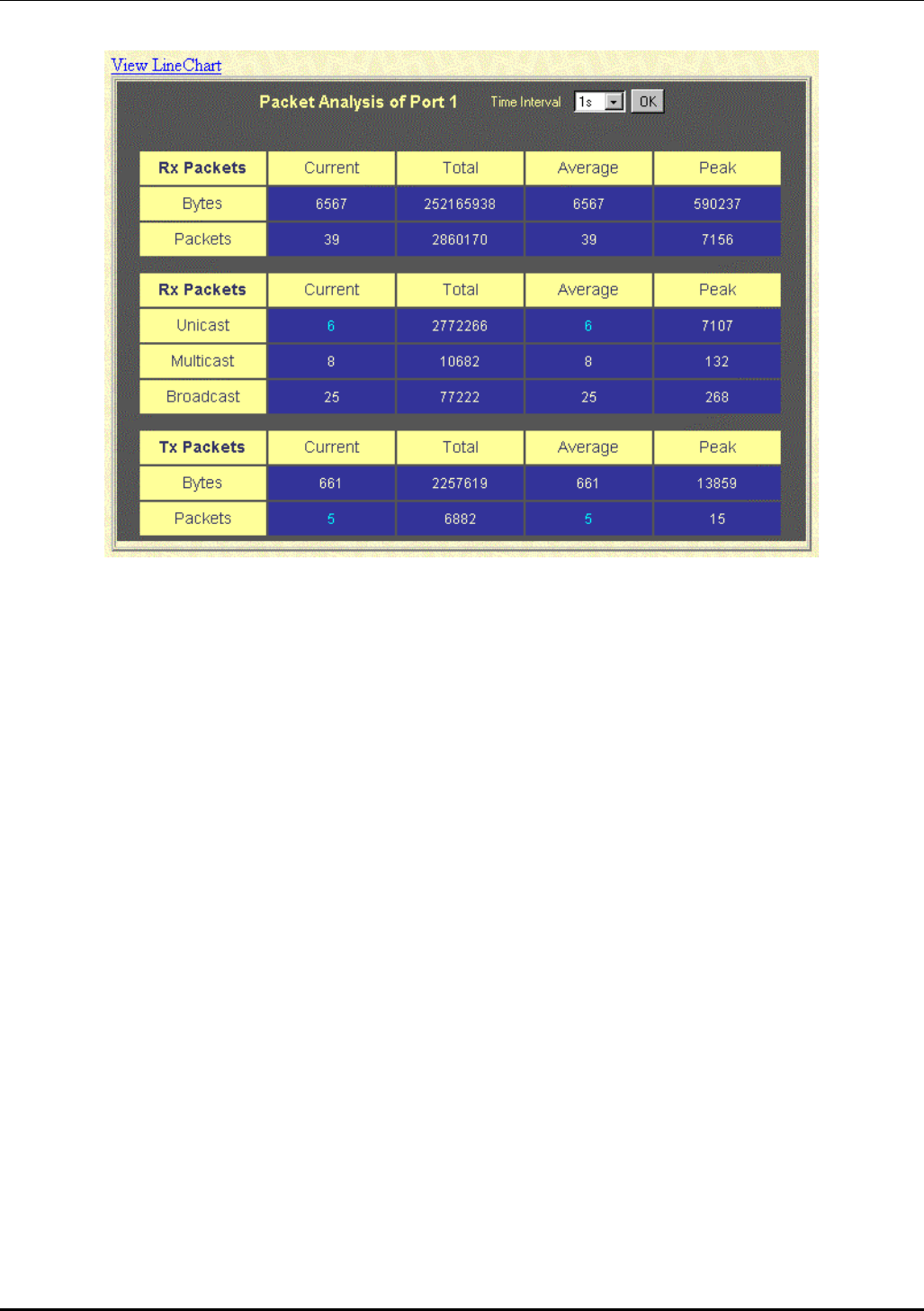
DES-3226 NWay Standalone Fast Ethernet Switch User’s Guide
Figure 7-42. Tx Packets Analysis window (Table)
The information is described as follows:
• Time Interval [1s ] – Select the desired setting between 1s and 60s, where “s” stands for
seconds. The default value is one second.
• Record Number [200 ] – Select number of times the Switch will be polled between 20 and 200.
The default value is 200.
• Bytes – Counts the number of bytes successfully sent from the port.
• Packets – Counts the number of packets successfully sent on the port.
• Show/Hide – Check whether or not to display Bytes and Packets.
• Clear – Clicking this button clears all statistics counters on this window.
• View Table – Clicking this button instructs the Switch to display a table rather than a line
graph.
• View Line Chart – Clicking this button instructs the Switch to display a line graph rather than a
table.
Errors
The Web Manager allows port error statistics compiled by the Switch’s management agent to be viewed
as either a line graph or a table. The four windows offered are as follows:
127
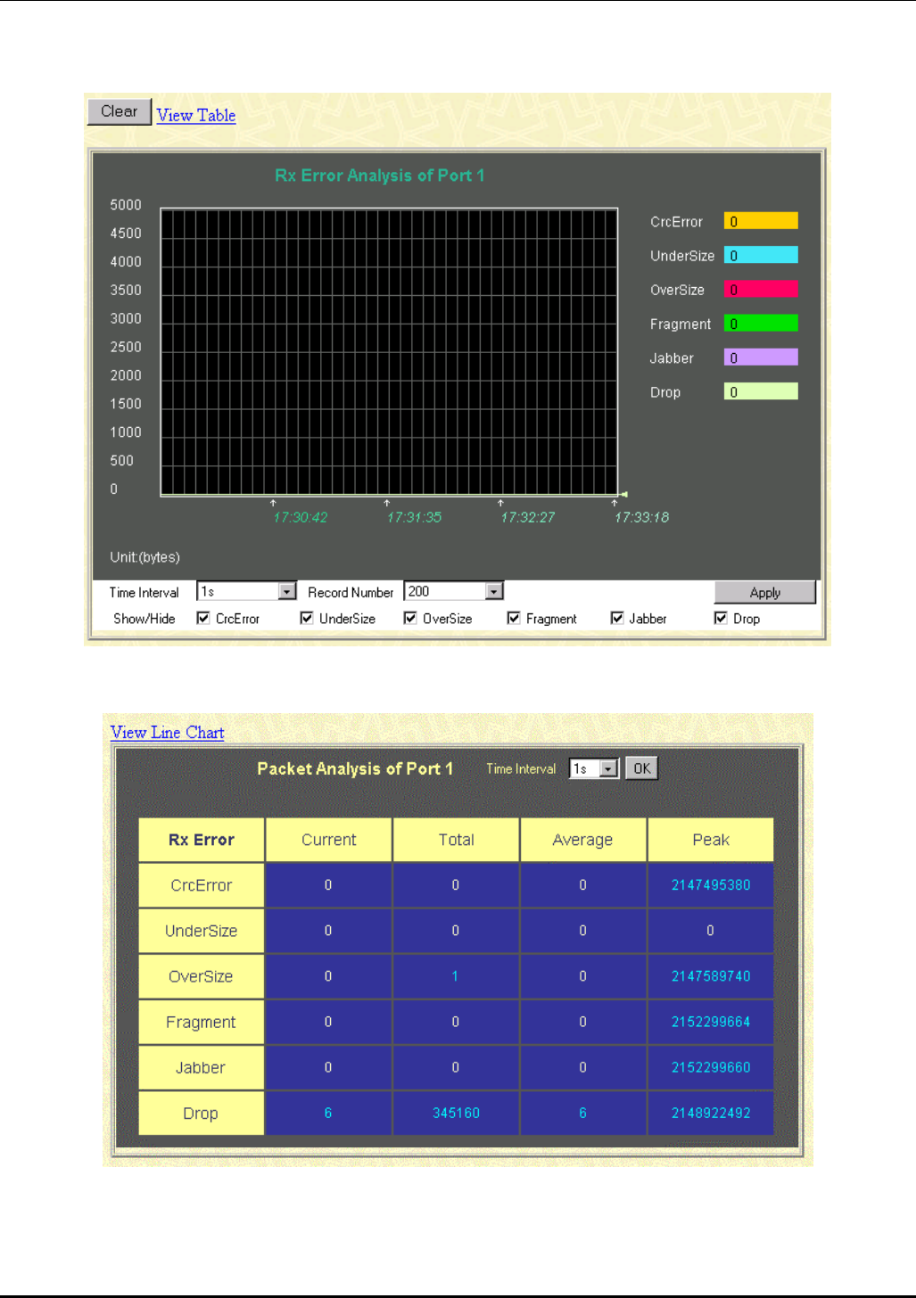
DES-3226 NWay Standalone Fast Ethernet Switch User’s Guide
Received (RX)
Figure 7-43. Rx Error Analysis window (Line Chart)
Figure 7-44. Rx Error Analysis window (Table)
The information is described as follows:
128

DES-3226 NWay Standalone Fast Ethernet Switch User’s Guide
• Time Interval [1s ] – Select the desired setting between 1s and 60s, where “s” stands for
seconds. The default value is one second.
• Record Number [200 ]– Select number of times the Switch will be polled between 20 and 200.
The default value is 200.
• CRCError – Counts otherwise valid frames that did not end on a byte (octet) boundary.
• UnderSize – The number of frames detected that are less than the minimum permitted frame
size of 64 bytes and have a good CRC. Undersize frames usually indicate collision fragments, a
normal network occurrence.
• OverSize – Counts packets received that were longer than 1518 octets, or if a VLAN frame,
1522 octets and less than the MAX_PKT_LEN. Internally, MAX_PKT_LEN is equal to 1522.
• Fragment – The number of packets less than 64 bytes with either bad framing or an invalid
CRC. These are normally the result of collisions.
• Jabber – The number of frames with lengths more than the MAX_PKT_LEN bytes. Internally,
MAX_PKT_LEN is equal to 1522.
• Drop – The number of frames which are dropped by this port since the last Switch reboot.
• Show/Hide – Check whether or not to display CrcError, UnderSize, OverSize, Fragment,
Jabber, and Drop errors.
• Clear – Clicking this button clears all statistics counters on this window.
• View Table – Clicking this button instructs the Switch to display a table rather than a line
graph.
• View Line Chart – Clicking this button instructs the Switch to display a line graph rather than a
table.
129
DES-3226 NWay Standalone Fast Ethernet Switch User’s Guide
Transmitted (TX)
Figure 7-45. Tx Error Analysis window (Line Chart)
Figure 7-46. Tx Error Analysis window (Table)
The information is described as follows:
130

DES-3226 NWay Standalone Fast Ethernet Switch User’s Guide
• Time Interval [1s ] – Select the desired setting between 1s and 60s, where “s” stands for
seconds. The default value is one second.
• Record Number [200 ] – Select number of times the Switch will be polled between 20 and 200.
The default value is 200.
• ExDefer – Counts the number of frames for which the first transmission attempt on a
particular interface was delayed because the medium was busy.
• CRCError – Counts otherwise valid frames that did not end on a byte (octet) boundary.
• LateColl – Counts the number of times that a collision is detected later than 512 bit-times into
the transmission of a packet.
• Show/Hide – Check whether or not to display ExDefer, CrcError, and LateColl errors.
• Clear – Clicking this button clears all statistics counters on this window.
• View Table – Clicking this button instructs the Switch to display a table rather than a line
graph.
• View Line Chart – Clicking this button instructs the Switch to display a line graph rather than a
table.
Size
The Web Manager allows packets received by the Switch, arranged in six groups, to be viewed as either
a line graph or a table. The two windows offered are as follows:
131
DES-3226 NWay Standalone Fast Ethernet Switch User’s Guide
Packet Size
Figure 7-47. Tx/Rx Size Analysis window (Line Chart)
Figure 7-48. Packet Analysis window (Table)
The information is described as follows:
132

DES-3226 NWay Standalone Fast Ethernet Switch User’s Guide
• Time Interval [1s ] – Select the desired setting between 1s and 60s, where “s” stands for
seconds. The default value is one second.
• Record Number [200] – Select number of times the Switch will be polled between 20 and 200.
The default value is 200.
• 64 – The total number of packets (including bad packets) received that were 64 octets in length
(excluding framing bits but including FCS octets).
• 65-127 – The total number of packets (including bad packets) received that were between 65
and 127 octets in length inclusive (excluding framing bits but including FCS octets).
• 128–255 – The total number of packets (including bad packets) received that were between
128 and 255 octets in length inclusive (excluding framing bits but including FCS octets).
• 256-511 – The total number of packets (including bad packets) received that were between
256 and 511 octets in length inclusive (excluding framing bits but including FCS octets).
• 512-1023 – The total number of packets (including bad packets) received that were between
512 and 1023 octets in length inclusive (excluding framing bits but including FCS octets).
• 1024-1518 – The total number of packets (including bad packets) received that were between
1024 and 1518 octets in length inclusive (excluding framing bits but including FCS octets).
• Show/Hide – Check whether or not to display 64, 65-127, 128-255, 256-511, 512-1023, and
1024-1518 packets received.
• Clear – Clicking this button clears all statistics counters on this window.
• View Table – Clicking this button instructs the Switch to display a table rather than a line
graph.
• View Line Chart – Clicking this button instructs the Switch to display a line graph rather than a
table.
MAC Address
The Web Manager allows the Switch’s MAC address table (sometimes referred to as a forwarding table)
to be viewed:
133
DES-3226 NWay Standalone Fast Ethernet Switch User’s Guide
134
Figure 7-49. MAC Address Table window
The information is described as follows:
• Search by VLAN ID – Allows the forwarding table to be browsed by VLAN ID (VID).
• Search by MAC Address – Allows the forwarding table to be browsed by MAC Address.
• Search by Port – Allows the forwarding table to be browsed by port number.
• Jump – Allows the user to move to a sector of the database corresponding to a user defined port,
VLAN, or MAC address.
• Find – Click the icon to find the data entry.
DES-3226 NWay Standalone Fast Ethernet Switch User’s Guide
• Clear All – Clears all forwarding table entries.
• Clear By Port – Clears the forwarding table entries that have the entered port number.
• VID – The VLAN ID of the VLAN the port is a member of.
• MAC Address – The MAC address entered into the address table.
• Port – The port that the MAC address above corresponds to.
• Learned – How the switch discovered the MAC address. The possible entries are Dynamic, Self,
and Static.
• Next – Click this button to view the next page of the address table.
IGMP Snooping
The Switch’s IGMP snooping table can be browsed using the Web Manager. The table is displayed by
VLAN ID (VID).
Figure 7-50. IGMP Snooping Table window
The information is described as follows:
• VID –VLAN ID of the VLAN for which the IGMP Snooping table is to be displayed.
• Search – Click on the View button to display the IGMP Snooping Table for the current VID.
• Multicast Group – The IP address of a multicast group learned by IGMP snooping.
• MAC Address – The corresponding MAC address learned by IGMP snooping.
• Port Map – Displays the ports that have forwarded multicast packets.
• Reports – The number of IGMP reports for the listed source.
Dynamic Group Registration
This read-only table contains filtering information for VLANs configured into the bridge by (local or
network) management, or learned dynamically, specifying the set of ports to which frames received on a
VLAN for this FDB and containing a specific Group destination address are allowed to be forwarded.
135
DES-3226 NWay Standalone Fast Ethernet Switch User’s Guide
Figure 7-51. Dynamic Group Registration Table window
VLAN Status
This read-only table displays VLAN multicast information.
Figure 7-53. VLAN Status window
The information is described as follows:
• VID –VLAN ID of the VLAN for which the multicast table is displayed.
• Multicast Group – The IP address of a multicast group learned through multicasting.
• Static Port List – Displays the ports that have forwarded multicast packets.
Port Access Control
There are five windows that comprise the 802.1X port-based authentication section.
136
DES-3226 NWay Standalone Fast Ethernet Switch User’s Guide
Authenticator State
Figure 7-53. Authenticator Status window
This window displays the Authenticator Status for an individual port. To select a port, click a port on
the front panel display. A polling interval between 1 and 60 seconds can be set using the drop-down
menu at the top of the window.
The information on this window is described as follows:
• AuthState – The Authenticator PAE state value can be: Initialize, Disconnected, Connecting,
Authenticating, Authenticated, Aborting, Held, Force_Auth, Force_Unauth, or N/A. N/A (Not Available)
indicates that the port’s authenticator capability is disabled.
• BackendState – The Backend Authentication state can be Request, Response, Success, Fail,
Timeout, Idle, Initialize, or N/A. N/A indicates that the port’s authenticator capability is disabled.
• AdmDir – Admin Controlled Directions can be either both or in.
• OprDir – Oper Controlled Directions can be either both or in.
• PortStatus – Auth Controlled Port Status can be Authorized, Unauthorized, or N/A.
• Port Control – Auth Controlled Port Control can be ForceAuthorized, ForceUnauthorized, or Auto.
137
DES-3226 NWay Standalone Fast Ethernet Switch User’s Guide
Authenticator Statistics
Figure 7-54. Authenticator Statistics window
This window displays the Authenticator Statistics for an individual port. To select a port, click a port on
the front panel display. A polling interval between 1 and 60 seconds can be set using the drop-down
menu at the top of the window. Clicking the Clear button resets these statistics counters.
The information on this window is described as follows:
• Tx ReqId – The number of EAP Req/Id frames that have been transmitted by this Authenticator.
• Tx Req – The number of EAP Request frames (other than Rq/Id frames) that have been transmitted
by this Authenticator.
• Rx Start – The number of EAPOL Start frames that have been received by this Authenticator.
• Rx Logoff – The number of EAPOL Logoff frames that have been received by this Authenticator.
• Rx RespId – The number of EAP Resp/Id frames that have been received by this Authenticator.
• Rx Error – The number of EAPOL frames that have been received by this Authenticator in which
the frame type is not recognized.
138

DES-3226 NWay Standalone Fast Ethernet Switch User’s Guide
Authenticator Session-Counter
Figure 7-55. Authenticator Session Counter window
This window displays the Authenticator Session Counter for an individual port. To select a port, click a
port on the front panel display. A polling interval between 1 and 60 seconds can be set using the drop-
down menu at the top of the window.
The information on this window is described as follows:
• Frames Rx – The number of user data frames received on this Port during the session.
• Frames Tx – The number of user data frames transmitted on this Port during the session.
• UserName – The User Name representing the identity of the client PAE.
• Time – The session time is the duration of time in seconds.
• TerminateCause – The reason for the session termination. This parameter can take the following
values: Client Logoff, Port Failure, Client Restart, Reauthentication Failure, AuthControlledPortControl
set to ForceUnauthorized, Port Re-initialization, Port Administratively Disabled, and Not Terminated Yet.
139
DES-3226 NWay Standalone Fast Ethernet Switch User’s Guide
Radius Authentication
Figure 7-56. show Radius Authentication window
This window displays Radius Authentication information. A polling interval between 1 and 60 seconds
can be set using the drop-down menu at the top of the window.
The information on this window is described as follows:
• Server – The remote RADIUS server IP address.
• UDP Port – The UDP socket port numbers of the RADIUS server.
• Timeouts – The counter of timeouts from RADIUS authentication.
• Requests – The counter of access requests from RADIUS authentication.
• Challenges – The counter of access challenges from RADIUS authentication.
• Accepts – The counter for the number of acceptances from RADIUS authentication.
• Rejects – The counter for the number of rejections from RADIUS authentication.
140
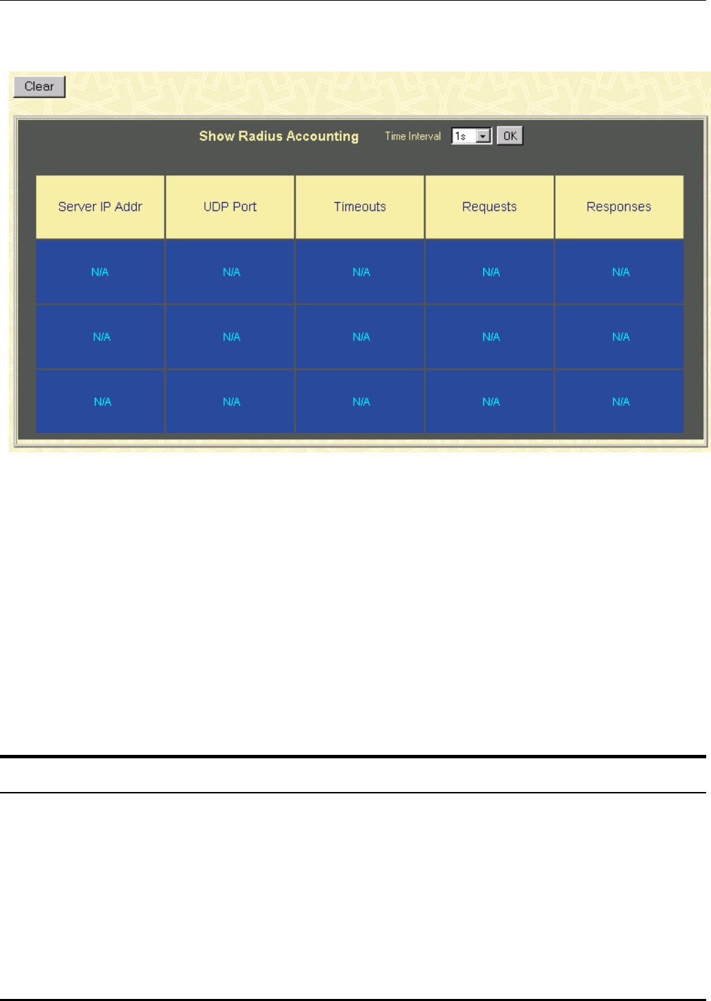
DES-3226 NWay Standalone Fast Ethernet Switch User’s Guide
Radius Accounting
Figure 7-57. show Radius Accounting window
This window displays Radius Accounting information. A polling interval between 1 and 60 seconds can
be set using the drop-down menu at the top of the window.
The information on this window is described as follows:
• Server IP Addr – The IP address of the RADIUS accounting server.
• UDP Port – The UDP socket port number of the RADIUS accounting server.
• Timeouts – The counter of the timeout connections to the RADIUS accounting server.
• Requests – The counter of the requests from the RADIUS accounting server.
• Responses – The counter for the number of rejections from RADIUS accounting server.
Maintenance
This category includes TFTP Services (Update Firmware, Configuration File, Save Settings, and
Save History Log), Switch History, Ping Test, Save Changes, Factory Reset, Restart System,
Connection Timeout, and Logout.
TFTP Services
Trivial File Transfer Protocol (TFTP) services allow the Switch firmware to be upgraded by downloading a
new firmware file from a TFTP server to the Switch. A configuration file can also be loaded into the
141
DES-3226 NWay Standalone Fast Ethernet Switch User’s Guide
Switch, and switch settings can be saved to a TFTP server. In addition, the Switch’s history log can be
uploaded from the Switch to a TFTP server.
Please note that TFTP server software must be running on the management station for the TFTP
services listed here to work.
Update Firmware
Figure 7-58. Update Firmware from Server window
Enter the IP address of the TFTP Server in the Server IP Address field and the complete path and file
name of the firmware file for the Switch. Click Apply to enter the server’s IP address into the Switch’s
RAM (use Save Changes to enter the address into the Switch’s non-volatile RAM). Click Start to initiate
the file transfer.
The information is described as follows:
• Server IP Address – The IP address of the TFTP server.
• File Name – The full file name (including path) of the new firmware file on the TFTP server.
Configuration File
A configuration file can be downloaded from a TFTP server to the Switch. This file is then used by the
Switch to configure itself.
Figure 7-59. Use Configuration File on Server window
Enter the IP address of the TFTP Server in the Server IP Address field and the complete path and file
name of the firmware file for the Switch. Click Apply to enter the server’s IP address into the Switch’s
RAM (use Save Changes to enter the address into the Switch’s non-volatile RAM). Click Start to initiate
the file transfer.
The information is described as follows:
• Server IP Address – The IP address of the TFTP server.
• File Name – The full file name (including path) of the new firmware file on the TFTP server.
142
DES-3226 NWay Standalone Fast Ethernet Switch User’s Guide
Note: Configuration files used in the earlier version of this switch (firmware version 1.0) are not
supported by the present version (firmware version 2.0). The Switch Information window displays
the firmware version.
Save Settings
The Switch’s current settings can be uploaded to a TFTP Server by the Switch’s management agent.
Figure 7-60. Save Settings To TFTP Server window
Enter the IP address of the TFTP Server in the Server IP Address field and the complete path and file
name of the firmware file for the Switch. Click Apply to enter the server’s IP address into the Switch’s
RAM (use Save Changes to enter the address into the Switch’s non-volatile RAM). Click Start to initiate
the file transfer.
Please note that if the user does not save configurations to NV-RAM, the configurations the user is
uploading to a TFTP server will not be saved correctly.
The information is described as follows:
• Server IP Address – The IP address of the TFTP server.
• File Name – The full file name (including path) of the new firmware file on the TFTP server.
Save History Log
The Switch’s management agent can upload its history log file to a TFTP server.
Please note that an empty history file on the TFTP server must exist on the server before the Switch can
upload its history file.
Figure 7-61. Save Switch History To TFTP Server window
Enter the IP address of the TFTP Server in the Server IP Address field and the complete path and file
name of the firmware file for the Switch. Click Apply to enter the server’s IP address into the Switch’s
RAM (use Save Changes to enter the address into the Switch’s non-volatile RAM). Click Start to initiate
the file transfer.
The information is described as follows:
143
DES-3226 NWay Standalone Fast Ethernet Switch User’s Guide
• Server IP Address – The IP address of the TFTP server.
• File Name – The full file name (including path) of the new firmware file on the TFTP server.
Switch History
The Web Manager allows the Switch’s history log, as compiled by the Switch’s management agent, to be
viewed.
Figure 7-62. Switch History window
The Switch can record event information in its own logs, to designated SNMP trap receiving
stations, and to the PC connected to the console manager. Clicking Next at the bottom of the
window will allow you to display all the Switch Trap Logs. Clicking Clear will reset this log.
The information is described as follows:
• Sequence – A counter incremented whenever an entry to the Switch’s history log is made. The
table displays the last entry (highest sequence number) first.
• Time – Displays the time in days, hours, and minutes since the Switch was last restarted.
• Log Text – Displays text describing the event that triggered the history log entry.
144
DES-3226 NWay Standalone Fast Ethernet Switch User’s Guide
Ping Test
The Switch is able to test the connection with another network device using Ping.
Figure 7-63. Ping Test window
Enter the IP address of the network device to be Pinged in the first field and select the number of test
packets to be sent (3 is usually enough). Click Start to initiate the Ping program.
Save Changes
Figure 7-64. Save Configuration window
To save all the changes made in the current session to the Switch’s flash memory, click the Save
Configuration button.
145
DES-3226 NWay Standalone Fast Ethernet Switch User’s Guide
Factory Reset
Figure 7-65. Factory Reset to Default Value window
A remote reset returns the Switch to the initial parameters set at the factory. Click Reset to Factory
Default to reset the Switch.
Restart System
Figure 7-66. Restart System window
To perform a reboot of the Switch, which resets the system, click the Restart button.
146
DES-3226 NWay Standalone Fast Ethernet Switch User’s Guide
Connection Timeout
Figure 7-67. Web Timeout Setup window
To use this Web timeout feature, enter the desired age-out time and then click Apply.
Logout
Figure 7-68. Logout Web Setups window
To exit the setup pages and return to the main page, click Apply.
Help
Click this button to access the online helpfiles for the Switch.
147

DES-3226 NWay Standalone Fast Ethernet Switch User’s Guide
A
TECHNICAL SPECIFICATIONS
General
Standards: IEEE 802.3ab Gigabit Ethernet
IEEE 802.3z Gigabit Ethernet
IEEE 802.3 10BASE-T Ethernet
IEEE 802.3u 100BASE-TX Fast Ethernet
IEEE 802.1 Q VLAN
IEEE 802.3x Full-duplex Flow Control
ANSI/IEEE 802.3 NWay auto-negotiation
Protocols: CSMA/CD
Data Transfer
Rates:
Ethernet
Fast Ethernet
Half-duplex Full-duplex
10 Mbps 20Mbps
100Mbps 200Mbps
Topology: Star
Network Cables:
10BASE-T:
100BASE-TX:
2-pair UTP Cat. 3, 4, 5 (100 m)
EIA/TIA- 568 100-ohm STP (100 m)
2-pair UTP Cat. 5 (100 m)
EIA/TIA-568 100-ohm STP (100 m)
Number of Ports: 24 x 10/100 Mbps NWay ports (DES-3226)
1 or 2 100BASE ports or 2 1000BASE ports (optional)
148

DES-3226 NWay Standalone Fast Ethernet Switch User’s Guide
Physical and Environmental
AC inputs: 100 - 240 VAC, 50/60 Hz (internal universal
power supply)
Power
Consumption:
40 watts maximum
DC fans: 2 built-in 40 x 40 x10 mm fans
Operating
Temperature:
0 to 50 degrees Celsius
Storage
Temperature:
-25 to 55 degrees Celsius
Humidity: Operating: 5% to 95% RH non-condensing;
Storage: 0% to 95% RH non-condensing
Dimensions: 441 mm x 207 mm x 44 mm (1U), 19 inch rack-
mount width
Weight: 2.8 kg
EMI: FCC Class A, CE Class A, VCCI Class A, BSMI
Class A, C-Tick Class A
Safety: CSA
Performance
Transmission Method: Store-and-forward
RAM Buffer: 8 Mbytes per device
Filtering Address
Table:
8K
Packet Filtering/
Forwarding Rate:
Full-wire speed for all connections.
148,800 pps per port (for 100Mbps)
1,488,000 pps per port (for
1000Mbps)
MAC Address Learning: Automatic update.
Forwarding Table Age
Time:
Max age: 10–1000000 seconds.
Default = 300.
149
DES-3226 NWay Standalone Fast Ethernet Switch User’s Guide
B
RJ-45 PIN SPECIFICATION
When connecting the Switch to another switch, a bridge or a hub, a normal cable is necessary. Please
review these products for matching cable pin assignment.
The following diagram and table show the standard RJ-45 receptacle/connector and their pin
assignments for the switch-to-network adapter card connection, and the normal cable for the Switch-to-
switch/hub/bridge connection.
Figure B-1. The standard RJ-45 receptacle/connector
150

DES-3226 NWay Standalone Fast Ethernet Switch User’s Guide
RJ-45 Connector pin assignment
Contact Media Direct Interface
Signal
1 Tx + (transmit)
2 Tx - (transmit)
3 Rx + (receive)
4 Not used
5 Not used
6 Rx - (receive)
7 Not used
8 Not used
Table B-1. The standard Category 3 cable, RJ-45 pin assignment
151

DES-3226 NWay Standalone Fast Ethernet Switch User’s Guide
C
RUNTIME SWITCHING SOFTWARE
DEFAULT SETTINGS
Load mode Ethernet
Configuration update Disable
Firmware update Disable
Out-of-band baud rate 9600
RS232 mode Console
IP address 10.90.90.90
Subnet mask 255.0.0.0
Default gateway 0.0.0.0
BootP service Disable
TFTP server IP address 0.0.0.0
Auto log-out 10 min
User name None
Password None
MAC address aging time 300 secs
IGMP snooping Disable
Switch GVRP Disable
Telnet status Enable
Web status Enable
Device STP Disable
Port STP Enable
Port enable Enable
Group address filter mode Forward all unregistered
Scheduling mechanism for COS queues Strict
GMRP Disable
802.1X Disable
Filtering EAPOL PDU Yes
Bridge max age 20 secs
Bridge hello time 2 secs
Bridge forward delay 15 secs
Bridge priority 32768
Port STP cost 100
Port STP priority 128
NWay Enable
Community string “public”, “private”
VLAN mode IEEE 802.1Q
Management VLAN ID 1
Default port VID 1
Ingress rule checking Disable
Device 802.1X Disable
Port 802.1X Capability None
152

DES-3226 NWay Standalone Fast Ethernet Switch User’s Guide
D
UNDERSTANDING AND
TROUBLESHOOTING THE SPANNING
TREE PROTOCOL
When the spanning-tree algorithm determines a port should be transitioned to the forwarding state, the
following occurs:
• The port is put into the listening state where it receives BPDUs and passes them to the switch’s
CPU. BPDU packets from the CPU are processed. If no BPDUs that suggest the port should go
to the blocking state are received:
• The port waits for the expiration of the forward delay timer. It then moves to the learning state.
• In the learning state, the port learns station location information from the source address of
packets and adds this information to its forwarding database.
• The expiration of forwarding delay timer moves the port to the forwarding state, where both
learning and forwarding are enabled. At this point, packets are forwarded by the port.
Blocking State
A port in the blocking state does not forward packets. When the switch is booted, a BPDU is sent to
each port in the switch putting these ports into the blocking state. A switch initially assumes it is the
root, and then begins the exchange of BPDUs with other switches. This will determine which switch in
the network is the best choice for the root switch. If there is only one switch on the network, no BPDU
exchange occurs, the forward delay timer expires, and the ports move to the listening state. All STP
enabled ports enter the blocking state following switch boot.
A port in the blocking state does the following:
• Discards packets received from the network segment to which it is attached.
• Discards packets sent from another port on the switch for forwarding.
• Does not add addresses to its forwarding database
• Receives BPDUs and directs them to the CPU.
• Does not transmit BPDUs received from the CPU.
• Receives and responds to network management messages.
153
DES-3226 NWay Standalone Fast Ethernet Switch User’s Guide
Listening State
The listening state is the first transition for a port from the blocking state. Listening is an opportunity
for the switch to receive BPDUs that may tell the switch that the port should not continue to transition
to the forwarding state, but should return to the blocking state (that is, a different port is a better
choice).
There is no address learning or packet forwarding from a port in the listening state.
A port in the listening state does the following:
• Discards frames received from the network segment to which it is attached.
• Discards packets sent from another port on the switch for forwarding.
• Does not add addresses to its forwarding database
• Receives BPDUs and directs them to the CPU.
• Processes BPDUs received from the CPU.
• Receives and responds to network management messages.
154
DES-3226 NWay Standalone Fast Ethernet Switch User’s Guide
Learning State
A port in the learning state prepares to participate in frame forwarding. The port enters the learning
state from the listening state.
A port in the learning state does the following:
• Discards frames received from the network segment to which it is attached.
• Discards packets sent from another port on the switch for forwarding.
• Adds addresses to its forwarding database.
• Receives BPDUs and directs them to the CPU.
• Processes and transmits BPDUs received from the CPU.
• Receives and responds to network management messages.
155
DES-3226 NWay Standalone Fast Ethernet Switch User’s Guide
Forwarding State
A port in the forwarding state forwards packets. The port enters the forwarding state from the learning
state when the forward delay timer expires.
A port in the forwarding state does the following:
• Forwards packets received from the network segment to which it is attached.
• Forwards packets sent from another port on the switch for forwarding.
• Incorporates station location information into its address database.
• Receives BPDUs and directs them to the system CPU.
• Receives and responds to network management messages.
Disabled State
A port in the disabled state does not participate in frame forwarding or STP. A port in the disabled state
is virtually non-operational.
156
DES-3226 NWay Standalone Fast Ethernet Switch User’s Guide
A disabled port does the following:
• Discards packets received from the network segment to which it is attached.
• Discards packets sent from another port on the switch for forwarding.
• Does not add addresses to its forwarding database.
• Receives BPDUs, but does not direct them to the system CPU.
• Does not receive BPDUs for transmission from the system CPU.
• Receives and responds to network management messages.
157
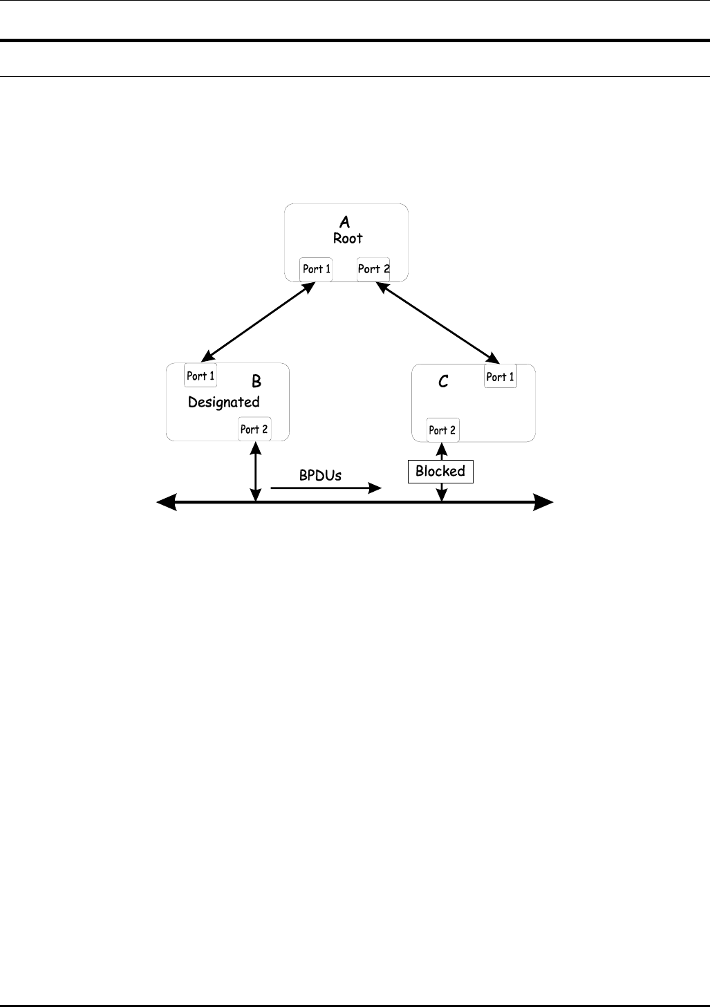
DES-3226 NWay Standalone Fast Ethernet Switch User’s Guide
Troubleshooting STP
Spanning Tree Protocol Failure
A failure in the STA generally leads to a bridging loop. A bridging loop in an STP environment comes
from a port that should be in the blocking state, but is forwarding packets.
In this example, B has been elected as the designated bridge and port 2 on C is in the blocking state.
The election of B as the designated bridge is determined by the exchange of BPDUs between B and C. B
had a better BPDU than C. B continues sending BPDUs advertising its superiority over the other
bridges on this LAN. Should C fail to receive these BPDUs for longer than the MAX AGE (default of 20
seconds), it could start to transition its port 2 from the blocking state to the forwarding state.
It should be noted: A port must continue to receive BPDUs advertising superior paths to remain in the
blocking state.
There are a number of circumstances in which the STA can fail – mostly related to the loss of a large
number of BPDUs. These situations will cause a port in the blocking state to transition to the
forwarding state.
Full/Half Duplex Mismatch
A mismatch in the duplex state of two ports is a very common configuration error for a point-to-point
link. If one port is configured as a full duplex, and the other port is left in auto-negotiation mode, the
second port will end up in half-duplex because ports configured as half- or full-duplex do not negotiate.
158

DES-3226 NWay Standalone Fast Ethernet Switch User’s Guide
In the above example, port 1 on B is configured as a full-duplex port and port 1 on A is either
configured as a half-duplex port, or left in auto-negotiation mode. Because port 1 on B is configured as
a full-duplex port, it does not do the carrier sense when accessing the link. B will then start sending
packets even if A is using the link. A will then detect collisions and begin to run the flow control
algorithm. If there is enough traffic between B and A, all packets (including BPDUs) will be dropped. If
the BPDUs sent from A to B are dropped for longer than the MAX AGE, B will lose its connection to the
root (A) and will unblock its connection to C. This will lead to a data loop.
Unidirectional Link
Unidirectional links can be caused by an undetected failure in one side of a fiber cable, or a problem
with a ports transceiver. Any failure that allows a link to remain up while providing one-way
communication is very dangerous for STP.
In this example, port 2 on B can receive but not transmit packets. Port 2 on C should be in the blocking
state, but since it can no longer receive BPDUs from port 2 on B, it will transition to the forwarding
159

DES-3226 NWay Standalone Fast Ethernet Switch User’s Guide
state. If the failure exists at boot, STP will not converge and rebooting the bridges will have no effect.
(Note: Rebooting would help temporarily in the previous example).
This type of failure is difficult to detect because the Link-state LEDs for Ethernet links rely on the
transmit side of the cable to detect a link. If a unidirectional failure on a link is suspected, it is usually
required to go to the console or other management software and look at the packets received and
transmitted for the port. A unidirectional port will have many packets transmitted but none received, or
vice versa, for example.
Packet Corruption
Packet corruption can lead to the same type of failure. If a link is experiencing a high rate of physical
errors, a large number of consecutive BPDUs can be dropped and a port in the blocking state would
transition to the forwarding state. The blocking port would have to have the BPDUs dropped for 50
seconds (at the default settings) and a single BPDU would reset the timer. If the MAX AGE is set too
low, this time is reduced.
Resource Errors
The DES-3226 performs its switching and routing functions primarily in hardware, using specialized
ASICs. STP is implemented in software and is thus reliant upon the speed of the CPU and other factors
to converge. If the CPU is over-utilized, it is possible that BPDUs may not be sent in a timely fashion.
STP is generally not very CPU intensive and is given priority over other processes, so this type of error is
rare.
It can be seen that very low values for the MAX AGE and the FORWARD DELAY can result in an
unstable spanning tree. The loss of BPDUs can lead to data loops. The diameter of the network can also
cause problems. The default values for STP give a maximum network diameter of about seven. This
means that two switches in the network cannot be more than seven hops apart. Part of this diameter
restriction is the BPDU age field. As BPDUs are propagated from the root bridge to the leaves of the
spanning tree, each bridge increments the age field. When this field is beyond the maximum age, the
packet is discarded. For large diameter networks, STP convergence can be very slow.
Identifying a Data Loop
Broadcast storms have a very similar effect on the network to data loops, but broadcast storm controls
in modern switches have (along with subnetting and other network practices) have been very effective in
controlling broadcast storms. The best way to determine if a data loop exists is to capture traffic on a
saturated link and check if similar packets are seen multiple times.
Generally, if all the users of a given domain are having trouble connecting to the network at the same
time, a data loop can be suspected. The port utilization data in the switch’s console will give unusually
high values in this case.
The priority for most cases is to restore connectivity as soon as possible. The simplest remedy is to
manually disable all of the ports that provide redundant links. Disabling ports one at a time, and then
checking for a restoration of the user’s connectivity will identify the link that is causing the problem, if
time allows. Connectivity will be restored immediately after disabling a data loop.
Avoiding Trouble
Know where the root is located.
160
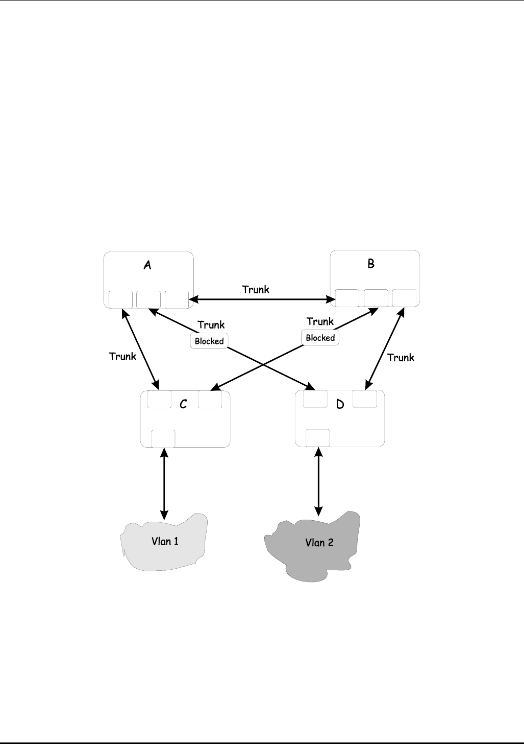
DES-3226 NWay Standalone Fast Ethernet Switch User’s Guide
Although the STP can elect a root bridge, a well-designed network will have an identifiable root for each
VLAN. Careful setup of the STP parameters will lead to the selection of this best switch as the root for
each VLAN. Redundant links can then be built into the network. STP is well suited to maintaining
connectivity in the event of a device failure or removal, but is poorly suited to designing networks.
Know which links are redundant.
Organize the redundant links and tune the port cost parameter of STP to force those ports to be in the
blocking state.
For each VLAN, know which ports should be blocking in a stable network. A network diagram that
shows each physical loop in the network and which ports break which loops is extremely helpful.
Minimize the number of ports in the blocking state.
A single blocking port transitioning to the forwarding state at an inappropriate time can cause a large
part of a network to fail. Limiting the number of blocked ports help to limit the risk of an inappropriate
transition.
This is a common network design. The switches C and D have redundant links to the backbone
switches A and B using trunks. Trunks, by default, carry all the VLAN traffic from VLAN 1 and VLAN 2.
So switch C is not only receiving traffic for VLAN 1, but it is also receiving unnecessary broadcast and
multicast traffic for VLAN 2. It is also blocking one port for VLAN 2. Thus, there are three redundant
paths between switches A and B and two blocked ports per VLAN. This increases the chance of a data
loop.
161
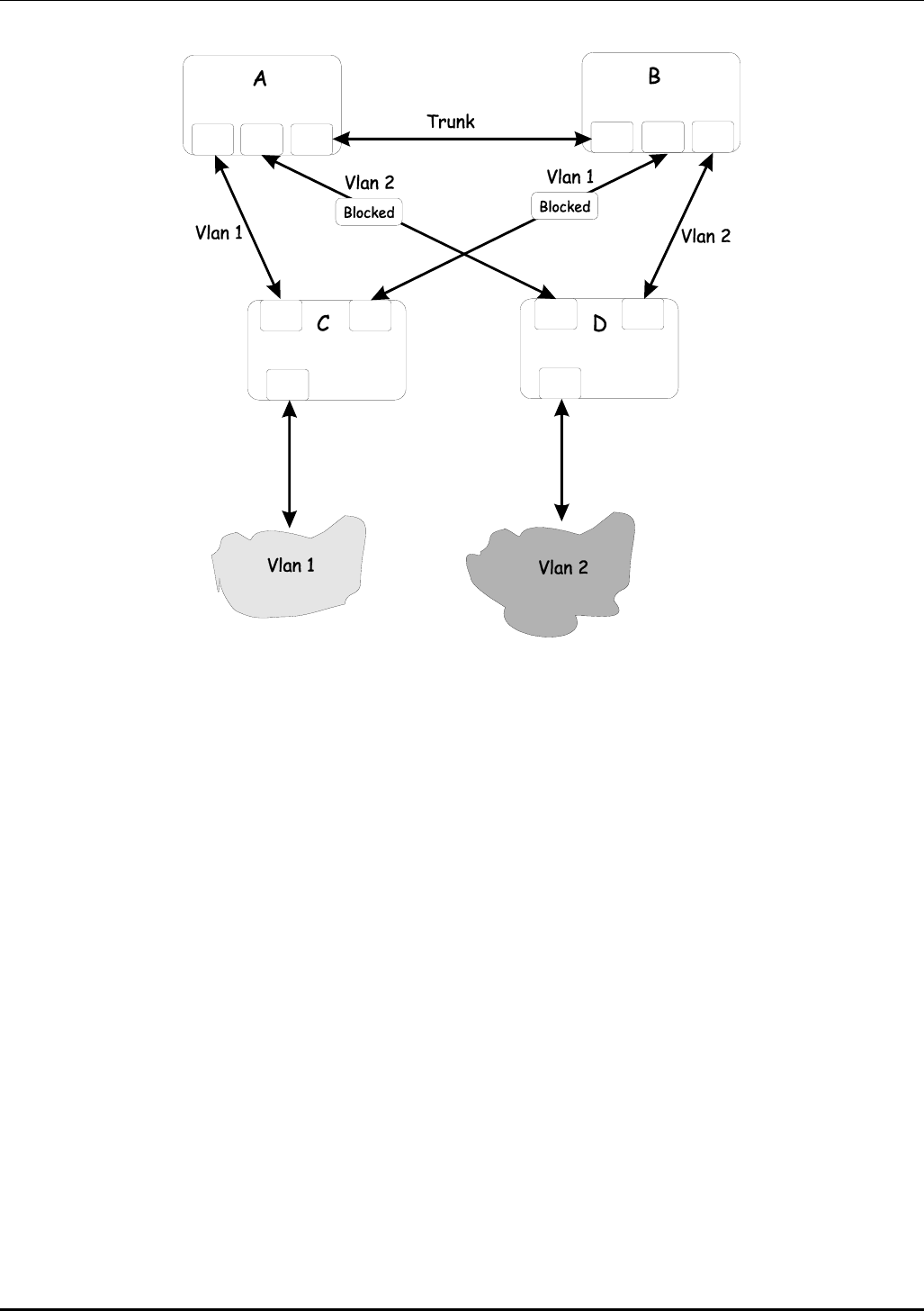
DES-3226 NWay Standalone Fast Ethernet Switch User’s Guide
In this example, the VLAN definitions are extended to switches A and B. This gives only a single blocked
port per VLAN and allows the removal of all redundant links by removing switch A or B from the
network.
162

DES-3226 NWay Standalone Fast Ethernet Switch User’s Guide
E
BRIEF REVIEW OF BITWISE LOGICAL
OPERATIONS
AND
The logical AND operation compares 2 bits and if they are both “1”, then the result is “1”,
otherwise, the result is “0”.
0 1
0 0 0
1 0 1
OR
The logical OR operation compares 2 bits and if either or both bits are “1”, then the result is “1”,
otherwise, the result is “0”.
0 1
0
0 1
1
1 1
XOR
The logical XOR (exclusive OR) operation compares 2 bits and if exactly one of them is a “1”, then
the result is “1”, otherwise the result is “0”.
0 1
0
0 1
1
1 0
NOT
The logical NOT operation simply changes the value of a single bit. If it is a “1”, the result is
“0”, if it is a “0”, the result is “1”. This operation is carried out on a single bit.
0 1
1 0
163

DES-3226 NWay Standalone Fast Ethernet Switch User’s Guide
INDEX
Dynamic filtering...................................................20
A
E
AC inputs ............................................................ 149
AC power cord........................................................ 5 Egress port .............................................................27
Access Rights End Node ...............................................................14
read only ............................................................ 83 F
read/write ........................................................... 83
Accessory pack ....................................................... 5 factory reset ...........................................................42
Administrator ........................................................ 39 Filtering..................................................................20
Aging Time, definition of ..................................... 20 Flash memory ..........................................................3
Aging Time, range of............................................ 20 Forwarding.............................................................20
Auto polarity detection............................................ 2 Front Panel...............................................................8
Automatic learning................................................ 20 Full-duplex...............................................................2
auto-negotiate.......................................................... 2 G
B gateway router .......................................................18
BOOTP protocol ................................................... 46 H
BOOTP server....................................................... 46
Bridge Forward Delay........................................... 25 half-duplex...............................................................2
Bridge Hello Time........................................... 25, 52 Humidity..............................................................149
Bridge Max. Age............................................. 25, 52 I
Bridge Priority................................................. 25, 52
broadcast domains................................................. 27 IEEE 802.1Q tagging.............................................27
IEEE 802.1Q VLANs ............................................28
C Illustration of STA.................................................25
Changing the SNMP Manager Configuration
parameters settings............................................. 83
Ingress port ......................................................27, 31
Internet Group Management Protocol (IGMP)48, 93
Changing your Password ...................................... 43 IP address.........................................................17, 83
Community Name ................................................. 18 IP Addresses and SNMP Community Names........17
Community name, definition of ............................ 83 IP Configuration ....................................................46
Community names L
Private ................................................................ 83
Public ................................................................. 83 LED Indicators.......................................................13
Connecting to the Switch log in ......................................................................43
VT100-compatible terminal............................... 37 Logging on.............................................................38
Connections M
Switch to End Node ........................................... 14
Switch to Hub or Switch.................................... 14 MAC address filtering ...........................................21
console ...................................................... 13, 37, 38 MAC Address Learning.......................................149
console port......................................................... 2, 8 Main Menu.....................................39, 40, 41, 42, 43
Console port (RS-232 DCE) ................................. 16 Management.............................................................3
Console port settings............................................. 16 Management Information Base (MIB)...................19
Create/Modify User Accounts............................... 43 Max. Age .........................................................25, 52
MIB........................................................................19
D MIB objects ...........................................................19
Data filtering ........................................................... 3 MIB-II....................................................................19
Data filtering rate .................................................... 3 MIB-II (RFC 1213)..................................................3
Data forwarding ...................................................... 2 MIBs ......................................................................19
Data forwarding rate ............................................... 2 mirror port..............................................................62
Default Gateway ................................................... 46 Multicasting .....................................................48, 93
Diagnostic port........................................................ 2
Dimensions.......................................................... 149
164

DES-3226 NWay Standalone Fast Ethernet Switch User’s Guide
N
Network Classes
Class A, B, C for Subnet Mask .......................... 46
NV-RAM .............................................................. 41
NWay ...................................................................... 2
O
Operating Temperature ....................................... 149
Out-of-Band/Console Setting menu...................... 50
P
password ............................................................... 38
Port Mirroring ....................................................... 62
Port Priority..................................................... 25, 53
ports......................................................................... 2
Power .................................................................... 13
Power Consumption............................................ 149
R
RAM ..................................................................... 41
RAM Buffer ........................................................ 149
Rear Panel ........................................................... 8, 9
refresh ................................................................... 38
RJ-45 Pin Specification....................................... 150
RMON probe ........................................................ 62
RS-232 .................................................................... 2
S
Save Changes ........................................................ 38
Saving Changes..................................................... 41
security............................................................ 18, 28
Setup ....................................................................... 5
sniffer .................................................................... 62
SNMP Community String ..................................... 83
SNMP Manager Configuration ............................. 83
SNMP Manager Configuration parameter
Status.................................................................. 83
SNMP Security (Community Names)................... 83
SNMP Trap Manager Configuration..................... 82
Spanning Tree Algorithm ........................................3
Spanning Tree Algorithm (STA) ...........................21
Spanning Tree Protocol .........................................20
Storage Temperature............................................149
Store and forward switching....................................2
subnet mask .....................................................46, 91
T
tagging .............................................................27, 28
TCP/IP Settings .....................................................46
Telnet .........................................................37, 48, 94
terminal emulator...................................................37
terminal parameters................................................37
Third-party vendors’ SNMP software ...................19
Transmission Methods.........................................149
Trap managers .......................................................18
Trap Type
Authentication Failure ........................................18
Cold Start............................................................18
Link Change Event .............................................18
New Root............................................................18
Topology Change ...............................................18
Warm Start..........................................................18
Traps ......................................................................18
U
unauthorized users .................................................38
Unpacking................................................................5
untagging .........................................................27, 28
User Accounts Management..................................44
username................................................................38
V
View/Delete User Accounts...................................44
VLAN ..............................................................20, 27
VT100-compatible terminal...................................37
W
Web-based management ........................................89
Weight .................................................................149
165

Offices
Australia D-Link Australasia
Unit 16, 390 Eastern Valley Way, Roseville, NSW 2069 Australia
TEL: 61-2-9417-7100 FAX: 61-2-9417-1077 TOLL FREE (Australia): 1800-177100
TOLL FREE (New Zealand): 0800-900900
URL: www.dlink.com.au E-MAIL: support@dlink.com.au & info@dlink.com.au
Level 1, 434 St. Kilda Road, Melbourne, Victoria 3004 Australia
TEL: 61-3-9281-3232 FAX: 61-3-9281-3229 MOBILE: 0412-660-064
Canada D-Link Canada
2180 Winston Park Drive, Oakville, Ontario, L6H 5W1 Canada
TEL: 1-905-829-5033 FAX: 1-905-829-5095 BBS: 1-965-279-8732
TOLL FREE: 1-800-354-6522 URL: www.dlink.ca
FTP: ftp.dlinknet.com E-MAIL: techsup@dlink.ca
Chile D-Link South America
Isidora Goyeechea 2934 of 702, Las Condes, Santiago, Chile, S. A.
TEL: 56-2-232-3185 FAX: 56-2-232-0923 URL: www.dlink.cl
E-MAIL: ccasassu@dlink.cl & tsilva@dlink.cl
China D-Link China
2F, Sigma Building, 49 Zhichun Road, Haidan District, 100080 Beijing, China
TEL: 86-10-88097777 FAX: 86-10-88096789 URL: www.dlink.com.cn
E-MAIL: liweii@digitalchina.com.cn
Denmark D-Link Denmark
Naverland 2, DK-2600 Glostrup, Copenhagen, Denmark
TEL: 45-43-969040 FAX:45-43-424347 URL: www.dlink.dk E-MAIL: info@dlink.dk
Egypt D-Link Middle East
7 Assem Ebn Sabet Street, Heliopolis, Cairo, Egypt
TEL: 20-2-635-6176 FAX: 20-2-635-6192 URL: www.dlink-me.com
E-MAIL: support@dlink-me.com & fateen@dlink-me.com
Finland D-Link Finland
Thlli-ja Pakkahuone Katajanokanlaituri 5, FIN– 00160 Helsinki
TEL: 358-9-622-91660 FAX: 358-9-622-91661 URL: www.dlink-fi.com
France D-Link France
Le Florilege #2, Allee de la Fresnerie, 78330 Fontenay le Fleury, France
TEL: 33-1-3023-8688 FAX: 33-1-3023-8689 URL: www.dlink-france.fr
E-MAIL: info@dlink-france.fr
Germany D-Link Central Europe/D-Link Deutschland GmbH
Schwalbacher Strasse 74, D-65760 Eschborn, Germany
TEL: 49-6196-77990 FAX: 49-6196-7799300 URL: www.dlink.de
BBS: 49-(0) 6192-971199 (analog) BBS: 49-(0) 6192-971198 (ISDN)
INFO: 00800-7250-0000 (toll free) HELP: 00800-7250-4000 (toll free)
REPAIR: 00800-7250-8000 E-MAIL: info@dlink.de
India D-Link India
Plot No.5, Kurla-Bandra Complex Rd., Off Cst Rd., Santacruz (E), Bombay, 400 098 India
TEL: 91-22-652-6696 FAX: 91-22-652-8914 URL: www.dlink-india.com
E-MAIL: service@dlink.india.com
Italy D-Link Mediterraneo Srl/D-Link Italia
Via Nino Bonnet n. 6/b, 20154, Milano, Italy
TEL: 39-02-2900-0676 FAX: 39-02-2900-1723 URL: www.dlink.it E-MAIL: info@dlink.it
Japan D-Link Japan
10F, 8-8-15 Nishi-Gotanda, Shinagawa-ku, Tokyo 141, Japan
TEL: 81-3-5434-9678 FAX: 81-3-5434-9868 URL: www.d-link.co.jp
E-MAIL: kida@d-link.co.jp
Netherlands D-Link Benelux
Fellenoord 1305611 ZB, Eindhoven, the Netherlands
TEL: 31-40-2668713 FAX: 31-40-2668666 URL: www.d-link-benelux.nl
Norway D-Link Norway
Waldemar Thranesgt. 77, 0175 Oslo, Norway
TEL: 47-22-991890 FAX: 47-22-207039
Russia D-Link Russia
Michurinski Prospekt 49, 117607 Moscow, Russia
TEL: 7-095-737-3389 & 7-095-737-3492 FAX: 7-095-737-3390 URL: www.dlink.ru
E-MAIL: vl@dlink.ru
Singapore D-Link International
1 International Business Park, #03-12 The Synergy, Singapore 609917
TEL: 65-774-6233 FAX: 65-774-6322 E-MAIL: info@dlink.com.sg
URL: www.dlink-intl.com
South Africa D-Link South Africa
102 – 106 Witchhazel Avenue, Einstein Park 2, Block B, Highveld Technopark,
Centurion, South Africa
TEL: 27 (0) 12-665-2165 FAX: 27 (0) 12-665-2186 URL: www.d-link.co.za
E-MAIL: attie@d-link.co.za
Spain D-Link Iberia
C/Sabino De Arana, 56 Bajos, 08028 Barcelona, Spain
TEL: 34 93 4090770 FAX: 34 93 4910795 URL: www.dlinkiberia.es
E-MAIL: info@dlinkiberia.es
Sweden D-Link Sweden
P. O. Box 15036, S-167 15 Bromma, Sweden
TEL: 46-(0) 8-564-61900 FAX: 46-(0) 8-564-61901 E-MAIL: info@dlink.se
URL: www.dlink.se
Taiwan D-Link Taiwan
2F, No. 119 Pao-Chung Rd, Hsin-Tien, Taipei, Taiwan
TEL: 886-2-2910-2626 FAX: 886-2-2910-1515 URL: www.dlinktw.com.tw
E-MAIL: dssqa@tsc.dlinktw.com.tw
Turkey D-Link Middle East
Deniz Bilgisayar, Buyukdere Cad. Naci Kasim Sk., No. 5 Mecidiyekoy, Istanbul, Turkey
TEL: 90-212-213-3400 FAX: 90-212-213-3420 E-MAIL: smorovati@dlink-me.com
U.A.E. D-Link Middle East
CHS Aptec (Dubai), P.O. Box 33550 Dubai U.A.E.
TEL: 971-4-366-885 FAX: 971-4-355-941 E-MAIL: Wxavier@dlink-me.com
U.K. D-Link Europe
4
th Floor, Merit House, Edgware Road, Colindale, London NW9 5AB United Kingdom
TEL: 44 (0) 20-8731-5555 FAX: 44 (0) 20-8731-5511 BBS: 44 (0) 181-235-5511
URL: www.dlink.co.uk E-MAIL: info@dlink.co.uk
U.S.A. D-Link U.S.A.
53 Discovery Drive, Irvine, CA 92618, USA
TEL: 1-949-788-0805 FAX: 1-949-753-7033 BBS: 1-949-455-1779 & 1-949-455-9616
INFO: 1-800-326-1688 URL: www.dlink.com
E-MAIL: tech@dlink.com & support@dlink.com
Registration Card
Print, type or use block letters.
Your name: Mr./Ms_____________________________________________________________________________
Organization: ________________________________________________ Dept. ____________________________
Your title at organization: ________________________________________________________________________
Telephone: _______________________________________ Fax:________________________________________
Organization's full address: ______________________________________________________________________
____________________________________________________________________________________________
Country: _____________________________________________________________________________________
Date of purchase (Month/Day/Year): _______________________________________________________________
Product Model Product Serial
No.
* Product installed in type of
computer (e.g., Compaq 486)
* Product installed in
computer serial No.
(* Applies to adapters only)
Product was purchased from:
Reseller's name: ______________________________________________________________________________
Telephone: _______________________________________ Fax:________________________________________
Reseller's full address: _________________________________________________________________________
_________________________________________________________________________
_________________________________________________________________________
Answers to the following questions help us to support your product:
1. Where and how will the product primarily be used?
Home Office Travel Company Business Home Business Personal Use
2. How many employees work at installation site?
1 employee 2-9 10-49 50-99 100-499 500-999 1000 or more
3. What network protocol(s) does your organization use ?
XNS/IPX TCP/IP DECnet Others_____________________________
4. What network operating system(s) does your organization use ?
D-Link LANsmart Novell NetWare NetWare Lite SCO Unix/Xenix PC NFS 3Com 3+Open
Banyan Vines DECnet Pathwork Windows NT Windows NTAS Windows '95
Others__________________________________________
5. What network management program does your organization use ?
D-View HP OpenView/Windows HP OpenView/Unix SunNet Manager Novell NMS
NetView 6000 Others________________________________________
6. What network medium/media does your organization use ?
Fiber-optics Thick coax Ethernet Thin coax Ethernet 10BASE-T UTP/STP
100BASE-TX 100BASE-T4 100VGAnyLAN Others_________________
7. What applications are used on your network?
Desktop publishing Spreadsheet Word processing CAD/CAM
Database management Accounting Others_____________________
8. What category best describes your company?
Aerospace Engineering Education Finance Hospital Legal Insurance/Real Estate Manufacturing
Retail/Chainstore/Wholesale Government Transportation/Utilities/Communication VAR
System house/company Other________________________________
9. Would you recommend your D-Link product to a friend?
Yes No Don't know yet
10.Your comments on this product?
_______________________________________________________________________________________