D Link DSL2640R Wireless ADSL2+ Router User Manual DSL 2640R manual 005 20070926
D Link Corporation Wireless ADSL2+ Router DSL 2640R manual 005 20070926
D Link >
Contents
- 1. Part 1
- 2. Part 2
Part 2
Section 3 – Configuration
D-Link DSL-2640R User Manual 28
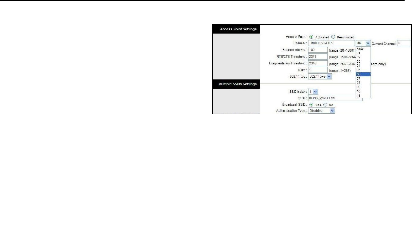
Basic Wireless
To disable the wireless interface: click in the Deactivated option next to
Access Point: and click the SAVE button. This will immediately disable
the wireless access point; it is not necessary to restart the access point to
make this change.
If the wireless interface has been disabled: click in the Activated
option next to Access Point: and click the SAVE button. This will
immediately disable the wireless access point; it is not necessary to
restart the access point to make this change.
The SSID can be changed to suit your wireless network. Remember that
any wireless device using the access point must have the same SSID and
use the same channel. The SSID can be a continuous character string
(i.e. no spaces) of up to 16 characters in length. The Channel ID: may be
changed to channels that are available in your region. Channels available
for wireless LAN communication are subject to regional and national
regulation. Click the SAVE button to save any change to the Channel.
Wireless Security
The wireless security features are used to limit access to the device or to
encrypt data and shared information. The available standardized security
for wireless LAN includes WEP and WPA Wireless security is configured
with the Wireless Settings menu located in the Home directory.
In the Wireless Settings menu, select the type of security you want to
configure. The menu will change to present the settings specific to the
method being configured. The Router’s wireless security options include
three levels of WEP encryption and WPA with a user configured Pre
Shared Key (PSK).
Configure the wireless security arrangement to suit your 802.11g
environment and click the SAVE button. The settings will go into effect
immediately. There is no need to restart the access point.
The table below provides a summary of the settings in the Wireless
Settings menu.
Note: Before enabling any security function for wireless operation,
you may want to test the Router’s access point first to verify that
wireless workstations can associate with it and use it for Internet
access.
Section 3 – Configuration
D-Link DSL-2640R User Manual 29
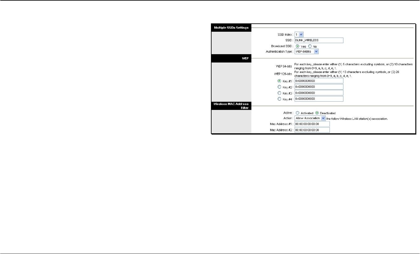
WEP Encryption
WEP (Wireless Encryption Protocol or Wired Equivalent Privacy)
encryption can be enabled for security and privacy. WEP encrypts the
data portion of each frame transmitted from the wireless adapter using
one of the predefined keys. Decryption of the data contained in each
packet can only be done if the both the receiver and transmitter have the
correct key.
By default authentication is disabled on the access point. To enable
WEP, select the WEP-64Bits or WEP-128Bits option, configure the
WEP Encryption Keys as desired and click the SAVE button. The
encryption key setup is described below.
Encryption Keys
WEP Keys may be configured using Hex or ASCII characters. There are
two levels of encryption available, each level requires a different number
of characters. Select Hex or ASCII from the Key Type drop-down menu.
Hex or Hexadecimal digits are defined as the numerical digits 0 – 9 and
the letters A – F (upper and lower case are recognized as the same
digit). ASCII characters include numbers and letters but no spaces. An
upper case ASCII character is NOT recognized as the same lower case
character, and therefore must be configured exactly as typed for all
wireless nodes using the access point. The length of the key depends
on the level of encryption used.
Select the Key Length from the drop-down menu. The available key
lengths are 64 or 128-bit encryption. In the spaces provided, type in Key
1, Key 2, Key 3 and Key 4. The length of the character string used of
the keys depends on the level (Key Length) of encryption selected.
Only one key can be active. The active key is selected by clicking the
radio button for the key you want to use.
Click the SAVE button when you have configured WEP as desired to put
the changes into effect.
Section 3 – Configuration
D-Link DSL-2640R User Manual 30
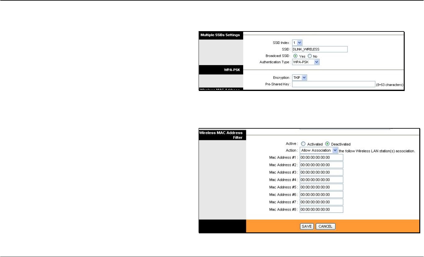
WPA Settings
WPA uses an encryption method combined with an authentication
procedure that requires an acceptance of a pre-configured
password. WPA or Wireless Protection Access is an improved
standard of wireless security. The ROUTER also supports two
common encryption types TKIP and AES.
To configure WPA settings, select the Authentication Type option
WPA-PSK to use TKIP encryption or select WPA2-PSK to use
AES encryption. The encryption algorithm TKIP (Temporal Key
Integrity Protocol) uses per packet key generation (based on
WEP), while AES (Advanced Encryption Standard) is a block-
based encryption method. Both methods require entry of a
pre-shared key to allow association. Type a password from 8 to 64
characters long in the Pre-Shared Key field.
Wireless MAC Address Filter
MAC address device filtering on the wireless LAN can be activated
and configured to allow exclusive association or deny association
with the access point.
To use MAC address filtering, click to select the Activated option
and specify the MAC addresses allowed or denied association in
the entry fields provided. Up to 8 MAC addresses can be added to
the list. Select the action to be performed on the MAC addresses in
the list. Choose Allow Association to allow association to only the
MAC address listed. This option will filter or deny association to
any device not listed. Alternatively the Deny Association option
will deny association to only the MAC addresses listed.
Click SAVE to apply and save the new filtering rules. MAC address
filtering can be Deactivated at any time, the MAC addresses in the
list remain until they are deleted by the administrator. A MAC
address on the list can be removed by highlighting it with cursor,
pressing the Delete key on your keyboard and pressing SAVE.
Section 3 – Configuration
D-Link DSL-2640R User Manual 31
Advanced Setup
The Advanced Setup folder contains windows for Routing, NAT and ADSL.
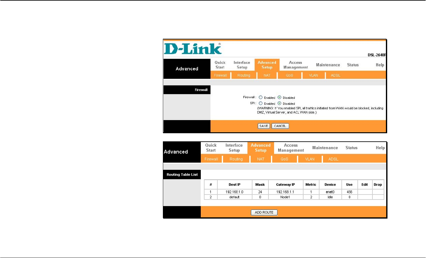
Firewall
This menu allows the Router to enforce specific
policies intended to protect the private network against
certain types of attacks.
To enable the firewall feature, select the Enabled
option and click SAVE.
To enable the Stateful Packet Inspection feature,
select the Enabled option and click SAVE.
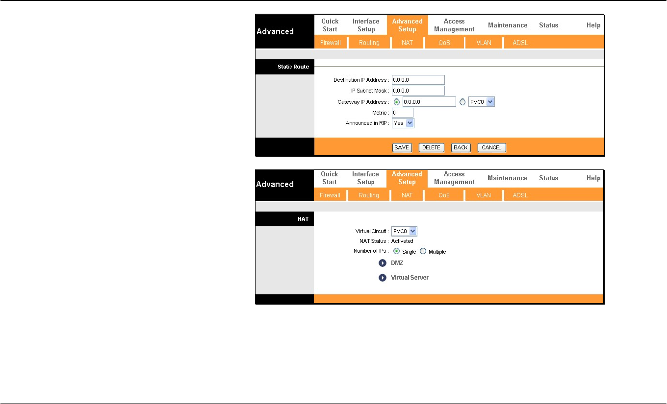
Routing
Use Static Routing to specify a route used for data
traffic within your Ethernet LAN or to route data on the
WAN. This specifies that all packets destined for a
particular network or subnet use a predetermined
gateway.
To add a static route to a specific destination IP on the
local network, click the ADD ROUTE button to view
the setup window.
Section 3 – Configuration
D-Link DSL-2640R User Manual 32
To add a static route to a specific destination IP on the
local network, enter a Destination IP Address, select
a suitable IP Subnet Mask, and type in the Gateway
IP Address. Click SAVE to enter the new static route
in the table below. The route becomes active
immediately upon creation. The Metric field
determines the number of hops or routers that will be
allowed to route traffic.
NAT
The Router features include policy-based Network
Address Translation (NAT) for greater flexiblity and
control of NAT functions. The user can customize port
mapping for a single global IP address or full feature
NAT support for mapping multiple global IP addresses
to servers or clients on the LAN. Single User
Account (SUA) NAT is enabled by default. Using the
default settings, NAT will function for Routed
connections without any additional configuration. NAT
is disabled automatically when the device is operating
in pure Bridge mode.
To customize NAT settings for IP address mapping,
use the NAT window located in the Advanced Setup
directory.
Section 3 – Configuration
D-Link DSL-2640R User Manual 33
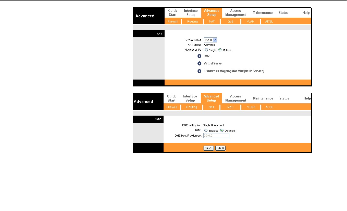
Note that if the NAT Status in the window above
indicates “Deactivated,” the user must first activate
NAT on the Internet menu. Click SAVE and the
window above will appear. The IP Address Mapping
(for Multiple IP Service) link only appears when the
Multiple option is selected under Number of IPs.
DMZ
Since some applications are not compatible with NAT,
the Router supports use of a DMZ IP address for a
single host on the LAN. This IP address is not
protected by NAT and will therefore be visible to
agents on the Internet with the right type of software.
Keep in mind that any client PC in the DMZ will be
exposed to various types of security risks. If you use
the DMZ, take measures (such as client-based virus
protection) to protect the remaining client PCs on your
LAN from possible contamination through the DMZ.
To designate a DMZ IP address, select the Enabled
radio button, type in the DMZ Host P Address of the
server or device on your LAN, and click the SAVE
button. To remove DMZ status from the designated IP
address, select the Disabled radio button and click
SAVE. It will be necessary to save the settings and
reboot the Router before the DMZ is activated.
Section 3 – Configuration
D-Link DSL-2640R User Manual 34
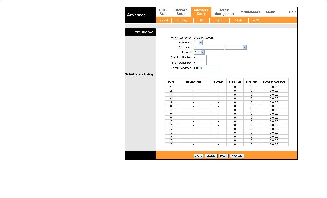
Virtual Server
To customize inbound port mapping of NAT for a
Single User Account using one global IP address,
select the Single option under Number of IPs and
click the Virtual Server link.
By default, NAT will map all ports according to the
traditional IP NAT protocol. However, the user may opt
to map specific ports or a range of ports to a specified
IP address on the LAN. It is also possible to map all
ports to a specified LAN IP address. You will use this
same window if you are using NAT for a multiple
number of IPs.
To specify NAT mapping, type in the port or range of
ports used for mapping in the Start Port Number and
End Port Number columns and enter the LAN Local
IP Address of the server or system used for the
selected ports. To map a single port, type the port
number in both Start and End port entry fields. Click
the SAVE button to apply the NAT port mapping and
save the settings.
Section 3 – Configuration
D-Link DSL-2640R User Manual 35
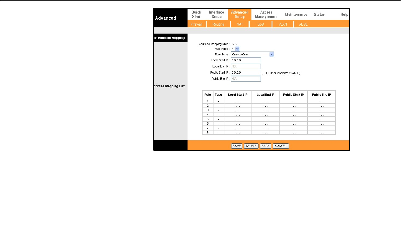
IP Address Mapping
The Router allows the user to setup policies used for
inbound or outbound port mapping to one or multiple
global IP addresses. This may be desirable on
networks that maintain multiple global IP addresses,
multiple virtual connections or where servers on the
network must respond to connection requests from the
WAN.
To configure the mapping rules, select the select the
Multiple option under Number of IPs on the NAT
menu and click the IP Address Mapping (for
Multiple IP Service) link.
To edit a rule, use the Rule Index drop-down menu.
One you have made the desired changes, click the
SAVE button.
Rule Types:
One-to-One
Many-to-One
Many-to-Many No Overload
Use this for mapping a single global IP address to a single private internal IP address. In this
case, IP mapping is done for both inbound and outbound traffic.
This is essentially the same as SUA NAT. Multiple private internal IP addresses are mapped to
a single global IP address. Mapping occurs for outbound traffic.
Many-to-Many Overload In this case, IP mapping is done for outbound traffic from multiple
private internal IP addresses to a shared pool of multiple global IP addresses.
IP mapping is also done for outbound traffic from multiple private internal IP addresses to a
pool of global IP addresses, however each internal IP address will connect to a single global IP
address from the pool. In other words each available global IP address is allowed connection to
only one internal IP address at a time.
Section 3 – Configuration
D-Link DSL-2640R User Manual 36
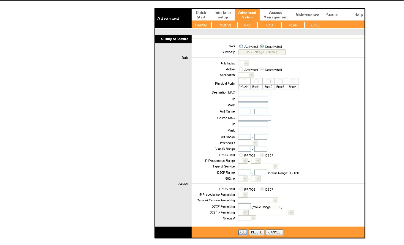
QoS
Quality of Service or QoS assigns a priority level to
data packets to make sure time sensitive network
applications operate smoothly with minimal delay.
QoS enables applications such as VoIP (voice-over
Internet Protocol) or video conferencing to function
well on networks that may have multiple simultaneous
transmissions of many types of data. Since much of
the traffic is not significantly affected by slight
transmission delay, QoS is used to give preference to
traffic that is affected by delay.
QoS implementation on the Router instead uses four
queues that can be mapped to and assigned priority.
QoS protocols supported on the Router include IEEE
802.1p, Differentiated Services Code Point (DiffServ)
weighted scheduling, IP Type of Service (IP ToS) as
well as application specific and VLAN Group QoS
mapping. To implement QoS on the Router, select the
preferred protocol used for QoS and map the priority
scheduling used to the four queues used on the
Router.
To enable QoS, select the QoS: Activated option, and
select the type of QoS mapping used. Use Queue #1
for the lowest priority traffic, and Queue #4 for the
highest priority traffic.

Section 3 – Configuration
D-Link DSL-2640R User Manual 37
802.1p To implement QoS mapping for IEEE 802.1p priority, select the Activated option and configure mapping for the 8 priority levels
defined by 802.1p priority. 802.1p user priority 0 is the lowest priority while 7 is the highest.
IP QoS To implement QoS mapping for IP QoS, select the Activated option and configure mapping for one of two types of IP QoS, IP
ToS (Type of Service) or DiffServ:
IP ToS assigns 0 for the lowest priority and 7 for the highest.
DiffServ uses 64 levels with 0 being the lowest, 63 the highest. DiffServ QoS mapping requires mapping for all 64 levels.
If a level is not mapped a popup box informs the user that the level has not been assigned.
Application QoS To implement Application QoS mapping, select the Activated option and configure queue assignment for applications. The
default applications mapping for voice and video applications set the highest priority for voice and second highest for video. The
queue assignment and RTP port ranges may be changed if desired. Queues may also be assigned for IGMP packets and
general data packets (i.e. all other traffic).
VLAN Group
QoS To implement VLAN Group QoS mapping, select the Activated option and configure mapping for VLAN groups using the VLAN
group identification number (VID) for queue mapping. This can be used together with VLAN assignment for different virtual
connections (PVCs) for QoS mapping to the PVCs. See below for more information on how VLANs can be used on the Router.
Section 3 – Configuration
D-Link DSL-2640R User Manual 38
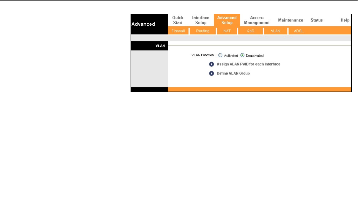
VLAN
The Router supports port-based VLANs to segment
the Ethernet LAN and/or map 802.1Q VLAN groups
to different PVCs.
VLANs are grouped according to physical Ethernet
port or by PVC for users running multiple
connections on the WAN. To use VLANs select the
Activated option, then open a separate menu to
Assign VLAN PVID for Each Interface. When
multiple connections are used on the WAN, this is
especially useful to assign VLAN user groups to
specified PVCs.
The Define VLAN Group menu is used to set up
VLAN user groups and implement VLAN taqging.
Section 3 – Configuration
D-Link DSL-2640R User Manual 39
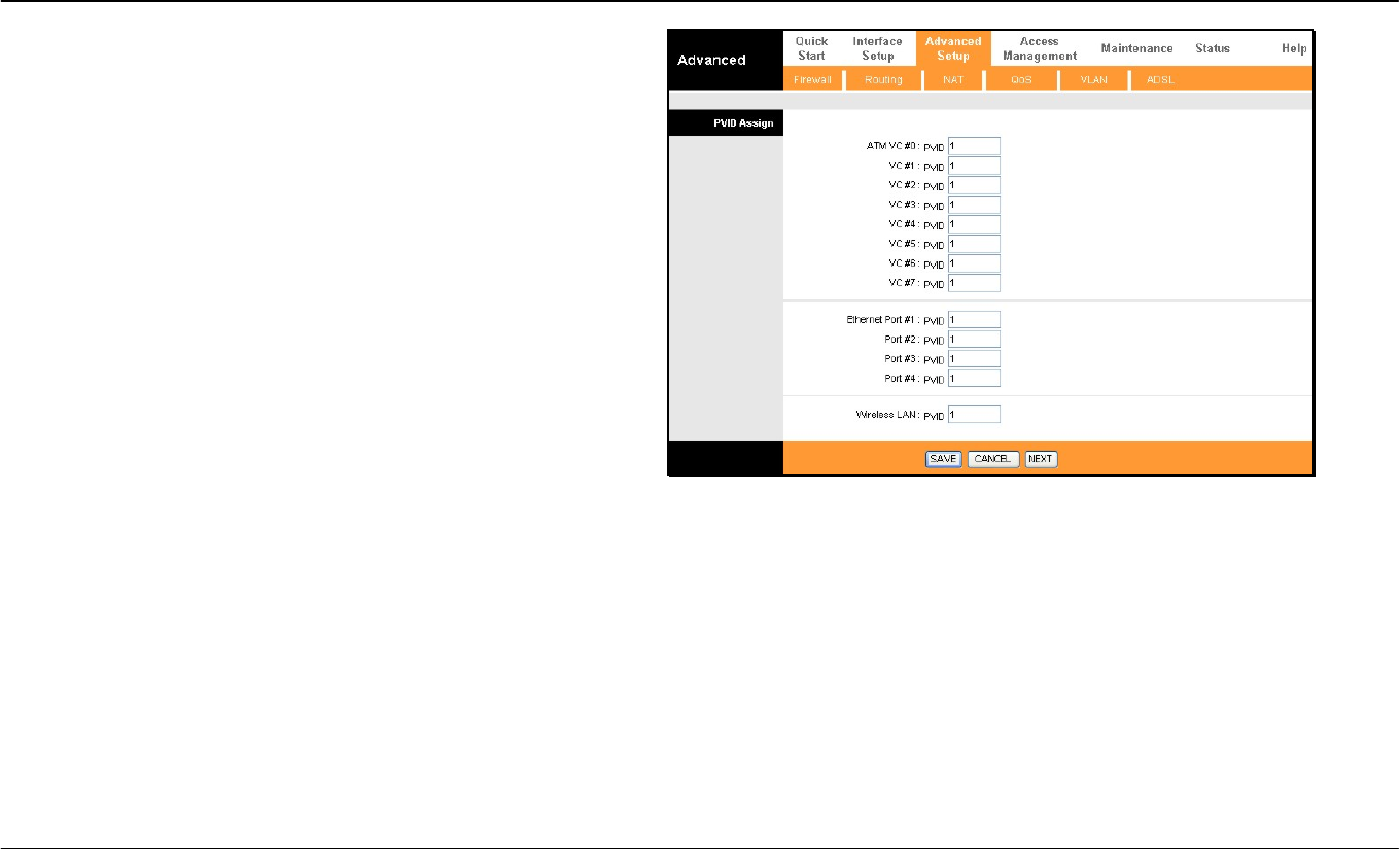
Assign PVID
Enter the desired PVID values in the menu and then click the SAVE
button. PVIDs assignment can be used to create port-based VLANs
for any of the four Ethernet ports; or use the PVID to map VLANs to
separate PVCs. The eight PVCs are labeled ATM VC # 1, VC # 2
and so on up to VC # 7 for the purpose of VLAN to PVC mapping.
Section 3 – Configuration
D-Link DSL-2640R User Manual 40
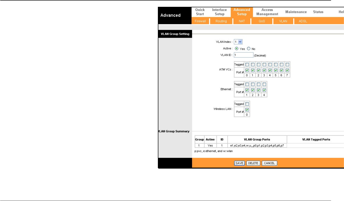
VLAN
To define a VLAN group, click Define VLAN Group in the VLAN
menu to access the VLAN Group Setting menu.
Make the desired VLAN Group assignment and tagging settings in
the window above and then click the SAVE button.
Up to eight VLAN groups may be created. Click to select the
Ethernet Port and ATM VCs Port for each VLAN member port. Any
port may be specified as Tagged.
Packets that are tagged (are carrying the 802.1Q VID information)
can be transmitted from one 802.1Q compliant network device to
another with the VLAN information intact. This allows 802.1Q VLANs
to span network devices (and indeed, the entire network, if all
network devices are 802.1Q compliant).
Select the Tagged option to enable tagging for the port. Ports with
tagging enabled will put the VID number, priority and other VLAN
information into the header of all packets that flow into and out of it. If
a packet has previously been tagged, the port will not alter the
packet, thus keeping the VLAN information intact. Other 802.1Q
compliant devices on the network to make packet-forwarding
decisions can then use the VLAN information in the tag.
Section 3 – Configuration
D-Link DSL-2640R User Manual 41
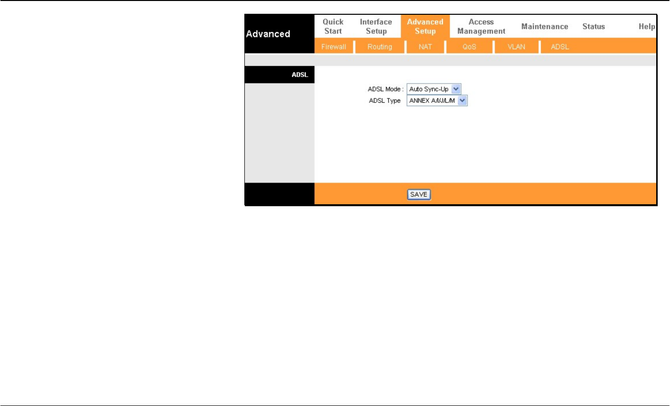
ADSL
This menu allows the user to set the configuration
for ADSL protocols. For most ADSL accounts the
default settings will work. This configuration works
with all ADSL implementations. If you have been
given instructions to change the ADSL Mode or
ADSL Type, select the desired option from the
drop-down menus and click the SAVE button.
Section 3 – Configuration
D-Link DSL-2640R User Manual 42
Access Management
The Access Management directory contains links for the ACL, Filter, SNMP, UPnP, and DDNS menus.
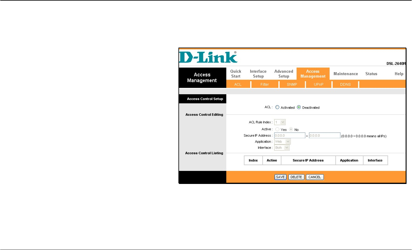
ACL
Access Control on the Router is an IP-based and/or
application-based filtering mechanism used for security and
efficiency.
Add rules to the list that specify IP address or IP address
range. For each rule, a network application can be specified.
The Interface effected can be specific to the LAN, WAN or
Both.
Click the SAVE button to apply and save the new rule. Each
rule must be indexed and can be Active or not while
remaining on the list. The entire Access Control List can be
Activated or Deactivated without change the list.
Section 3 – Configuration
D-Link DSL-2640R User Manual 43
Filter Menus
The filtering functions on the Router are based on IP address, MAC
address, URL or common network applications. Choose the type of
filtering to configure and enter the criteria appropriate for that type of
filtering. Each menu presents settings specific to the type. IP and MAC
based filtering rules can be applied sequentially so that each rule has
the option of forwarding packets that do not match the rule, or going to
the next rule on the list for further scrutiny.
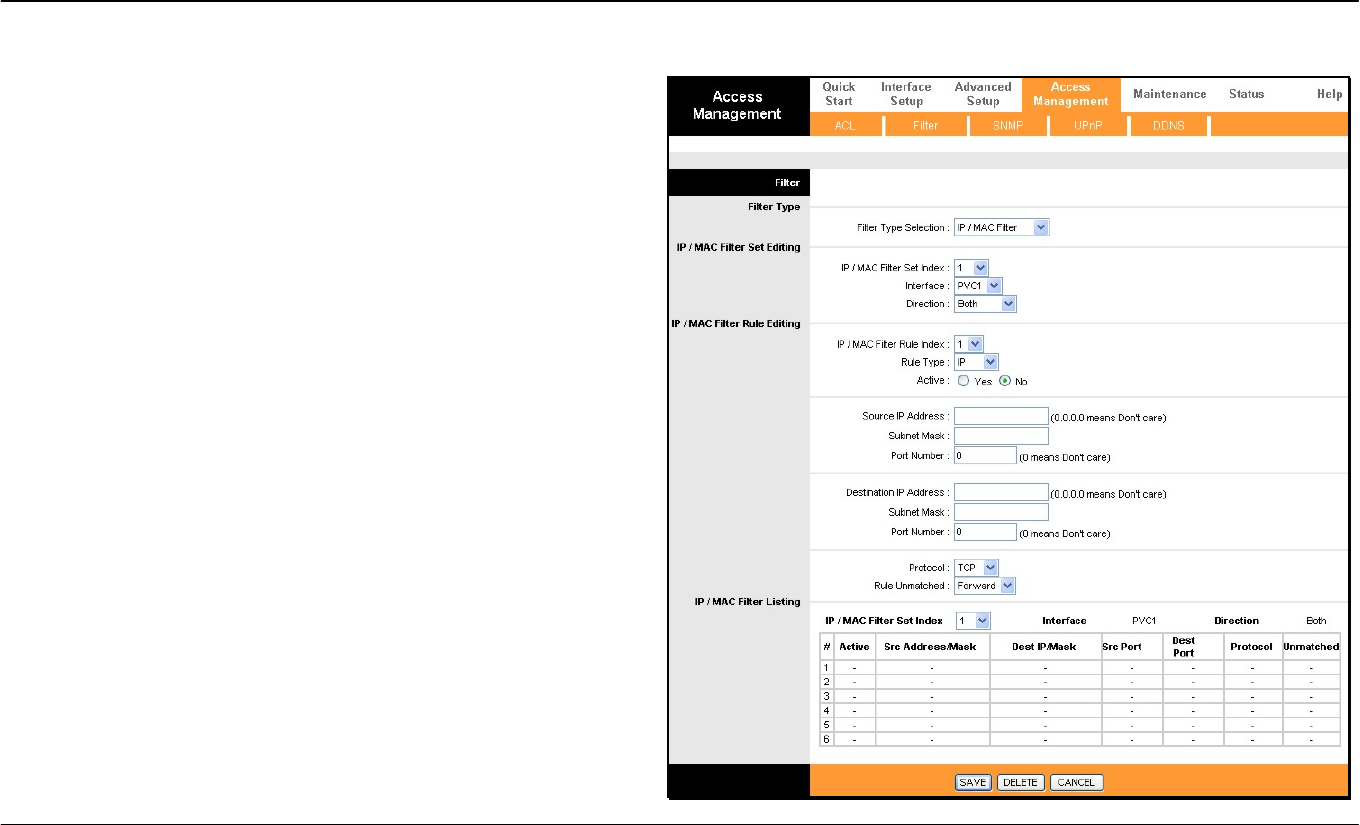
IP/MAC Based Filter
IP and MAC based filters are indexed by rule set and again by
individual rule in the set. Choose IP or MAC based filtering options and
click the SAVE button to add the new rule to the list. To remove a rule
set from the list, select it and click on the Delete button. The Rule
Unmatched option determines whether to Forward a packet or go to
Next rule on the list. Each set applies the rules in the set sequentially
in the order they are listed (or indexed).
Section 3 – Configuration
D-Link DSL-2640R User Manual 44
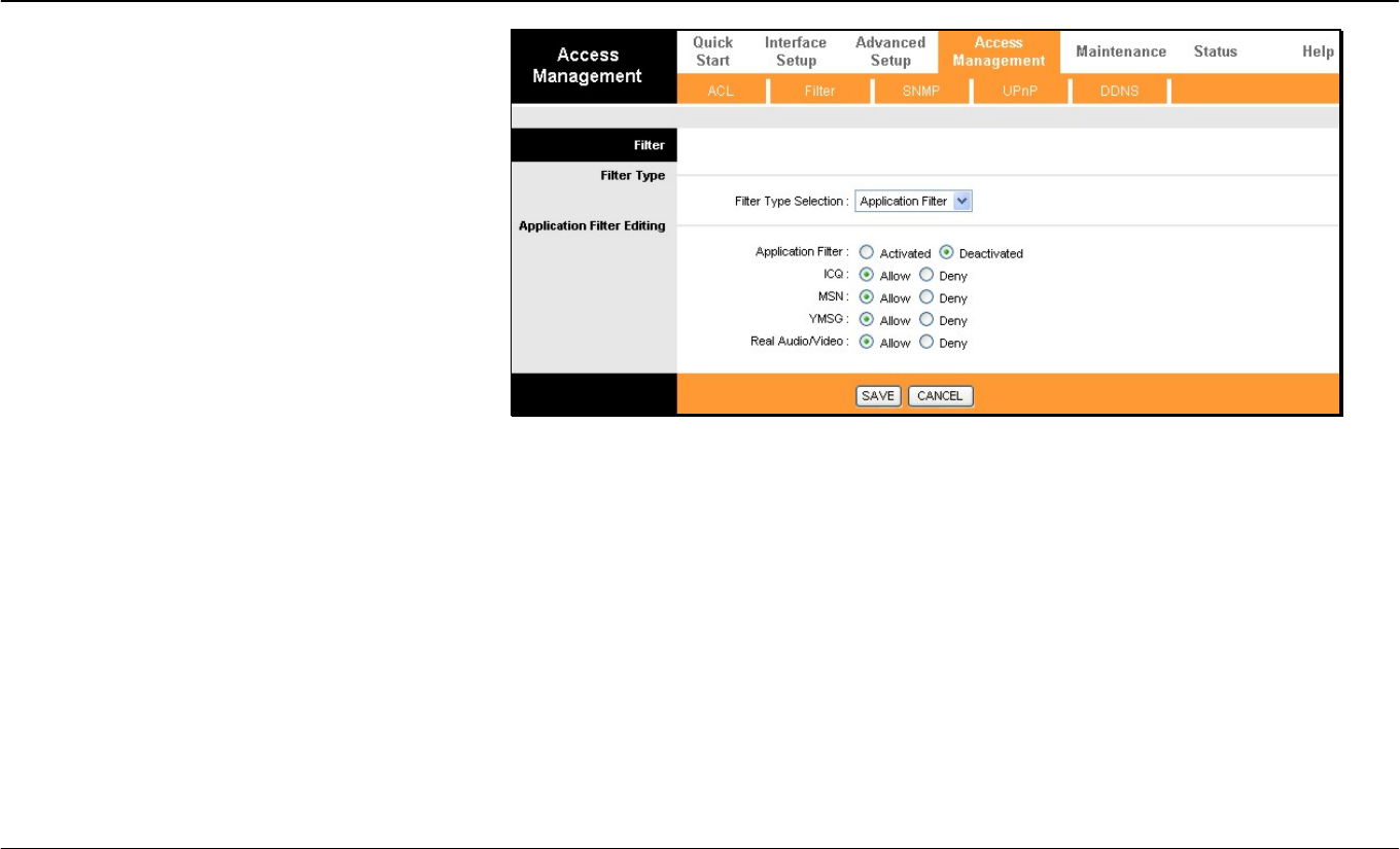
Application Filter
The Application Filter is a simple filter that drops all
incoming packets for the selected applications from
the Internet.
Choose the applications to Allow or Deny from
those listed and click the SAVE button to apply and
save the application filtering rule. The application
filter can be Activated or Deactivated at any time
without changing the selected options.
Section 3 – Configuration
D-Link DSL-2640R User Manual 45
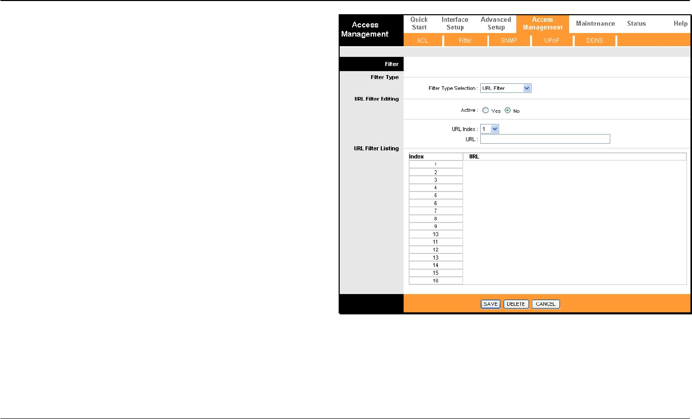
The URL Filter will deny access to any URL entered in the list. Up to
16 URLs can be specified. The URL Filter can be Active or not without
changing the entries on the list.
Select an index number for a new URL to be added to the list, type the
URL and click the SAVE button to add it to the list. Remove a URL
from the list by choosing the index number for the URL to be removed
and clicking on the Delete button.
Section 3 – Configuration
D-Link DSL-2640R User Manual 46
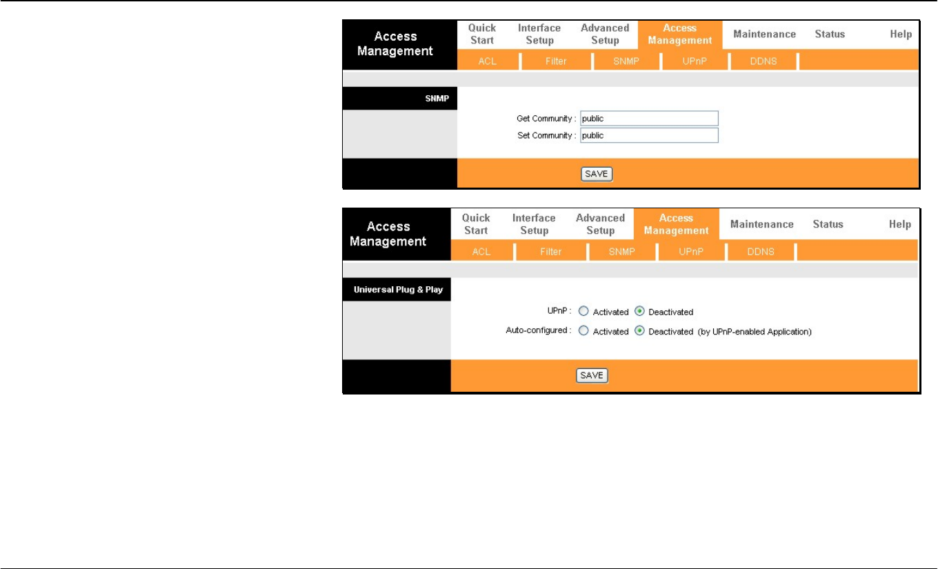
SNMP
Simple Network Management Protocol is a
standard for internetwork and intranetwork
management.
Enter the desired information in the Get
Community and Set Community fields and then
click the SAVE button when you are finished with
your SNMP settings.
UPnP
UPnP supports zero-configuration networking and
automatic discovery for many types of networked
devices. When enabled, it allows other devices that
support UPnP to dynamically join a network, obtain
an IP address, convey its capabilities, and learn
about the presence and capabilities of other
devices. DHCP and DNS service can also be used
if available on the network. UPnP also allows
supported devices to leave a network automatically
without adverse effects to the device or other
devices on the network.
Diverse networking media including Ethernet,
Firewire, phone line, and power line networking can
support UPnP.
To enable UPnP for any available connection, click
Activated, and click the SAVE button. You can also
opt to allow user to make configuration changes
through UPnP by selecting Activated under the
Auto-configured setting.
Section 3 – Configuration
D-Link DSL-2640R User Manual 47
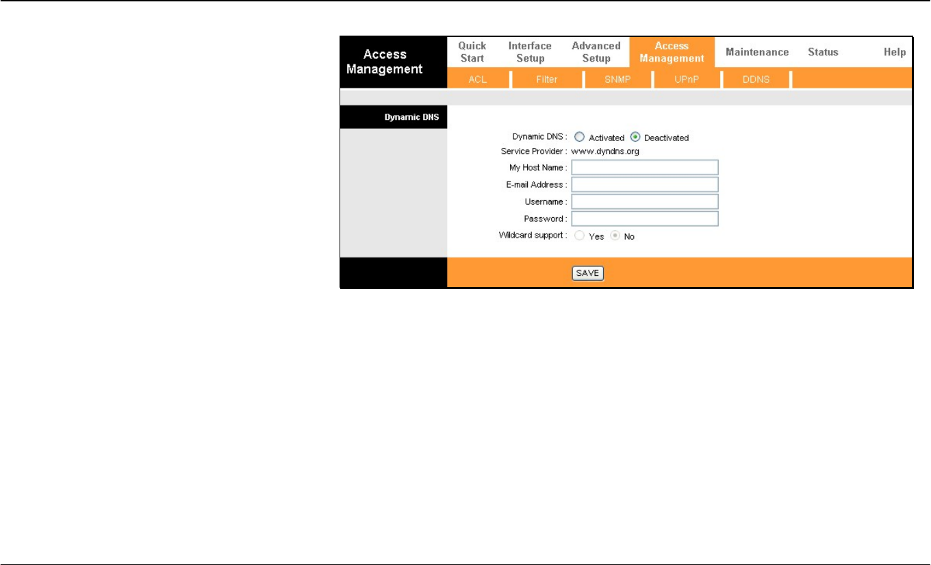
DDNS
The Router supports Dynamic Domain Name
Service or Dynamic DNS. Dynamic DNS is used for
account that may not have a permanent fixed global
IP address for servers or other resources that are
accessed through the Internet. It allows the user to
alias a dynamic IP address to a fixed host name.
To configure Dynamic DNS:
1. Click the Activated box to select it.
2. Enter the full host and domain name used for
your Dynamic DNS under My Host Name.
3. This is used to redirect e-mails arriving at
your Dynamic DNS service provider’s
address to an alternative e-mail account.
Type in the E-Mail Address that will receive
the forwarded e-mails.
4. Type in the Username for your Dynamic
DNS account.
5. Type in the Password for your Dynamic
DNS account.
6. The Wildcard support option may be
selected to allow for variations on your public
URL address to be used, for example if
upper case letters are typed in the URL.
7. Click the SAVE button to activate the
Dynamic DNS settings.
Section 3 – Configuration
D-Link DSL-2640R User Manual 48
Maintentance
The Maintenance folder contains windows for Administration, Time Zone, Firmware, SysRestart, and Diagnostics.
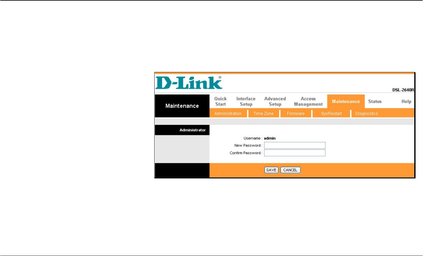
Password
Administration
To create a new password, type the new password
in the New Password field and then retype it in the
Confirm Password field.
The Username (admin) used to access the Router’s
management software cannot be changed by the
user.
Section 3 – Configuration
D-Link DSL-2640R User Manual 49
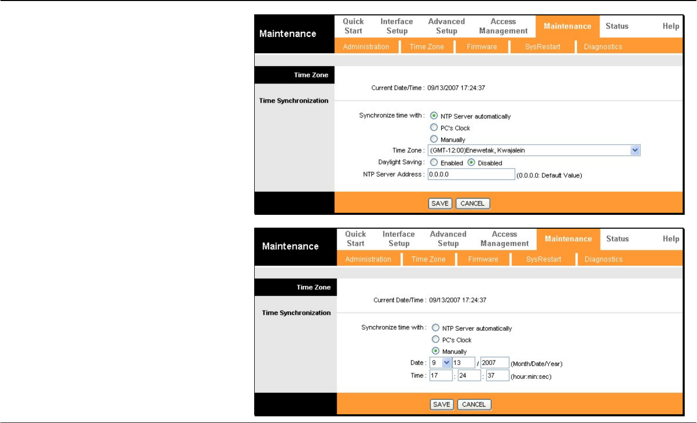
Time Zone
The Router provides a number of options to
maintain current date and time.
To configure system time on the Router, select the
method used to maintain time. If you wish to use a
network timeserver, select the method used from
the Synchronize time with radio buttons and type
in the IP address of the NTP Server Address.
Select Time Zone and choose Daylight Saving
settings where appropriate.
Alternatively, you can manually configure the
system time by clicking Manually in the
Synchronize time with section and then type in
the Date and Time in the spaces provided. Click the
SAVE button to set the system time.
Section 3 – Configuration
D-Link DSL-2640R User Manual 50
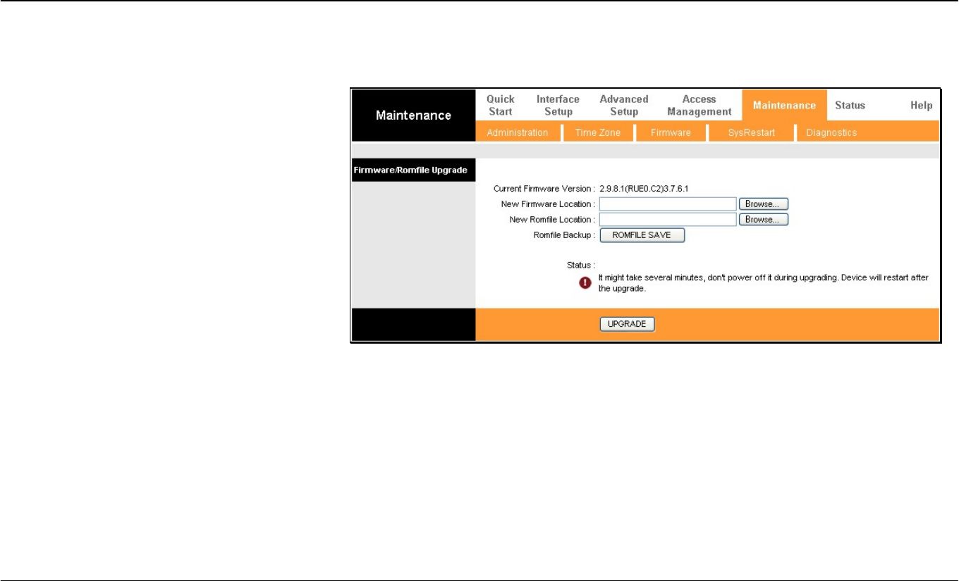
Firmware Update
Firmware
Use this window to load the latest firmware for the
device.
To upgrade firmware, type in the name and path of
the file or click on the Browse button to search for
the file. Click the UPGRADE button to begin
copying the file. The file will load and restart the
Router automatically.
Section 3 – Configuration
D-Link DSL-2640R User Manual 51
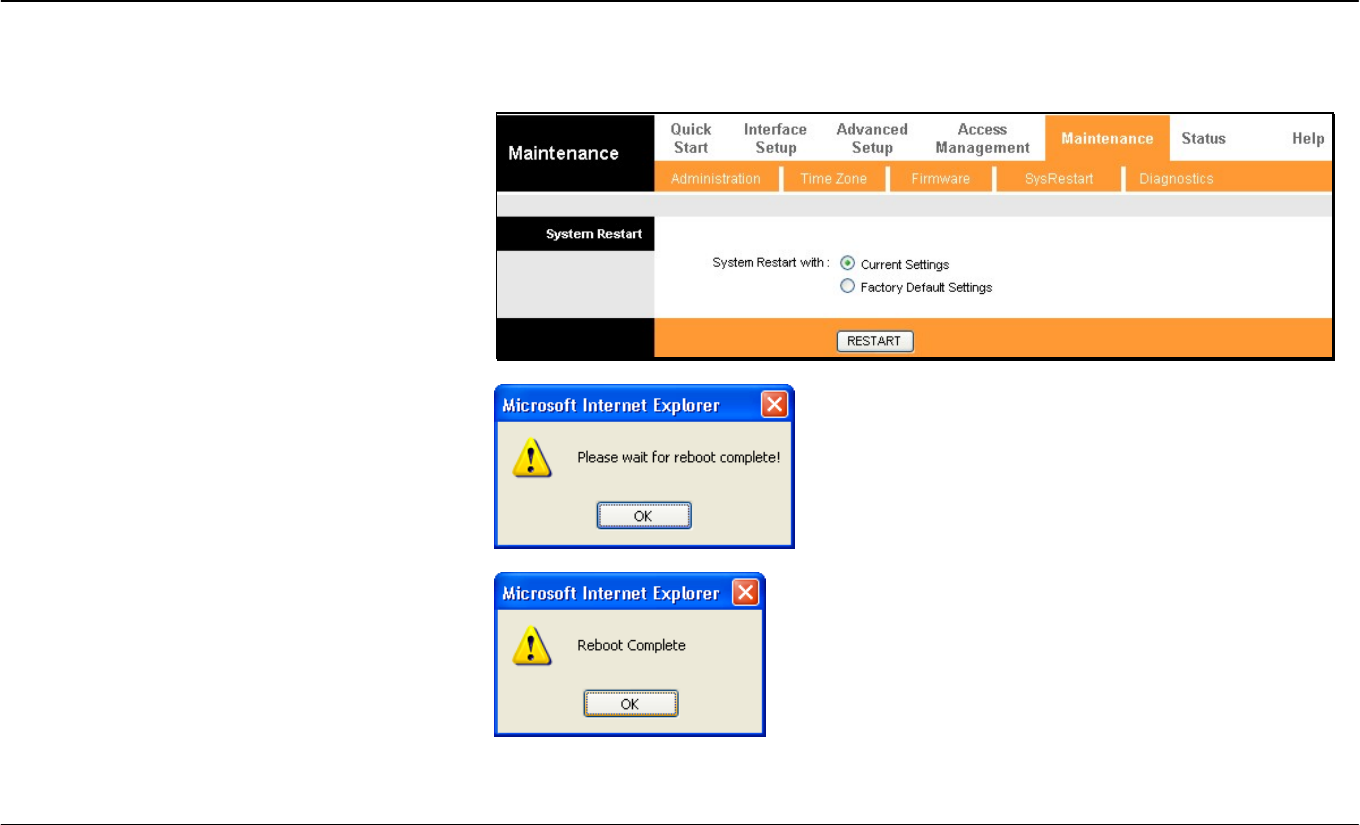
Reset/Restart System
SysRestart
To reset the Router to its factory default settings,
click the SysRestart button in the Maintenance
menu. Select the Factory Default Settings radio
button under System Restart with and click
RESTART.
To perform a simple reboot, select System Restart
with Current Settings and click RESTART.
You will be prompted to wait for the reboot to
complete.
Click OK to proceed. The Router will reset with the
factory default settings including IP settings and
administrator password. When it is finished, the
following prompt will appear:
Section 3 – Configuration
D-Link DSL-2640R User Manual 52
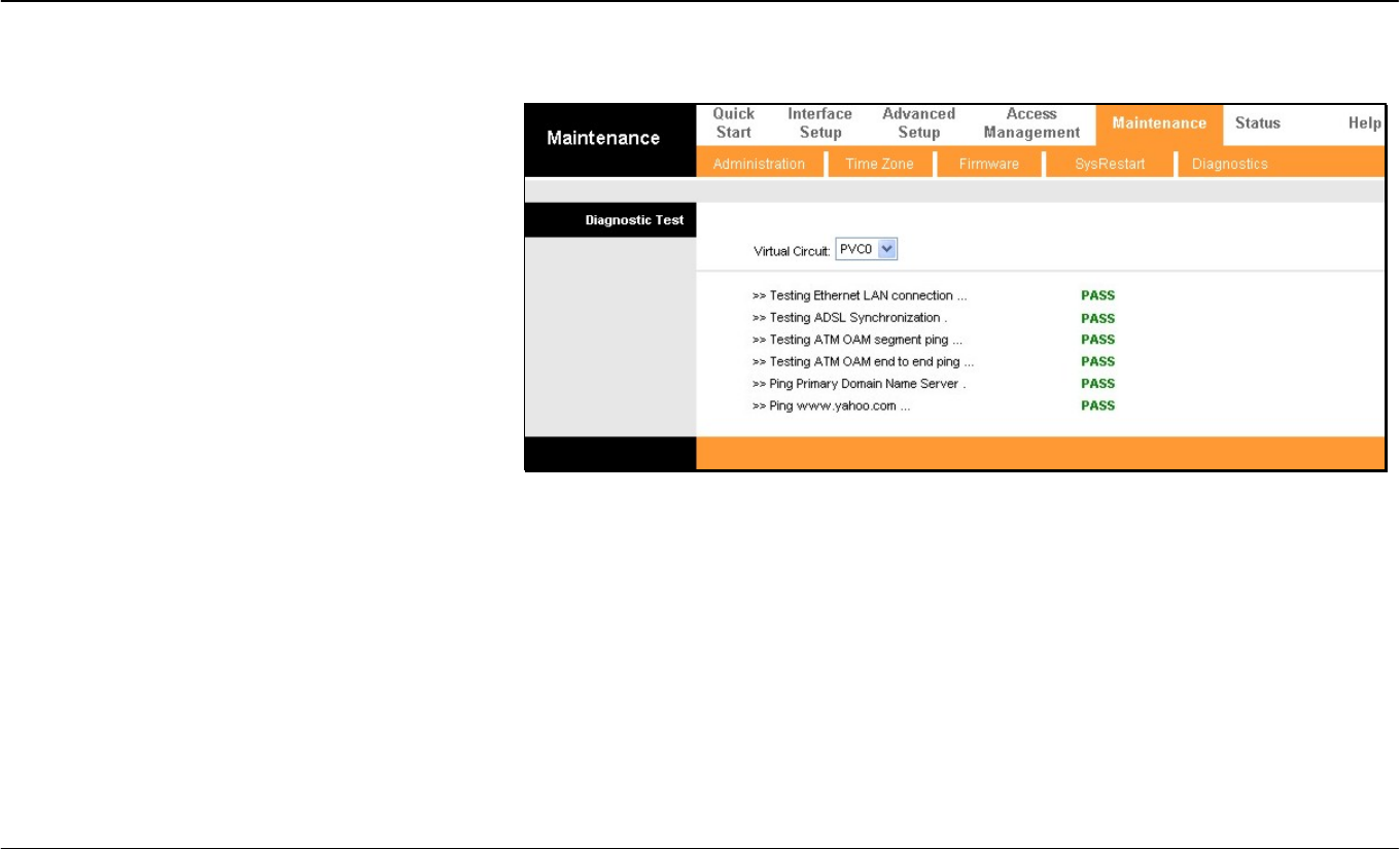
Diagnostics
Diagnostics
This window is used to test connectivity of the
Router. The diagnostic features execute a series of
tests of your system software and hardware
connections. Use these when working with your ISP
to troubleshoot problems.
Section 3 – Configuration
D-Link DSL-2640R User Manual 53
Status
The Status directory contains Device Info, System Log, and Statistics displays.
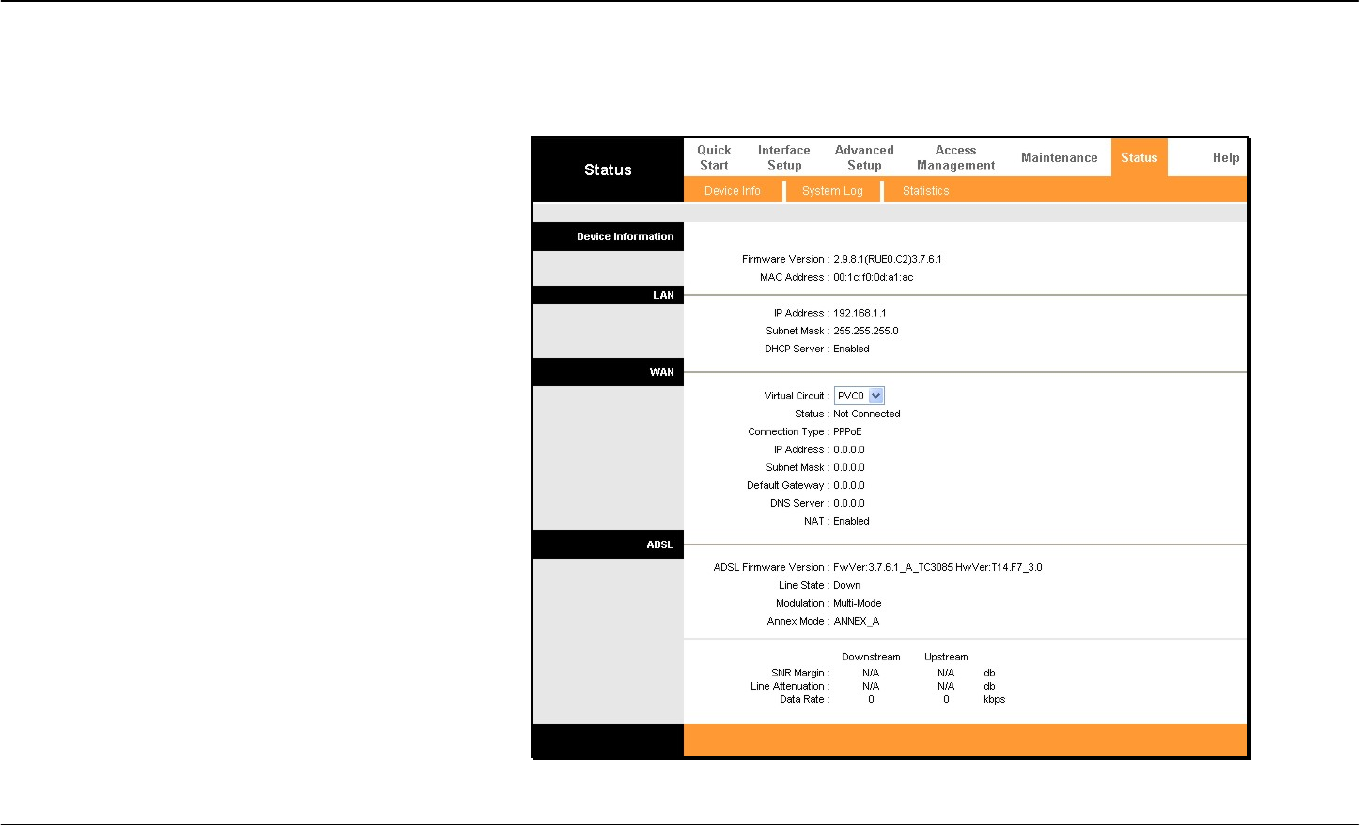
Device Info
This display window is used to view Device,
LAN, WAN, and ADSL information.
Section 3 – Configuration
D-Link DSL-2640R User Manual 54
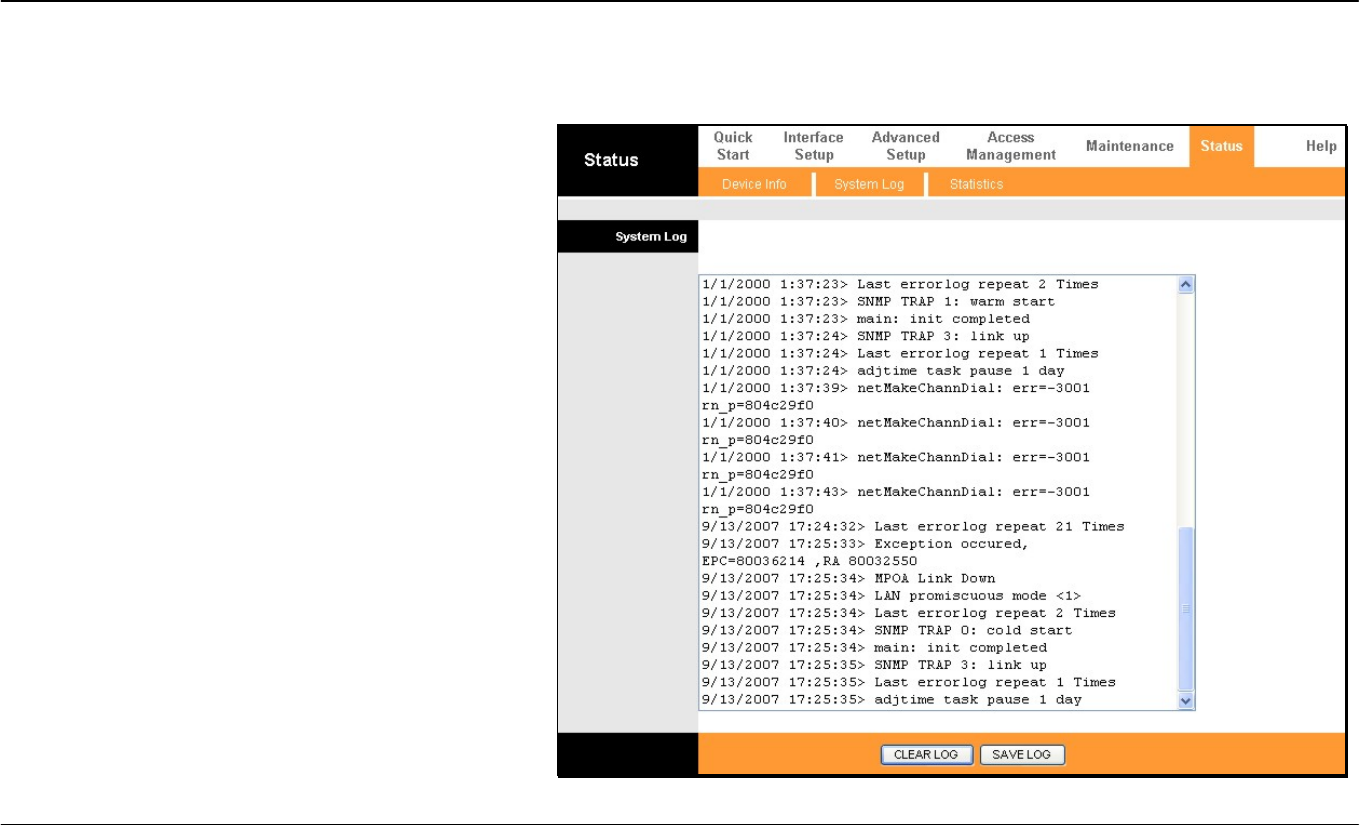
System Log
This window displays chronological event log data. Use
the navigation buttons to view or scroll log pages.
You may also save a simple text file containing the log to
your computer. Click the SAVE LOG button and follow the
prompts to save the file.
Section 3 – Configuration
D-Link DSL-2640R User Manual 55
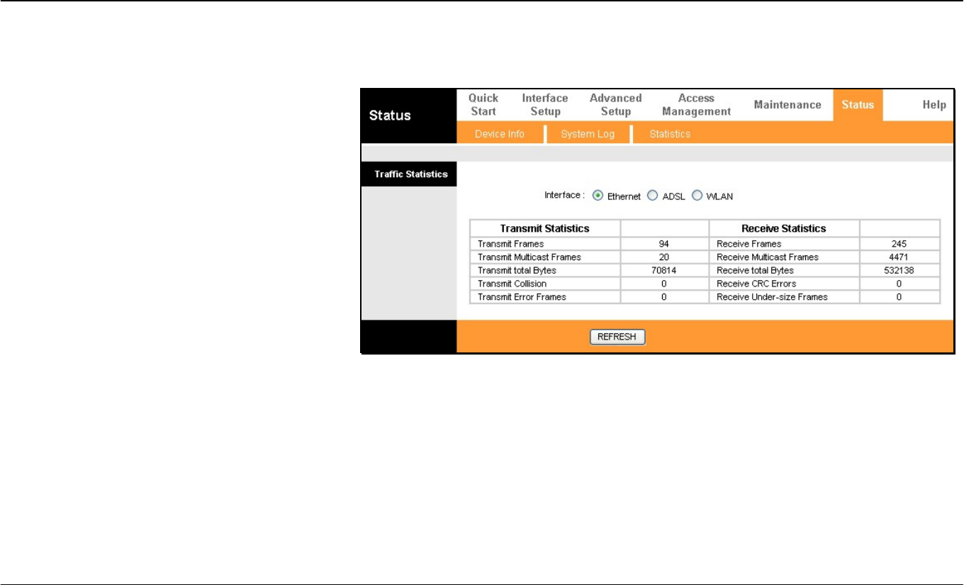
Statistics
Use the Traffic Statistics window to monitor traffic
on the Ethernet, Wireless or ADSL connection.
Select the interface for which you want to view
packet statistics and the information will appear
below.

Appendix A – Troubleshooting
D-Link DSL-2640R User Manual 56
Troubleshooting
This chapter provides solutions to problems that might occur during the installation and operation of the DSL-2640R. Read the following
descriptions if you are having problems. (The examples below are illustrated in Windows® XP. If you have a different operating system, the
screenshots on your computer will look similar to the following examples.)
1. How do I configure my DSL-2640R Router without the CD-ROM?
• Connect your PC to the Router using an Ethernet cable.
• Open a web browser and enter the address http://192.168.1.1
• The default username is ‘admin’ and the default password is ‘1234’.
• If you have changed the password and cannot remember it, you will need to reset the Router to the factory default setting (see question 2),
which will set the password back to ‘1234’.
Note: Please refer to the next section “Networking Basics” to check your PC’s IP configuration if you can’t see the login windows.
2. How do I reset my Router to the factory default settings?
• Ensure the Router is powered on.
• Press and hold the reset button on the back of the device for approximately 5 to 8 seconds.
• This process should take around 1 to 2 minutes.
Note: Resetting the Router to the factory default settings will erase the current configuration settings. To reconfigure your settings, login to the Router as
outlined in question 1, then run the Quick Setup wizard.
格式化: 項目符號及編號
格式化: 項目符號及編號

Appendix A – Troubleshooting
D-Link DSL-2640R User Manual 57
3. What can I do if my Router is not working correctly?
There are a few quick steps you can take to try and resolve any issues:
• Follow the directions in Question 2 to reset the Router.
• Check that all the cables are firmly connected at both ends.
• Check the LEDs on the front of the Router. The Power indicator should be on, the Status indicator should flash, and the DSL and LAN
indicators should be on as well.
• Please ensure that the settings in the Web-based configuration manager, e.g. ISP username and password, are the same as the settings
that have been provided by your ISP.
4. Why can’t I get an Internet connection?
For ADSL ISP users, please contact your ISP to make sure the service has been enabled/connected by your ISP and that your ISP username and
password are correct.
Appendix B - Networking Basics
D-Link DSL-2640R User Manual 58
Networking Basics
Check Your IP Address
After you install your new D-Link adapter, by default, the TCP/IP settings should be set to obtain an IP address from a DHCP server (i.e. wireless
router) automatically. To verify your IP address, please follow the steps below.
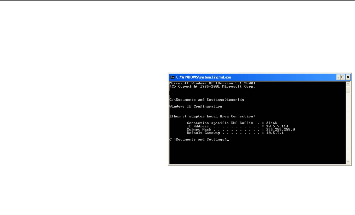
Click on Start > Run. In the run box type cmd and click on the OK.
At the prompt, type ipconfig and press Enter.
This will display the IP address, subnet mask, and the default
gateway of your adapter.
If the address is 0.0.0.0, check your adapter installation, security
settings, and the settings on your router. Some firewall software
programs may block a DHCP request on newly installed adapters.
If you are connecting to a wireless network at a hotspot (e.g. hotel,
coffee shop, airport), please contact an employee or administrator
to verify their wireless network settings.
Appendix B - Networking Basics
D-Link DSL-2640R User Manual 59
Statically Assign An IP Address
If you are not using a DHCP capable gateway/router, or you need to assign a static IP address, please follow the steps below:
Step 1
Windows® XP - Click on Start > Control Panel > Network Connections.
Windows® 2000 - From the desktop, right-click on the My Network Places > Properties.
Step 2
Right-click on the Local Area Connection which represents your D-Link network adapter and select Properties.
Step 3
Highlight Internet Protocol (TCP/IP) and click on the Properties.
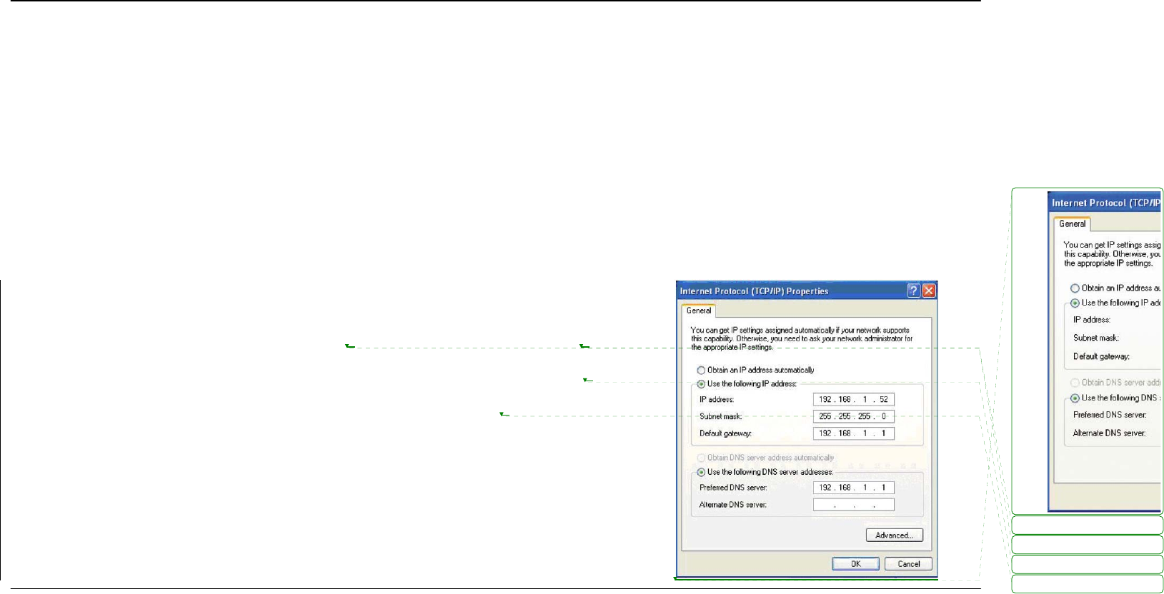
Step 4
Click on the Use the following IP address and enter an IP address that is on the same subnet as
your network or the LAN IP address on your router.
Example: If the router’s LAN IP address is 192.168.1.1, make your IP address 192.168.1.X where X
is a number between 2 and 254. Make sure that the number you choose is not in use on the
network. Set Default Gateway the same as the LAN IP address of your router (192.168.1.1).
Set Primary DNS the same as the LAN IP address of your router (192.168.1.1). The Secondary
DNS is not needed or you may enter a DNS server from your ISP.
Step 5
Click on the OK twice to save your settings.
刪除
:
刪除: 0
刪除: 0
刪除: 0
刪除: 0
Technical Specifications
ADSL Standards
• Full-rate ANSI T1.413 Issue 2
• ITU G.992.1 (G.dmt)
• ITU G.992.2 (G.lite)
• ITU G.994.1 (G.hs)
ADSL2 Standards
• ITU G.992.3 (G.dmt.bis)
ADSL2+ Standards
• ITU G.992.5 (G.dmt.bisplus)
Protocols
• IEEE 802.1d Spanning
Tree
• TCP/UDP
• ARP
• RARP
• ICMP
• RFC1058 RIP v1
• RFC1213 SNMP v1 &
v2c
• RFC1334 PAP
• RFC1389 RIP v2
• RFC1577 Classical IP
over ATM
• RFC1483/2684
Multiprotocol
Encapsulation over ATM
Adaptation Layer 5
(AAL5)
• RFC1661 Point to Point
Protocol
• RFC1994 CHAP
• RFC2131 DHCP Client /
DHCP Server
• RFC2364 PPP over ATM
• RFC2516 PPP over
Ethernet
Data Transfer Rate
• G.dmt full rate downstream: up to 8 Mbps / upstream: up to 1 Mbps
• G.lite: ADSL downstream up to 1.5 Mbps / upstream up to 512 Kbps
• G.dmt.bis full rate downstream: up to 12 Mbps / upstream: up to 12
Mbps
• ADSL full rate downstream: up to 24 Mbps / upstream: up to 1 Mbps
Wireless Transfer Rates
IEEE 802.11b: 11, 5.5, 2, and 1Mbps
IEEE 802.11g: 6, 9, 12, 18, 24, 36, 48, 54Mbps
Media Interface
• ADSL interface: RJ-11 connector for connection to 24/26 AWG
twisted pair telephone line
• LAN interface: four RJ-45 ports for 10/100BASE-T Ethernet
connection
Default Settings
IP Settings: IP Address 192.168.1.1 Netmask 255.255.255.0
User Name: admin Password: 1234
DHCP Server: Enabled