D Link DVGG5402SP VoIP Wireless Router User Manual DVG G5402SP Manual
D Link Corporation VoIP Wireless Router DVG G5402SP Manual
UserManual.wiki
>
D Link
>
DVGG5402SP User Manual
Manual
Navigation menu
Upload a User Manual
Namespaces
Wiki Guide
HTML
PDF
Info
Views
User Manual
Discussion / Help
Navigation
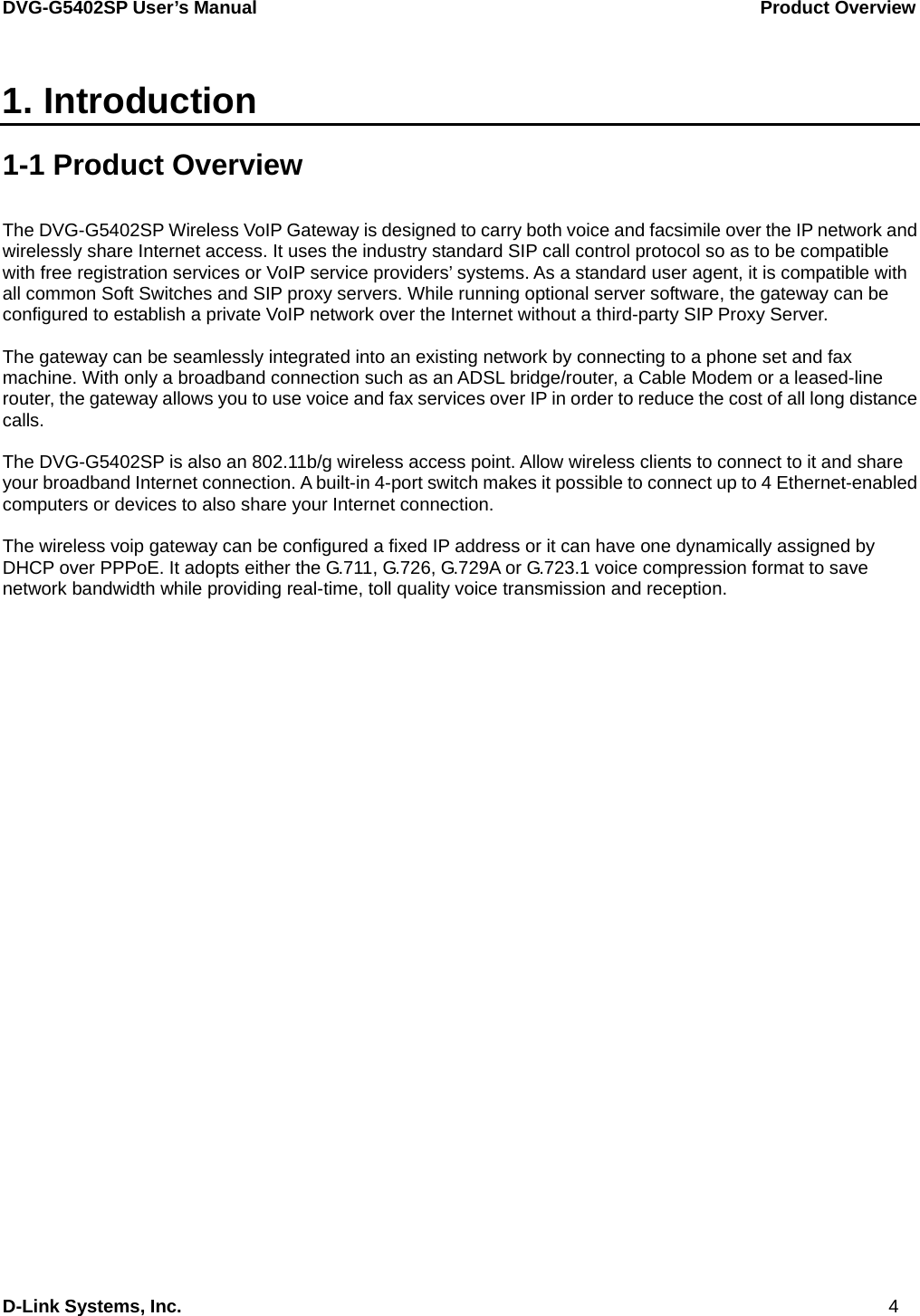
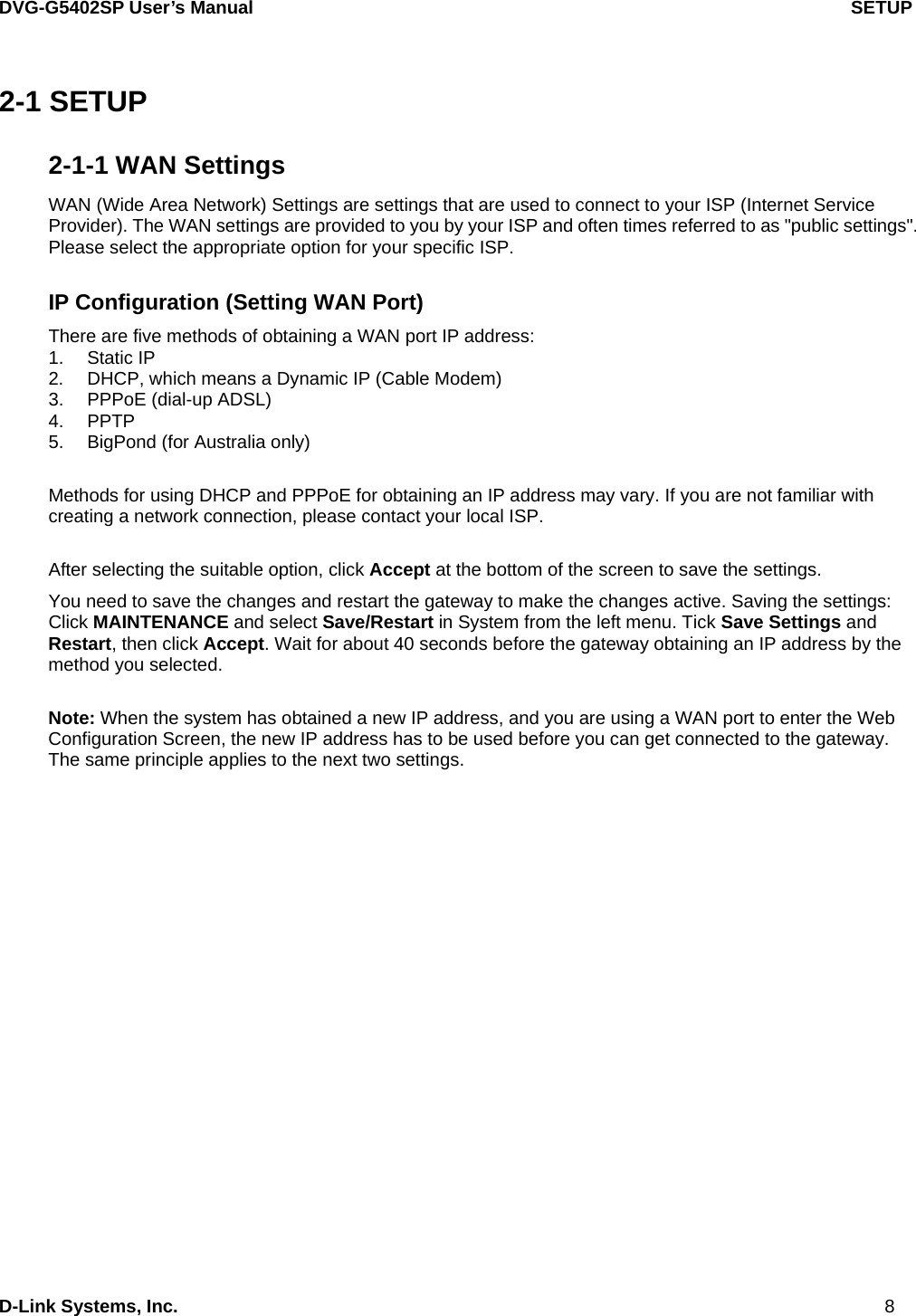
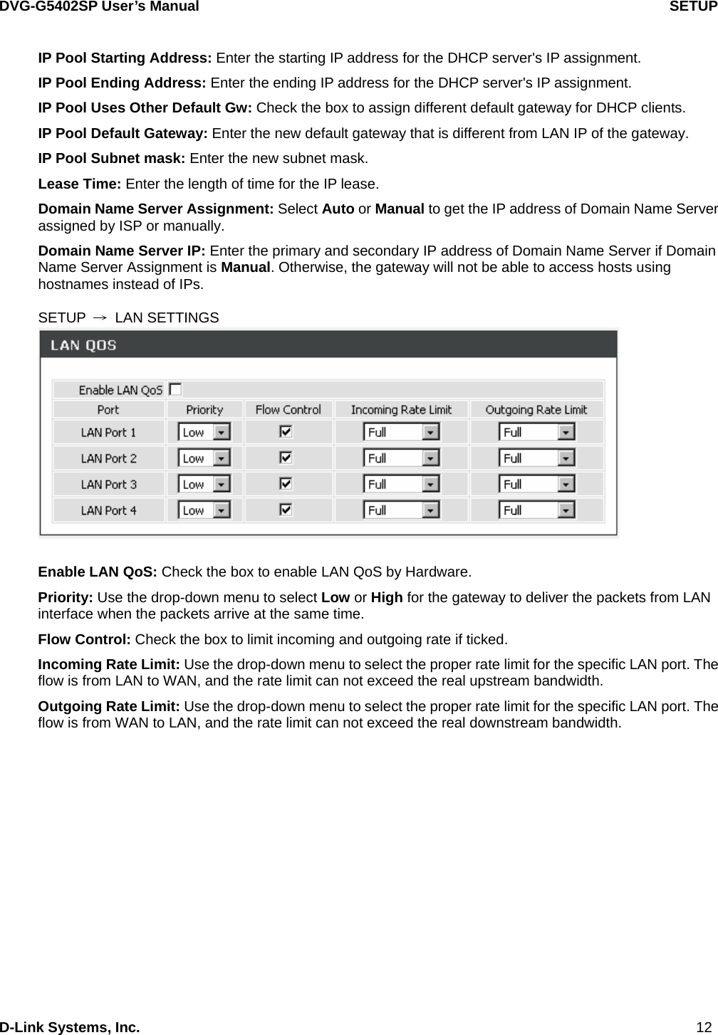
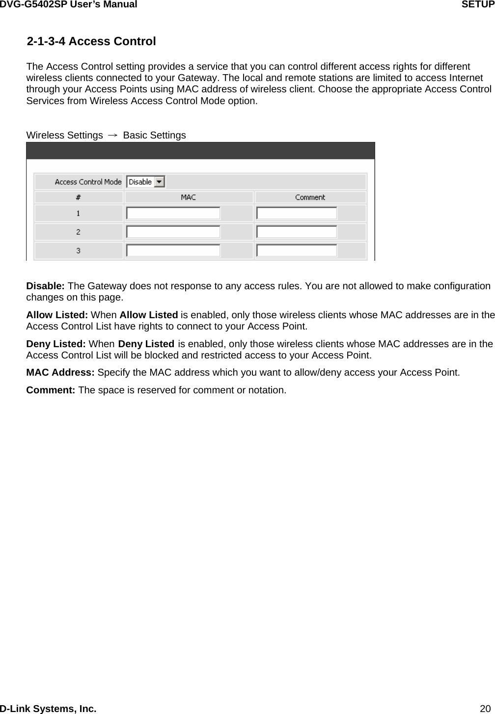
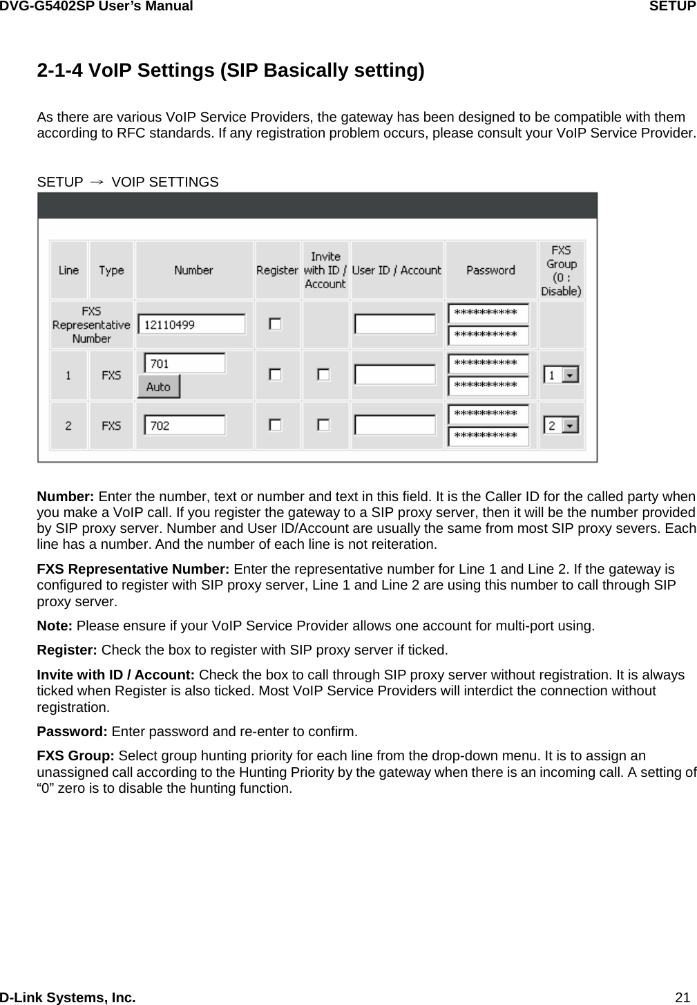
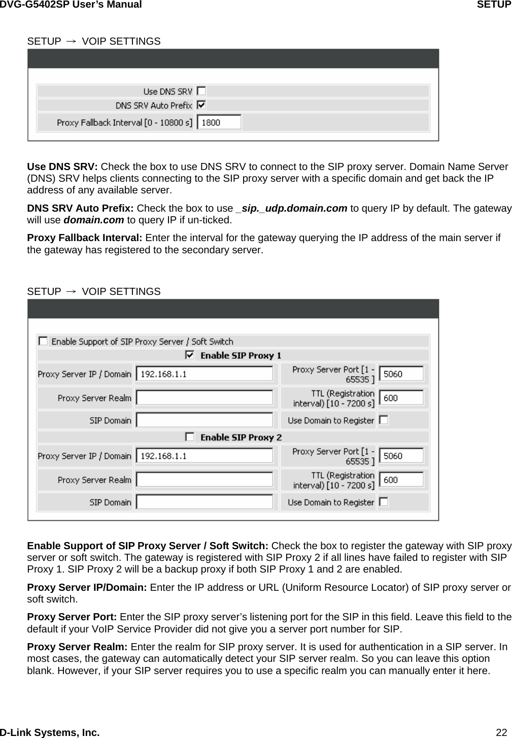
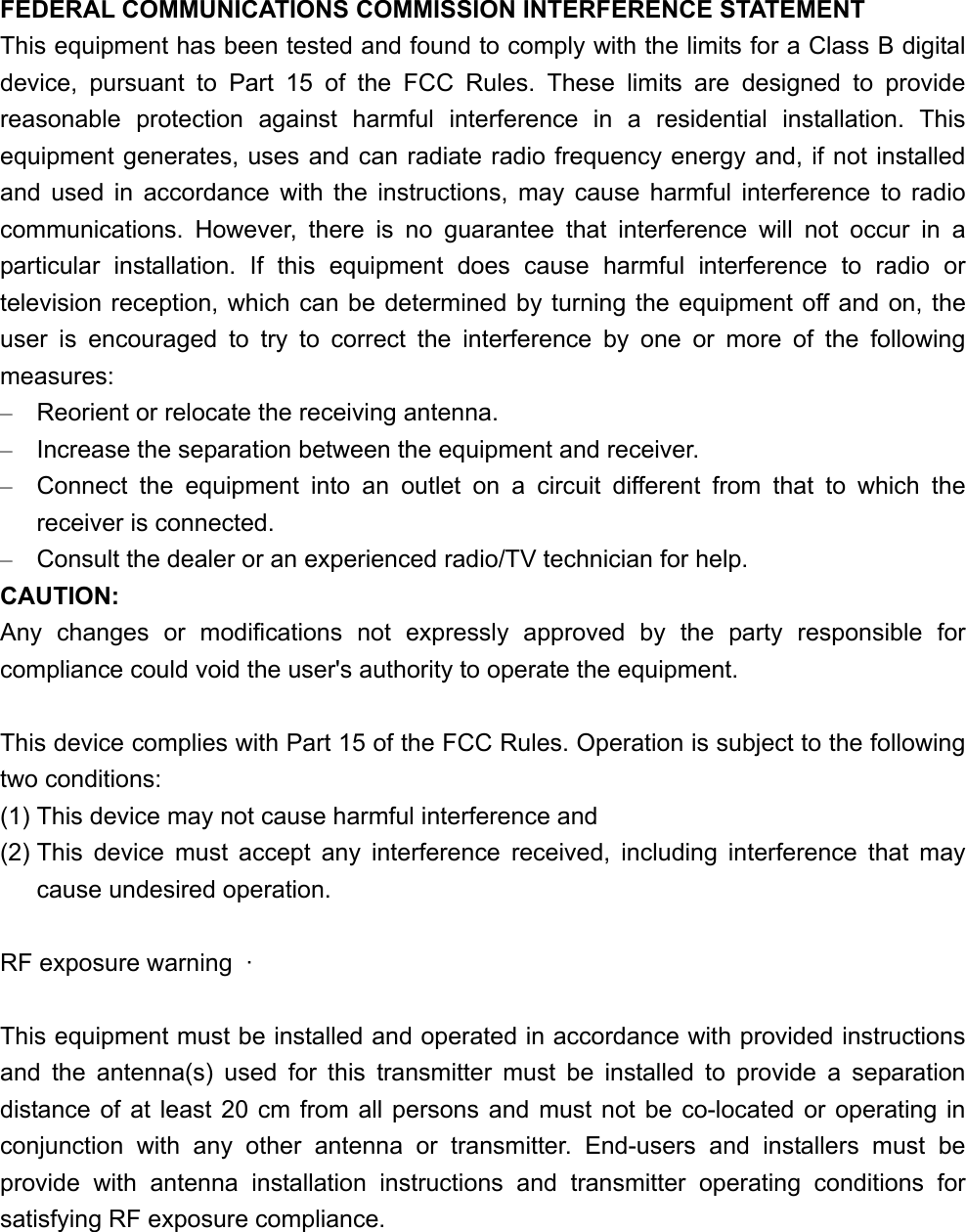
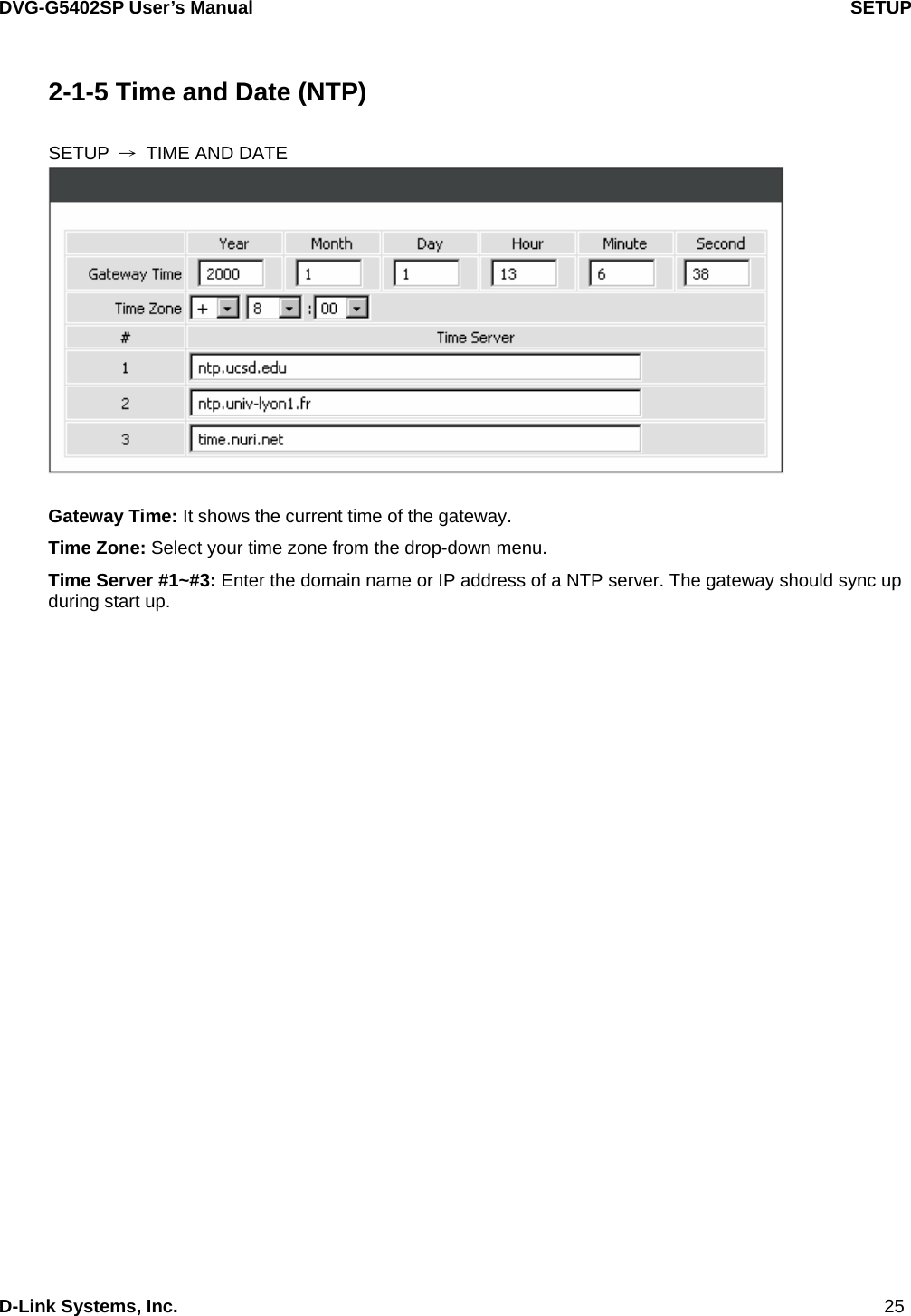
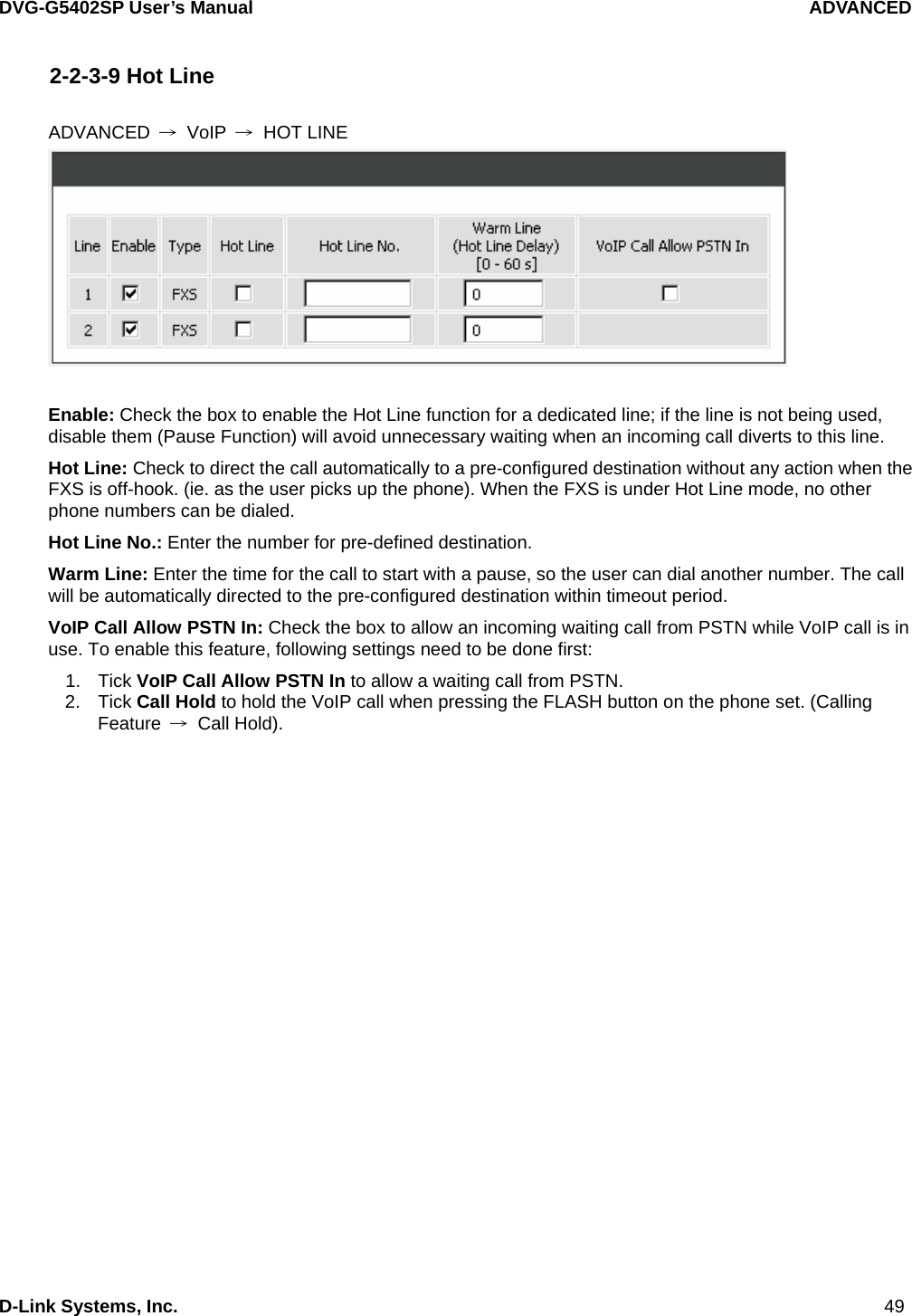
![DVG-G5402SP User’s Manual SETUP D-Link Systems, Inc. 23 TTL (Registration interval) [10-7200 s]: Enter the desired time interval at which the gateway will report to your SIP proxy server. SIP Domain: Enter the SIP domain provided by your VoIP Service Provider. (Note that some SIP proxy servers might not require this.) If you enable “Uses Domain to Register”, the gateway will register to the SIP proxy server with the domain name you filled in. Otherwise, the gateway will register to a SIP proxy server with the IP it resolves. Use Domain to Register: Check the box to use Domain to register with SIP proxy server. The gateway is registered to the SIP proxy server with IP address if un-ticked. Note: Proxy Server Realm, SIP Domain and Use Domain to Register are the parameters provided by VoIP Service Provider. If you fail to make a call, please contact your VoIP Service Provider. SETUP → VOIP SETTINGS Outbound Proxy Support: Check the box to send all SIP packets to the destined outbound proxy server. An outbound proxy server handles SIP call signaling as a standard SIP proxy server would do. Further, it receives and transmits phone conversation traffic (media) between two communication parties. This option tells the gateway to send and receive all SIP packets to the destined outbound proxy server rather than the remote gateway. This helps VoIP calls to pass through any NAT protected network without additional settings or techniques. Please make sure your VoIP Service Provider supports outbound proxy services before you enable it. Outbound Proxy IP/Domain: Enter the outbound proxy’s IP address or URL. Outbound Proxy Port: Enter the outbound proxy’s listening port.](https://usermanual.wiki/D-Link/DVGG5402SP/User-Guide-875001-Page-23.png)
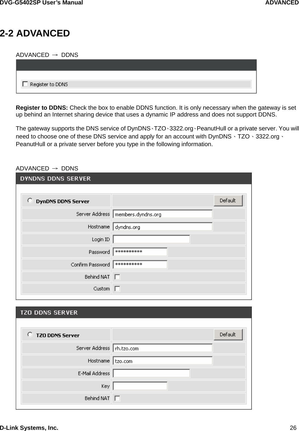
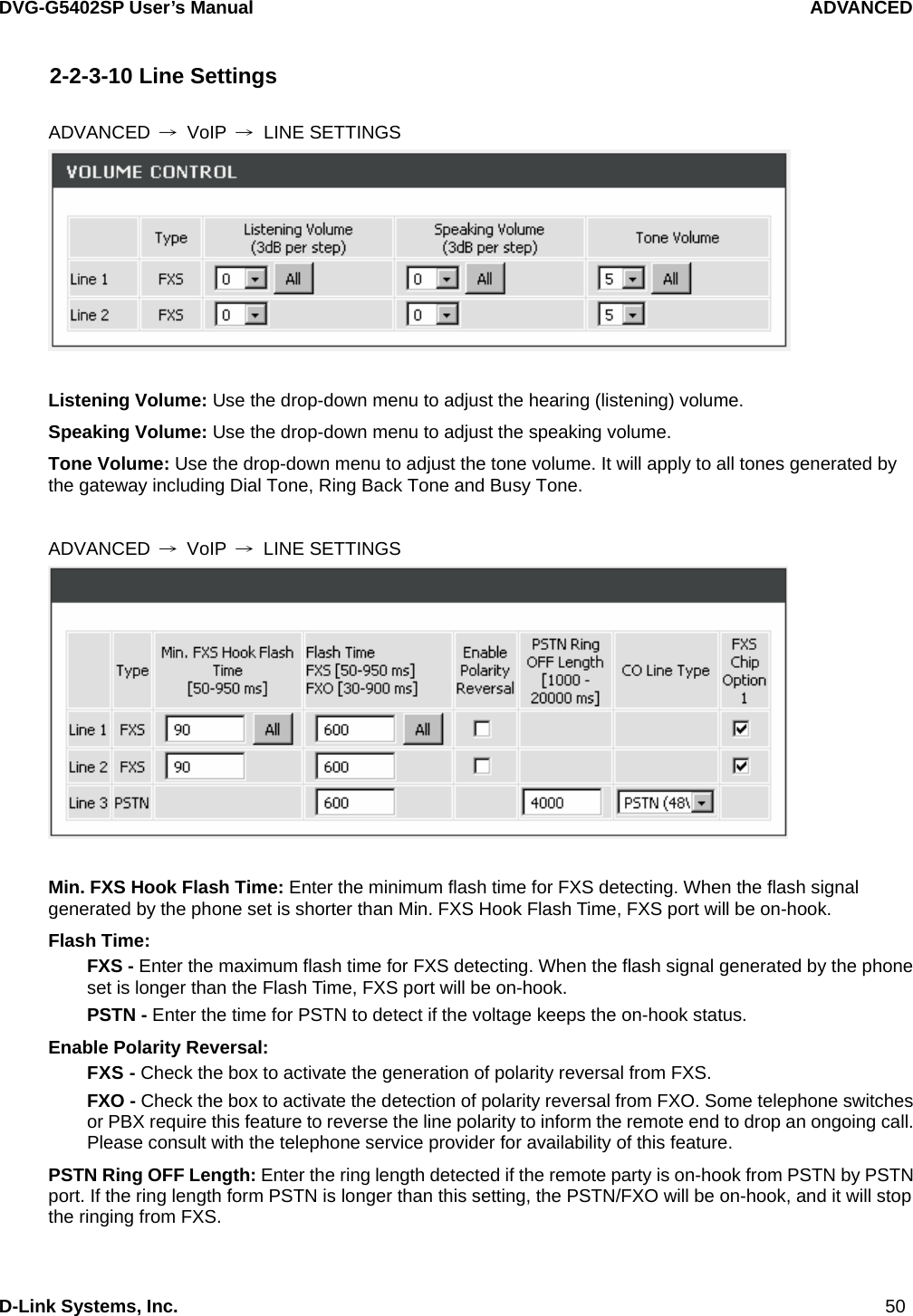
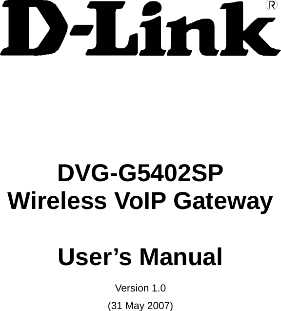
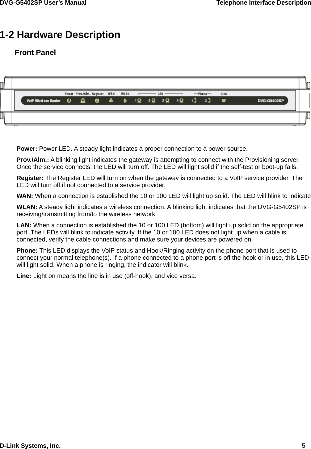
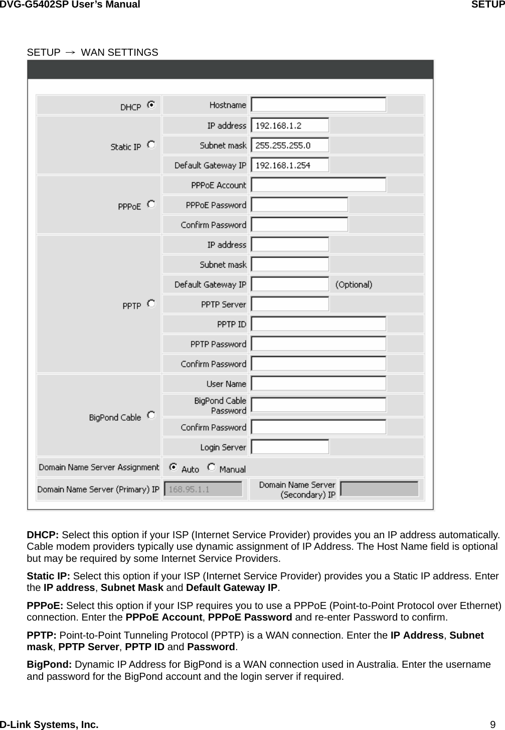
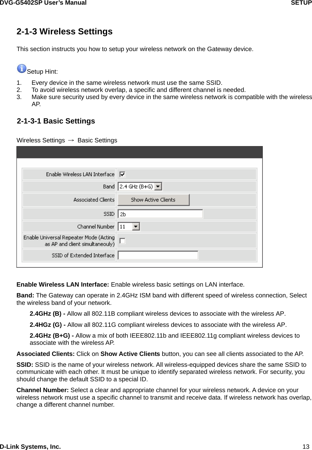
![DVG-G5402SP User’s Manual ADVANCED D-Link Systems, Inc. 51 CO Line Type: Select PSTN (48V) or PABX (24V) for the CO line type connected to PSTN port. FXS Chip Option 1: Check the box to avoid mis-detecting the loop state of a subscriber line or PBX user loop from FXS interface. In some cases, the off-hook voltage might cause the FXS interface mis-detect the idle and the active state, in order to avoid this situation, un-check this feature. ADVANCED → VoIP → LINE SETTINGS Ring (Early Media) Time Limit[10 - 600secs]: Enter the timeout to cancel a call if no one answers the phone. Enable End of Digit Tone: Check the box to activate the function of playing a “Beep-Beep” tone to notify the user that the call is in progress. Force Calling Thru PSTN code: Enter the code to get a PSTN line before dialing out. For example: If you specify code “33” in this option and would like dial “23456789” via a PSTN line: Dial “33” and you will hear dial tone from the PSTN line, now you’re able to dial “23456789” via PSTN line. Early Media Treatment: Check the box to send the one-way RTP immediately when a connection with a VoIP service provider has been set up. Loop Current Drop Trigger Time: Enter the time to avoid the line being engaged when FXS port is connected to PBX. It stops the loop current from FXS port when FXS port is playing busy tone. The setting “0” zero is to disable this function. Loop Current Drop Duration: Enter the drop duration for loop current. Enable ROH: Check the box to play Receiver Off-Hook tone in order to notify user to hang up the phone set if FXS is off-hook for more than 20 seconds.](https://usermanual.wiki/D-Link/DVGG5402SP/User-Guide-875001-Page-51.png)
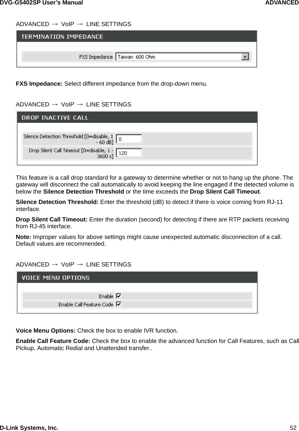
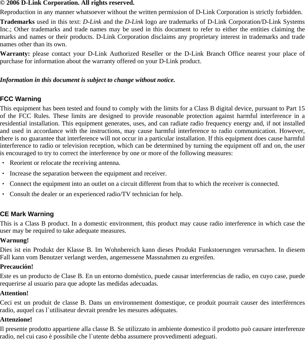
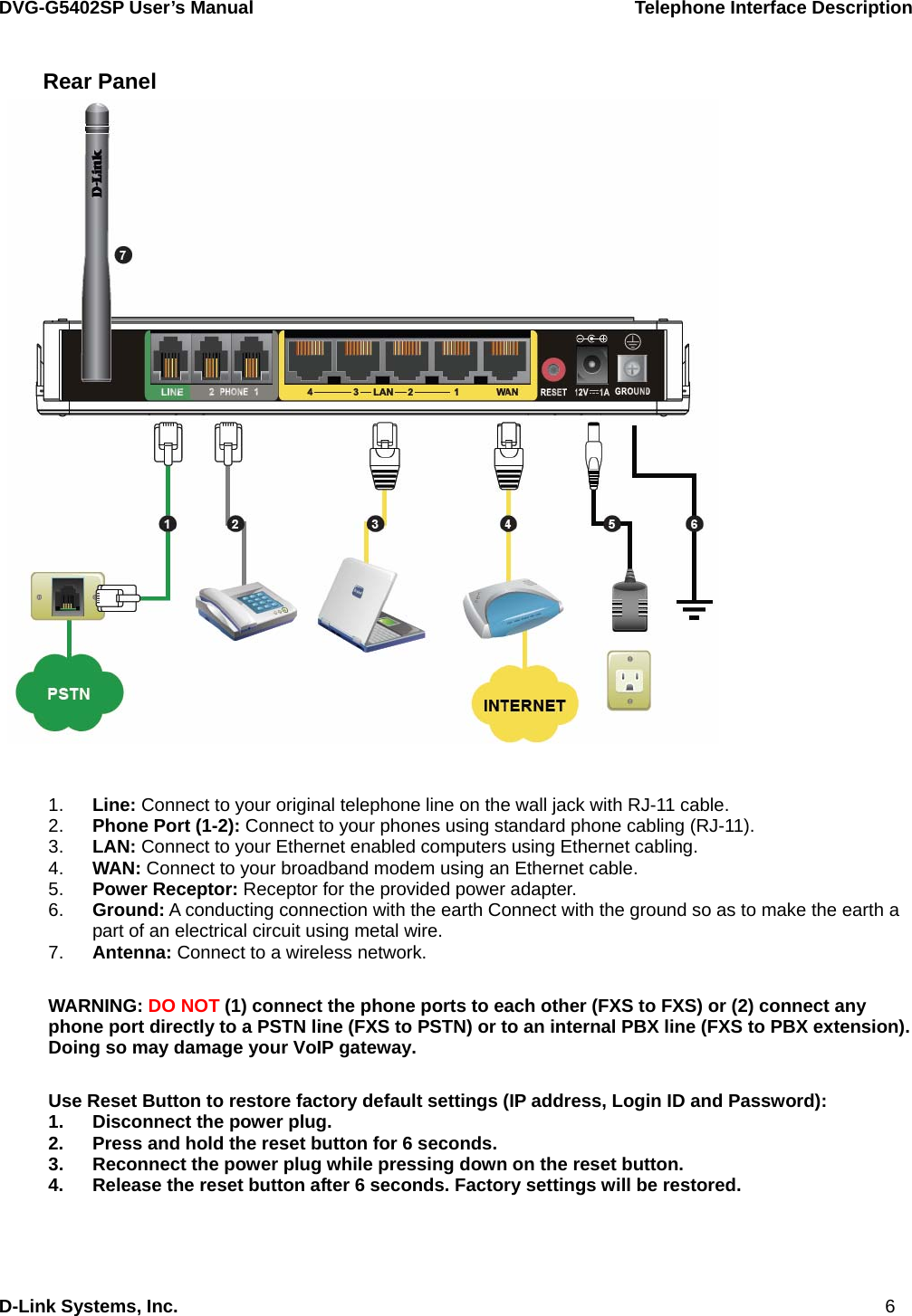
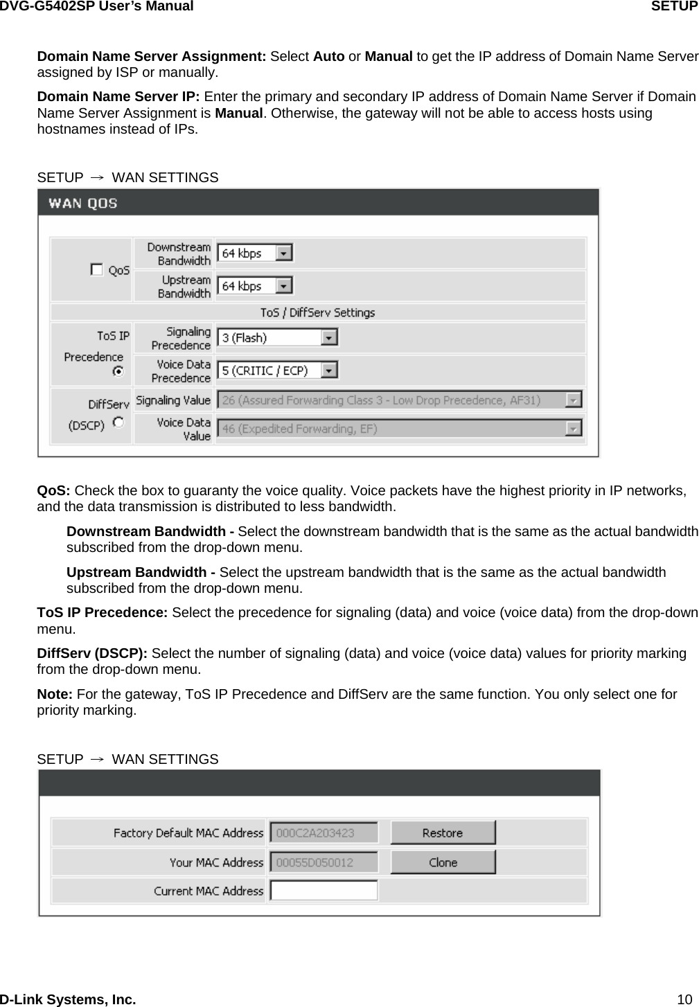
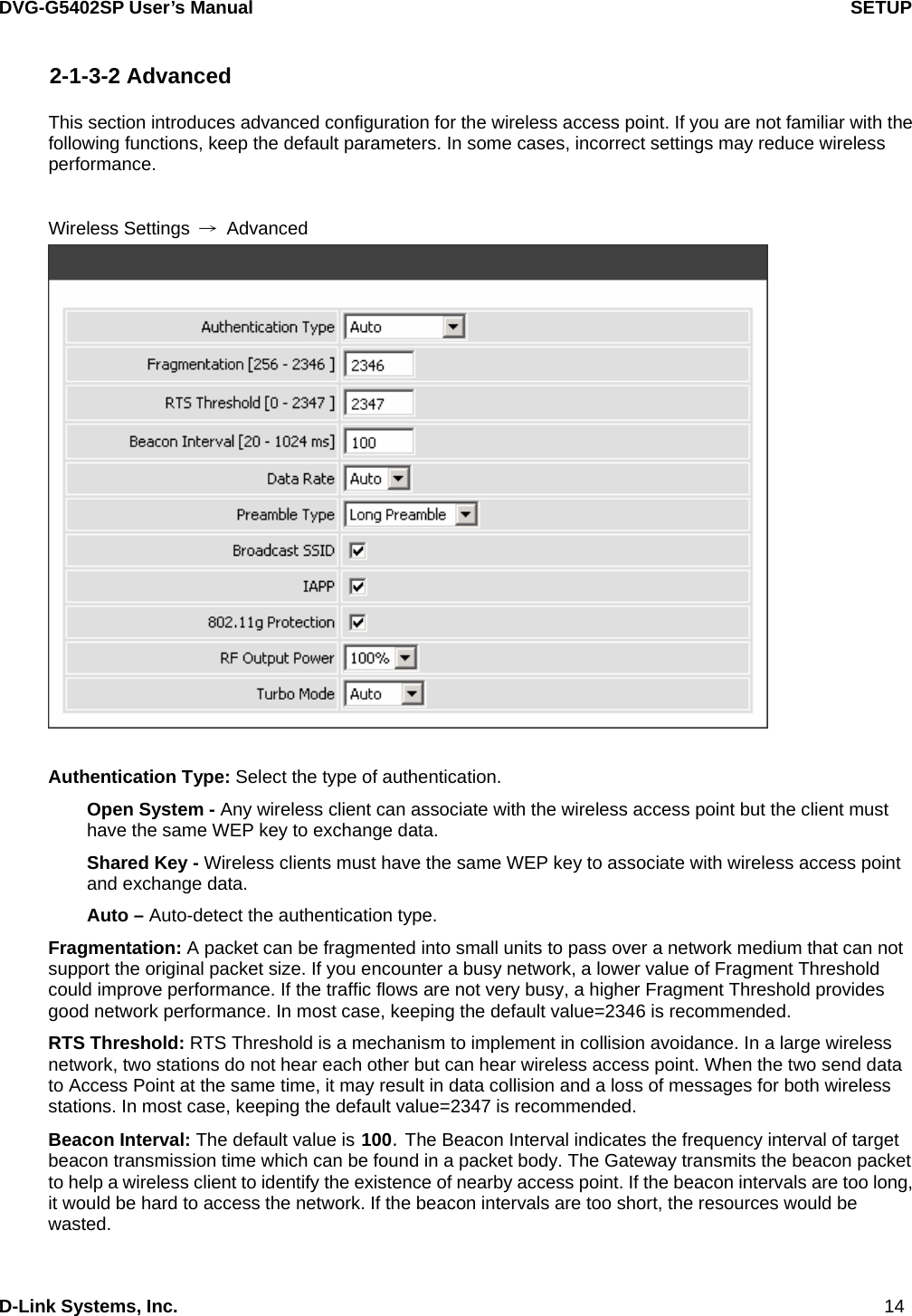
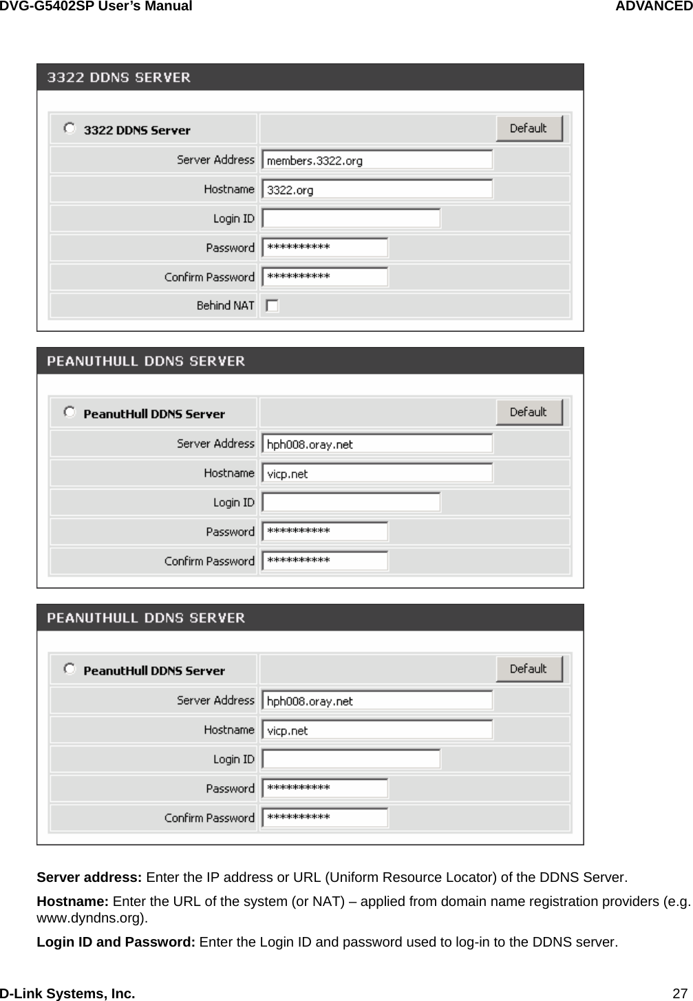
![DVG-G5402SP User’s Manual ADVANCED D-Link Systems, Inc. 57 Invite URL need ‘user=phone’: Check the box to add ‘user=phone’ as a hint that the part left to the '@' sign is actually a phone number. Reliability of Provisional Responses: Check the box to send a PRACK request during the progress of the request processing. Reliability of Provisional Responses is to ACK at every SIP packet. With this method, SIP packet will act like TCP, ie. every packet sent will receive an ACK to make sure that packet sent has been received by other peer. Compact Form: Check the box to represent common header field names in an abbreviated form. This may be useful when SIP message is too large to be carried on and recognized by the user agent. SIP CallerId Obtaining: Select the part of the SIP packet from the gateway to obtain Caller ID. There are several places where the Caller ID is located. Remote-Party-Id Display Name - It is located at SIP → Remote-Party-ID → Before [<sip:] Remote-Party-Id User Name - It is located at SIP → Remote-Party-ID → After [<sip:], Before [@] From-Header Display Name - The standard is in SIP → Message Header → From → SIP Display info. Put Caller ID In URI: This feature is to put Caller ID in URL. The Caller ID is located in SIP → Message Header → After [From:], Before [<sip:] by default settings. It will be located in SIP → Message Header → After [<sip:], Before [@]if ticked. INVITE With Remote-Party-ID Header: Check the box to comprise the information of Remote-Party-ID in the message header of INVITE. Different format of INVITE header might cause the call not to be connected. Please consult with your VoIP Service Provider before enabling it. Support URI Percent-Encoding(RFC 3986): Check the box to encode/decode the letters of the basic Latin alphabet, digits, and a few special characters which follow RFC 3986.](https://usermanual.wiki/D-Link/DVGG5402SP/User-Guide-875001-Page-57.png)
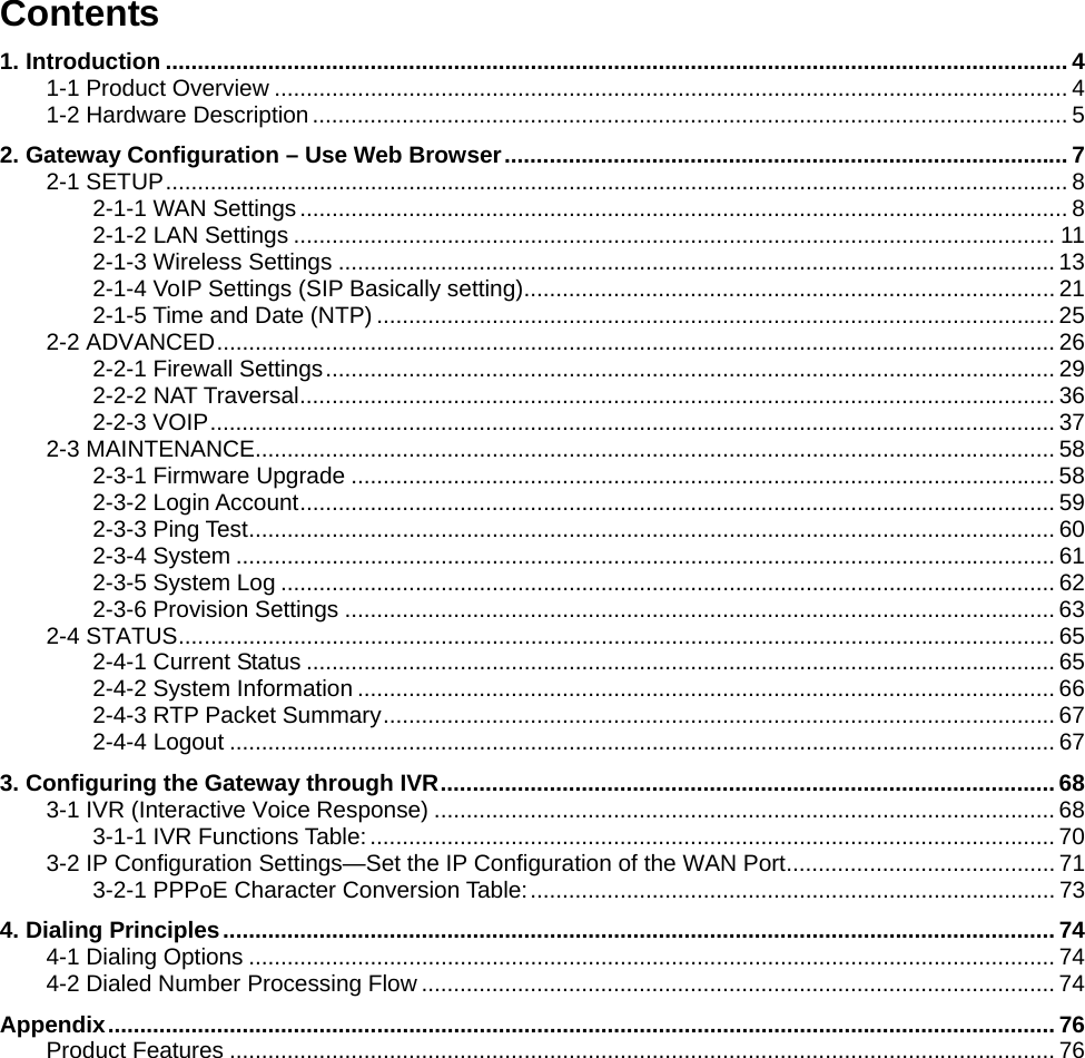
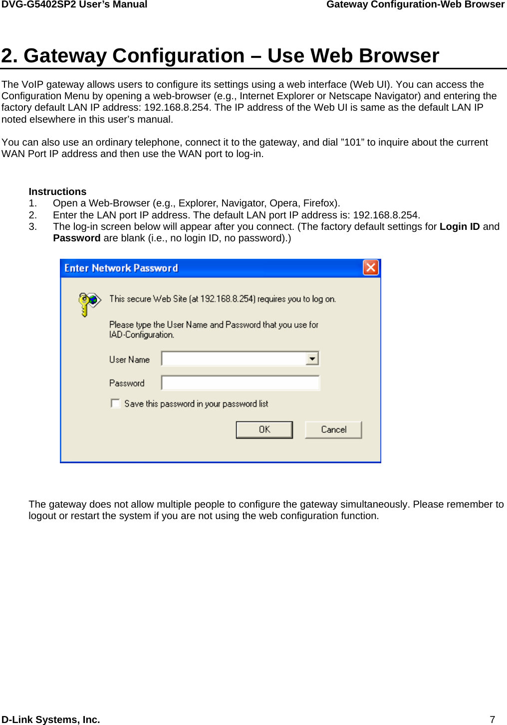
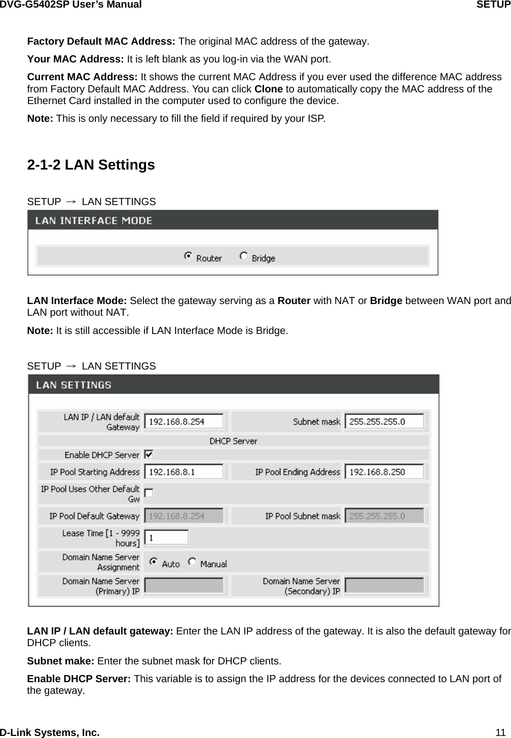
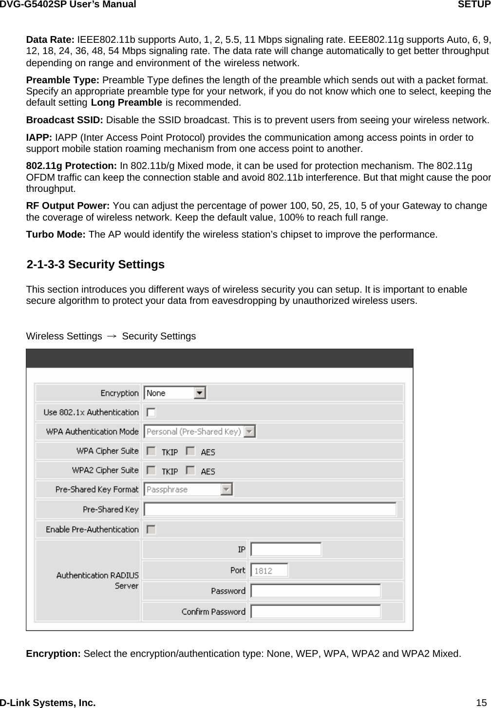
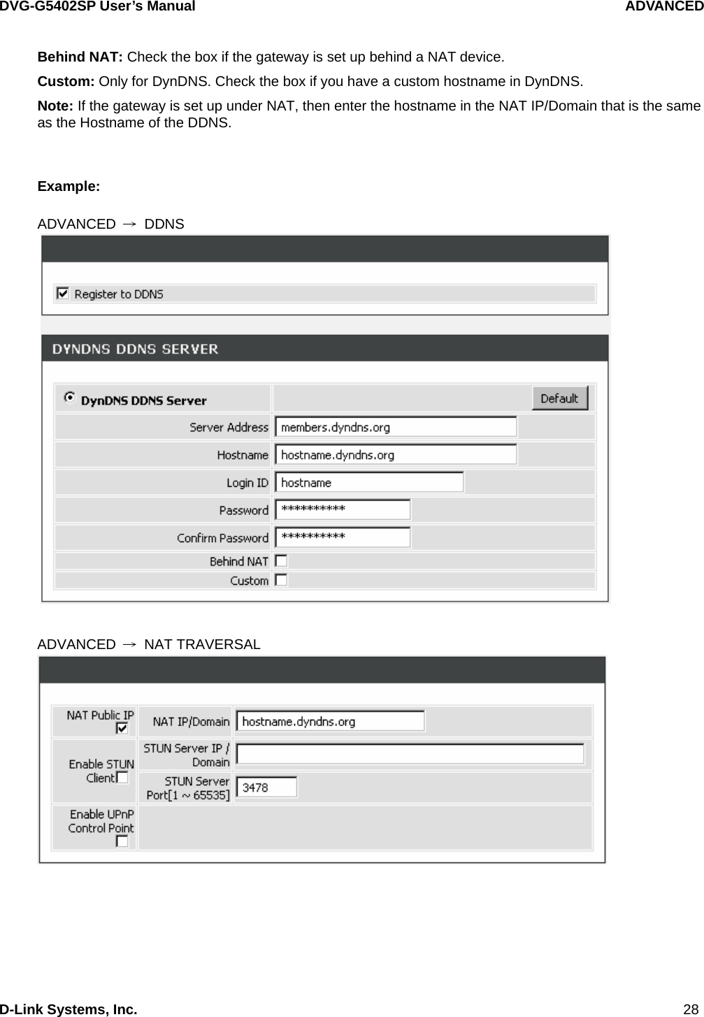
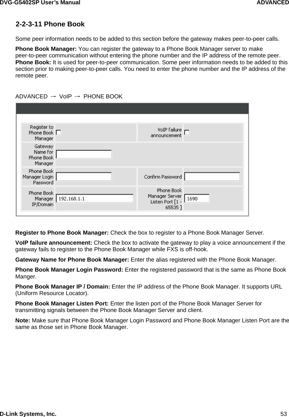
![DVG-G5402SP User’s Manual Gateway Configuration-IVR D-Link Systems, Inc. 73 3-2-1 PPPoE Character Conversion Table: The table below provides a list of PPPoE conversion codes. The first row (high-lighted) of each pair of the column lists the numbers, alphabets or symbols and the second row (high-lighted) of each pair of the column (“Input Key”) represents the codes to be entered for the corresponding numbers, alphabets or symbols. For example, to enter “D-Link” according to the table below, enter: 148322495451 Numbers Input Key Upper Case Letters Input Key Lower Case Letters Input Key Symbols Input Key0 00 A 11 a 41 @ 71 1 01 B 12 b 42 • 72 2 02 C 13 c 43 ! 73 3 03 D 14 d 44 " 74 4 04 E 15 e 45 $ 75 5 05 F 16 f 46 % 76 6 06 G 17 g 47 & 77 7 07 H 18 h 48 ' 78 8 08 I 19 i 49 ( 79 9 09 J 20 j 50 ) 80 K 21 k 51 + 81 L 22 l 52 , 82 M 23 m 53 - 83 N 24 n 54 / 84 O 25 o 55 : 85 P 26 p 56 ; 86 Q 27 q 57 < 87 R 28 r 58 = 88 S 29 s 59 > 89 T 30 t 60 ? 90 U 31 u 61 [ 91 V 32 v 62 \ 92 W 33 w 63 ] 93 X 34 x 64 ^ 94 Y 35 y 65 _ 95 Z 36 z 66 { 96 | 97 } 98](https://usermanual.wiki/D-Link/DVGG5402SP/User-Guide-875001-Page-73.png)