D Link DW1100 Access Point User Manual users manual
D Link Corporation Access Point users manual
D Link >
users manual
- 1 -
DW-1100 Access Point
User’s Guide
- 2 -
Introduction
The DW-1100 (IEEE 802.11b compatible 11 Mbps WLAN Access Point) is a long-range,
high performance LAN product, which provides Access Point services to a 2.4 GHz RF
network and bridges to an Ethernet backbone. DW-1100 is a highly integrated Access Point
designed to combine legacy LANs with wireless LANs. DW-1100 performs all the necessary
inter-networking and bridging functions. It receives data from both networks, stores them
locally for further processing, installs and maintains connections and transmits the packets
to the proper destination. This User Guide describes the steps required for the initial set up
of the AP IP address, the AP configuration, and the firmware upgrade procedure. The
description includes the implementation of the above steps through both Ethernet and USB.
Package
Content
Please make sure that you received the following Content:
! One (1) DW-1100 Access Point
! One USB cable
! One Ethernet cable
! One power adapter
! User Guide
! Firmware, Drivers, and Software Tools CD
System
Requirement
For configuration through USB:
! Operating System: MS Windows ® 98, Windows ® 2000
! Desktop PC or notebook PC with USB port
For configuration through Ethernet:
! Operating System: MS Windows ® 95 OSR2, Windows ®98,
Windows ® 2000, Windows ® NT 4.0
! Desktop PC or notebook PC connected on a LAN
Features The features of the DW-1100 Access Point are the following:
! Povide Ethernet to Wireless LAN bridge fully compatible on
Ethernet side and fully IEEE 802.3 compatible on the Ethernet
side and fully interoperable with IEEE 802.11b compliant
equipment
! Ethernet interface with 10Base-T
! IEEE 802.11b infrastructure and ad hoc operating modes
! Dynamic data rate switching with 11, 5.5, 2 and 1Mbps
! Allows auto fallback data rate for optimized reliability,
throughput and transmission range
! Encryption supporting IEEE 802.11 40-bit or 128-bit Wired
Equivalent Privacy (WEP)
! Dual diversity antennas for the multi-path environment
! Firmware upgrade capability via USB port
! Web-based configuration and management
- 3 -
AP Configuration
The DW-1100 AP configuration can be done through the Ethernet port either by using the
SNMP Manager application or through the USB port by using the AP Utility Application. In
order to configure the DW-1100 AP through the Ethernet Port/Wireless Port, you must first
install the SNMP Manager application, which is a powerful and reliable tool used for the
remote configuration of the Access Point through the Ethernet Port/Wireless Port. In order to
install the SNMP Manager you need to run the program “setup.exe” which you will find in the
“Utilities” folder in your CD. Follow the instructions of the set-up program and select the
directory where the application will be installed. Finally, a window appears indicating the
completion of the installation.
Connecting to AP using SNMP
1. On the Start Menu, choose Start -> Programs -> SNMP Manager.
2. File menu: When the application opens, under the File Menu there are the following
submenus:
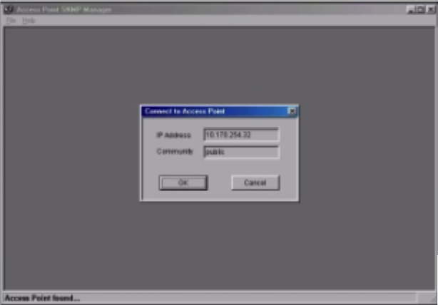
3. Connect to AP - Using this submenu you can directly connect with the Access Point by
typing its IP Address in the panel that appears and at the Community field, type "public"
and then press OK (Figure 1).
Figure 1 Connecting to Access Point using SNMP Manager
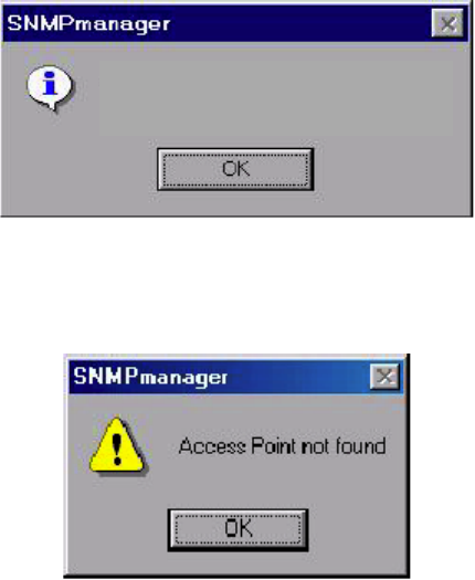
4. In case of a successful connection to the Access Point, the following window appears.
Press “OK” (Figure 2).
- 4 -
DW-1000 Wireless Network Found
(version 1.4)
Figure 2 Access Point Found
5. In case of an unsuccessful connection you receive the following message (Figure 3):
Figure 3 Access Point Not Found
6. If the above error message appears, you need to check if the AP is connected to the
network.
Configuring the AP using SNMP
1. When the connection has been successfully established, you get a message in the left
bottom corner indicating, “Get Configuration done” and on the right bottom corner the
“IP Address” of the connected Access Point.
2. File menu: The file menu contains the following enabled submenus
" Close Connection AP - Terminates the connection with the Access Point.
" Download Changes - When all the desired values of the parameters have been set
you are able to download the changes (save the changes) to the Access Point by
selecting this submenu.
" Options - Defines the polling interval according to which the SNMP Manager polls the
Access point in order to update the statistics and the Associated Stations List.
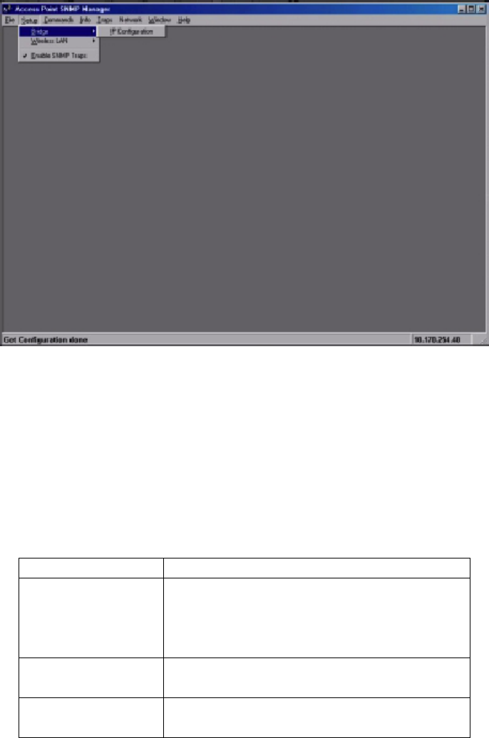
3. Setup menu: As soon as the connection has been established, you are able to start
viewing or setting the Access Point parameters. Under the “Setup” menu, there are the
following submenus:
- 5 -
Figure 4 SNMP Bridge menu and submenus
" Bridge - Under the “Bridge” submenu, the only option is:
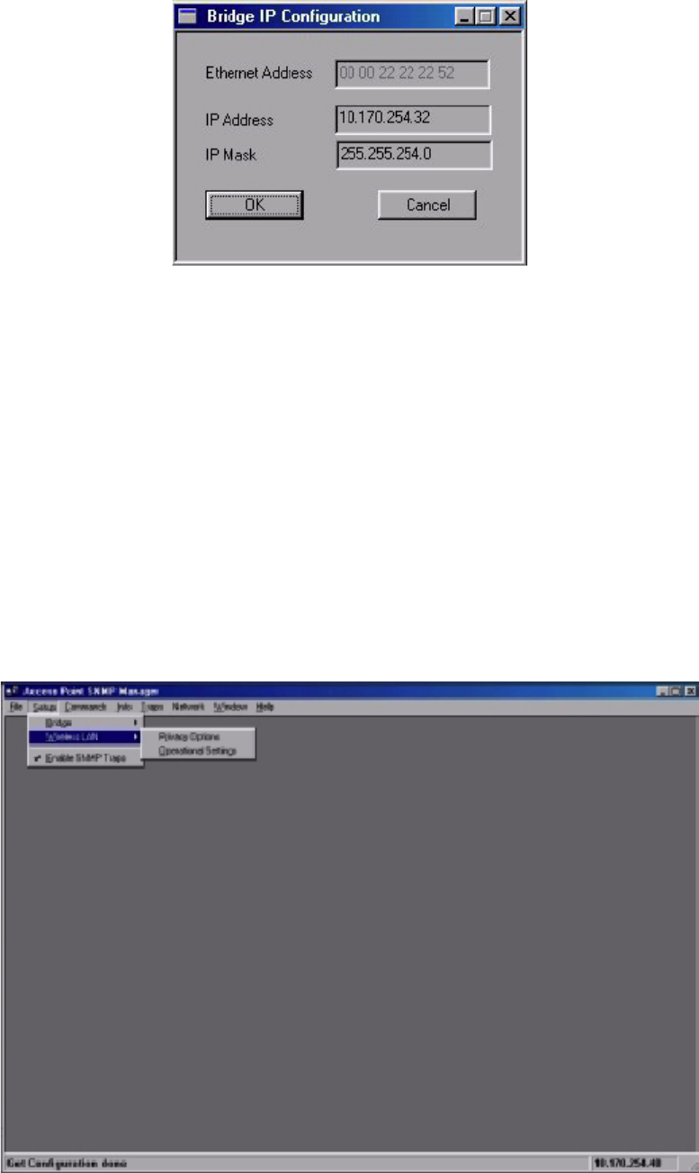
# IP Configuration: By choosing this option the window appears. The “IP Address”
and “IP Mask” can be modified through “IP Configuration”. If changes are made,
you need to “Download Changes” under the “File” menu in order to save them.
Please refer to Table 1 and Figure 5
Parameters Description
Ethernet Address The MAC Address of the Access Point.
Unique 48-bit, hard-coded Media
Access Control address known as the
station identifier.
IP Address Network-assigned Internet Protocol
address of the Access Point.
IP Mask Four sets of three digits that divide a
network into sub networks.
Table 1 Bridge IP Configuration Parameters
- 6 -
Figure 5 Bridge IP Configuration window
" Wireless LAN - Under this submenu there are the following two options available.
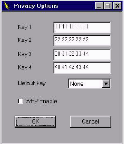
# Privacy Options - By choosing this option you must define the encryption key values
of your choice. There are four 5 Hex digit encryption keys available. The key is
enabled only if you select it in the “Default key” option. Enable the WEP option in
order to activate WEP encryption for transmissions between the station sand the
Access Point. (Figure 6 and Figure 7)
Note: The encryption level must be the same on the wireless station and on the access
point. All shared keys on the wireless station must be the same as those on the access
point with which the client station is associated.
Figure 6 SNMP Wireless LAN menu and submenus
- 7 -
Figure 7 Wireless Privacy Options window
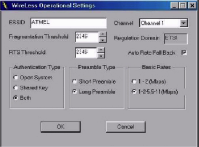
# Operational Settings - Using this option, you can either view or modify the Wireless
LAN parameters of the Access Point (Figure 4-10). These parameters are described
below:
ESSID It is an ASCII string up to 32 characters and it is used to
identify a WLAN that prevents the unintentional merging of
two co-located WLANs. The ESSID value must be the same
in all stations and Access point in the extended WLAN.
Select the ESSID to be used.
Channel There are 14 channels available. The channels differ from
country to country. Select the channel to be used.
Fragmentation
threshold The size at which packets will be fragmented. Choose a
setting within a range of 256 to 2346 bytes.
RTS Threshold Minimum packet size to require an RTS (Request To Send).
For packets smaller than this threshold, an RTS is not sent
and the packet is transmitted directly to the WLAN. This is
the option for the RTS Threshold activation.
Authentication Type Select Open System, Shared Key, or Both
! Open System: With this setting, any station in the
WLAN can associate with an Access Point and receive
and transmitted data (null authentication)
! Shared Key: With this setting only stations using a
- 8 -
shared key encryption identified by the Access Point are
allowed to associate with it.
! Both: with this setting, stations communicate with the
Access Point either with or without data encryption.
Preamble Type
(Short/Long) Preamble is the first sub-field of PPDU, which is the
appropriate frame format for transmission to PHY (Physical
layer). There are two options, Short Preamble and Long
Preamble. The Short Preamble option improves throughput
performance.
Rate: By default, the unit adaptively selects the highest possible
rate for transmission. Select the basic rates to be used
among the following options 1/2 (Mpbs), 1/2/5.5/11 (Mbps).
Auto Rate Fall Back When this is enabled, the transmission rate is the optimum
rate. In case of obstacles or interference, the system will
automatically fall back.
Regulatory Domain The value of this field is already set and cannot be modified.
Figure 8 Wireless Operational Settings window
" Enable SNMP traps - Using this submenu you can either enable or disable SNMP
traps, which are messages displayed in the right bottom corner of the main window
indicating that an action related to the AP took place. Permitted messages are:
! Trap Reassociation: This trap message is sent when a Station’s reassociation
request is received from the AP - Bridge.
! Trap Association: Indicates the reception of an association request packet and
- 9 -
the sender Station's successful association with the Wireless Bridge.
! Trap Disassociation: This trap message is sent when a disassociation notification
packet is received from a Station.
! Trap Reset: This trap message is sent when the AP-Bridge resets.
! Trap Setting IP Address with Ping: This trap message is sent when the AP-Bridge
IP address is set with the transmission of a ping message.
! Trap Start Up: This trap message is sent when Bridge starts up.
! Trap Failed To Erase Flash: This trap message is sent when Bridge fails to erase
flash.
4. Traps menu: Provides information for trap messages
" View Record - You can see additional information for every Trap Message
5. Commands menu: Under this menu there are two submenus.
" Reset Device - You can reset the Access Point. This action takes place after a user
makes configuration changes in order to initiate the changes.
" Restore Default - You can restore the factory default values of the Access Point.
6. Info menu: Using this menu you can view a limited number of statistics
- 10 -
Regulatory Compliance Information
FCC Notice
This device has been tested and found to comply with the limits for a Class A digital device
pursuant to Part 15 of the Federal Communications Commissions Rules and Regulation.
These limits are designed to provide reasonable protection against harmful interference
when the equipment is operated in a commercial environment. This equipment generates,
uses, and can radiate radio frequency energy and, if not installed and used in accordance
with the instruction manual, may cause harmful interference to radio communications.
Operation of this equipment in a residential area is likely to cause harmful interference in
which case the user will be required to correct the interference at his own expense. However,
there is no guarantee that interference will not occur in a particular installation. If the
equipment does cause harmful interference to radio or television reception, which can be
determined by turning the equipment off and on, the user is encouraged to try to correct the
interference by one or more of the following measures:
! Re-orient or relocate the receiving antenna.
! Increase the separation between the equipment and receiver.
! Connect the equipment into an outlet on a circuit different from that which the receiver is
connected.
! Consult the dealer or an experienced radio/TV technician for help.
This device complies with Part 15 of the FCC Rules. Operation is subject to the following
two conditions: (1) this device may not cause harmful interference, and (2) this device must
accept any interference received, including interference that may cause undesired
operation.
FCC Radiation Exposure Statement
This equipment complies with FCC radiation exposure limits set forth for an uncontrolled
environment. This equipment should be installed and operated with minimum distance 20cm
between the radiator and your body.
- 11 -
European Notice
Equipment with CE marking complies with the R&TTE Directive (1999/5/EC), EMC Directive
(89/336/EEC) and the Low Voltage Directive (73/23/EEC) issued by the European
Community. Compliance with these directives implies conformity to the following European
Norms or Regulations (in parentheses are the equivalent international standards and
regulations):
! EN 55022 (CISPR 22) – Electromagnetic Interference
! EN 50082-1 (IEC 801-2, IEC 801-3, IEC 802-4) – Electromagnetic Immunity
! EN 60950 (IEC 60950) – Product Safety
! ETS 300 326 – Technical characteristics and test conditions for data transmission
equipment operating in the 2.4GHz ISM band and using spread spectrum modulation
techniques
! ETS 300 826 – Electromagnetic Compatibility (EMC) standard for 2.4GHz wide band
transmission systems and High Performance Local Area Network (HIPERLAN)
equipment
This product may be used in the following EU and EFTA countries: Austria, Belgium,
Denmark, Finland, Germany, Greece, Iceland, Ireland, Italy, Liechtenstein, Luxembourg,
Netherlands, Norway, Portugal, Sweden, Switzerland and United Kingdom. Products not
marked with “Not for use in France” may be used in France.
- 12 -
Specifications
Radio Technology IEEE 802.11b Direct Sequence Spread Spectrum
Operating Frequency 2400-2497MHz ISM band
Modulation Schemes DQPSK, DBPSK and CCK
Channel Available 11 channels for United States
13 channels for Europe
14 channels for Japan
Data Rate 11Mbps with fall back rates of 5.5, 2 and 1Mbps
Media Access Protocol CSMA/CA with ACK
Power Density 3mW/MHz
Antenna Gain 0~1dBi
Antenna Type External dipole antenna
Power 5VDC / 1A
Interface RJ-45 for 10Base-T Ethernet
USB for configuration
Range Coverage Indoor: 35 - 100 meters (depends on environment)
Outdoor: 100 - 300 meters (depends on environment)
LED Indicator Power, RF activity, and Ethernet LEDs