D Link DWL-510A1 802.1 lb WIRELESS PCI ADAPTOR User Manual WLB 1200 v101
D Link Corporation 802.1 lb WIRELESS PCI ADAPTOR WLB 1200 v101
UserManual.wiki
>
D Link
>
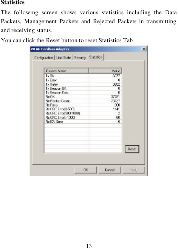
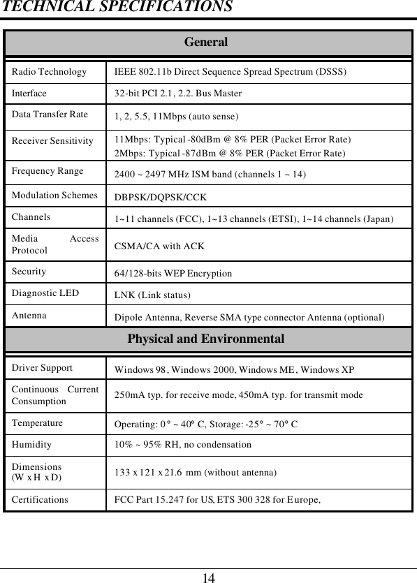
DWL 510A1 User Manual
MANUAL
Navigation menu
Upload a User Manual
Namespaces
Wiki Guide
HTML
PDF
Info
Views
User Manual
Discussion / Help
Navigation