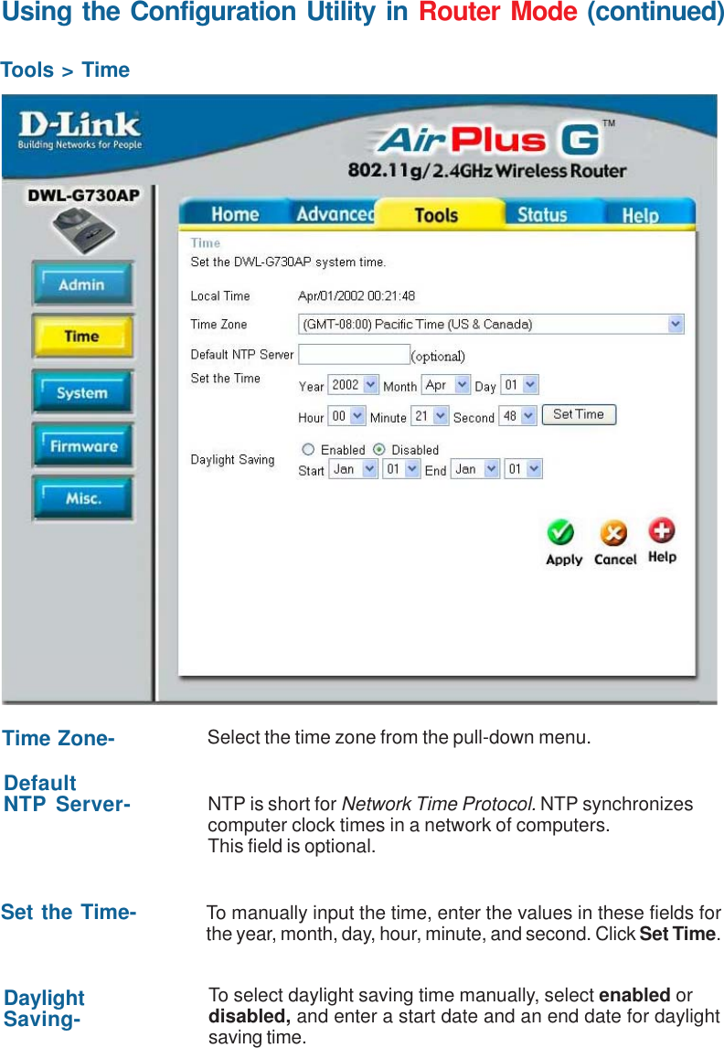
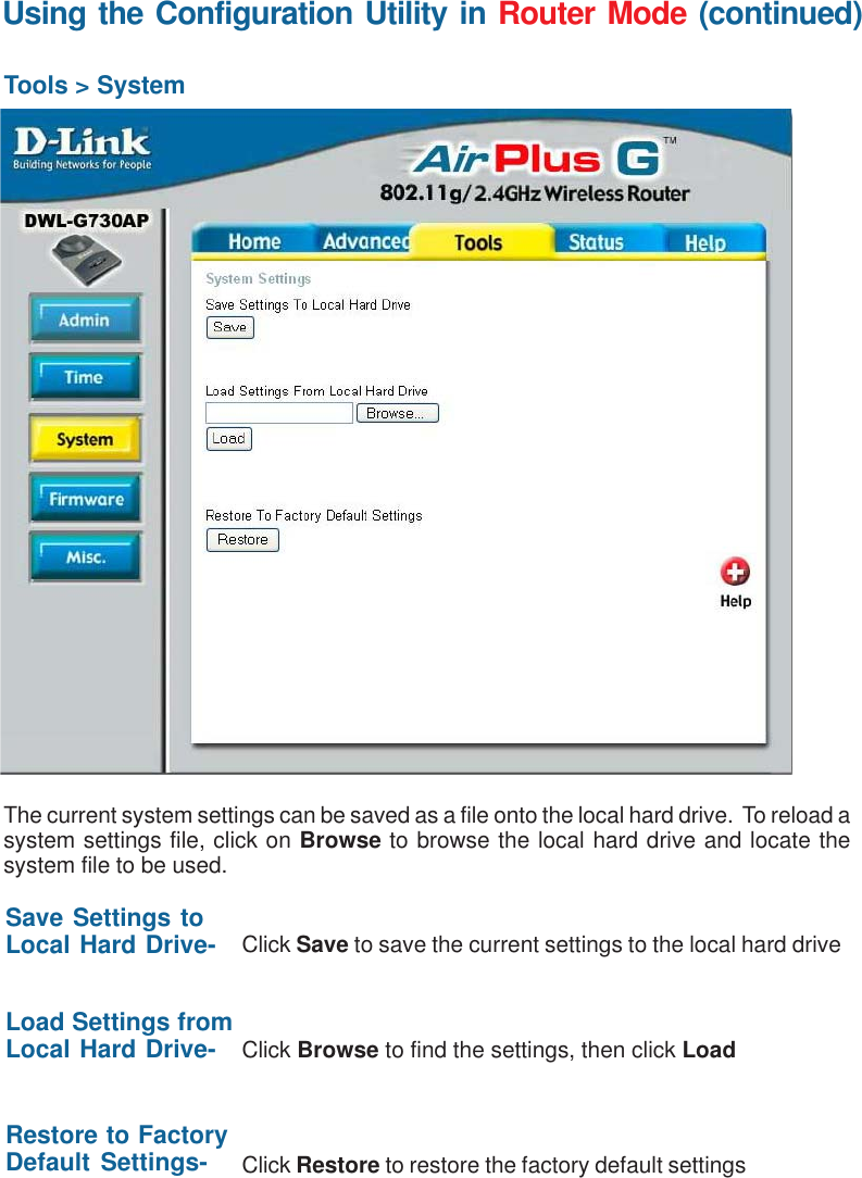
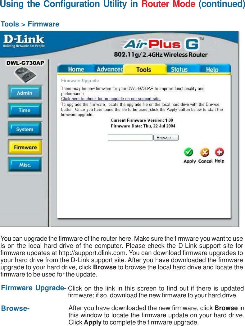
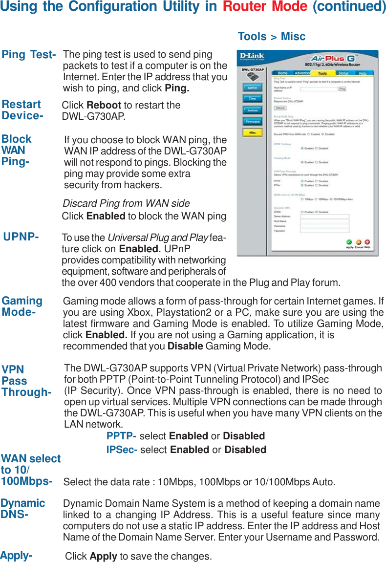
D Link DWLG730APB1 802.11g Wireless AP User Manual dwl700ap manual 061203

D Link Corporation 802.11g Wireless AP dwl700ap manual 061203

Contents

Manual 2

41Using the Configuration Utility in Router Mode (continued)Advanced > Virtual ServerThe DWL-G730AP can be configured as a virtual server so that remote users accessingWeb or FTP services via the public IP address can be automatically redirected to localservers in the LAN (Local Area Network).The DWL-G730AP firewall feature filters out unrecognized packets to protect your LANnetwork so all computers networked with the DWL-G730AP are invisible to the outsideworld. If you wish, you can make some of the LAN computers accessible from theInternet by enabling Virtual Server. Depending on the requested service, the DWL-G730APredirects the external service request to the appropriate server within the LAN network.The DWL-G730AP is also capable of port-redirection meaning incoming traffic to aparticular port may be redirected to a different port on the server computer.Each virtual service that is created will be listed at the bottom of the screen in the VirtualServers List. There are pre-defined virtual services already in the table. You may usethem by enabling them and assigning the server IP to use that particular virtual service.
42Using the Configuration Utility in Router Mode (continued)Advanced > Virtual Server (continued)Example #1:Protocol Type- The protocol used for the virtual service.Public Port- The port number on the WAN (Wide Area Network) side that willbe used to access the virtual service.Private Port- The port number of the service used by the Private IP computer.Schedule- The schedule of time when the virtual service will be enabled.The schedule may be set to Always, which will allow theparticular service to always be enabled. If it is set to From,select the time frame for the service to be enabled. If thesystem time is outside of the scheduled time, the service willbe disabled.Virtual Server- Select Enabled or Disabled.Name- Enter the name referencing the virtual service.Private IP- The server computer in the LAN (Local Area Network) that will beproviding the virtual services.If you have a Web server that you wanted Internet users toaccess at all times, you would need to enable it. Web(HTTP) server is on LAN (Local Area Network) computer192.168.0.25. HTTP uses port 80, TCP.Name: Web ServerPrivate IP: 192.168.0.25Protocol Type: TCPPrivate Port: 80Public Port: 80Schedule: always
43Using the Configuration Utility in Router Mode (continued)Advanced > Virtual Server (continued) Example #2:If you have an FTP server that you wanted Internet users to access by WAN port 2100and only during the weekends, you would need to enable it as such. FTP server is onLAN computer 192.168.0.30. FTP uses port 21, TCP.Name: FTP ServerPrivate IP: 192.168.0.30Protocol Type: TCPPrivate Port: 21Public Port: 2100Schedule: From: 01:00AM to 01:00AM, Sat to SunClick on this icon to edit the virtual serviceClick on this icon to delete the virtual serviceAll Internet users who want to access this FTP Servermust connect to it from port 2100. This is an example ofport redirection and can be useful in cases where thereare many of the same servers on the LAN network.
44Using the Configuration Utility in Router Mode (continued)Advanced > ApplicationsSome applications suchas Internet gaming, videoconferencing, Internettelephony and others,require multipleconnections. Theseapplications savedifficulties workingthrough NAT (NetworkAddress Translation).Special Applicationsmakes some of theseapplications work withthe DWL-G730AP. If youneed to run applicationsthat require multipleconnections, specify theport normally associatedwith an application in the“Trigger Port” field, selectthe protocol type as TCPor UDP, then enter the public ports associated with the trigger port to open them forinbound traffic.The DWL-G730AP provides some predefined applications in the table on the bottom ofthe Web page. Select the application you want to use and enable it.Name: This is the name referencing the special application.Trigger Port: This is the port used to trigger the application. It can be eithera single port or a range of ports.Trigger Type: This is the protocol used to trigger the special application.Public Port: This is the port number on the WAN side that will be used toaccess the application. You may define a single port or arange of ports. You can use a comma to add multiple ports orport ranges.Public Type: This is the protocol used for the special application.Note! Only one PC can use each Special Application tunnel.Special Applications List
45Using the Configuration Utility in Router Mode (continued)Advanced > Filters > IP FiltersFilters are used to deny or allow LAN (Local Area Network) computers from accessingthe Internet. The DWL-G730AP can be setup to deny internal computers by their IP orMAC addresses. The DWL-G730AP can also block users from accessing restrictedweb sites.This is the schedule of time when the IP Filter will be enabled.Schedule:Select the protocol typeProtocol Type:Use IP Filters to deny LAN IP addresses from accessing theInternet. You can deny specific port numbers or all ports forthe specific IP address.IP Filters:The single port or port range that will be denied access to theInternet.Port:The IP address of the LAN computer that will be deniedaccess to the Internet.IP:
46Using the Configuration Utility in Router Mode (continued)Advanced > Filters > URL BlockingSelect Enable or Disable. Enter the words or word containedin the URL that you wish to block. Click Apply to activate theURL blocking.URL Blocking:Select the URL block that you want to delete. ClickDelete.Delete:Click Apply to save changes.Apply:
47Using the Configuration Utility in Router Mode (continued)Advanced > Filters > MAC FiltersClick to Disable MAC Filters.Disable MACFilters:Allow only those devices with the listed MAC addressesaccess to the network.Allow:Deny the devices that are listed from accessing the network.Deny:Enter a name for the device.Name:Click Clear to erase the name.Clear:Enter the MAC address manually.MAC Address:Select the DHCP Client from the pull-down list and clickClone to enter the MAC address into the list.Clone:Click Apply to save the changes.Apply:
48Using the Configuration Utility in Router Mode (continued)Advanced > Filters > Domain BlockingClick Disable to disable domain blocking.Disable:Click Allow to allow access to all domains except BlockedDomains.Allow:Click Deny to deny access to all domains except PermittedDomains.Deny:Enter the permitted domains here. Click Apply.PermittedDomains:Enter the blocked domains here. Click Apply.BlockedDomains:Select a domain from either the permitted or blocked domainlist, and click Delete to delete this domain.Delete:
49Using the Configuration Utility in Router Mode (continued)Advanced > FirewallFirewall Rules isan advanced featureused to deny orallow traffic frompassing through theDWL-G730AP. Itworks in the sameway as IP Filterswith additionalsettings. You cancreate more detailedaccess rules for theDWL-G730AP.When virtualservices are createdand enabled, it willalso display inFirewall Rules.Firewall Rulescontain all networkfirewall rulespertaining to IP(Internet Protocol).Firewall Rules- Enable or disable the FirewallName- Enter the nameAction- Allow or DenySource- Enter the IP Address rangeSchedule- Select Always or enter the Time Range.Destination- Enter the IP Address range; the Protocol;and the Port RangeNote:The DWL-G730AP MAC Address filtering rules have precedence overthe Firewall Rules.In the Firewall Rules List at the bottom of the screen,rules are prioritized from the top(highest priority) to the bottom (lowest priority.)
50Using the Configuration Utility in Router Mode (continued)Advanced > DMZIf you have a client PC that cannot run Internet applications properly from behind theDWL-G730AP, then you can set the client up for unrestricted Internet access. Allowinga computer to be exposed to the Internet, this feature is useful for gaming purposes.Enter the IP address of the internal computer that will be the DMZ host. Using the DMZ(Demilitarized Zone) feature may expose your local network to a variety of securityrisks, so only use this option as a last resort.DMZ- Enable or Disable the DMZ. The DMZ (Demilitarized Zone)allows a single computer to be exposed to the internet.  Bydefault the DMZ is disabled.IP Address- Enter the IP Address of the computer to be in the DMZ30
51Beacon Interval: Beacons arepackets sent by an access pointto synchronize a wireless network.Specify a beacon interval value.Default (100) is recommended.RTS Threshold:  This valueshould remain at its defaultsetting of 2432. If you encounterinconsistent data flow, onlyminor modifications to the valuerange between 256 and 2432are recommended.Fragmentation: This valueshould remain at its defaultsetting of 2346. If you experiencea high packet error rate, you may slightly increase your fragmentation threshold withinthe value range of 256 to 2346. Setting the fragmentation threshold too low may result inpoor performance.DTIM Interval (Beacon Rate): (Delivery Traffic Indication Message) Enter a valuebetween 1 and 255  (default is 3) for the Delivery Traffic Indication Message (DTIM.) ADTIM is a countdown informing clients of the next window for listening to broadcast andmulticast messages.TX Rates: Select the transmission rate for the network. The default setting is Auto.Mode Setting: For utmost speed, select G Mode to include only 802.11g devices inyour network. Select Mix Mode to include 802.11g and 802.11b devices in your network.Preamble: Short Preamble is the default setting. (High traffic networks should usethe shorter preamble type.) The preamble defines the length of the CRC block (CyclicRedundancy Check is a common technique for detecting data transmission errors) usedin communication between the access point and the wireless network adapters.Using the Configuration Utility in Router Mode (continued)Advanced > PerformanceSSID Broadcast:  (Service Set Identifier) Enable or Disable (default) the broadcast ofthe SSID name across the network. SSID is a name that identifies a wireless network.All devices on a network must use the same SSID to establish communication.Antenna Transmit Power: Select the transmission power of the antenna. Limitingantenna power can be useful for security purposes.Authentication:Select Open System to communicate the key across the network.Select Shared Key to limit communication only to those devices that share thesame WEP settings.Select WPA-PSK to select Wi-Fi Protected Access without a RADIUS server.
52Using the Configuration Utility in Router Mode (continued)Tools > AdminAt this page, the DWL-G730AP administrator can change the system password. Thereare two accounts that can access the router’s Web-management interface. They areadmin and user. Admin has read/write access while user has read-only access. Theuser can only view the settings but cannot make any changes.Remote Management- Remote management allows the DWL-G730AP to beconfigured from the Internet by a Web browser. A username and password is still requiredto access the Web-management interface. In general, only a member of your networkcan browse the built-in Web pages to perform Administrator tasks. This feature enablesyou to perform Administrator tasks from the remote (Internet) host.IP Address- The Internet IP address of the computer that has access to the router. Ifyou input an asterisk (*) into this field, then any computer will be able to access therouter. Putting an asterisk (*) into this field would present a security risk and is notrecommended.Port- The port number used to access the router.Example- http://x.x.x.x:8080 where x.x.x.x is the WAN IP address of the router and8080 is the port used for the Web-mangement interface.Administrator-Password-admin is the Administrator login nameEnter the password and enter again to confirmUser-Password-user is the User login nameEnter the password and enter again to confirm
53Using the Configuration Utility in Router Mode (continued)Tools > TimeTime Zone- Select the time zone from the pull-down menu.DaylightSaving- To select daylight saving time manually, select enabled ordisabled, and enter a start date and an end date for daylightsaving time.Set the Time- To manually input the time, enter the values in these fields forthe year, month, day, hour, minute, and second. Click Set Time.DefaultNTP Server- NTP is short for Network Time Protocol. NTP synchronizescomputer clock times in a network of computers.This field is optional.
54Using the Configuration Utility in Router Mode (continued)Tools > SystemThe current system settings can be saved as a file onto the local hard drive.  To reload asystem settings file, click on Browse to browse the local hard drive and locate thesystem file to be used.Click Save to save the current settings to the local hard driveClick Browse to find the settings, then click LoadSave Settings toLocal Hard Drive-Load Settings fromLocal Hard Drive-Restore to FactoryDefault Settings- Click Restore to restore the factory default settings
55Using the Configuration Utility in Router Mode (continued)Tools > FirmwareYou can upgrade the firmware of the router here. Make sure the firmware you want to useis on the local hard drive of the computer. Please check the D-Link support site forfirmware updates at http://support.dlink.com. You can download firmware upgrades toyour hard drive from the D-Link support site. After you have downloaded the firmwareupgrade to your hard drive, click Browse to browse the local hard drive and locate thefirmware to be used for the update.Firmware Upgrade-Browse-Click on the link in this screen to find out if there is updatedfirmware; if so, download the new firmware to your hard drive.After you have downloaded the new firmware, click Browse inthis window to locate the firmware update on your hard drive.Click Apply to complete the firmware upgrade.
56Using the Configuration Utility in Router Mode (continued)Tools > MiscPing Test-RestartDevice-BlockWANPing-Discard Ping from WAN sideVPNPassThrough-PPTP- select Enabled or DisabledIPSec- select Enabled or DisabledThe ping test is used to send pingpackets to test if a computer is on theInternet. Enter the IP address that youwish to ping, and click Ping.If you choose to block WAN ping, theWAN IP address of the DWL-G730APwill not respond to pings. Blocking theping may provide some extrasecurity from hackers.The DWL-G730AP supports VPN (Virtual Private Network) pass-throughfor both PPTP (Point-to-Point Tunneling Protocol) and IPSec(IP Security). Once VPN pass-through is enabled, there is no need toopen up virtual services. Multiple VPN connections can be made throughthe DWL-G730AP. This is useful when you have many VPN clients on theLAN network.Click Reboot to restart theDWL-G730AP.Click Enabled to block the WAN pingUPNP-GamingMode-To use the Universal Plug and Play fea-ture click on Enabled. UPnPprovides compatibility with networkingequipment, software and peripherals ofthe over 400 vendors that cooperate in the Plug and Play forum.Gaming mode allows a form of pass-through for certain Internet games. Ifyou are using Xbox, Playstation2 or a PC, make sure you are using thelatest firmware and Gaming Mode is enabled. To utilize Gaming Mode,click Enabled. If you are not using a Gaming application, it isrecommended that you Disable Gaming Mode.DynamicDNS- Dynamic Domain Name System is a method of keeping a domain namelinked to a changing IP Address. This is a useful feature since manycomputers do not use a static IP address. Enter the IP address and HostName of the Domain Name Server. Enter your Username and Password.WAN selectto 10/100Mbps- Select the data rate : 10Mbps, 100Mbps or 10/100Mbps Auto.Apply- Click Apply to save the changes.
57Using the Configuration Utility in Router Mode (continued)Status > Device InfoThis page displays the currentinformation for theDWL-G730AP. It will displaythe LAN, WAN and MACaddress information.If your WAN connection is setup for a Dynamic IP addressthen a Release button and aRenew  button will bedisplayed. Use Release todisconnect from your ISP anduse Renew to connect to yourISP.If your WAN connection is setup for PPPoE, a Connectbutton and a Disconnectbutton will be displayed. UseDisconnect to drop the PPPoEconnection and use Connect toestablish the PPPoEconnection.This window will display the following settings:MAC address of the DWL-G730APClient connection (DHCP or PPoE client status)IP address: WAN/Public IP addressSubnet Mask: WAN/Public subnet maskGateway: WAN/Public Gateway IP addressDomain Name Server: WAN/Public DNS IP addressWirelessMAC address of the DWL-G730APIP Address: LAN/Private IP address of the DWL-G730APSubnet Mask: LAN/Private subnet maskDHCP Server (Enabled or Disabled)WANLANMAC Address: Displays the MAC addressSSID: Displays the current SSIDChannel: Displays the current channelWEP: indicates whether WEP is enabled or disabled
58Using the Configuration Utility in Router Mode (continued)Status > LogView Log displays the activities occurring on the DWL-G730AP.Click on Log Settings for advance features.The  DWL-G730AP keeps a running log of events and activities. If the device is rebooted,the logs are automatically cleared. You may save the log files under Log Settings.View Log- First Page - The first page of the logLast Page - The last page of the logPrevious - Moves back one log pageNext - Moves forward one log pageClear - Clears the logs completelyLog Settings - Brings up the page to configure the log
59Using the Configuration Utility in Router Mode (continued)Status > StatsStatus > WirelessThis screen displaystheTraffic Statistics.Here you can view theamount of packets thatpass through theDWL-G730AP on boththe WAN and the LANports.The traffic counter willreset if the device isrebooted.Click Refresh to viewthe latest statistics.Click Reset to reset.The wireless clienttable displays a list ofcurrent connectedwireless clients. Thistable also displays theconnection time andMAC address of theconnected wirelessclient.Click on Help at anytime, for moreinformation.
60Using the Network Setup Wizard in Windows XPIn this section you will learn how to establish a network at home or work, usingMicrosoft Windows XP.Note:  Please refer to websites such as http://www.homenethelp.comand http://www.microsoft.com/windows2000  for information about networkingcomputers using Windows 2000, Me or 98SE.Go to Start>Control Panel>Network ConnectionsSelect Set up a home or small office networkNetworking BasicsWhen this screen appears, click Next.
61Please follow all the instructions in this window:Networking Basics (continued)Click Next.In the following window, select the best description of your computer.  If yourcomputer connects to the internet through a gateway/router, select the second optionas shown.Click Next.
62Enter a Computer description and a Computer name (optional.)Networking Basics (continued)Click Next.Enter a Workgroup name.  All computers on your network should have the sameWorkgroup name.Click Next.
63Please wait while the Network Setup Wizard applies the changes.Networking Basics (continued)When the changes are complete, click Next.Please wait while the Network Setup Wizard configures the computer.This may take a few minutes.
64Networking Basics (continued)In the window below, select the option that fits your needs.  In this example, Create aNetwork Setup Disk has been selected.  You will run this disk on each of thecomputers on your network. Click Next.Insert a disk into the Floppy Disk Drive, in this case drive A.
65Networking Basics (continued)Please read the information under Here’s how in the screen below.  After you com-plete the Network Setup Wizard you will use the Network Setup Disk to run theNetwork Setup Wizard once on each of the computers on your network.  To continueclick Next.Please wait while the Network Setup Wizard copies the files.
66Networking Basics (continued)Please read the information on this screen, then click Finish to complete theNetwork Setup Wizard.The new settings will take effect when you restart the computer.  Click Yes to restartthe computer.You have completed configuring this computer.  Next, you will need to run the NetworkSetup Disk on all the other computers on your network. After running the NetworkSetup Disk on all your computers, your new wireless network will be ready to use.
67Networking Basics (continued)Naming your ComputerTo name your computer, please follow these directions:In Windows XP:Click Start (in the lower left corner of the screen).Right-click on My Computer.Select Properties and click.Select the ComputerName Tab in the SystemProperties window.You may enter a ComputerDescription if you wish; thisfield is optional.To rename the computerand join a domain, ClickChange.
68Networking Basics (continued)Naming your ComputerIn this window, enter theComputer name.Select Workgroup and enterthe name of the Workgroup.All computers on your networkmust have the sameWorkgroup name.Click OK.Checking the IP Address in Windows XPThe wireless adapter-equipped computers in your network must be in the same IPAddress range (see Getting Started in this manual for a definition of IP Address Range.)To check on the IP Address of the adapter, please do the following:Right-click on theLocal AreaConnection iconin the task bar.Click on Status.
69Networking Basics (continued)Checking the IP Address in Windows XPThis  window will appear.Click theSupport tab.Click Close.Assigning a Static IP Address in Windows XP/2000Note:  Residential Gateways/Broadband Routers will automatically assign IP Addressesto the computers on the network, using DHCP (Dynamic Host Configuration Protocol)technology.  If you are using a DHCP-capable Gateway/Router you will not need toassign Static IP Addresses.If you are not using a DHCP capable Gateway/Router, or you need to assign a Static IPAddress, please follow these instructions:Go to Start.Double-click onControl Panel.
70Networking Basics (continued)Assigning a Static IP Address in Windows XP/2000Double-click onNetworkConnections.Double-click onProperties.Right-click on Local AreaConnections.
71 Select Use the followingDNS server address. Enterthe LAN IP address of thewireless router. (D-Linkwireless routers have a LANIP address of 192.168.0.1)Networking Basics (continued)Assigning a Static IP Addressin Windows XP/2000You have completed the assignment of a static IP address. (You do not need to assigna static IP address if you have a DHCP-capable router.)IP Address:e.g., 192.168.0.2Subnet Mask:255.255.255.0Default Gateway: In the window below, select Use the following IP address. Input your IPaddress and subnet mask. (The IP addresses on your network must bewithin the same range. For example, if one computer has an IP address of192.168.0.2, the other computers should have IP addresses that aresequential, like 192.168.0.3 and 192.168.0.4. The subnet mask must bethe same for all the computers on the network.)Click OK.Enter the LAN IP address ofthe wireless router. (D-Linkwireless routers have a LAN IPaddress of 192.168.0.1)Click on Internet Protocol(TCP/IP).Click Properties. Select Use the following IPaddress  in the InternetProtocol (TCP/IP) Propertieswindow (shown below)
72Networking Basics (continued)Checking the Wireless Connection by Pinging in Windows XP/2000Checking the Wireless Connection by Pinging in Windows Me /98SEGo to Start > Run >type cmd.  A windowsimilar to this onewill appear.  Typepingxxx.xxx.xxx.xxx,where xxx is the IPaddress of thewireless router oraccess point. A goodwireless connectionwill show four repliesfrom the wirelessrouter or accesspoint, as shown.Go to Start > Run> type command.A window similar tothis will appear.Type pingxxx.xxx.xxx.xxxwhere xxx is the IPaddress of thewireless router oraccess point.  Agood wirelessconnection willshow four repliesfrom the wirelessrouter or accesspoint, as shown.
73Standards• IEEE 802.11b• IEEE 802.11g• IEEE 802.3• IEEE 802.3uDevice Management• Web-Based – Internet Explorer v6 or later; Netscape Navigator v7 or later; or otherJava-enabled browsers.Data RateFor 802.11g:• 54, 48, 36, 24, 18, 12, 9 and 6MbpsFor 802.11b:• 11, 5.5, 2, and1MbpsSecurity• 64-, 128-bit WEP• WPA – Wi-Fi Protected Access• MAC Address Filtering• SSID Broadcast DisableWireless Frequency Range• 2.412GHz to 2.462GHzWireless Operating Range*802.11g (Full Power with internal antenna)Outdoors:• 164ft  (50m) @ 54Mbps• 492ft (150m) @ 11Mbps• 656ft (200m) @ 6MbpsPower• External Power Supply: DC 5V/1.2A* Environmental factors may adversely affect wireless rangeTechnical Specifications
74Radio and Modulation TypeFor 802.11g:OFDM:• BPSK @ 6 and 9Mbps• QPSK @ 12 and 18Mbps• 16QAM @ 24 and 36Mbps• 64QAM @ 48 and 54MbpsDSSS:• DBPSK @ 1Mbps• DQPSK @ 2Mbps• CCK @ 5.5 and 11MbpsFor 802.11b:DSSS:• DBPSK @ 1Mbps• DQPSK @ 2Mbps• CCK @ 5.5 and 11MbpsWireless Transmit PowerTypical RF Output Power at each Data RateFor 802.11g:• 31mW (15dBm) @ 54Mbps• 40mW (16dBm) @ 48Mbps• 40mW (16dBm) @ 36, 24, 18, 12, 9, and 6MbpsFor 802.11b:• 50mW (17dBm) @ 11, 5.5, 2, and 1MbpsReceiver SensitivityFor 802.11g:• 6Mbps: -87dBm• 9Mbps: -85dBm• 12Mbps: -82dBm• 18Mbps: -81dBm• 24Mbps: -80dBm• 36Mbps: -79dBm• 48Mbps: -71dBm• 54Mbps: -69dBmFor 802.11b:• 1Mbps: -90dBm• 2Mbps: -90dBm• 5.5Mbps: -86dBm• 11Mbps: -85dBmTechnical Specifications (continued)
75LEDs• Power• LAN• WLANTemperature• Operating: 32ºF to 131ºF (0ºC to 55ºC)• Storing: -4ºF to 149ºF (-20ºC to 65ºC)Humidity• Operating: 10%~90% (non-condensing)• Storing: 5%~95% (non-condensing)Technical Specifications (continued)Certifications• FCC• CEDimensions• L = 3.15 inches (80mm)• W = 2.36 inches (60mm)• H = 0.67 inches (17mm)Weight• 0.11 lbs (50g)Warranty• 1 Year
76Technical SupportYou can find  software updates and user documentation on the D-Link website.D-Link provides free technical support for customers within the United States andwithin Canada for the duration of the warranty period on this product.U.S. and Canadian customers can contact D-Link technical support through ourwebsite, or by phone.Tech Support for customers within the United States:D-Link Technical Support over the Telephone:(877) 453-546524 hours a day, seven days a week.D-Link Technical Support over the Internet:http://support.dlink.comemail:support@dlink.comTech Support for customers within Canada:D-Link Technical Support over the Telephone:(800) 361-5265Monday to Friday 7:30am to 12:00am ESTD-Link Technical Support over the Internet:http://support.dlink.caemail:support@dlink.ca
77Subject to the terms and conditions set forth herein, D-Link Systems, Inc. (“D-Link”) provides this Limitedwarranty for its product only to the person or entity that originally purchased the product from:•D-Link or its authorized reseller or distributor and•Products purchased and delivered within the fifty states of the United States, the District of Columbia,U.S. Possessions or Protectorates, U.S. Military Installations, addresses with an APO or FPO.Limited Warranty:  D-Link warrants that the hardware portion of the D-Link products describedbelow will be free from material defects in workmanship and materials from the date of original retailpurchase of the product, for the period set forth below applicable to the product type (“WarrantyPeriod”), except as otherwise stated herein.1-Year Limited Warranty for the Product(s) is defined as follows:•Hardware (excluding power supplies and fans) One (1) Year•Power Supplies and Fans One (1) Year•Spare parts and spare kits Ninety (90) daysD-Link’s sole obligation shall be to repair or replace the defective Hardware during the Warranty Periodat no charge to the original owner or to refund at D-Link’s sole discretion.  Such repair or replacement willbe rendered by D-Link at an Authorized D-Link Service Office.  The replacement Hardware need not benew or have an identical make, model or part.  D-Link may in its sole discretion replace the defectiveHardware (or any part thereof) with any reconditioned product that D-Link reasonably determines issubstantially equivalent (or superior) in all material respects to the defective Hardware.  Repaired orreplacement Hardware will be warranted for the remainder of the original Warranty Period from the dateof original retail purchase.  If a material defect is incapable of correction, or if D-Link determines in its solediscretion that it is not practical to repair or replace the defective Hardware, the price paid by the originalpurchaser for the defective Hardware will be refunded by D-Link upon return to D-Link of the defectiveHardware.  All Hardware (or part thereof) that is replaced by D-Link, or for which the purchase price isrefunded, shall become the property of D-Link upon replacement or refund.Limited Software Warranty:  D-Link warrants that the software portion of the product (“Software”)will substantially conform to D-Link’s then current functional specifications for the Software, as set forthin the applicable documentation, from the date of original retail purchase of the Software for a period ofninety (90) days (“Warranty Period”), provided that the Software is properly installed on approvedhardware and operated as contemplated in its documentation. D-Link further warrants that, during theWarranty Period, the magnetic media on which D-Link delivers the Software will be free of physicaldefects.  D-Link’s sole obligation shall be to replace the non-conforming Software (or defective media)with software that substantially conforms to D-Link’s functional specifications for the Software or torefund at D-Link’s sole discretion.  Except as otherwise agreed by D-Link in writing, the replacementSoftware is provided only to the original licensee, and is subject to the terms and conditions of thelicense granted by D-Link for the Software.  Software will be warranted for the remainder of the originalWarranty Period from the date or original retail purchase.  If a material non-conformance is incapable ofcorrection, or if D-Link determines in its sole discretion that it is not practical to replace the non-conforming Software, the price paid by the original licensee for the non-conforming Software will berefunded by D-Link; provided that the non-conforming Software (and all copies thereof) is first returnedto D-Link.  The license granted respecting any Software for which a refund is given automaticallyterminates.Non-Applicability of Warranty:  The Limited Warranty provided hereunder for hardware and softwareof D-Link’s products will not be applied to and does not cover any refurbished product and any productpurchased through the inventory clearance or liquidation sale or other sales in which D-Link, the sellers,or the liquidators expressly disclaim their warranty obligation pertaining to the product and in that case,the product is being sold “As-Is” without any warranty whatsoever including, without limitation, theLimited Warranty as described herein, notwithstanding anything stated herein to the contrary.Submitting A Claim:  The customer shall return the product to the original purchase point based on itsreturn policy.  In case the return policy period has expired and the product is within warranty, thecustomer shall submit a claim to D-Link as outlined below:•The customer must submit with the product as part of the claim a written description of the Hardwaredefect or Software nonconformance in sufficient detail to allow D-Link to confirm the same.
78•The original product owner must obtain a Return Material Authorization (“RMA”) number from theAuthorized D-Link Service Office and, if requested, provide written proof of purchase of theproduct (such as a copy of the dated purchase invoice for the product) before the warrantyservice is provided.•After an RMA number is issued, the defective product must be packaged securely in the original orother suitable shipping package to ensure that it will not be damaged in transit, and the RMA numbermust be prominently marked on the outside of the package.  Do not include any manuals or accessoriesin the shipping package.  D-Link will only replace the defective portion of the Product and will notship back any accessories.•The customer is responsible for all in-bound shipping charges to D-Link.  No Cash on Delivery(“COD”) is allowed.  Products sent COD will either be rejected by D-Link or become the property ofD-Link.  Products shall be fully insured by the customer. D-Link will not be held responsible for anypackages that are lost in transit to D-Link.  The repaired or replaced packages will be shipped to thecustomer via UPS Ground or any common carrier selected by D-Link, with shipping charges prepaid.Expedited shipping is available if shipping charges are prepaid by the customer and upon request.•Return Merchandise Ship-To AddressUSA: 17595 Mt. Herrmann, Fountain Valley, CA 92708Canada: 2180 Winston Park Drive, Oakville, ON, L6H 5W1 (Visit http://www.dlink.ca for detailedwarranty information within Canada)D-Link may reject or return any product that is not packaged and shipped in strict compliance with theforegoing requirements, or for which an RMA number is not visible from the outside of the package. Theproduct owner agrees to pay D-Link’s reasonable handling and return shipping charges for any productthat is not packaged and shipped in accordance with the foregoing requirements, or that is determinedby D-Link not to be defective or non-conforming.What Is Not Covered: This limited warranty provided by D-Link does not cover: Products, if in D-Link’sjudgment, have been subjected to abuse, accident, alteration, modification, tampering, negligence, misuse,faulty installation, lack of reasonable care, repair or service in any way that is not contemplated in thedocumentation for the product, or if the model or serial number has been altered, tampered with, defacedor removed; Initial installation, installation and removal of the product for repair, and shipping costs;Operational adjustments covered in the operating manual for the product, and normal maintenance;Damage that occurs in shipment, due to act of God, failures due to power surge, and cosmetic damage;Any hardware, software, firmware or other products or services provided  by anyone other than D-Link; Products that have been purchased from inventory clearance or liquidation sales or other sales inwhich D-Link, the sellers, or the liquidators expressly disclaim their warranty obligation pertaining to theproduct.  Repair by anyone other than D-Link or an Authorized D-Link Service Office will void thisWarranty.Disclaimer of Other Warranties: EXCEPT FOR THE LIMITED WARRANTY SPECIFIED HEREIN, THEPRODUCT IS PROVIDED “AS-IS” WITHOUT ANY WARRANTY OF ANY KIND WHATSOEVER INCLUDING,WITHOUT LIMITATION, ANY WARRANTY OF MERCHANTABILITY, FITNESS FOR A PARTICULAR PURPOSEAND NON-INFRINGEMENT. IF ANY IMPLIED WARRANTY CANNOT BE DISCLAIMED IN ANY TERRITORYWHERE A PRODUCT IS SOLD, THE DURATION OF SUCH IMPLIED WARRANTY SHALL BE LIMITED TONINETY (90) DAYS. EXCEPT AS EXPRESSLY COVERED UNDER THE LIMITED WARRANTY PROVIDEDHEREIN, THE ENTIRE RISK AS TO THE QUALITY, SELECTION AND PERFORMANCE OF THE PRODUCT ISWITH THE PURCHASER OF THE PRODUCT.Limitation of Liability: TO THE MAXIMUM EXTENT PERMITTED BY LAW, D-LINK IS NOT LIABLEUNDER ANY CONTRACT, NEGLIGENCE, STRICT LIABILITY OR OTHER LEGAL OR EQUITABLE THEORYFOR ANY LOSS OF USE OF THE PRODUCT, INCONVENIENCE OR DAMAGES OF ANY CHARACTER,WHETHER DIRECT, SPECIAL, INCIDENTAL OR CONSEQUENTIAL (INCLUDING, BUT NOT LIMITED TO,DAMAGES FOR LOSS OF GOODWILL, LOSS OF REVENUE OR PROFIT, WORK STOPPAGE, COMPUTERFAILURE OR MALFUNCTION, FAILURE OF OTHER EQUIPMENT OR COMPUTER PROGRAMS TO WHICH D-LINK’S PRODUCT IS CONNECTED WITH, LOSS OF INFORMATION OR DATA CONTAINED IN, STORED ON,OR INTEGRATED WITH ANY PRODUCT RETURNED TO D-LINK FOR WARRANTY SERVICE) RESULTINGFROM THE USE OF THE PRODUCT, RELATING TO WARRANTY SERVICE, OR ARISING OUT OF ANYBREACH OF THIS LIMITED WARRANTY, EVEN IF D-LINK HAS BEEN ADVISED OF THE POSSIBILITY OFSUCH DAMAGES. THE SOLE REMEDY FOR A BREACH OF THE FOREGOING LIMITED WARRANTY ISREPAIR, REPLACEMENT OR REFUND OF THE DEFECTIVE OR NON-CONFORMING PRODUCT.  THE MAXIMUMLIABILITY OF D-LINK UNDER THIS WARRANTY IS LIMITED TO THE PURCHASE PRICE OF THE PRODUCTCOVERED BY THE WARRANTY. THE FOREGOING EXPRESS WRITTEN WARRANTIES AND REMEDIESARE EXCLUSIVE AND ARE IN LIEU OF ANY OTHER WARRANTIES OR REMEDIES, EXPRESS, IMPLIED ORSTATUTORY.
Governing Law:  This Limited Warranty shall be governed by the laws of the State of California. Somestates do not allow exclusion or limitation of incidental or consequential damages, or limitations on howlong an implied  warranty lasts, so the foregoing limitations  and  exclusions may not  apply. This limitedwarranty  provides  specific  legal  rights  and  the  product  owner  may  also  have  other  rights  which  varyfrom state to state.Trademarks:  D-Link is a registered trademark of D-Link Systems, Inc. Other trademarks or registeredtrademarks  are  the  property  of  their  respective  manufacturers  or  owners.Copyright Statement:No part of this publication or documentation accompanying this Product may be reproduced in any form or by any means or used to make any derivative such as translation, transformation, or adaptation without permission from D-Link Corporation/D-Link Systems, Inc., as stipulated by the United States Copyright Act of 1976.  Contents are subject to change without prior notice. Copyright © 2002 by D-LinkCE Mark Warning: This is a Class B product. In a domestic environment, this product may cause radiointerference, in which case the user may  be  required to take adequate measures.79Register  your  D-Link  product  online  at  http://support.dlink.com/register/ (08/10/04)For  detailed  warranty  outside  the  United  States,  please  contact  corresponding  localD-Link office.FCC statement: Federal Communication Commission Interference StatementThis equipment has been tested and found to comply with the limits for a Class B digital device, pursuant to Part 15 of the FCC Rules.  These limits are designed to provide reasonable protection against harmful interference in a residential installation. This equipment generates, uses and can radiate radio frequency energy and, if not installed and used in accordance with the instructions, may cause harmful interference to radio communications.  However, there is no guarantee that interference will not occur in a particular installation.  If this equipment does cause harmful interference to radio or television reception, which can be determined by turning the equipment off and on, the user is encouraged to try to correct the interference by one of the following measures:•  Reorient or relocate the receiving antenna.•  Increase the separation between the equipment and receiver.•  Connect the equipment into an outlet on a circuit different from that  to which the receiver is connected.•  Consult the dealer or an experienced radio/TV technician for help.FCC Caution: Any changes or modifications not expressly approved by the party responsible for compliance could void the user's authority to operate this equipment. This device complies with Part 15 of the FCC Rules. Operation is subject to the following two conditions: (1) This device may not cause harmful interference, and (2) this device must accept any interference received, including interference that may cause undesired operation.IMPORTANT NOTE:FCC Radiation Exposure Statement:This equipment complies with FCC radiation exposure limits set forth for an uncontrolled environment. Thisequipment should be installed and operated with minimum distance 20cm between the radiator & your body.We declare that the product is limited in CH1~CH11 by specified firmware controlled in the USA.This transmitter must not be co-located or operating in conjunction with any other antenna or transmitter.Industry Canada statement:This device complies with RSS-210 of the Industry Canada Rules. Operation is subject to the following two conditions: (1) This device may not cause harmful interference, and (2) this device must accept any interference received, including interference that may cause undesired operation.IMPORTANT NOTE:Radiation Exposure Statement:This equipment complies with IC radiation exposure limits set forth for an uncontrolled environment. This equipment should be installed and operated with minimum distance 20cm between the radiator & your body.   Corporation/D-Link Systems, Inc. All rights reserved.

Navigation menu