User Manual
2D-Link DHM-101 User Manual
D-Link reserves the right to revise this publication and to make changes in the content hereof without obligation to
notify any person or organization of such revisions or changes.
D-Link and the D-Link logo are trademarks or registered trademarks of D-Link Corporation or its subsidiaries in the
United States or other countries. All other company or product names mentioned herein are trademarks or regis-
tered trademarks of their respective companies.
Copyright © 2010 by D-Link Systems, Inc.
All rights reserved. This publication may not be reproduced, in whole or in part, without prior expressed written per-
mission from D-Link Systems, Inc.
1.0 November 15, 2010 DHM-101 Revision A1 with rmware version 1.00

3D-Link DHM-101 User Manual
Package Contents ................................................... 4
Features .................................................................. 5
Hardware Overview ................................................. 6
Hardware Installation ...............................................7
Technical Specications .......................................... 8

4D-Link DHM-101 User Manual
Product OverviewProduct Overview
If any of the above items are missing, please contact your reseller.
DHM-101 Z-Wave USB Dongle
Quick Installation Guide

5D-Link DHM-101 User Manual
Product Overview
The DHM-101 Z-Wave USB Dongle expands the functionality of your DHM-401T gateway by allowing it to connect
to a wide array for Z-Wave devices. Simply plug it in to your DHM-401T gateway, and you can use the DHM-401T
gateway to manage and utilize compatible Z-Wave devices, allowing you to make more sophisticated home monitor-
ing and home automation systems.
6D-Link DHM-101 User Manual
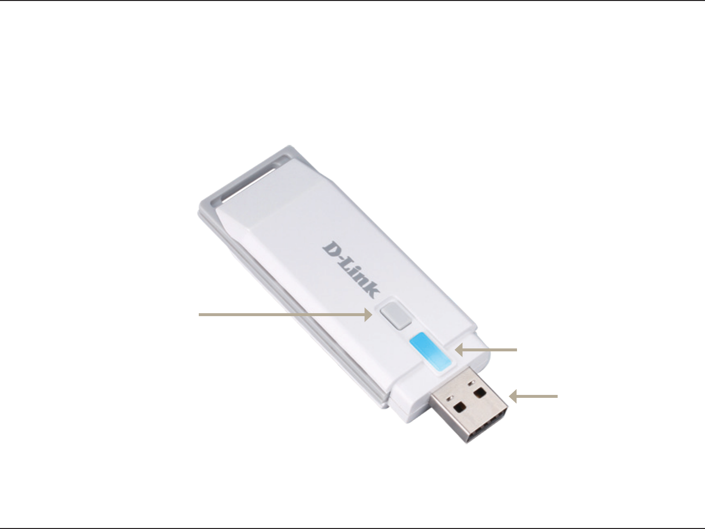
Product Overview

7D-Link DHM-101 User Manual
Product Overview
Set up your DHM-401T gateway. (Please refer to the DHM-401T user manual for more information.)
Plug the DHM-101 into an available USB port on the back of the DHM-401T gateway.
Press the pairing button on the back of the DHM-401T gateway until you hear a beep and the Online Status LED
ashes green. You now have 60 seconds to pair sensors to the gateway.
Press the pairing button on your Z-Wave device.
When you have successfully paired your device, the DHM-401T gateway will beep 2 times.
Press the unpairing button on the DHM-101 Z-Wave USB Dongle until you hear a beep and the Online Status LED
ashes green. You now have 60 seconds to unpair sensors from the gateway.
Press the program button on your Z-Wave device.
When you have successfully unpaired your device, the DHM-401T gateway will beep 2 times.

8D-Link DHM-101 User Manual
Appendix A - Technical Specications
Appendix A - Technical Specications
Interface: USB
Frequency: 908.42/908.40MHz
Transmission Range: 30 meters line of sight,
indoors
LED: Status LED
Button: Unpairing button
Dimensions: 87 x 28 x 12 mm
Operating Temperature: -15 to 85 °C
Humidity: 5% to 95% relative humidity, non-
condensing

Federal Communication Commission Interference Statement
This equipment has been tested and found to comply with the limits for a Class B
digital device, pursuant to Part 15 of the FCC Rules. These limits are designed to
provide reasonable protection against harmful interference in a residential installation.
This equipment generates, uses and can radiate radio frequency energy and, if not
installed and used in accordance with the instructions, may cause harmful interference
to radio communications. However, there is no guarantee that interference will not
occur in a particular installation. If this equipment does cause harmful interference
to radio or television reception, which can be determined by turning the equipment off
and on, the user is encouraged to try to correct the interference by one of the
following measures:
- Reorient or relocate the receiving antenna.
- Increase the separation between the equipment and receiver.
- Connect the equipment into an outlet on a circuit different from that to which the
receiver is connected.
- Consult the dealer or an experienced radio/TV technician for help.
FCC Caution: Any changes or modifications not expressly approved by the party
responsible for compliance could void the user's authority to operate this equipment.
This device complies with Part 15 of the FCC Rules. Operation is subject to the
following two conditions: (1) This device may not cause harmful interference, and (2)
this device must accept any interference received, including interference that may
cause undesired operation.
IMPORTANT NOTE:
This transmitter must not be co-located or operating in conjunction with any other
antenna or transmitter.
The availability of some specific channels and/or operational frequency bands are
country dependent and are firmware programmed at the factory to match the intended
destination. The firmware setting is not accessible by the end user.
--------------------------------------------------------------------------------------------------------
Industry Canada statement:
This device complies with RSS-210 of the Industry Canada Rules. Operation is
subject to the following two conditions:
(1) This device may not cause harmful interference, and (2) this device must accept
any interference received, including interference that may cause undesired operation.