D Link HM303TA1 Home Monitoring Wireless Door Contact User Manual
D Link Corporation Home Monitoring Wireless Door Contact
D Link >
User Manual

2D-Link DHM-901T User Manual
D-Link reserves the right to revise this publication and to make changes in the content hereof without obligation to
notify any person or organization of such revisions or changes.
D-Link and the D-Link logo are trademarks or registered trademarks of D-Link Corporation or its subsidiaries in the
United States or other countries. All other company or product names mentioned herein are trademarks or regis-
tered trademarks of their respective companies.
Copyright © 2010 by D-Link Systems, Inc.
All rights reserved. This publication may not be reproduced, in whole or in part, without prior expressed written per-
mission from D-Link Systems, Inc.
1.0 November 15, 2010 DHM-901T Revision A1 with rmware version 1.00

3D-Link DHM-901T User Manual
Package Contents ................................................... 4
System Requirements ............................................. 5
Features .................................................................. 6
Hardware Overview: Gateway (Front) ..................... 7
Hardware Overview: Gateway (Back) .....................8
Hardware Overview: Keypad ...................................9
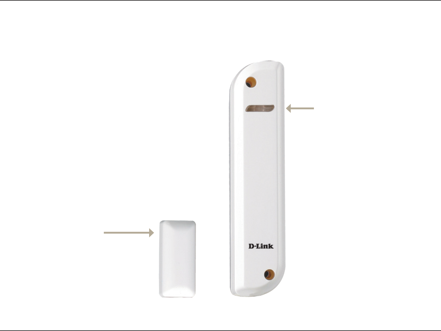
Hardware Overview: Contact Sensor .................... 10
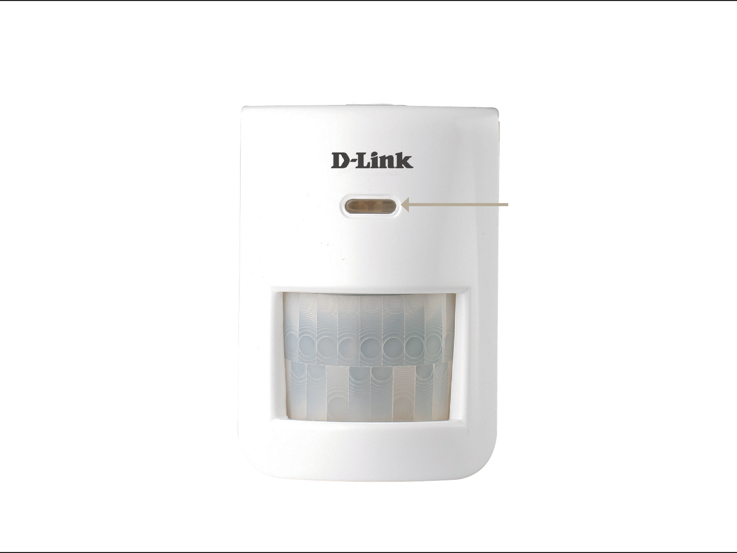
Hardware Overview: Motion Sensor ......................11
Hardware Installation: Gateway ............................. 12
Hardware Installation: Keypad ............................... 13
Hardware Installation: Contact Sensor .................. 14
Hardware Installation: Motion Sensor .................... 15
Technical Specications ........................................ 16

4D-Link DHM-901T User Manual
Product OverviewProduct Overview
If any of the above items are missing, please contact your reseller.
DHM-401T Gateway
DHM-301T Keypad
DHM-303T Contact Sensor
DHM-304T Motion Sensor
Stand for DHM-401T
Power adapter for DHM-401T
Bracket for DHM-304T
Batteries for DHM-301T/303T/304T
Mounting kits for DHM-301T/303T/304T
Ethernet cable
Quick Installation Guide

5D-Link DHM-901T User Manual
Product Overview
A computer with Windows XP SP2/Vista/7 or higher for conguration

6D-Link DHM-901T User Manual
Product Overview
The DHM-303T Contact Sensor can be used to detect whether a door or window is open or closed. You can use
this to provide security for windows, or to monitor entry and exit through a doorway, and can be used in tandem with
other sensors and keypads to monitor and control access to an area.
The DHM-304T Motion Sensor can be used to detect motion in an area. You can change the sensor's motion detec-
tion sensitivity to help you nd the right balance to detect movement without false alarms.
Each sensor and keypad periodically sends a "heartbeat" signal to the gateway, which noties you when the batter-
ies in a sensor need to be changed, or if a sensor is out of range.
The two USB ports allow you to expand your home monitoring system by adding adapters such as a DWM-156 3G
dongle for a 3G fallback Internet connection, or a DHM-101 Z-Wave USB Dongle to allow for connection to Z-Wave
devices.
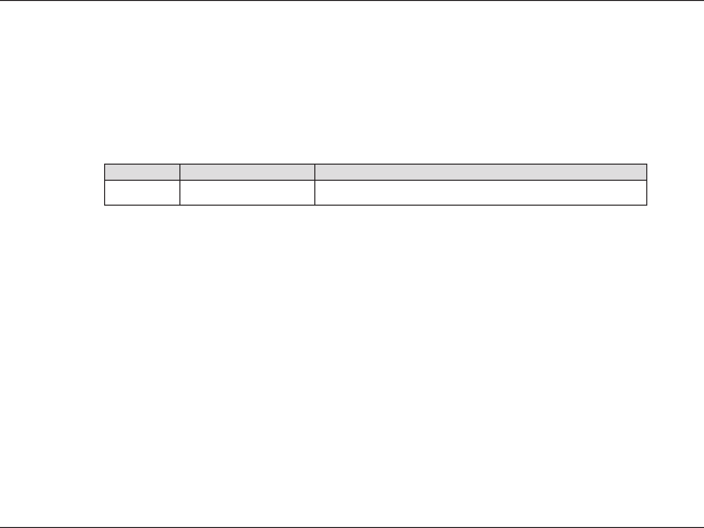
7D-Link DHM-901T User Manual
Product Overview
- Status
- Alarm
- Online
- Event
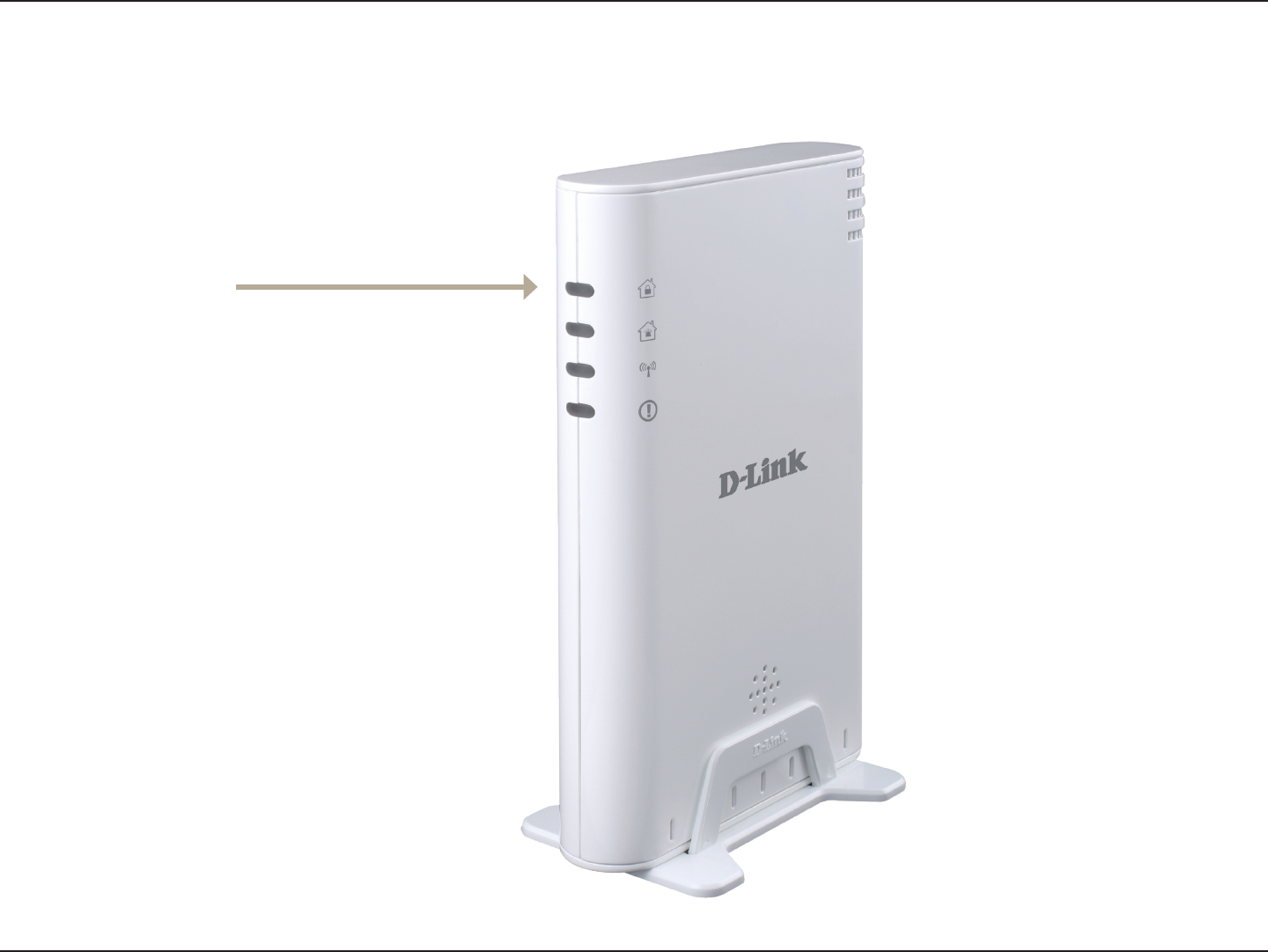
8D-Link DHM-901T User Manual
Product Overview
Connect to compatible USB devices, such
as the DHM-101 Z-Wave USB Dongle.
Connects to your router.
Turns on pairing mode.
Connects to the included power
adapter.
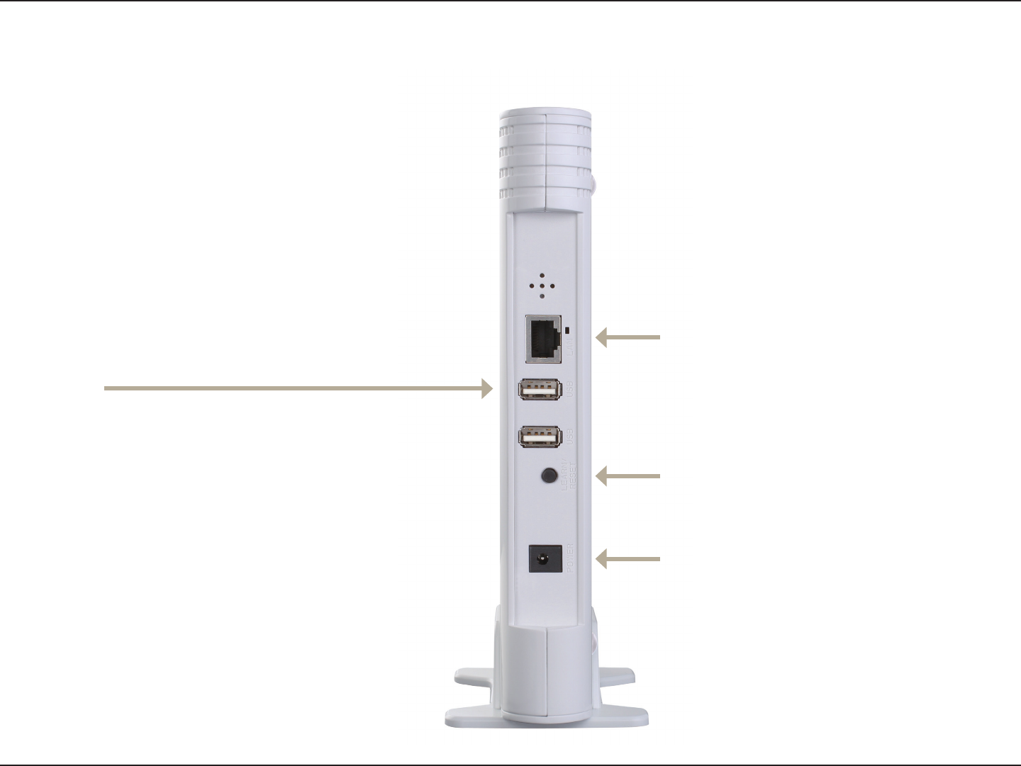
9D-Link DHM-901T User Manual
Product Overview
- Active/Operation
- Status
- Alarm/Error
10D-Link DHM-901T User Manual
Product Overview
11D-Link DHM-901T User Manual
Product Overview

12D-Link DHM-901T User Manual
Product Overview
Remove the battery cover and insert 6 AAA batteries (not included) as indicated.
Replace the battery cover.
Connect one end of the included Ethernet cable to an available LAN port on your router, and connect the other
end to the WAN port on the DHM-401T.
Connect the power adapter to the DHM-401T.

13D-Link DHM-901T User Manual
Product Overview
Slide and remove the battery cover on the back of the keypad, then insert 2 AAA batteries as indicated.
Replace the battery cover.
Press and hold the pairing button on the DHM-401T Gateway until you hear a beep and the Online Status LED
ashes green. You now have 60 seconds to pair sensors to the gateway.
Press and hold the 1 and 2 buttons on the DHM-301T Keypad at the same time.
When the 2 devices have successfully paired, the DHM-401T gateway will beep 2 times, and the DHM-301T Key-
pad will beep 4 times.
You can hang the keypad 2 different ways.
You can push in and slide the D-Link logo up to uncover 2 screw holes you can use to mount the keypad to a wall
using the included screws.
Alternatively, you can insert the included screws into a wall, then use the mounting holes on the back of the key-
pad to hang it on the screws.

14D-Link DHM-901T User Manual
Product Overview
Use a coin to open the case, then lift the top cover off of the contact sensor.
Insert the CR123A 3V battery as indicated.
Replace the top cover of the contact sensor and make sure the two halves snap together.
Press and hold the pairing button on the DHM-401T Gateway until you hear a beep and the Online Status LED
ashes green. You now have 60 seconds to pair sensors to the gateway.
Press the pairing button on the front of the DHM-303T Contact Sensor. The LED will turn on.
When the 2 devices have successfully paired, the DHM-401T gateway will beep 2 times, and the LED on the
DHM-303T Contact Sensor will ash for 2 seconds.
Make sure your door or window is closed, then use one of the included adhesive strips from the included DHM-
303T mounting kit to attach the contact sensor piece to the edge of your door or window.
Put the screws from the included DHM-303T mounting kit through the two holes at the top and bottom of the main
contact sensor and mount it to your door frame or window frame next to the contact sensor piece.
Make sure that the main contact sensor and the contact sensor piece are aligned to that the small ridge on both
parts are next to each other when your door or window is closed. The main contact sensor's LED will ash when
the contact sensor piece is moved next to or away from it.

15D-Link DHM-901T User Manual
Product Overview
Slide and remove the battery cover on the top of the Motion Sensor, then insert 2 AAA batteries as indicated.
Replace the battery cover.
Press and hold the pairing button on the DHM-401T Gateway until you hear a beep and the Online Status LED
ashes green. You now have 60 seconds to pair sensors to the gateway.
Press the pairing button on front of the DHM-304T Motion Sensor. The LED will turn on.
When the 2 devices have successfully paired, the DHM-401T gateway will beep 2 times, and the LED on the
DHM-304T Motion Sensor will ash for 2 seconds.
Put the screw from the included DHM-304T mounting kit through the hole in the DHM-304T bracket and mount it
to a wall. Alternatively, you can use the adhesive strip from the included DHM-303T mounting kit to mount it to a
wall.
Push the ball on the DHM-304T bracket into the socket on the back of the DHM-304T Motion Sensor until it snaps
into place. You can then adjust the angle and position of the Motion Sensor as you wish.

16D-Link DHM-901T User Manual
Appendix A - Technical Specications
Appendix A - Technical Specications
315 MHz
-10 to 50 °C (14 to 122 °F), Indoor use
5% - 95% RH non-condensing
Transmission Range: Minimum 70 meters in open
air
Audio: 1 x Buzzer, 1 x Siren
Siren Volume: 85 db
USB: 2 x USB 2.0 compliant ports for compatible
3G dongles, Zigbee dongles, or Z-Wave dongles
Power: External power adapter, 100-120 V
50 / 60 Hz input, 12 V / 2 A output, 6 x AAA battery
for backup power
Backup Battery Life: 50 minutes with alkaline
batteries
LEDs: Status, Alarm, Online, Event
Dimensions: 206 x 133 x 31.5 mm
Transmission Range: Minimum 70 meters in free
space
Power: 2 x AAA batteries
Battery Life: 1 year with alkaline batteries
LEDs: Active/Operation, Status, Alarm/Error
Dimensions: 90 x 66 x 21.6 mm
Break Distance: >28mm
Make Distance: <18mm
Transmission Range: Minimum 70 metres in free
space
Power: 1 x CR-123A 3V lithium battery
Battery Life: 3 years with alkaline battery
LED: Pairing/Status
Dimensions: 90 x 22 x 21.3 mm
Detection Coverage: 7 meters (at 20°C)
Detection Angle: 90 degrees
Transmission Range: Minimum 70 metres in free
space
Power: 2 x AAA batteries
Battery Life: 1 year with alkaline batteries
LED: Pairing/Status
Dimensions: 83 x 58 x 40.5 mm

Federal Communication Commission Interference Statement
This equipment has been tested and found to comply with the limits for a Class B
digital device, pursuant to Part 15 of the FCC Rules. These limits are designed to
provide reasonable protection against harmful interference in a residential installation.
This equipment generates, uses and can radiate radio frequency energy and, if not
installed and used in accordance with the instructions, may cause harmful interference
to radio communications. However, there is no guarantee that interference will not
occur in a particular installation. If this equipment does cause harmful interference
to radio or television reception, which can be determined by turning the equipment off
and on, the user is encouraged to try to correct the interference by one of the
following measures:
- Reorient or relocate the receiving antenna.
- Increase the separation between the equipment and receiver.
- Connect the equipment into an outlet on a circuit different from that to which the
receiver is connected.
- Consult the dealer or an experienced radio/TV technician for help.
FCC Caution: Any changes or modifications not expressly approved by the party
responsible for compliance could void the user's authority to operate this equipment.
This device complies with Part 15 of the FCC Rules. Operation is subject to the
following two conditions: (1) This device may not cause harmful interference, and (2)
this device must accept any interference received, including interference that may
cause undesired operation.
IMPORTANT NOTE:
This transmitter must not be co-located or operating in conjunction with any other
antenna or transmitter.
The availability of some specific channels and/or operational frequency bands are
country dependent and are firmware programmed at the factory to match the intended
destination. The firmware setting is not accessible by the end user.
--------------------------------------------------------------------------------------------------------
Industry Canada statement:
This device complies with RSS-210 of the Industry Canada Rules. Operation is
subject to the following two conditions:
(1) This device may not cause harmful interference, and (2) this device must accept
any interference received, including interference that may cause undesired operation.