D Link SL2640T DIGITAL TRANSMISSION SYSTEM User Manual users manual
D Link Corporation DIGITAL TRANSMISSION SYSTEM users manual
D Link >
users manual
Before You Begin
Make sure you have all the necessary information and equipment on hand before beginning the
installation.
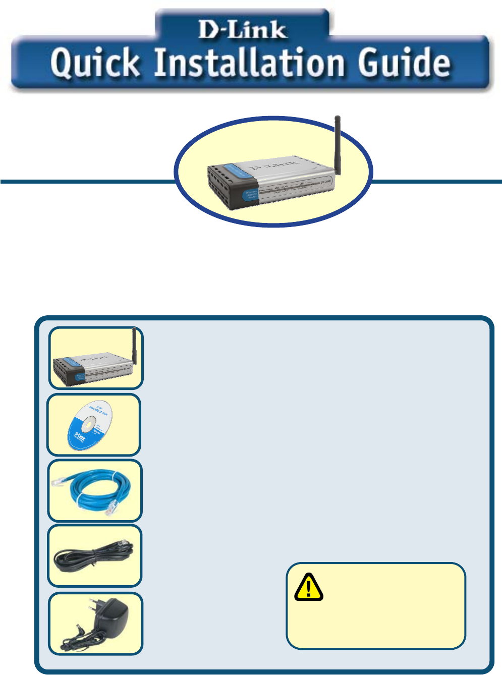
Check Your Package Contents
If any of the items above are missing, please contact your reseller.
This product can be se
t
up using any current we
b
b
rowser, e.g., Interne
t
Explorer 6 or Netscape
N
avigator 6.2.3.
Using a power supply
with a different voltage
rating will damage and void
the warranty for this product.
DSL-2640T Wireless ADSL Router
CD-ROM (containing Manual)
Ethernet (CAT5 UTP) Cable
Telephone Cable
Power Adapter
2
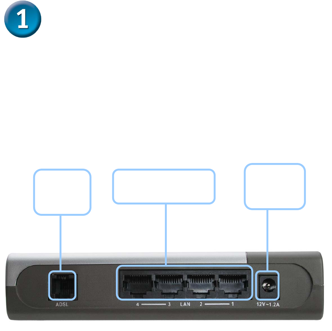
Connecting the Router to Your Computer
A. First, connect the power adapter to the receptor at the back panel of the
DSL-2640T and then plug the other end of the power adapter to a wall outlet or
power strip. The Power LED will turn on to indicate proper operation.
B. Insert one end of the cable into the Ethernet port on the back panel of the
DSL-2640T and the other end of the cable to an Ethernet Adapter or available
Ethernet port on your computer.
ADSL Port
Connect to
ADSL line
Ethernet Ports
Connect to Ethernet cable
Power Input
Connect to
power adapter
3
Configuring the Router
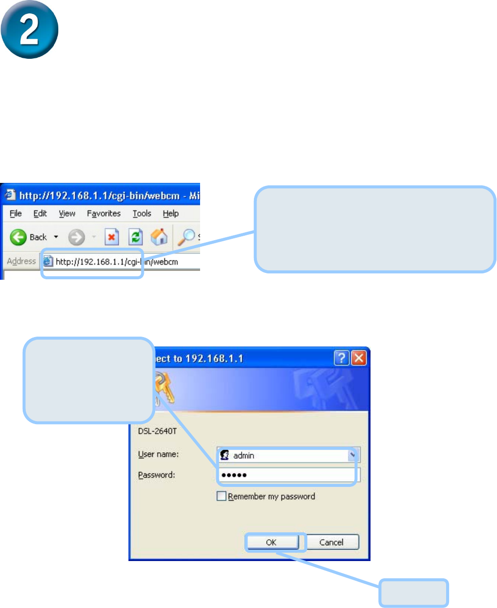
To use your Web browser to access the web pages used to set up the Router, your computer
must be configured to “Obtain an IP address automatically,” that is, you must change the IP
network settings of your computer so that it is a DHCP Client. If you are using Windows XP
and do not know how to change your network settings, skip ahead to Appendix A and read the
instructions provided. You may also read the User Manual for instructions on changing IP
settings for computers running Windows operating systems.
The logon pop-up screen will appear.
Open your Web browser and type
“http://192.168.1.1” into the URL address
box. Then press the Enter or Return key.
The login dialog appears.
Type “admin” for the
User Name and
“admin” in the
Password field.
Click OK.
4
Configuring the Router (continued)
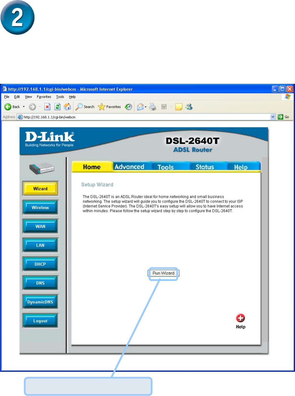
Once you have logged in, the Home directory tab featuring the Setup Wizard window opens.
Most users will be able to use the Setup Wizard to establish the ADSL connection to your ISP.
To begin using the Setup Wizard, click on the Run Wizard button in the middle of the web page.
The first pop-up Setup Wizard window opens.
Click on the Run Wizard button.
5
Configuring the Router (continued)
The Setup Wizard procedure consists of these general steps:
1. Set the time zone
2. Set the Internet connection
3. Set the Wireless configuration
4. Restart the Router
When you setup the Internet connection, you will need to enter information provided by your ISP.
If you have not been given information about the connection type, the VPI and VCI numbers, as
well as other information related to the connection type, you will not be able to complete the
setup.
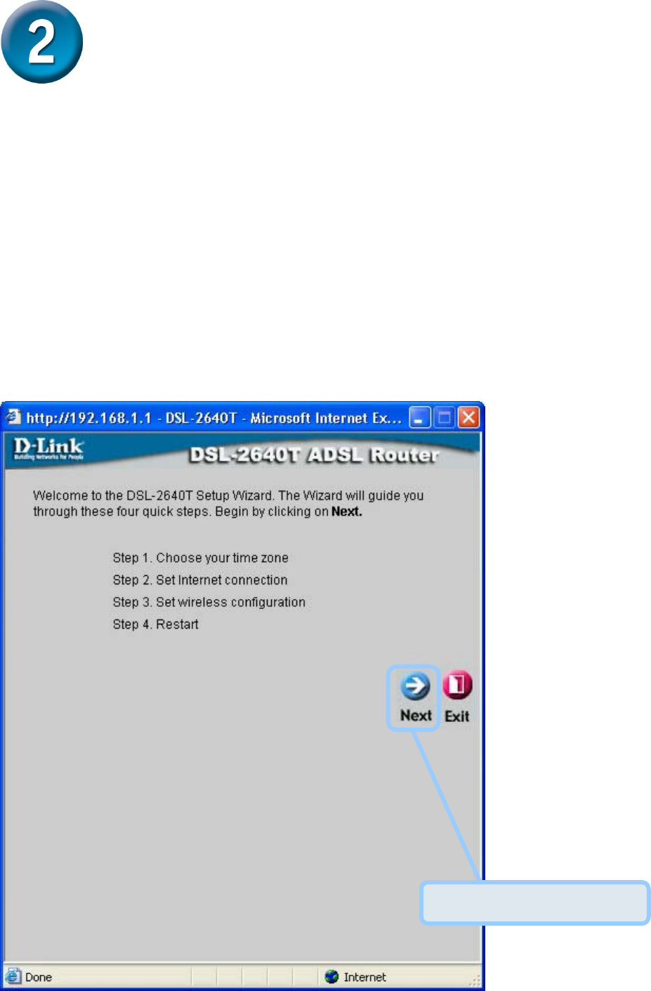
The first Setup Wizard window lists a summary of the steps required to complete the setup.
Click the Next button to begin setup.
Click the Next button.
6
Configuring the Router (continued)
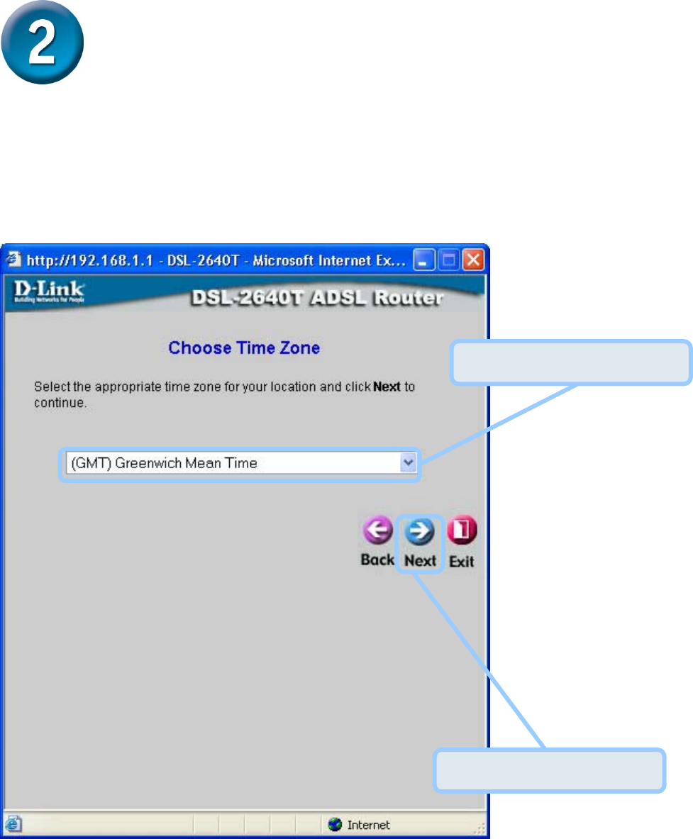
The initial step is to configure the Time Zone used for the Router’s system clock.
Select the appropriate time zone for your location. Click the Next button when you have
made your choice.
Select the Time Zone.
Click the Next button.
7
Configuring the Router (continued)
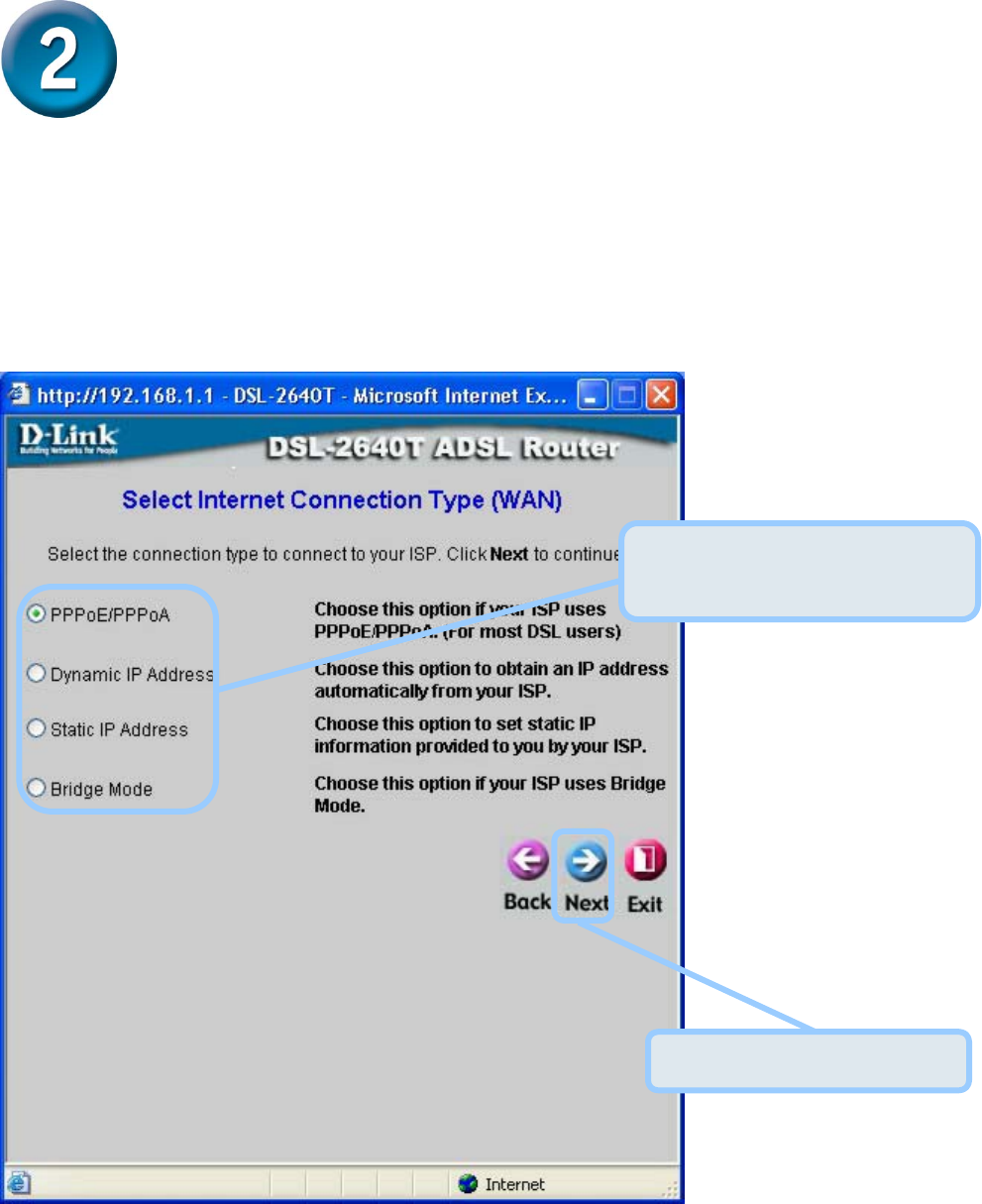
Next you will Select the Internet Connection Type for the WAN interface. Your ISP has given
this information to you. If you do not know what type of connection to use, exit the Setup Wizard
and contact your ISP for the information. The Setup Wizard window that appears when you click
the Next button depends on what connection type you select. The connection types available in
the Setup Wizard window are PPPoE/PPPoA , Dynamic IP Address, Static IP Address, and
Bridge Mode. Follow the instructions below for the type of connection you are using.
Select the Connection Type
used for your ADSL service.
Click the Next button.
8
Configuring the Router (continued)
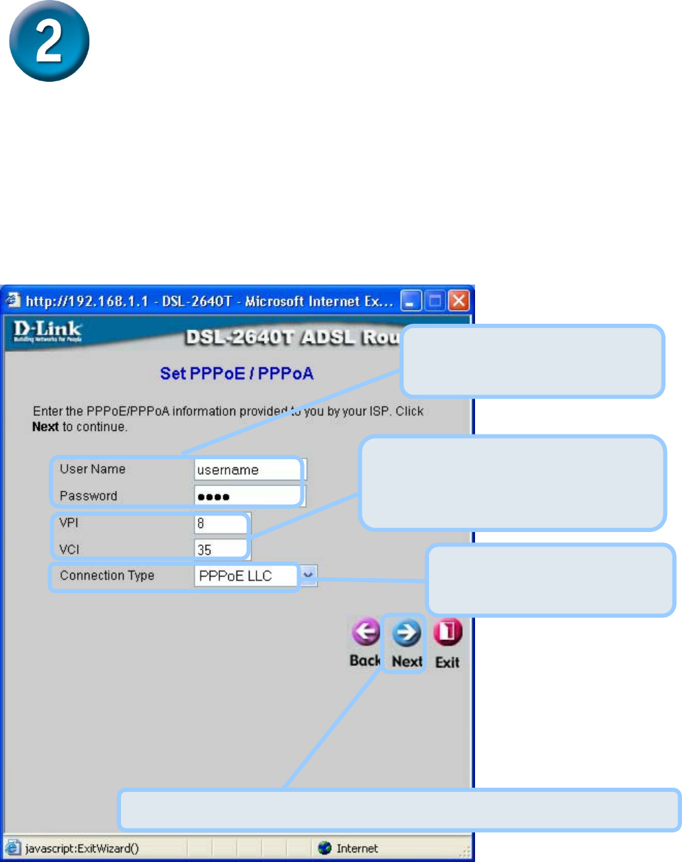
PPPoE/PPPoA Connections
If you selected the PPPoE/PPPoA connection type in the previous window, you will see the
Setup Wizard window pictured here. Type in the Username and Password used to identify and
verify your account to the ISP. If you have been instructed to change the VPI number and VCI
number, type in the new values. Select the Connection Type used for encapsulation specific to
your service. Click Next when you are ready to continue to the Setup Completed window.
Type the User Name and
Password for your ISP account.
Change the VPI and VCI numbers as
instructed by your ISP. Type the new
values in the spaces provided here.
Select the Connection Type
as instructed by your ISP.
Click the Next button. Skip ahead to the Setup Completed window below.
9
Configuring the Router (continued)
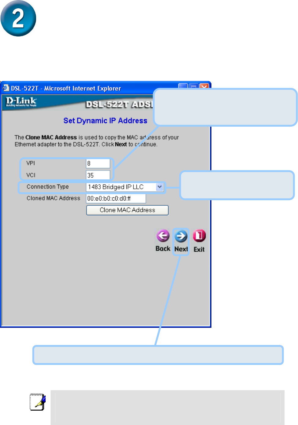
Dynamic IP Address Connections
If you selected the Dynamic IP Address connection type, select the Connection Type used for
encapsulation. If you have been instructed to change the VPI number and VCI number, type in
the new values. Click Next when you are ready to continue the Setup Completed window.
Note
An option for Dynamic IP Address connections is to use the MAC address from your computer in
place of the Router’s actual MAC address for the purpose of Address Resolution by the ISP’s
DHCP server. To implement this feature click on the Clone MAC Address button before
continuing to the next window.
Change the VPI and VCI numbers as
instructed by your ISP. Type the new
values in the spaces provided here.
Select the Connection Type as
instructed by your ISP.
Click the Next button. Skip ahead to the Setup Completed window below.
10
Configuring the Router (continued)
Static IP Address Connections
If you selected the Static IP Address connection type, change the WAN IP Address, Subnet
Mask, ISP Gateway Address, Primary DNS (Server IP) Address and (if available) Secondary
DNS (Server IP) Address as instructed by your ISP. Select the Connection Type used for
encapsulation. If you have been instructed to change the VPI number and VCI number, type in
the new values. Click Next when you are ready to continue to the Setup Completed window.
Select the Connection Type
as instructed by your ISP.
Change the VPI and VCI numbers as
instructed by your ISP. Type the new
values in the spaces provided here.
Type the IP addresses for the
WAN IP Address, WAN Subnet
Mask, ISP Gateway Address,
Primary DNS Address and
Secondary DNS Address.
Click the Next button. Skip ahead to the Setup Completed window below.
11
Configuring the Router (continued)
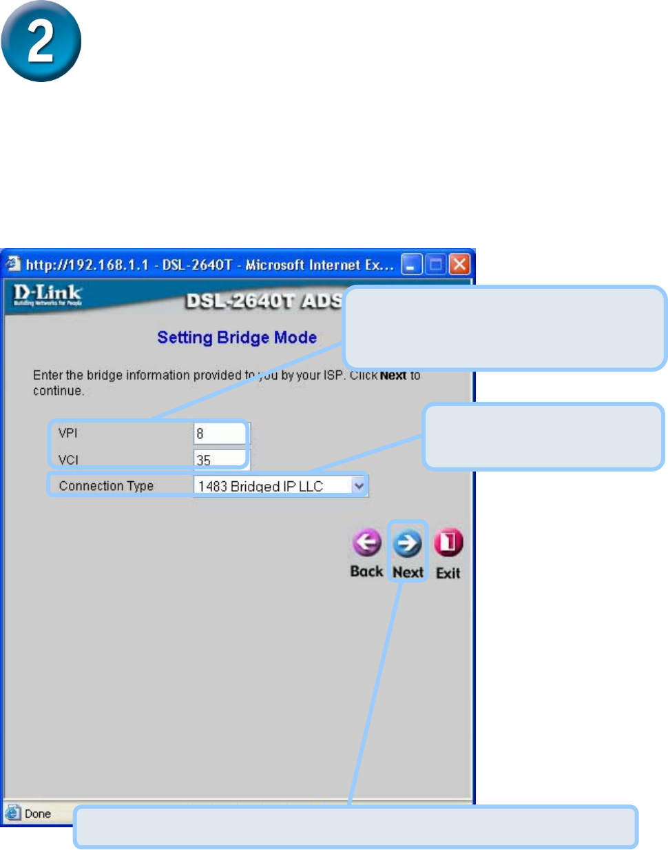
Bridge Connections
If you selected the Bridge connection type, select the Connection Type used for encapsulation.
If you have been instructed to change the VPI number and VCI number, type in the new values.
Click Next when you are ready to continue to the Setup Completed window.
Select the Connection Type
as instructed by your ISP.
Click the Next button. Skip ahead to the Setup Completed window below.
Change the VPI and VCI numbers as
instructed by your ISP. Type the new
values in the spaces provided here.
12
Configuring the Router (continued)
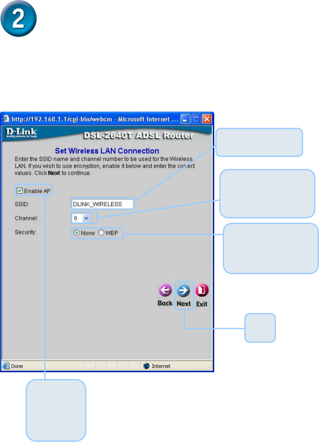
Wireless LAN Configuration
Configure the SSID and Channel for the Wireless LAN. You may also configure WEP security
settings at this time or configure them later using the web manager. Select None to configure
WEP later. To disable the wireless access point, click the Enable AP option box to remove the
green check mark.
Enter the SSID for the
Wireless LAN
Choose the wireless
Channel to be used for
your WLAN from the pull
down menu.
Click
Next
Choose the wireless
security setup. If WEP is
used an additional step is
required for configuration
To disable the
access point,
click to
remove the
check mark
13
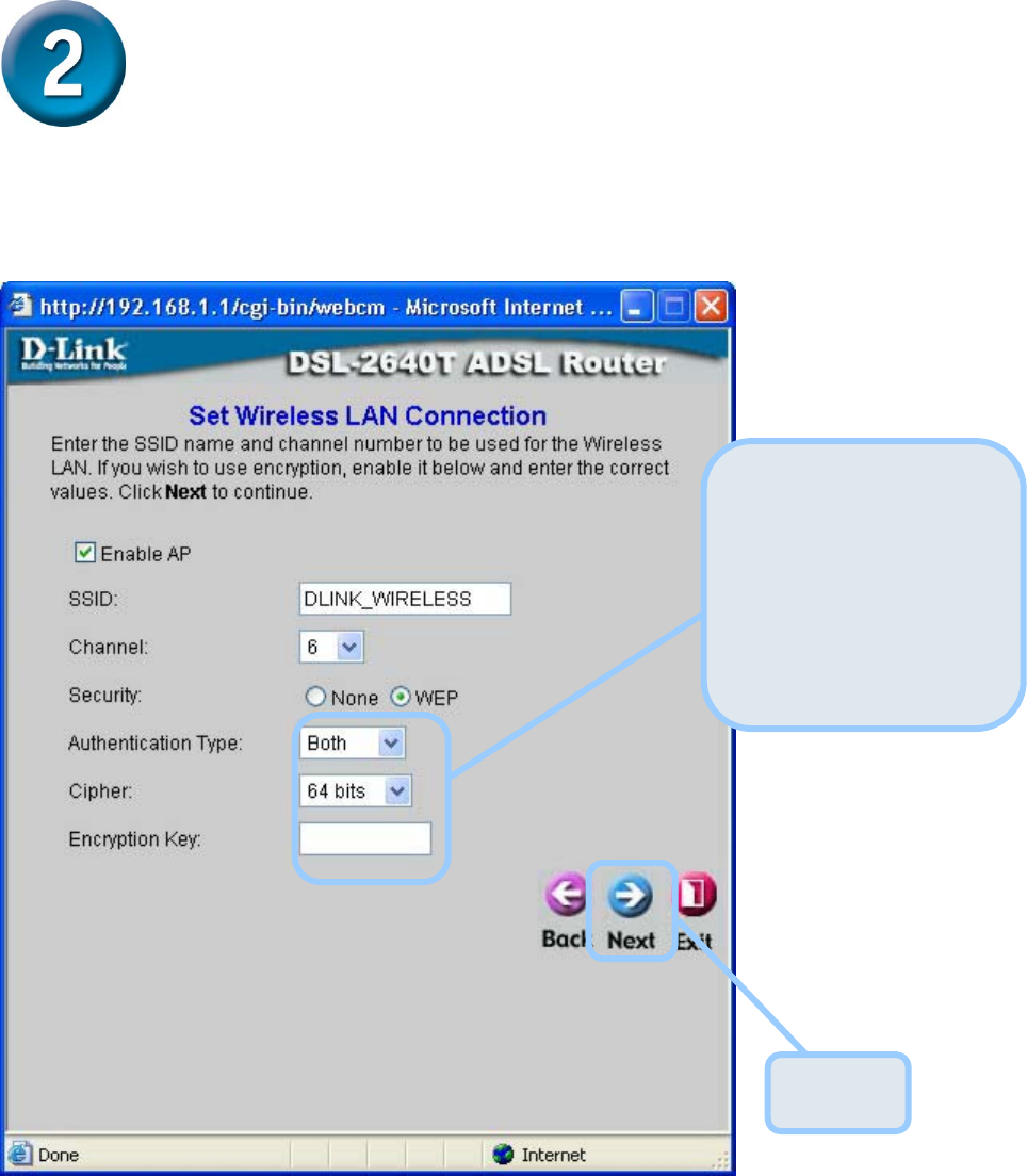
Configuring the Router (continued)
WEP Configuration
If you are configuring WEP security, select the Authentication Type, Cipher rate and
Encryption Key. Click Next to continue to the final menu.
14
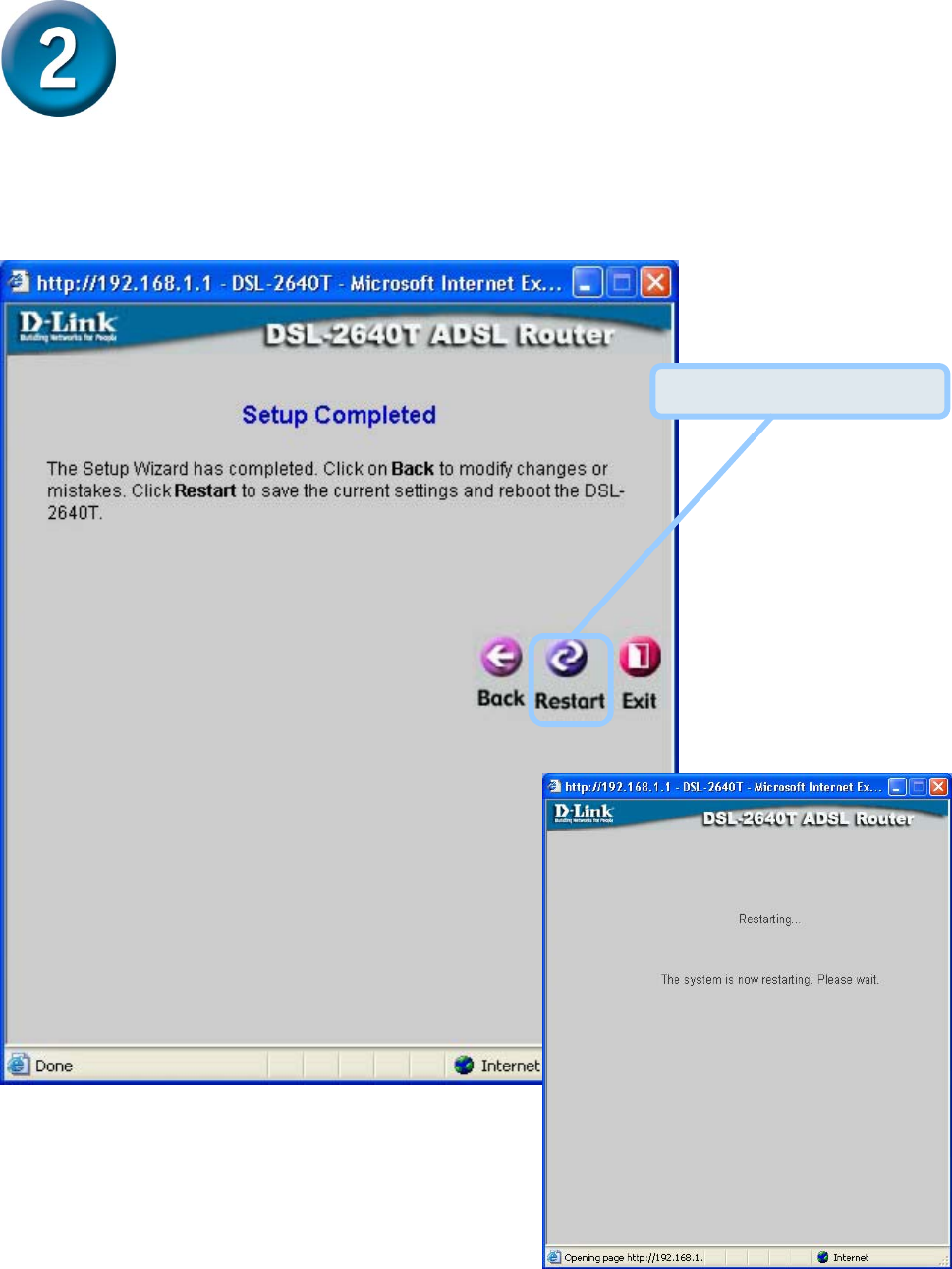
Configuring the Router (continued)
Setup Completed
All the settings for the ADSL connection are now completed. Click the Restart button to save
the new settings and restart the Router. It will take about two minutes to restart the Router.
The window pictured on the right appears
during the save and restart process.
Please do not turn off the Router while
it is still displayed!
Click the Restart button.
15
Appendix
For additional settings or information, refer to the Advanced, Tools, or Status tabs on the Web
Management interface; or to the manual located on the CD-ROM.
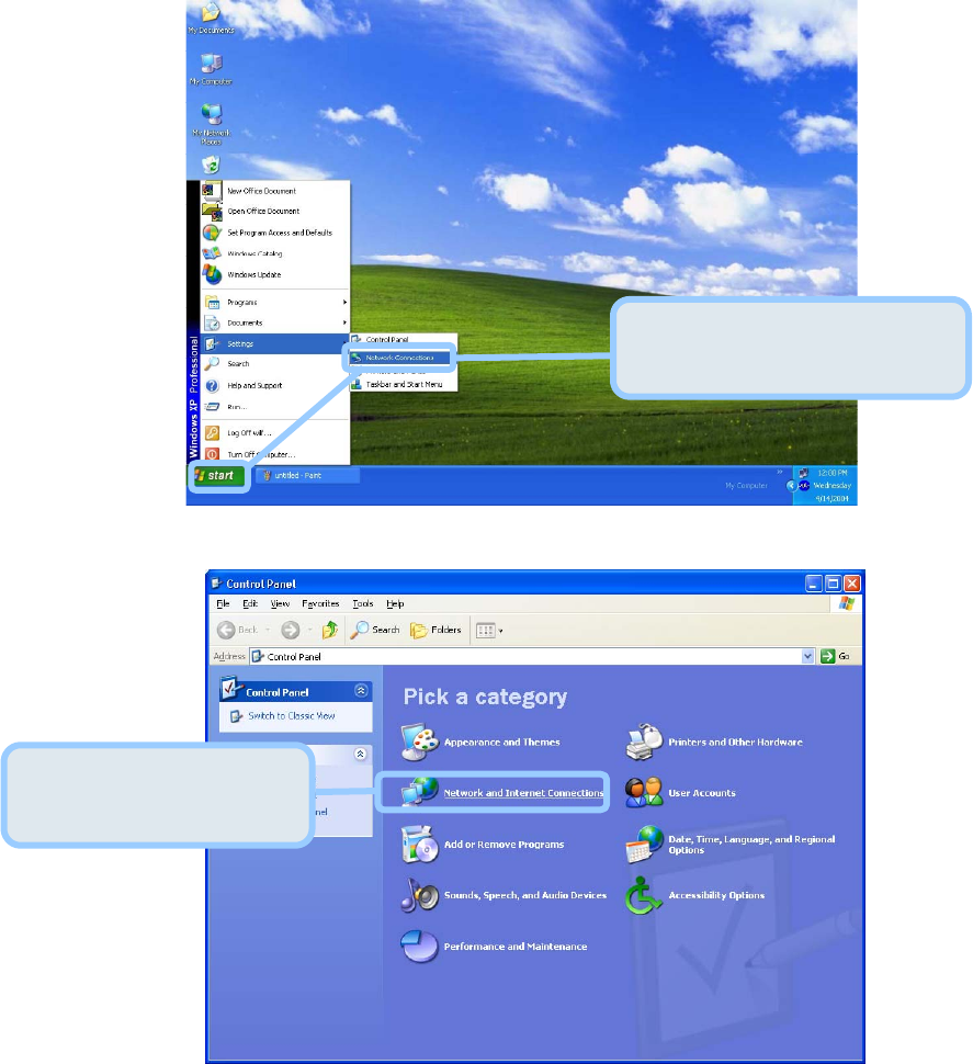
Configuring IP Settings in Windows XP
Use the following steps to configure a computer running Windows XP to be a DHCP client.
1. From the Start menu on your desktop, go to Control Panel.
2. In the Control Panel window, click Network and Internet Connections.
Click Network and
Internet Connections.
From the Start menu, go to
Control Panel.
16
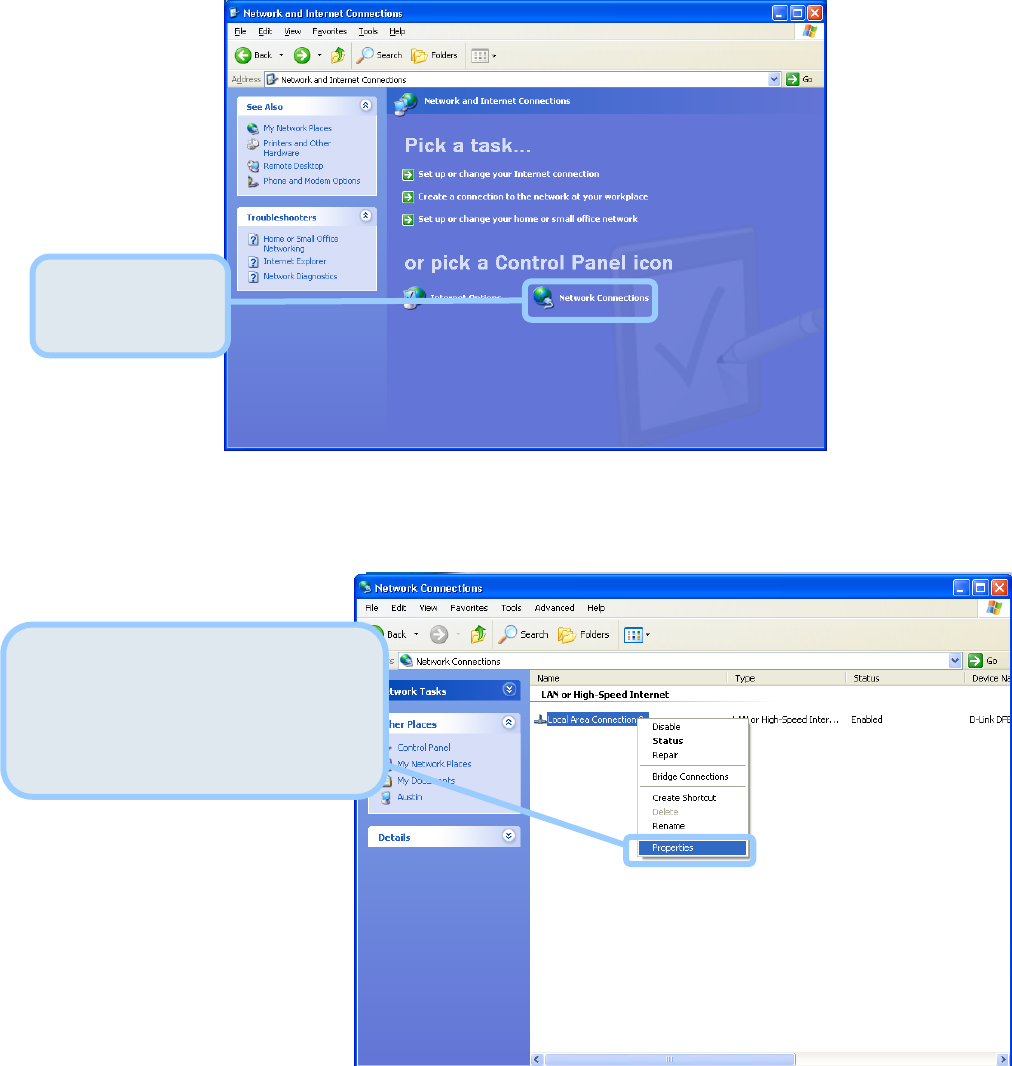
3. In the Network and Internet Connections window, click Network Connections.
4. In the Network Connections window, right-click on Local Area Connection, then click
Properties.
Right-click on the Local Area
Connection icon and select the
Properties option from the
pull-down menu.
Click Network
Connections.
17
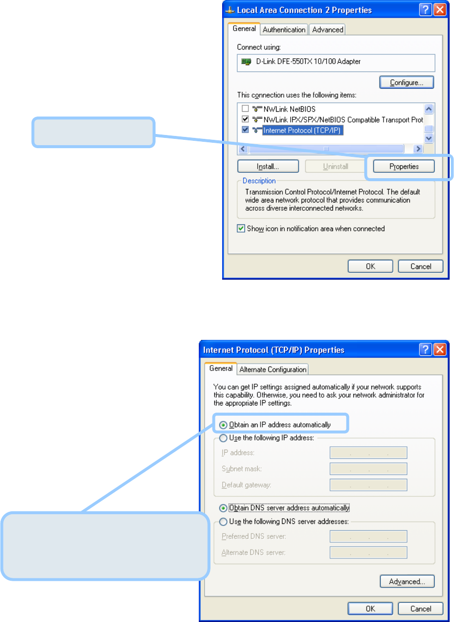
5. In the General tab of the Local Area Connection Properties window, highlight Internet
Protocol (TCP/IP) under “This connection uses the following items:” by clicking on it
once. Click on the Properties button.
6. Select “Obtain an IP address automatically” by clicking once in the circle. Click the OK
button.
Your computer is now ready to use the Router’s DHCP server.
Click Properties.
Select Obtain an IP address
automatically in the Internet
Protocol (TCP/IP) Properties window

18

19
Technische Unterstützung
Aktualisierte Versionen von Software und Benutzerhandbuch finden
Sie auf der Website von D-Link.
D-Link bietet kostenfreie technische Unterstützung für Kunden
innerhalb Deutschlands, Österreichs, der Schweiz und Osteuropas.
Unsere Kunden können technische Unterstützung über unsere
Website, per E-Mail oder telefonisch anfordern.
Web: http://www.dlink.de
E-Mail: support@dlink.de
Telefon: +49 (1805)2787
0,12€/Min aus dem Festnetz der Deutschen Telekom.
Telefonische technische Unterstützung erhalten Sie Montags bis Freitags
von 09.00 bis 17.30 Uhr.
Wenn Sie Kunde von D-Link außerhalb Deutschlands, Österreichs, der
Schweiz und Osteuropas sind, wenden Sie sich bitte an die zuständige
Niederlassung aus der
Liste im Benutzerhandbuc
h

20
Assistance technique
Vous trouverez la documentation et les logiciels les plus récents sur le
site web D-Link.
Ceux-ci peuvent contacter le service technique de
D-Link par notre site internet ou par téléphone.
Support technique destiné aux clients établis en France:
Assistance technique D-Link par téléphone :
0 820 0803 03
Assistance technique D-Link sur internet :
http://www.dlink.fr
e-mail : support@dlink.fr
Support technique destiné aux clients établis au Canada :
Assistance technique D-Link par téléphone :
(800) 361-5265
Lun.-Ven. 7h30 à 21h00 HNE.
Assistance technique D-Link sur internet :
http ://support.dlink.ca
e-mail : support@dlink.ca

21
Asistencia Técnica
Puede encontrar el software más reciente y
documentación para el usuario en el sitio web de
D-Link . D-Link ofrece asistencia técnica gratuita para
clientes dentro de España durante el periodo de garantía
del producto. Los clientes españoles pueden ponerse en
contacto con la asistencia técnica de D-Link a través de
nuestro sitio web o por teléfono.
Asistencia Técnica de D-Link por teléfono:
902 304545
de lunes a viernes desde las 9:00 hasta las14:00 y de las
15:00 hasta las 18:00
Asistencia Técnica de D-Link a través de Internet:
http://www.dlink.es
email: soporte@dlink.es

22
Supporto tecnico
Gli ultimi aggiornamenti e la documentazione sono
disponibili sul sito D-Link.
Supporto tecnico per i clienti residenti in Italia
D-Link Mediterraneo S.r.L.
Via N. Bonnet 6/B 20154 Milano
Supporto Tecnico dal lunedì al venerdì dalle ore
9.00 alle ore 19.00 con orario continuato
Telefono: 02-39607160
URL : http://www.dlink.it/supporto.html
Email: tech@dlink.it

23
Technical Support
You can find software updates and user documentation on the D-Link website.
D-Link provides free technical support for customers within Benelux for the
duration of the warranty period on this product.
Benelux customers can contact D-Link technical support through our website, o
r
by phone.
Tech Support for customers within the Netherlands:
D-Link Technical Support over the Telephone:
0900 501 2007
Monday to Friday 8:00 am to 10:00 pm
D-Link Technical Support over the Internet:
www.dlink.nl
Tech Support for customers within Belgium:
D-Link Technical Support over the Telephone:
+32(0)2 717 3248
Monday to Friday 8:00 am to 10:00 pm
D-Link Technical Support over the Internet:
www.dlink.be

24
Pomoc techniczna
Najnowsze wersje oprogramowania i dokumentacji użytkownika
można znaleźć w serwisie internetowym firmy D-Link.
D-Link zapewnia bezpłatną pomoc techniczną klientom w Polsce
w okresie gwarancyjnym produktu.
Klienci z Polski mogą się kontaktować z działem pomocy
technicznej firmy D-Link za pośrednictwem Internetu lub
telefonicznie.
Telefoniczna pomoc techniczna firmy D-Link:
+49 (1805)-2787
Pomoc techniczna firmy D-Link świadczona przez
Internet:
URL: http://www.dlink.pl
e-mail: pomoc_techniczna@dlink.de

25
Technická podpora
Aktualizované verze software a uživatelských příruček najdete na
webové stránce firmy D-Link.
D-Link poskytuje svým zákazníkům bezplatnou technickou
podporu
Zákazníci mohou kontaktovat oddělení technické podpory přes
webové stránky, mailem nebo telefonicky
Web: http://www.dlink.de
E-Mail: support@dlink.de
Telefon: +49 (1805)-2787
Telefonická podpora je v provozu:
PO-ČT od 08.00 do 19.00
PÁ od 08.00 do 17.00
26
Technikai Támogatás
Meghajtó programokat és frissítéseket a D-Link Magyarország
weblapjáról tölthet le.
Telefonon technikai segítséget munkanapokon hétfőtől-csütörtökig
9.00 – 16.00 óráig és pénteken 9.00 – 14.00 óráig kérhet
a (1) 461-3001 telefonszámon vagy a support@dlink.hu
emailcímen.
Magyarországi technikai támogatás :
D-Link Magyarország
1074 Budapest, Alsóerdősor u. 6. – R70 Irodaház 1 em.

27
Teknisk Support
Du kan finne programvare oppdateringer og bruker
dokumentasjon på D-Links web sider.
D-Link tilbyr sine kunder gratis teknisk support under
produktets garantitid.
Kunder kan kontakte D-Links teknisk support via våre
hjemmesider, eller på tlf.
Teknisk Support:
D-Link Teknisk telefon Support:
800 10 610
(Hverdager 08:00-20:00)
D-Link Teknisk Support over Internett:
http://www.dlink.no

28
Teknisk Support
Du finder software opdateringer og bruger-
dokumentation på D-Link’s hjemmeside.
D-Link tilbyder gratis teknisk support til kunder
i Danmark i hele produktets garantiperiode.
Danske kunder kan kontakte D-Link’s tekniske
support via vores hjemmeside eller telefonisk.
D-Link teknisk support over telefonen:
Tlf. 7026 9040
Åbningstider: kl. 08:00 – 20:00
D-Link teknisk support på Internettet:
http://www.dlink.dk

29
Teknistä tukea asiakkaille
Suomessa:
D-Link tarjoaa teknistä tukea asiakkailleen.
Tuotteen takuun voimassaoloajan.
Tekninen tuki palvelee seuraavasti:
Arkisin klo. 9 - 21
numerosta
0800-114 677
Internetin kautta
Ajurit ja lisätietoja tuotteista.
http://www.dlink.fi
Sähköpostin kautta
voit myös tehdä kyselyitä.

30
Teknisk Support
På vår hemsida kan du hitta mer information om mjukvaru
uppdateringar och annan användarinformation.
D-Link tillhandahåller teknisk support till kunder i Sverige
under hela garantitiden för denna produkt.
Teknisk Support för kunder i Sverige:
D-Link Teknisk Support via telefon:
0770-33 00 35
Vardagar 08.00-20.00
D-Link Teknisk Support via Internet:
htt
p
://www.dlink.se

31
(15.21)
Warning: Changes or modifications to this unit not expressly approved by the party
responsible for compliance could void the user authority to operate the equipment.
15.19 (a)(3)
This device complies with Part 15 of the FCC Rules. Operation is subject to the
following two conditions: (1) this device may not cause harmful interference, and (2) this
device must accept any interference received, including interference that may cause
undesired operation.
The users manual or instruction manual for an intentional or unintentional radiator
shall caution the user that changes or modifications not expressly approved by the party
responsible for compliance could void the user’s authority to operate the equipment.
CAUTION:
To comply with FCC RF exposure compliance requirements, a separation distance of at
least 20 cm must be maintained between the antenna of this device and all persons.
Repair Center: For FCC Part 68、Part15 in USA/美國當地代表
Company Name: D-Link corp.
Tel: (714) 885-6000
Contact Person: Michael Hsu /Title: P.Manager
Email: mhsu@dlink.com
Address: 17595 Mt. Herrmann Street Fountain Valley, CA 92708 U.S.A