D Link SL2740EA1 Wireless N300 ADSL2+Modem Router User Manual ADSL Four Ports USB Router
D Link Corporation Wireless N300 ADSL2+Modem Router ADSL Four Ports USB Router
D Link >
User Manual.pdf
DSL-2740E
User Manual v1.00
Federal Communication Commission Interference Statement
This device complies with Part 15 of the FCC Rules. Operation is subject to the following two conditions: (1) This device may not cause harmful interference, and (2) this device must
accept any interference received, including interference that may cause undesired operation.
This equipment has been tested and found to comply with the limits for a Class B digital device, pursuant to Part 15 of the FCC Rules. These limits are designed to provide reasonable
protection against harmful interference in a residential installation. This equipment generates, uses and can radiate radio frequency energy and, if not installed and used in accordance with
the instructions, may cause harmful interference to radio communications. However, there is no guarantee that interference will not occur in a particular installation. If this equipment
does cause harmful interference to radio or television reception, which can be determined by turning the equipment off and on, the user is encouraged to try to correct the interference by
one of the following measures:
- Reorient or relocate the receiving antenna.
- Increase the separation between the equipment and receiver.
- Connect the equipment into an outlet on a circuit different from that
to which the receiver is connected.
- Consult the dealer or an experienced radio/TV technician for help.
FCC Caution: Any changes or modifications not expressly approved by the party responsible for compliance could void the user's authority to operate this equipment.
This transmitter must not be co-located or operating in conjunction with any other antenna or transmitter.
Radiation Exposure Statement:
This equipment complies with FCC radiation exposure limits set forth for an uncontrolled environment. This equipment should be installed and operated with minimum distance 20cm
between the radiator & your body.
Note: The country code selection is for non-US model only and is not available to all US model. Per FCC regulation, all WiFi product marketed in US must fixed to US operation
channels only.
Customer Information
This equipment complies with Part 68 of the FCC rules and the requirements adopted by the ACTA. On the bottom is a label that contains, among other information, a product identifier
in the format US: 3P7DL01BDSL-2740E. If requested, this number must be provided to the telephone company.
Applicable connector jack Universal Service Order Codes (“USOC”) for the Equipment is RJ11C.
A plug and jack used to connect this equipment to the premises wiring and telephone network must comply with the applicable FCC Part 68 rules and requirements adopted by the ACTA.
A compliant telephone cord and modular plug is provided with this product. It is designed to be connected to a compatible modular jack that is also compliant. See installation instructions
for details.
The REN is used to determine the number of devices that may be connected to a telephone line. Excessive RENs on a telephone line may result in the devices not ringing in response to
an incoming call. In most but not all areas, the sum of RENs should not exceed five (5.0). To be certain of the number of devices that may be connected to a line, as determined by the
total RENs, contact the local telephone company. For products approved after July 23, 2001, the REN for this product is part of the product identifier that has the format US:
3P7DL01BDSL-2740E. The digits represented by 01B are the REN without a decimal point (e.g., 03 is a REN of 0.3).
If this Wireless N300 ADSL2+ Modem Router causes harm to the telephone network, the telephone company will notify you in advance that temporary discontinuance of service may be
required. But if advance notice isn't practical, the telephone company will notify the customer as soon as possible. Also, you will be advised of your right to file a complaint with the FCC
if you believe it is necessary.
The telephone company may make changes in its facilities, equipment, operations or procedures that could affect the operation of the equipment. If this happens the telephone company
will provide advance notice in order for you to make necessary modifications to maintain uninterrupted service.
If trouble is experienced with this Wireless N300 ADSL2+ Modem Router, for repair or warranty information, please contact :
Company name: D-Link USA Inc.
Company address: 17595 Mt. Herrmann St. Fountain Valley, CA92708, USA
The customer must obtain a Case ID Number from D-Link Technical Support at 1-877-453-5465, who will attempt to assist the customer in resolving any suspected defects with the
product. If the product is considered defective, the customer must obtain a Return Material Authorization (“RMA”) number by completing the RMA form and entering the assigned Case
ID Number at https://rma.dlink.com/.
If the equipment is causing harm to the telephone network, the telephone company may request that you disconnect the equipment until the problem is resolved.
Connection to party line service is subject to state tariffs. Contact the state public utility commission, public service commission or corporation commission for information.
If your home has specially wired alarm equipment connected to the telephone line, ensure the installation of this equipment does not disable your alarm equipment. If you have questions
about what will disable alarm equipment, consult your telephone company or a qualified installer.
WHEN PROGRAMMING EMERGENCY NUMBERS AND(OR) MAKING TEST CALLS TO EMERGENCY NUMBERS:
1) Remain on the line and briefly explain to the dispatcher the reason for the call.
2) Perform such activities in the off-peak hours, such as early morning or late evenings.
Contents
SAFETY PRECAUTION ...................................................................................................... 1
INTRODUCTION ................................................................................................................. 1
SYSTEM REQUIREMENTS ................................................................................................ 2
FEATURES ......................................................................................................................... 3
INSTALLATION .................................................................................................................. 4
BEFORE YOU BEGIN ........................................................................................................ 4
INSTALLATION NOTES ..................................................................................................... 4
INFORMATION YOU WILL NEED FROM YOUR ADSL SERVICE PROVIDER ................ 6
INFORMATION YOU WILL NEED ABOUT YOUR DSL-2740E ROUTER ...................... 7
INFORMATION YOU WILL NEED ABOUT YOUR LAN OR COMPUTER ......................... 8
HARDWARE DESCRIPTION AND INSTALLATION ........................................................... 9
LED INDICATORS .............................................................................................................. 9
BEST LOCATION FOR WIRELESS OPERATION ............................................................ 11
CONNECTING THE ROUTER ........................................................................................... 11
TCP/IP CONFIGURATION ON A PC .................................................................................13
WEB CONFIGURATION ....................................................................................................14
LOGGING IN AND WIZARD ..............................................................................................14
SETUP ...............................................................................................................................18
INTERNET SETUP.............................................................................................................21
WIRELESS .........................................................................................................................25
LAN INTERFACE SETTINGS ............................................................................................18
DHCP SERVER ..................................................................................................................19
DHCP RESERVED .............................................................................................................19
LAN IPV6 INTERFACE ......................................................................................................20
TIME AND DATE ................................................................................................................26
ADVANCED .......................................................................................................................27
ADVANCED WIRELESS ....................................................................................................27
PORT FORWARDING ........................................................................................................30
DMZ ....................................................................................................................................30
PARENTAL CONTROL ......................................................................................................31
FILTERING OPTIONS ........................................................................................................32
DNS ....................................................................................................................................35
IPV6 DNS ...........................................................................................................................35
DYNAMIC DNS ..................................................................................................................36
NETWORK TOOLS ............................................................................................................37
IP QOS CONFIGURATION ................................................................................................38
ROUTING ...........................................................................................................................42
NAT ....................................................................................................................................44
LOGOUT ............................................................................................................................45
MAINTAINANCE ................................................................................................................46
SYSTEM .............................................................................................................................46
FIRMWARE UPGRADE .....................................................................................................47
PASSWORD.......................................................................................................................47
DIAGNOSIS .......................................................................................................................48
SYSTEM LOG ....................................................................................................................50
LOGOUT ............................................................................................................................50
STATUS ............................................................................................................................. 50
HELP ................................................................................................................................. 50
TROUBLESHOOTING ...................................................................................................... 51
NETWORKING BASICS ................................................................................................... 53
CHECK YOUR IP ADDRESS ............................................................................................ 53
STATICALLY ASSIGNING AN IP ADDRESS .................................................................. 54
TECHNICAL SPECIFICATIONS ....................................................................................... 55

Section 1 – Product Overview
D-Link DSL-2740E User Manual
1
Safety Precaution
Follow the following instructions to prevent the device from risks and damage
Use the power adapter in the package.
An overburden power outlet or damaged lines and plugs may cause electric shock or fire accident. Check the power cords regularly. If you
find any damage, replace it at once.
Proper space left for heat dissipation is necessary to avoid overheating. The holes on the device are designed for heat dissipation to ensure
running normally. Do not cover these heat dissipation holes.
Do not put this device close to a heat source or high temperature place. Avoid the device direct exposing sunshine.
Do not put this device close to over damp place. Do not spill any fluid on this device.
Do not connect this device to PC or electronic product, unless our customer engineer or your broadband provider instructs you to do this,
because any wrong connection may cause power or fire risk.
Do not place this device on an unstable surface or support.
Introduction
The DSL-2740E supports multiple line modes. With four 10/100 base-T Ethernet interfaces at the user end, the device provides high-speed ADSL
broadband connection for high-end users like net bars and office users. It provides high performance access to the Internet with a downstream rate of
24 Mbps and an upstream rate of 1 Mbps. It complies with specifications of IEEE 802.11, 802.11b/g/n, WEP, WPA, and WPA2 security. The WLAN of
the device supports 2T2R.
Section 1 – Product Overview
D-Link DSL-2740E User Manual
2
System Requirements
Network Requirement
Available DSL uplink access
Clients to be connected
Devices installed a wireless network adapter or 10 base T/100BaseT Ethernet adapter.
Web-based Configuration
Utility Requirement
Computer with the following:
Windows® , Macintosh, or Linux-based operating system
An installed Ethernet adapter
Browser Requirements:
Microsoft Internet Explorer® v7, Mozilla® Firefox v9.0, Google® Chrome 16.0, or Safari® v4 or higher
version.
Windows® Users: Make sure you have the latest version of Java installed. Visit www.java.com to
download the latest version.

Section 1 – Product Overview
D-Link DSL-2740E User Manual
3
1
Features
The device supports the following features:
Various line modes
External PPPoE dial-up access
Internal PPPoE/PPPoA dial-up access
1483Bridged/1483Routed with dynamic IP or static IP
Multiple PVCs (the number of PVCs support is eight)
DHCP server/relay
Static route
Network Address Translation(NAT)
DMZ
Virtual Server
Universal plug and play (UPnP)
Dynamic Domain Name Server(DDNS)
Network Time Protocol(NTP)
Firmware upgrading through Web, TFTP
Resetting to the factory defaults through Reset button or Web
Diagnostic test
Web interface
Telnet CLI
IP/MAC/URL Filter
Application layer service
QoS
Port binding
Wireless network

Section 2 – Installation
D-Link DSL-2740E User Manual
4
Installation
This section will guide you through the installation process. Placement of the Router is very important. Do not place the Router in an enclosed area
such as a closet, cabinet or in the attic or garage.
Before You Begin
Please read and make sure you understand all the prerequisites for proper installation of your new Router. Have all the necessary information and
equipment on hand before beginning the installation.
Installation Notes
In order to establish a connection to the Internet it will be necessary to provide information to the Router that will be stored in its memory. For some
users, only their account information (Username and Password) is required. For others, various parameters that control and define the Internet
connection will be required. You can print out the two pages below and use the tables to list this information. This way you have a hard copy of all
the information needed to setup the Router. If it is necessary to reconfigure the device, all the necessary information can be easily accessed. Be
sure to keep this information safe and private.
Low Pass Filters
Since ADSL and telephone services share the same copper wiring to carry their respective signals, a filtering mechanism may be necessary to avoid
mutual interference. A low pass filter device can be installed for each telephone that shares the line with the ADSL line. These filters are easy to
install passive devices that connect to the ADSL device and/or telephone using a standard telephone cable. Ask your service provider for more
information about the use of low pass filters with your installation.
Operating Systems
The DSL-2740E uses an HTML-based web interface for setup and management. The web configuration manager may be accessed using any
operating system capable of running web browser software, including Windows 98 SE, Windows ME, Windows 2000, Windows XP, Windows Vista,
Windows 7, and Windows 8.

Section 2 – Installation
D-Link DSL-2740E User Manual
5
Web Browser
Any common web browser can be used to configure the Router using the web configuration management software. The program is designed to work
best with more recently released browsers such as Opera, Microsoft Internet Explorer® version 6.0, Netscape Navigator® version 6.2.3, or later
versions. The web browser must have JavaScript enabled. JavaScript is enabled by default on many browsers. Make sure JavaScript has not been
disabled by other software (such as virus protection or web user security packages) that may be running on your computer.
Ethernet Port (NIC Adapter)
Any computer that uses the Router must be able to connect to it through the Ethernet port on the Router. This connection is an Ethernet connection
and therefore requires that your computer be equipped with an Ethernet port as well. Most notebook computers are now sold with an Ethernet port
already installed. Likewise, most fully assembled desktop computers come with an Ethernet NIC adapter as standard. If your computer does not have
an Ethernet port, you must install an Ethernet NIC adapter before you can use the Router. If you need to install an adapter, follow the installation
instructions that come with the Ethernet NIC adapter.
Additional Software
It may be necessary to install software on your computer that enables the computer to access the Internet. Additional software must be installed if
you are using the device as a simple bridge. For a bridged connection, the information needed to make and maintain the Internet connection is
stored on another computer or gateway device, not in the Router itself.
If your ADSL service is delivered through a PPPoE or PPPoA connection, the information needed to establish and maintain the Internet connection
can be stored in the Router. In this case, it is not necessary to install software on your computer. It may however be necessary to change some
settings in the device, including account information used to identify and verify the connection.
All connections to the Internet require a unique global IP address. For bridged connections, the global IP settings must reside in a TCP/IP enabled
device on the LAN side of the bridge, such as a PC, a server, a gateway device, such as a router, or similar firewall hardware. The IP address can be
assigned in a number of ways. Your network service provider will give you instructions about any additional connection software or NIC configuration
that may be required.

Section 2 – Installation
D-Link DSL-2740E User Manual
6
Information you will need from your ADSL service provider
Username
This is the Username used to log on to your ADSL service provider’s network. Your ADSL service provider uses this to identify your account.
Password
This is the Password used, in conjunction with the Username above, to log on to your ADSL service provider’s network. This is used to verify the
identity of your account.
WAN Setting / Connection Type
These settings describe the method your ADSL service provider uses to transport data between the Internet and your computer. Most users will use
the default settings. You may need to specify one of the following WAN Setting and Connection Type configurations (Connection Type settings listed
in parenthesis):
PPPoE/PPPoA (PPPoE LLC, PPPoA LLC or PPPoA VC-Mux)
Bridge Mode (1483 Bridged IP LLC or 1483 Bridged IP VC Mux)
IPoA/MER (Static IP Address) (Bridged IP LLC, 1483 Bridged IP VC Mux, 1483 Routed IP LLC, 1483 Routed IP VC-Mux or IPoA)
MER (Dynamic IP Address) (1483 Bridged IP LLC or 1483 Bridged IP VC-Mux)
Modulation Type
ADSL uses various standardized modulation techniques to transmit data over the allotted signal frequencies. Some users may need to change the
type of modulation used for their service. The default DSL modulation (ADSL2+ Multi-Mode) used for the Router automatically detects all types of
ADSL, ADSL2 and ADSL2+ modulation.
Security Protocol
This is the method your ADSL service provider will use to verify your Username and Password when you log on to their network. Your Router
supports the PAP and CHAP protocols.
VPI
Most users will not be required to change this setting. The Virtual Path Identifier (VPI) is used in conjunction with the Virtual Channel Identifier (VCI)
to identify the data path between your ADSL service provider’s network and your computer. If you are setting up the Router for multiple virtual
connections, you will need to configure the VPI and VCI as instructed by your ADSL service provider for the additional connections. This setting can
be changed in the WAN Settings window of the web management interface.
VCI
Most users will not be required to change this setting. The Virtual Channel Identifier (VCI) is used in conjunction with the VPI to identify the data path
between your ADSL service provider’s network and your computer. If you are setting up the Router for multiple virtual connections, you will need to
configure the VPI and VCI as instructed by your ADSL service provider for the additional connections. This setting can be changed in the WAN
Setup window of the web management interface.

Section 2 – Installation
D-Link DSL-2740E User Manual
7
Information you will need about your
DSL-2740E Router
Username
This is the Username needed to access the Router’s management interface. When you attempt to connect to the device through a web browser you
will be prompted to enter this Username. The default Username for the Router is “admin.”
Password
This is the Password you will be prompted to enter when you access the Router’s management interface. The default Password is “admin.” The
user may change this.
LAN IP addresses for the DSL-2740E
This is the IP address you will enter into the Address field of your web browser to access the Router’s configuration graphical user interface (GUI)
using a web browser. The default IP address is 192.168.1.1. This may be changed to suit any IP address scheme the user desires. This address will
be the base IP address used for DHCP service on the LAN when DHCP is enabled.
LAN Subnet Mask for the DSL-2740E
This is the subnet mask used by the DSL-2740E and will be used throughout your LAN. The default subnet mask is 255.255.255.0.

Section 2 – Installation
D-Link DSL-2740E User Manual
8
Information you will need about your LAN or computer
Ethernet NIC
If your computer has an Ethernet NIC, you can connect the DSL-2740E to the Ethernet port using an Ethernet cable.
DHCP Client status
Your DSL-2740E ADSL Router is configured, by default, to be a DHCP server. This means that it can assign an IP address, subnet mask and a
default gateway address to computers on your LAN. The default range of IP addresses the DSL-2740E will assign are from 192.168.1.2 to
192.168.1.254. Your computer (or computers) needs to be configured to obtain an IP address automatically (that is, they need to be configured as
DHCP clients.)
It is recommended that you backup or record this information here, or in some other secure place, in case you have to re-configure your ADSL
connection in the future.
Once you have the above information, you are ready to setup and configure your DSL-2740E ADSL Router.
Section 3 – Web Configuration
D-Link DSL-2740E User Manual
9
Hardware Description and Installation
LED Indicators
Note:
The figures in this document are for reference only.
Figure 1 Front panel
The following table describes the LEDs of the device.
LED
Color
Status
Description
Power
Green
On
The initialization of the system is complete.
Red
On
The device is powered on.
Blinking
The firmware is upgrading.
LAN
Green
Off
The Ethernet interface is not properly connected.
Blinking
The Ethernet interface is properly connected and data is being transmitted.
On
The Ethernet interface is properly connected, but no data is being transmitted.
2.4GHz
Green
Blinking
The WLAN function is enabled and data is being transmitted on the WLAN.
On
The WLAN function is enabled, but no data is being transmitted on the WLAN.
Off
The WLAN function is disabled.
WPS
Green
Blinking
WPS is successfully triggered.
Solid on for 5
seconds and
then turns off
Connection is successfully established between the router and the client through WPS.
DSL
Green
Off
No signal is being detected.
Blinking
The device is handshaking with the physical layer of the office end.
On
A connection is set up with the physical layer of the office end.
Section 3 – Web Configuration
D-Link DSL-2740E User Manual
10
LED
Color
Status
Description
Internet
Green
Off
The device is under the Bridge mode or powered off.
On
A connection is set up and no traffic is detected.
Blinking
Data is being transmitted over Internet.
Red
On
The device is attempted to become IP connected, but failed.
Figure 2 Rear panel
The following table describes the interfaces of the device.
Interface/Button
Description
DSL
RJ-11 interface for connecting the host to the telephone jack on the wall or the MODEM interface of the
splitter through a telephone line.
LAN4/3/2/1
For a PC or other Ethernet-abled device to join the LAN of 2750U by being connected to this interface with
RJ-45 cable.
WPS
Press and hold the button for 5 seconds starts WPS negotiation.
WIRELESS ON/OFF
Press and hold the button for 5 seconds starts WLAN.
ON/OFF
Power switch, which is used to power on or power off the router.
12V DC IN (power)
Interface for connecting the power adapter.
Reset (On the bottom side)
Press and hold the button for 1 second to restore the factory defaults.
Section 3 – Web Configuration
D-Link DSL-2740E User Manual
11
Best Location for Wireless Operation
Many environmental factors may affect the effective wireless function of the DSL Router. If this is the first time that you set up a wireless network
device, read the following information:
The access point can be placed on a shelf or desktop, ideally you should be able to see the LED indicators in the front, as you may need to view them
for troubleshooting.
Designed to go up to 100 meters indoors and up to 300 meters outdoors, wireless LAN lets you access your network from anywhere you want.
However, the numbers of walls, ceilings, or other objects that the wireless signals must pass through limit signal range. Typical ranges vary
depending on types of materials and background RF noise in your home or business.
Connecting the Router
The following figure displays the application diagram for the connection of the device, PC, splitter and telephone sets..
Figure 3 DSL uplink connection

Section 3 – Web Configuration
D-Link DSL-2740E User Manual
12
Step 1 Connect the DSL port of the router and the Modem port of the splitter through a telephone cable; connect the phone to the phone port of
the splitter through a telephone cable; and connect the Line port of the splitter to the uplink telephone jack on the wall.
The spliter has three ports:
LINE: Connect to a wall phone jack (RJ-11 jack)
MODEM: Connect to the Line interface of the router
PHONE: Connect to a telephone set
Step 2 Connect the LAN port of the router to the network interface card (NIC) of the PC through an Ethernet cable (MDI/MDIX).
Step 3 Plug the power adapter to the wall outlet and then connect the other end of it to the Power (12V DC IN) port of the route.
Section 3 – Web Configuration
D-Link DSL-2740E User Manual
13
TCP/IP Configuration On A PC
Each network interface on the PC should either be configured with a statically defined IP address and DNS address, or be instructed to automatically
obtain an IP address using the network DHCP server. DSL router provides a DHCP server on its LAN and it is recommended to configure your LAN
to automatically obtain its IP address and DNS server IP address.
The configuration principle is identical but should be carried out differently on each operating system.
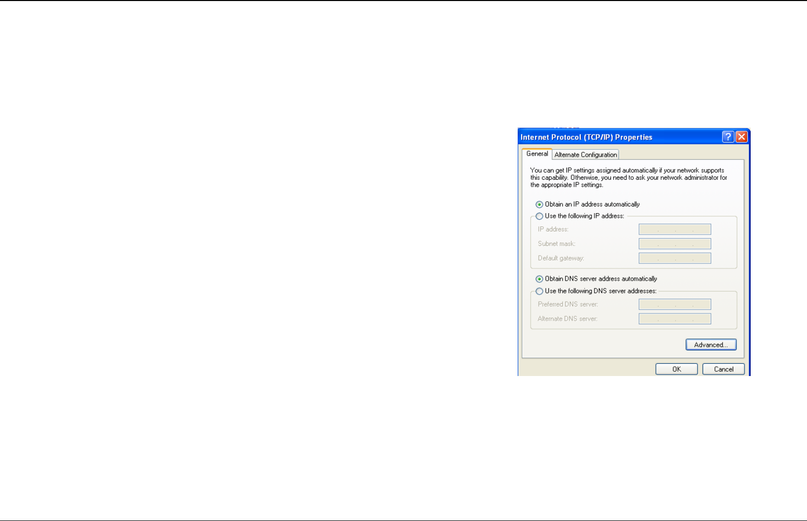
The right figure displays the TCP/IP Properties dialog box on Windows XP.
TCP/IP configuration steps for Windows XP are as follows:
Step 1 Choose Start > Control Panel > Network Connections.
Step 2 Right-click the Ethernet connection icon and choose Properties.
Step 3 On the General tab, select the Internet Protocol (TCP/IP) component and
click Properties. The Internet Protocol (TCP/IP) Properties window
appears.
Step 4 Select the Obtain an IP address automatically button.
Step 5 Select the Obtain DNS server address automatically button.
Click OK to save the settings.
Section 3 – Web Configuration
D-Link DSL-2740E User Manual
14
Web Configuration
This chapter describes how to use Web-based management of the DSL router, which allows you to configure and control all of DSL router features
and system parameters in a user-friendly GUI.
Logging in and Wizard
The following description is a detail “How-To” user guide and is prepared for first time users.
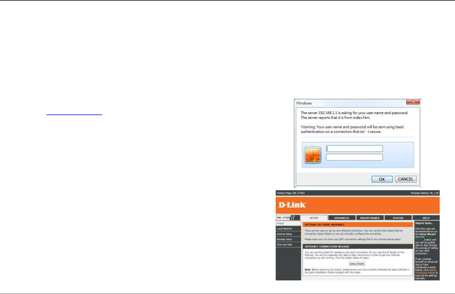
Step 1 Open the Internet Explorer (IE) browser, and then go to
http://192.168.1.1.
Step 2 The Login window will pop up. Enter the username and password. And
then click Login.
The default username and password are both admin.
Select Remember my login info. on this computer, you only need to enter the
password once for the first time logging.
Step 3 After logging in the web configuration page, click on the Setup. The
Wizard page appears as shown on the right. The Wizard page will guide
you to fast configure your router to connect the Internet. Click Setup
Wizard.
Section 3 – Web Configuration
D-Link DSL-2740E User Manual
15
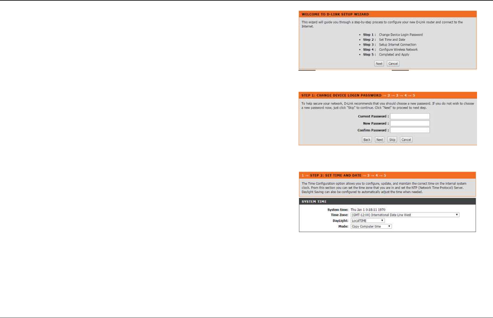
Step 4 In the next page shown on the right, there are 5 steps to configure the
device. Click Next to continue.
Step 5 Set a new login password. If you want to keep the previous password,
click Skip to go to next page directly. After setting a new password, click
Next.
Note:
The login password cannot contain a space.
Step 6 Set the time and date manually or setup a correct NTP server, and then
click Next.
Section 3 – Web Configuration
D-Link DSL-2740E User Manual
16
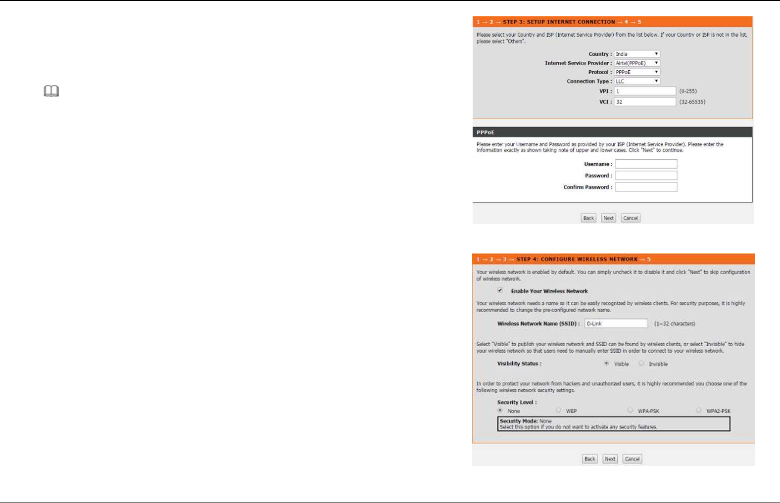
Step 7 Configure the Internet connection.
Please select correct country, ISP and service mode. If PPPoE is select, please
enter the PPPoE sername and Password provided by your ISP.
Click Next to go to the next page.
Note:
Different protocol requires entering different information. You can fill in the
entries according to what your ISP provides you.
Step 8 Configure the wireless network in this page.
1) Check Enable Your Wireless Network.
1) Set the SSID for your wireless network, you can also keep it as default.
2) Choose to display or hide your wireless network.
- Visible: Your wireless network can be detected.
- Invisible: You wireless network cannot be detected. Wireless clients
needs to enter the SSID and password manually to join this wireless
network.
Section 3 – Web Configuration
D-Link DSL-2740E User Manual
17
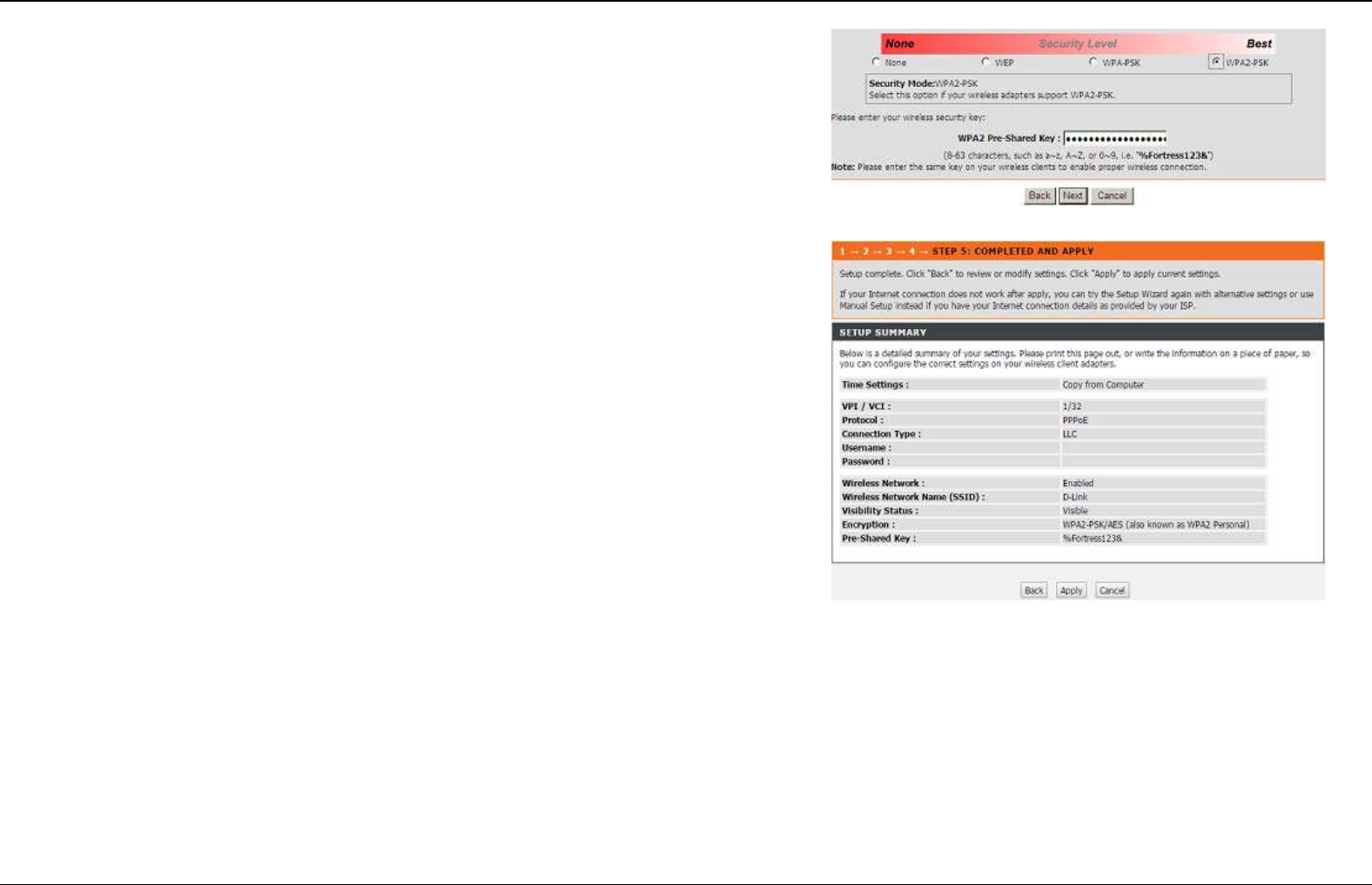
3) Set the security level. The default security level of wireless network is None.
Choose an encryption mode for the wireless network. It is recommended to
choose WPA2-PSK.
4) Enter a new password in WPA2 Pre-Shared Key.
5) Click Next to go to the next page.
Step 9 View the setup summary.
Click Apply to take the setup into effect.
Click Back to modify the setup.
Click Cancel to cancel the whole setup.
Section 4 - Troubleshooting
D-Link DSL-2740E User Manual
18
Setup
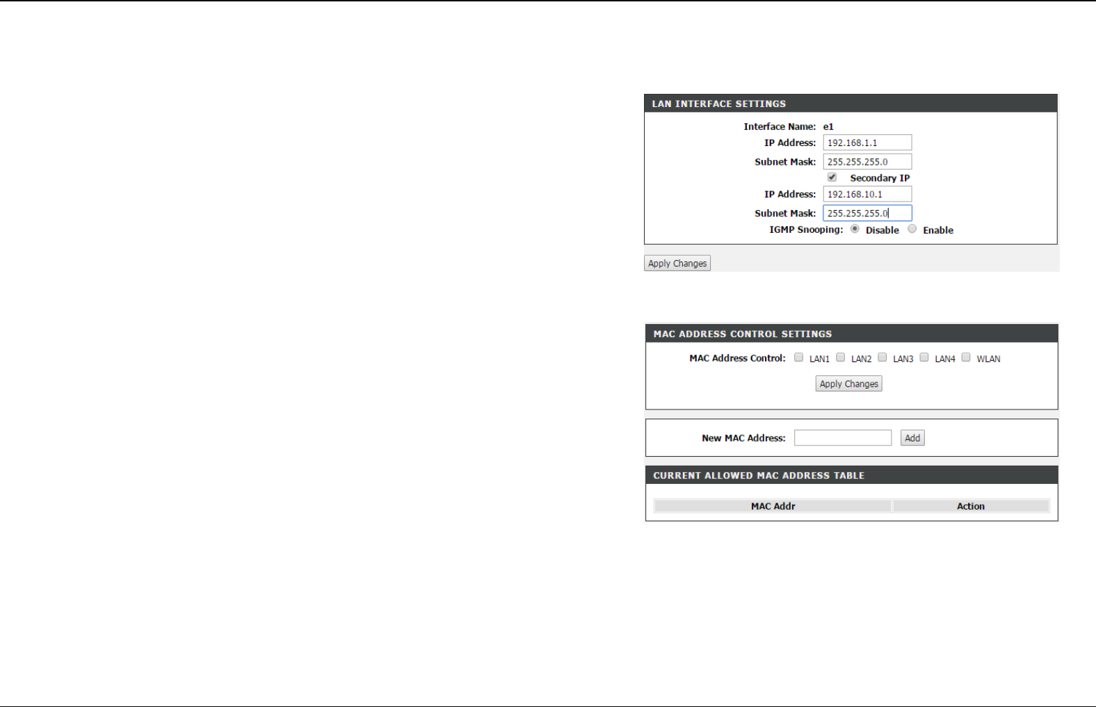
LAN Interface Settings
Choose SETUP > Local Network. The Local Network page shown in the right
figure appears.
To configure the local network of DSL-2740E, do as follow:
Step 1 In the Router IP Address textbox, enter the IP address of LAN
interface. The default IP address is 192.168.1.1. The Router IP
address is the URL address for logging in the Web configuration page.
Step 2 Enter the subnet mask of LAN interface. If the Router IP address is
192.168.1.1, the range of subnet mask is from 255.255.0.0 -
255.255.255.254.
Step 3 Select Secondary IP Address. It enables the secondary LAN IP
address for your router. It will be used when your primary router IP
address is in the same network segment with other LANs. The
Secondary router IP address must be in the different network segment
from the primary one.
Step 4 Enter the secondary router IP address and subnet mask.
Enabling LAN MAC Address Control
Step 1 The MAC Address Control Setting is block list. Only MAC address in
Current Allowed MAC Address Table will be allowed. Enter the MAC address
in the textbox for New MAC Address and then click Add
Step 2 Select the LAN port which would like to enable MAC address control.
Then click Apply Changes.
Section 4 – Troubleshooting
D-Link DSL-2740E User Manual
19
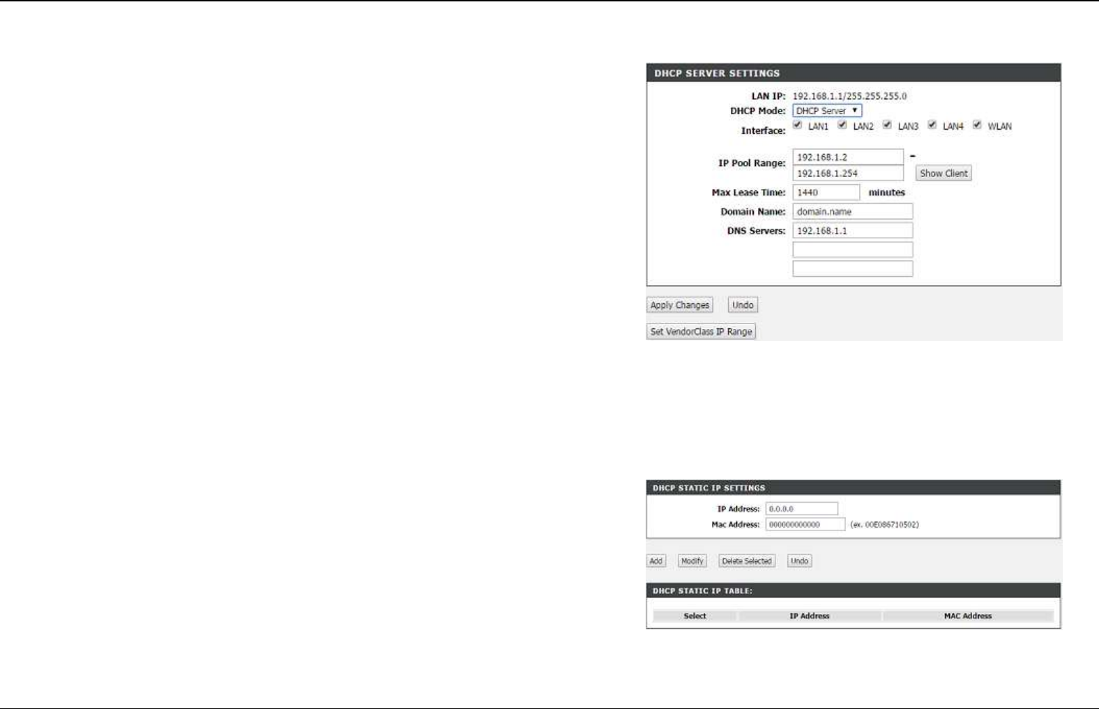
DHCP server
The DHCP Server shown in the right figure appears. It used to assign an IP
address to clients connect to LAN of this CPE.
It is suggest to keep it as default settings.
Step 1 Configure DHCP Server.
- Enable DHCP Relay: Enable the message to transmit between
clients in different network segment.
- Enable DHCP Server: Enable the router to assign IP addresses, IP
default gateway and DNS Servers to the host.
DHCP IP Address Range: It specifies the first IP address in the IP
address pool. The router assigns IP address that base on the IP pool
range to the host.
DHCP Lease Time: The lease time determines the period that the
host retains the assigned IP addresses before the IP addresses
change.
Step 2 Select the LAN or WAN ports which are going to adopt the setting.
Step 3 Click Apply to make the settings take effect.
DHCP reserved
The DHCP Server shown in the right figure appears. It used to assign an IP
address to clients connect to LAN of this CPE.
It is suggest to keep it as default settings.
Section 4 – Troubleshooting
D-Link DSL-2740E User Manual
20
LAN IPv6 Interface
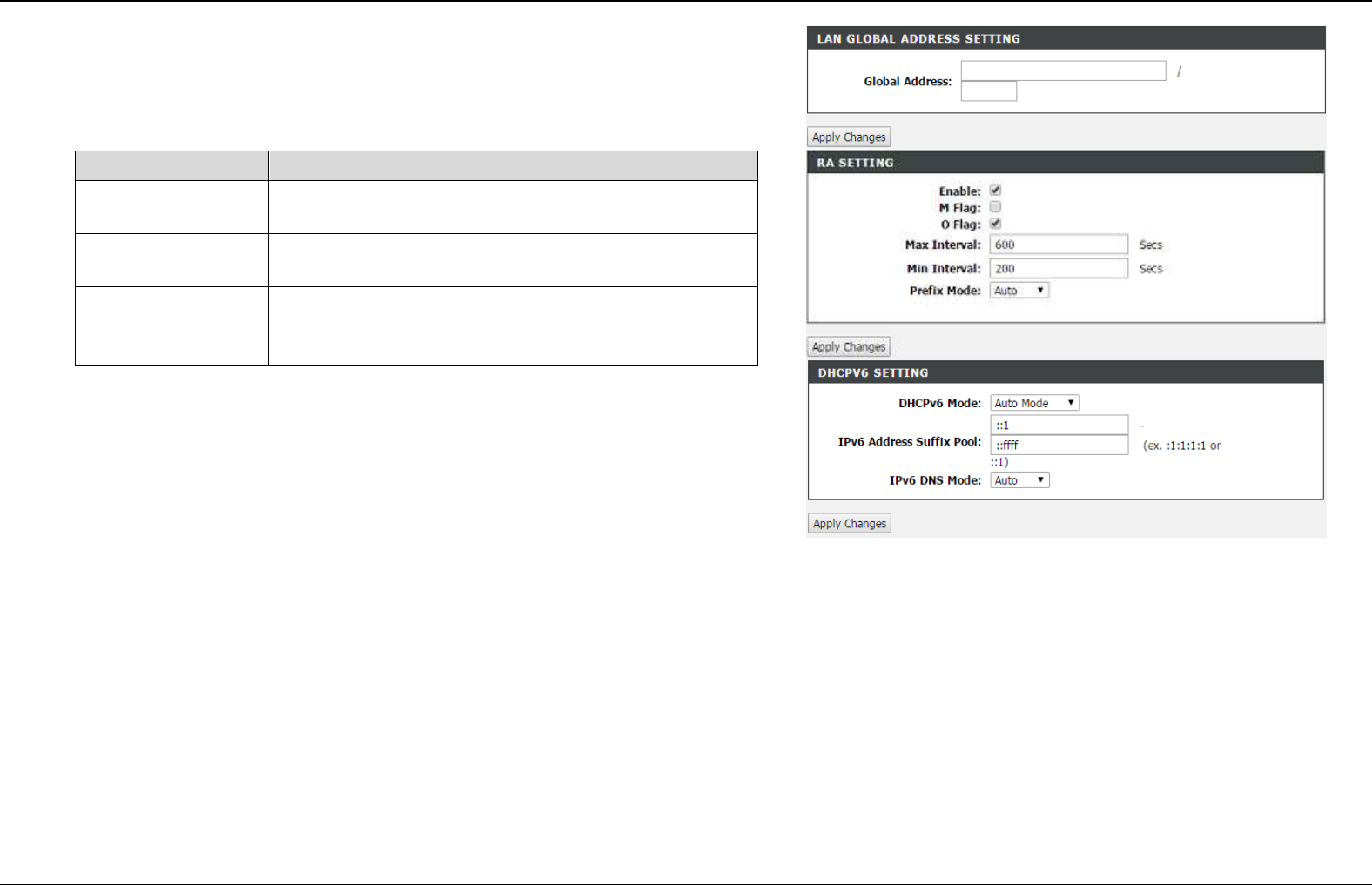
Choose SETUP > LAN IPv6. The page shown in the right figure appears. This
page allows you to configure IPv6 LAN.
The following table describes the parameters of this page.
Field
Description
Global Address
The address through which PCs access the
gateway.
RA settings
Choose to enable or disable RA (Router
Advertisement and related parameters.
DHCPv6 Mode.
Configure DHCPv6 server as auto mode or manual
mode. And configure the suffix pool for LAN side
clients.
Section 4 – Troubleshooting
D-Link DSL-2740E User Manual
21
Internet Setup
Channel Configuration
Choose SETUP > Internet Setup > Channel Config. The page is shown as the
figure appears on the right. In this page, you can add or configure WAN interface
of your router.
Step 1 In the VPI and VCI textbox, enter the VPI and VCI value provided by
your ISP.
Note:
To access the internet, at least one PVC is required to add.
Step 2 In the protocol drop-down list, select the protocol according to the
internet service you subscribed from your ISP. There are 5 types of
protocols: PPP over ATM (PPPoA), PPP over Ethernet (PPPoE),
MAC Encapsulation Routing (1483 MER), IP over ATM (IPoA),
Bridging, 1483 Bridge, 1483 Routed.
Section 4 – Troubleshooting
D-Link DSL-2740E User Manual
22
Adding a PVC in PPPoE or PPPoA mode
If the protocol is selected to PPP over Ethernet (PPPoE) or PPP over ATM
(PPPoA), the page shown as the right figure appears.
1) In Protocol drop-down list, select PPPoE (or PPPoA).
2) In Encapsulation Mode, select an option according to the information
provided by your ISP.
3) Select IPv4 or IPv6 according to the information provided by ISP.
4) In the PPP Username and PPP Password textbox, input the Username
and password of PPPoE account provided by your ISP.
5) In the Dial-up Mode drop-down list, select an option as you demand.
There are 3 modes available: Continuous, Connect On Demand, Manual.
- Continuous: The system automatically keeps dialing for WAN
connection once the connection is off-line.
- Connect On Demand: The system automatically dials for WAN
connection once network access request is detected. If no request is
sent from the LAN within the IdleTime, the system automatically
disconnect from the internet. You can set the Idle Time as you need.
- Manual: Manually dial to connect the WAN once powering on the
Router.
6) For other entries which are not mentioned above, you can keep them as
defaults.
Section 4 – Troubleshooting
D-Link DSL-2740E User Manual
23
1) Adding a PVC in MAC Encapsulation Routing (MER) or IP Over ATM
(IPoA) mode
If the protocol is selected to MAC Encapsulation Routing (MER), the page
shown as the right figure appears.
2) In Protocol drop-down list, select 1483 MER
3) In Encapsulation Mode drop-down list, select an option according to the
information provided by your ISP.
4) Select IPv4 or IPv6 according to the information provided by ISP.
5) In WAN IP Setting section, choose an option according to the information
provided by your ISP.
DHCP: the dynamic WAN IP address will be assigned by your ISP.
Use the following address: A static WAN IP address is provided to
you by your ISP. Input the static WAN IP address and other information provided
by your ISP.
6) For other entries which are not mentioned above, you can keep them as
defaults.
Adding a PVC in Bridging mode
1) In Protocol drop-down list, select 1483 Bridge
2) In Encapsulation Mode drop-down list, select an option according to the
information provided by your ISP.
For PVC in Bridging mode, keep the settings as defaults.
Note:
If the connection protocol is in Bridging mode, the connected PC must
dial for WAN connection with installed dial-up software.
Step 3 After setting (take adding a PPPoE PVC as an example), click Add
and the page skip to the page shown as the right figure appears. You
can edit or delete the PVCs in the table.
Section 4 – Troubleshooting
D-Link DSL-2740E User Manual
24
ATM
Choose SETUP > Internet Setup > ATM settings. The page shown in the right
figure appears.
In this page, it is recommended to keep it as defaults. The device negotiates the
modulation mode with DSLAM.
Click Apply to save the settings.
ADSL
Choose SETUP > Internet Setup > ADSL settings. The page shown in the right
figure appears.
This page is used to configure the parameters for the ATM of your ADSL Router.
Here you may change the setting for VPI, VCI, QoS etc ...
Section 4 – Troubleshooting
D-Link DSL-2740E User Manual
25
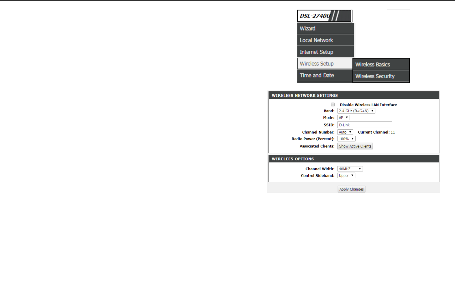
Wireless
This section describes the configuration of 2.4G wireless network.
Choose SETUP > Wireless. The page shown in the right figure appears. This
section contains Wireless Basic and Wireless Security.
Wireless Basic
Choose SETUP > Wireless > Wireless Basic. The page shown as the right
figure appears. In this page, you can configure the parameters of wireless LAN
clients that may connect to the device.
To configure this page, do as follow:
Step 1 Select Enable Wireless.
Step 2 In Wireless Network Name (SSID) textbox, enter a name for your
wireless network. You can also keep it as defaults.
Step 3 Keep other entries as defaults.
Click Apply Changes to save the settings.
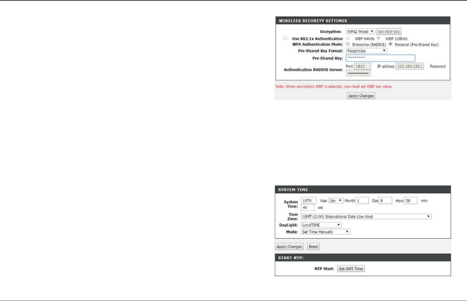
Wireless Security
Choose SETUP > Wireless > Wireless Security. The page shown as the right
figure appears. In this page, you can configure the parameters of wireless LAN
clients that may connect to the device. Wireless security is vital to your network
to protect the wireless communication among wireless stations, access points
and wired network.
Section 4 – Troubleshooting
D-Link DSL-2740E User Manual
26
The default security mode is None. If the security mode is set to None, your
wireless network can be connected by all wireless clients that can detect the
SSID of this network.
If the Security Mode is set to WPA(TKIP), WPA(AES), WPA2(TKIP), WPA(AES),
or WPA2 Mixed,, the page is shown as the right figure appears. Take WPA2
Mixed as an example.
Step 1 In Security Mode drop-down list, select WPA2 Mixed.
Step 2 In WPA Authentication Mode, select Personal (Pre-Share-Key)
Step 3 In Pre-Shared Key Format drop-down list, select Passhrase.
Step 4 Configure the WPA Authentication Mode.
- Personal (Pre-Share-Key): WPA-PSK does not require an
authentication server. You need to set a Pre-shared Key (wireless
network password) for your wireless network.
- Enterprise (RADIUS): When WPA enterprise is enabled, the router
uses EAP (802.1x) to authenticate clients via a remote RADIUS
server. Enter the port, IP address, and password of the Radius
server. The wireless clients are required to enter the username
and password provided by the Radius server.
Step 5 Enter the Pre-Share Key, at least for 8 charcacters..
Step 6 After setting, click Apply Changes to save the settings.
Time and Date
Choose SETUP > Time and Date. The page shown in the right figure appears.
This page allows you to configure IPv6 LAN.
In the Time and Date page, you can configure, update, and maintain the correct
time on the internal system clock. You can set the time zone that you are in and
the network time protocol (NTP) server. You can also configure daylight saving to
automatically adjust the time when needed.
Select Set NTP Server Manually and select the NTP server of D-Link. You can
also specify the NTP server by selecting Other.
Select Daylight if necessary. Set the daylight as you want.
Click Apply Changes to save the settings.
Section 4 - Troubleshooting
D-Link DSL-2740E User Manual
27
Advanced
This section includes advanced features for network management, security and administrative tools to manage the device. You can view status and
other information used to examine performance and troubleshoot.
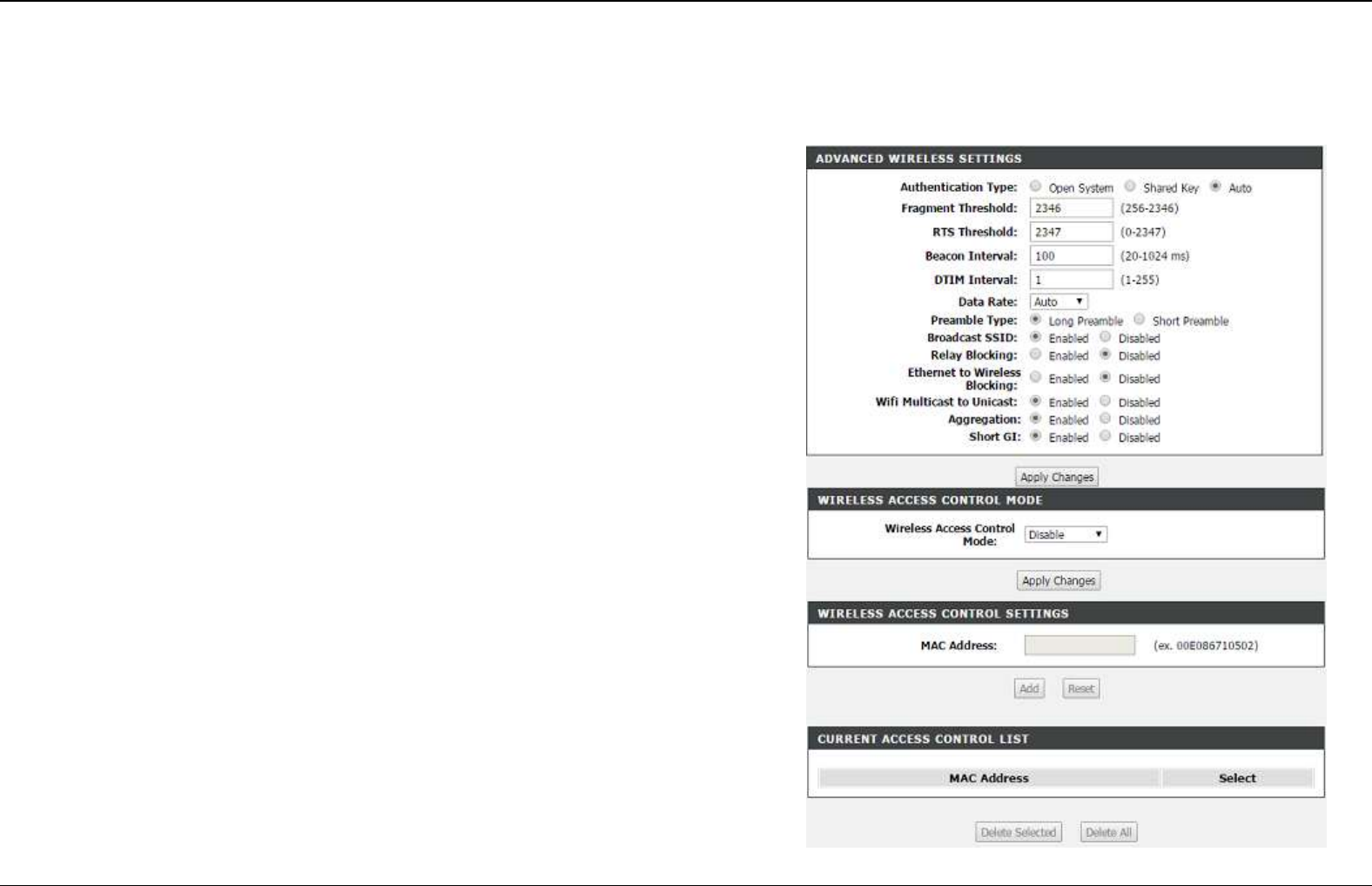
Advanced Wireless
Choose ADVANCED > Advanced Wireless > Wireless Advanced. The page
shown in the right figure appears.
If you’re not sure what you’re configuring, please leave it as default.
Access Control
Choose ADVANCED > Advanced Wireless > Access Control. The page
shown in the right figure appears.
1. Select Wireless Access Control Mode to Allow Listed or Deny Listed
2. Add MAC address to the list.
Only the MAC addresses in the listed will be allowed or denied according to what
mode is selected.
Section 4 – Troubleshooting
D-Link DSL-2740E User Manual
28
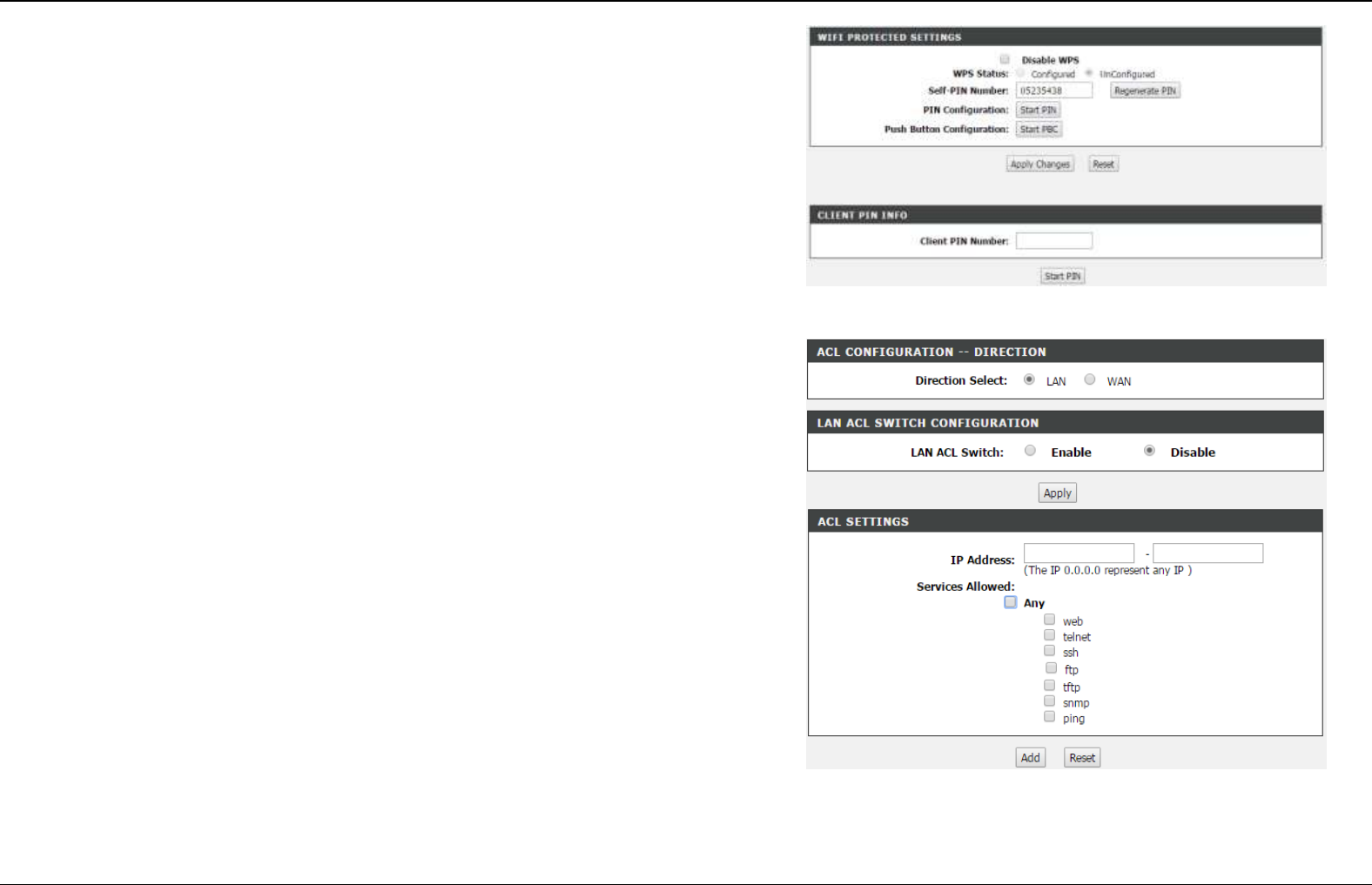
WPS
There are 3 methods to realize wireless connection through WPS.
- PBC
Click the Start PBC button in this page. And then click WPS button on the client
to be connected within 2 minutes. The connection will be established.
- Based on the PIN of wireless client to be connected.
In Input Client PIN textbox, input the PIN code of the wireless client to be
connected. And then click on Start PIN
- Based on the PIN of DSL-2740E.
1) Select Enabled to enable WPS.
4) Input the Self-PIN number at wireless client to be connected.
Access Control List
You can specify what services are accessible form LAN or WAN parts. Entries
in this ACL table are used to permit certain types of data packets from your local
network or Internet network to the Gateway. Using of such access control can
be helpful in securing or restricting the Gateway management.
Select direction, LAN ACL Switch and click Apply to save the settings.
In ACL settings, please enter the IP address range and check which service to
configure. Then click Add to create a new rule.
Section 4 – Troubleshooting
D-Link DSL-2740E User Manual
29
Access Control List IPv6
You can specify what services are accessible form LAN or WAN parts. Entries
in this ACL table are used to permit certain types of data packets from your local
network or Internet network to the Gateway. Using of such access control can
be helpful in securing or restricting the Gateway management.
Select direction, LAN ACL Switch and click Apply to save the settings.
In ACL settings, please enter the IP address range and check which service to
configure. Then click Add to create a new rule.
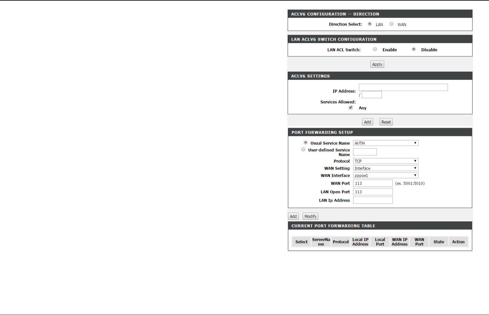
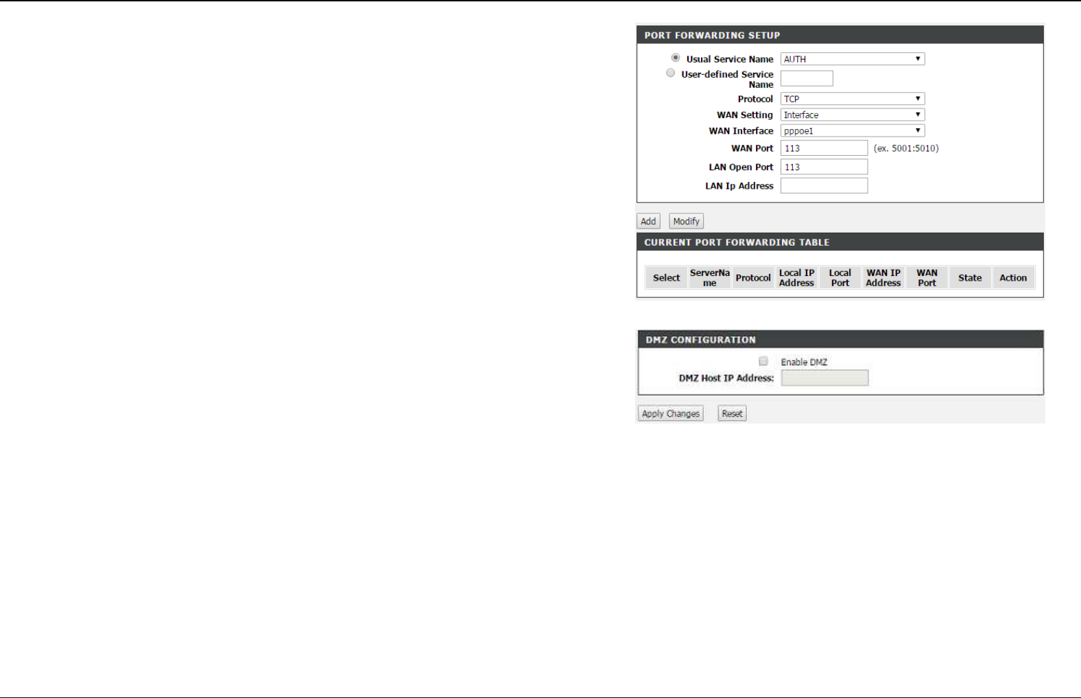
Port Forwarding
Choose ADVANCED > Port Forwarding. The page shown in the right figure
appears.
This function is used to open ports in your device and re-direct data through
those ports to a single PC on your network (WAN-to-LAN traffic). It allows remote
users to access services on your LAN, such as FTP for file transfers. The device
accepts remote requests for these services at your global IP address. It uses the
specified TCP or UDP protocol and port number, and redirects these requests to
the server on your LAN with the LAN IP address which within the available range
of the subnet where the device is in.
Enter an IP address in the WAN IP address field when IP Address is selected in
WAN settings or select the interface name
The Ports show the ports that you want to open on the device. The TCP/UDP
means the protocol type of the opened ports.
Click Add to create a new rule.
Section 4 – Troubleshooting
D-Link DSL-2740E User Manual
30
Port Trigger
Choose ADVANCED > Port Trigger The page shown in the right figure appears.
Some applications require that specific ports in the Router's firewall be opened
for access by the remote parties. Port Trigger dynamically opens up the "Relate
Port" in the firewall when an application on the LAN initiates a TCP/UDP
connection to a remote party using the "Match Port". The Router allows the
remote party from the WAN side to establish new connections back to the
application on the LAN side using the "Relate Port".
Entries in this table are used to restrict certain types of data packets from your
local network to Internet through the Gateway. Use of such filters can be helpful
in securing or restricting your local network.
DMZ
DMZ is the abbreviation of the Demilitarized Zone. Since some applications are
not compatible with NAT, the device supports the use of a DMZ IP address for a
single host on the LAN. This IP address is not protected by NAT and it is visible
to agents on the Internet with the correct type of software. Note that any client
PC in the DMZ is exposed to various types of security risks. If you use the DMZ,
take measures (such as client-based virus protection) to protect the remaining
client PCs on your LAN from possible contamination through DMZ.
Choose ADVANCED > DMZ. The page shown in the right figure appears.
Input the host IP address. And Click Apply Changes to save the settings.
Section 4 – Troubleshooting
D-Link DSL-2740E User Manual
31
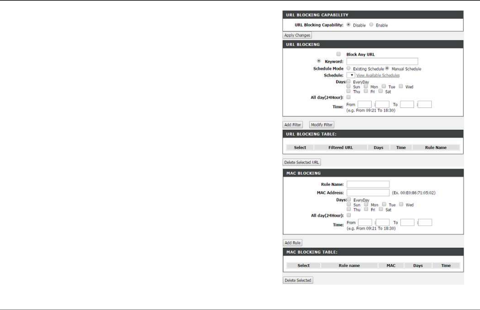
Parental Control
This page provides two useful tools for restricting the Internet access. URL
Block allows you to quickly create a list of all websites that you wish to stop
users from accessing. MAC Filter allows you to control when clients or PCs
connected to the device are allowed to access the Internet.
Choose ADVANCED > Parental Control > URL Block. The URL Block page
shown in the right figure appears.
Step 1 Enter the key word of website in the Keyword field.
Step 2 Select the corresponding time and days.
Step 3 Click Add Filter.
MAC Blocking
Choose ADVANCED > Parental Control > MAC Blocking. The page shown in
the right figure appears.
Enter the Rule Name, MAC address to be blocked and configure the
time/schedule accordingly.
Click Add Rule to add it in the MAC Blocking Table,
Section 4 – Troubleshooting
D-Link DSL-2740E User Manual
32
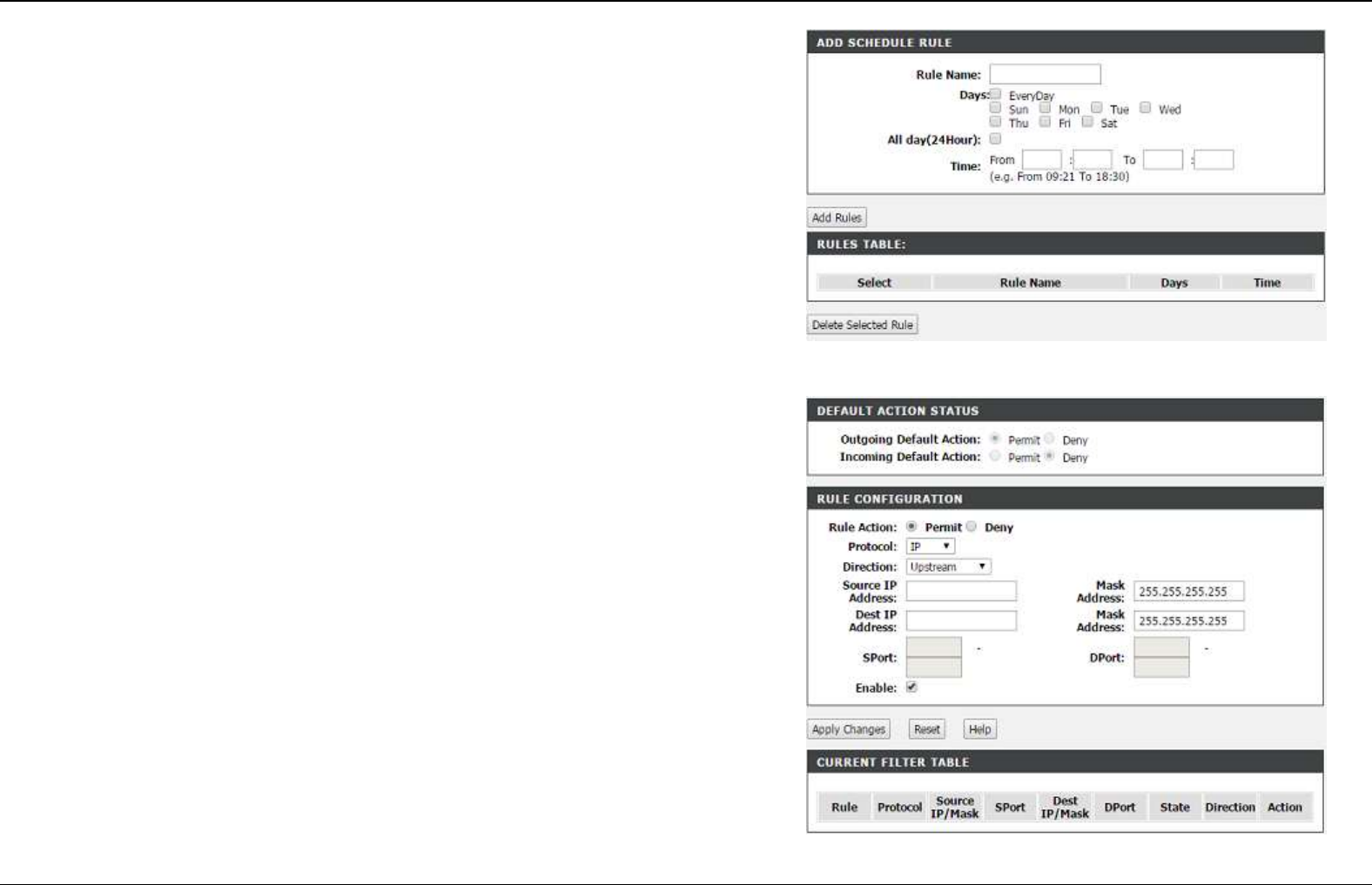
Schedule
Choose ADVANCED > Parental Control > Schedule. The page shown in the
right figure appears.
The schedule created here could be used for the URL blocking or MAC
blocking.
Filtering Options
IP/Port Filtering
Choose ADVANCED > Filtering Options > IP/Port Filtering. The page shown
in the right figure appears. In this page, you may configure IP filtering function.
specify the criteria: Rule Action, Protocol, Direction, Source IP/Mask, Des
IP/Mask,
Click Apply Changes to create a new rule.
Section 4 – Troubleshooting
D-Link DSL-2740E User Manual
33
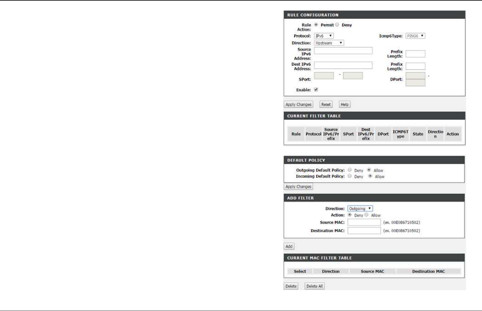
IPv6/Port Filtering
Choose ADVANCED > Filtering Options > IPv6/Port Filtering. The page
shown in the right figure appears. In this page, you may configure IPv6 filtering
function.
specify the criteria: Rule Action, Protocol, Direction, Source IP/Mask, Des
IP/Mask,
Click Apply Changes to create a new rule.
MAC Filtering
Choose ADVANCED > Filtering Options > MAC Filtering. The page shown in
the right figure appears. In this page, you may configure MAC Filtering function.
specify the criteria: Action, Direction, Source MAC, Des MAC, and then
Click Apply Changes to create a new rule.
Section 4 – Troubleshooting
D-Link DSL-2740E User Manual
34
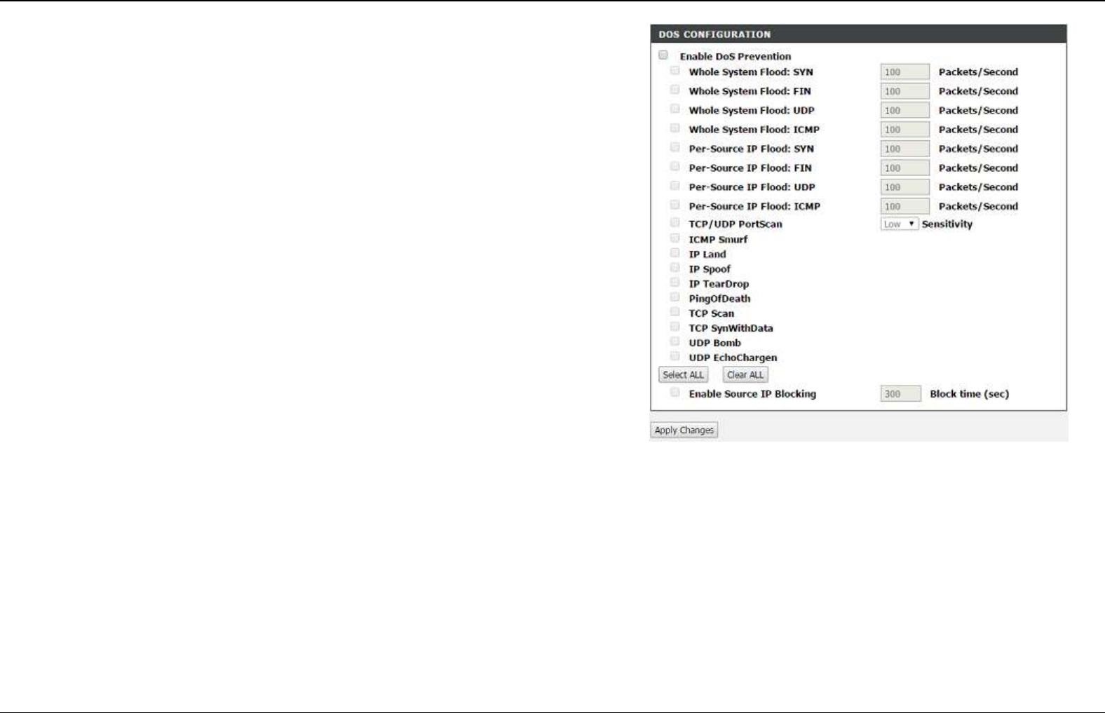
DOS settings
A denial-of-service (DoS) attack is characterized by an explicit attempt by
attackers to prevent legitimate users of a service from using that service.
Port scan protection is designed to block attempts to discover vulnerable ports or
services that might be exploited in an attack from the WAN.
Choose ADVANCED > DOS settings. The page shown in the right figure
appears. In this page, you may configure IP firewall function.
Check the protections and click on Apply Changes to enable the protection. You
might consult your ISP for which protection should be enabled.
Section 4 – Troubleshooting
D-Link DSL-2740E User Manual
35
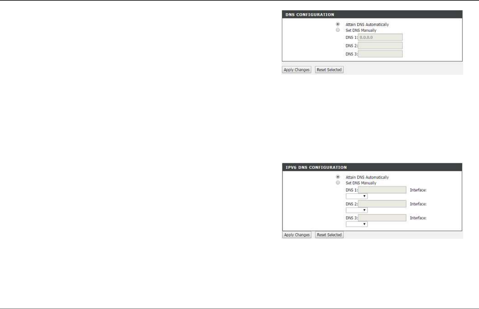
DNS
Domain name system (DNS) is an Internet service that translates domain names
into IP addresses. Because domain names are alphabetic, they are easier to
remember. The Internet, however, is actually based on IP addresses. Each time
you use a domain name, a DNS service must translate the name into the
corresponding IP address. For example, the domain name www.example.com
might be translated to 198.105.232.4.
The DNS system is, in fact, its own network. If one DNS server does not know
how to translate a particular domain name, it asks another one, and so on, until
the correct IP address is returned.
Choose ADVANCED > DNS. The page shown in the right figure appears.
If you are using the device for DHCP service on the LAN or using DNS servers
on the ISP network, select Attain DNS Automatically.
If you have DNS IP addresses provided by your ISP, enter these IP addresses in
the available entry fields for the preferred DNS server and the alternate DNS
server.
Click Apply Changes to save the settings.
IPv6 DNS
Choose ADVANCED > IPv6 DNS. The page shown in the right figure appears.
If you are using the device for DHCP service on the LAN or using DNS servers
on the ISP network, select Attain DNS Automatically.
If you have DNS IP addresses provided by your ISP, enter these IP addresses in
the available entry fields for the preferred DNS server and the alternate IPv6
DNS server.
Click Apply Changes to save the settings.
Section 4 – Troubleshooting
D-Link DSL-2740E User Manual
36
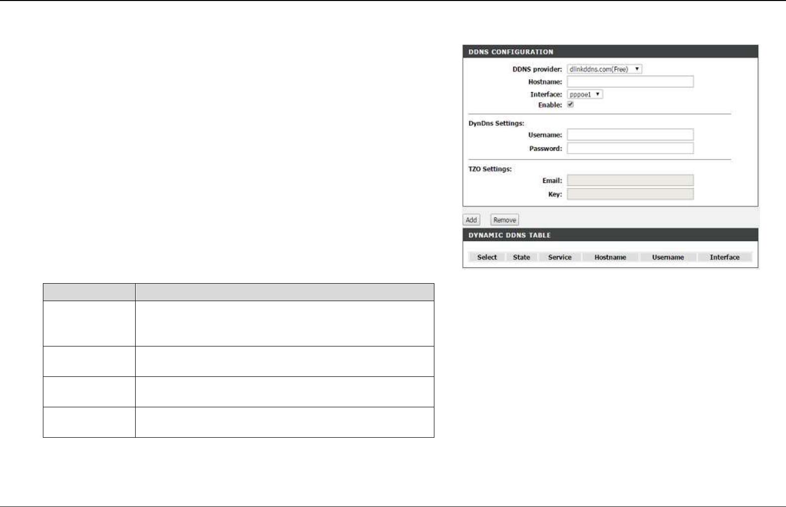
Dynamic DNS
The device supports dynamic domain name service (DDNS). The dynamic DNS
service allows a dynamic public IP address to be associated with a static host
name in any of the many domains, and allows access to a specified host from
various locations on the Internet. Click a hyperlinked URL in the form of
hostname.dyndns.org and allow remote access to a host. Many ISPs assign
public IP addresses using DHCP, so locating a specific host on the LAN using
the standard DNS is difficult. For example, if you are running a public web server
or VPN server on your LAN, DDNS ensures that the host can be located from the
Internet even if the public IP address changes. DDNS requires that an account
be set up with one of the supported DDNS service providers (DyndDNS.org or
dlinkddns.com).
Choose ADVANCED > Dynamic DNS. The page shown in the right page
appears.
Click Add to add dynamic DNS.
The following table describes the parameters of this page.
Field
Description
D
DDNS
provider
Select one of the DDNS registration organizations
from the down-list drop. Available servers include
DynDns.org and dlinkddns.com.
H
Host Name
Enter the host name that you registered with your
DDNS service provider.
U
Username
Enter the user name for your DDNS account.
P
Password
Enter the password for your DDNS account.
Click Apply Change to save the settings.
Section 4 – Troubleshooting
D-Link DSL-2740E User Manual
37
Network Tools
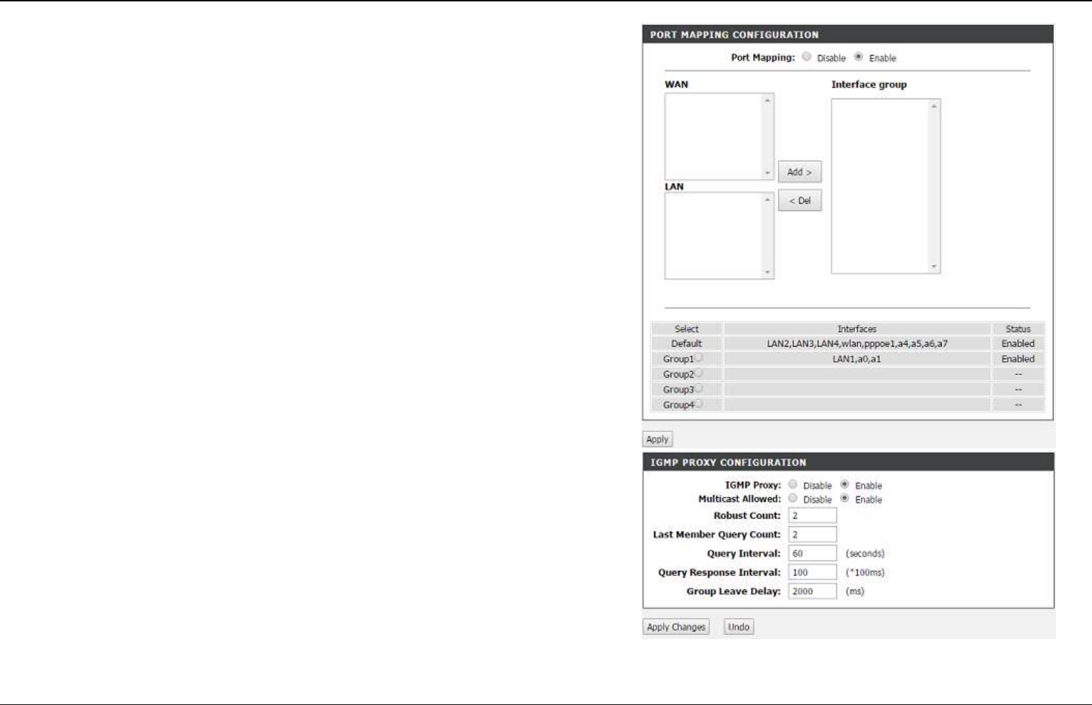
Port Mapping
Choose ADVANCED > Network Tools > Port Mapping. The page shown in the
right figure appears. In this page, you can bind the WAN interface and the LAN
interface to the same group.
Click Add to add port mapping.
The procedure for creating a mapping group is as follows:
Step 1 Select the group to be configured.
Step 2 Select interfaces from the Available Interface list and click the Add >
button to add them to the grouped interface list, in order to create the
required mapping of the ports. Or select the interface in Interface
group and click < Del to remove it from current group.
Step 3 Click Apply to save the settings.
IGMP Proxy
Choose ADVANCED > Network Tools > IGMP Proxy. The page shown in the
right figure appears.
IGMP proxy enables the system to issue IGMP host messages on behalf of hosts
that the system discovered through standard IGMP interfaces. The system acts
as a proxy for its hosts after you enable it.
Section 4 – Troubleshooting
D-Link DSL-2740E User Manual
38
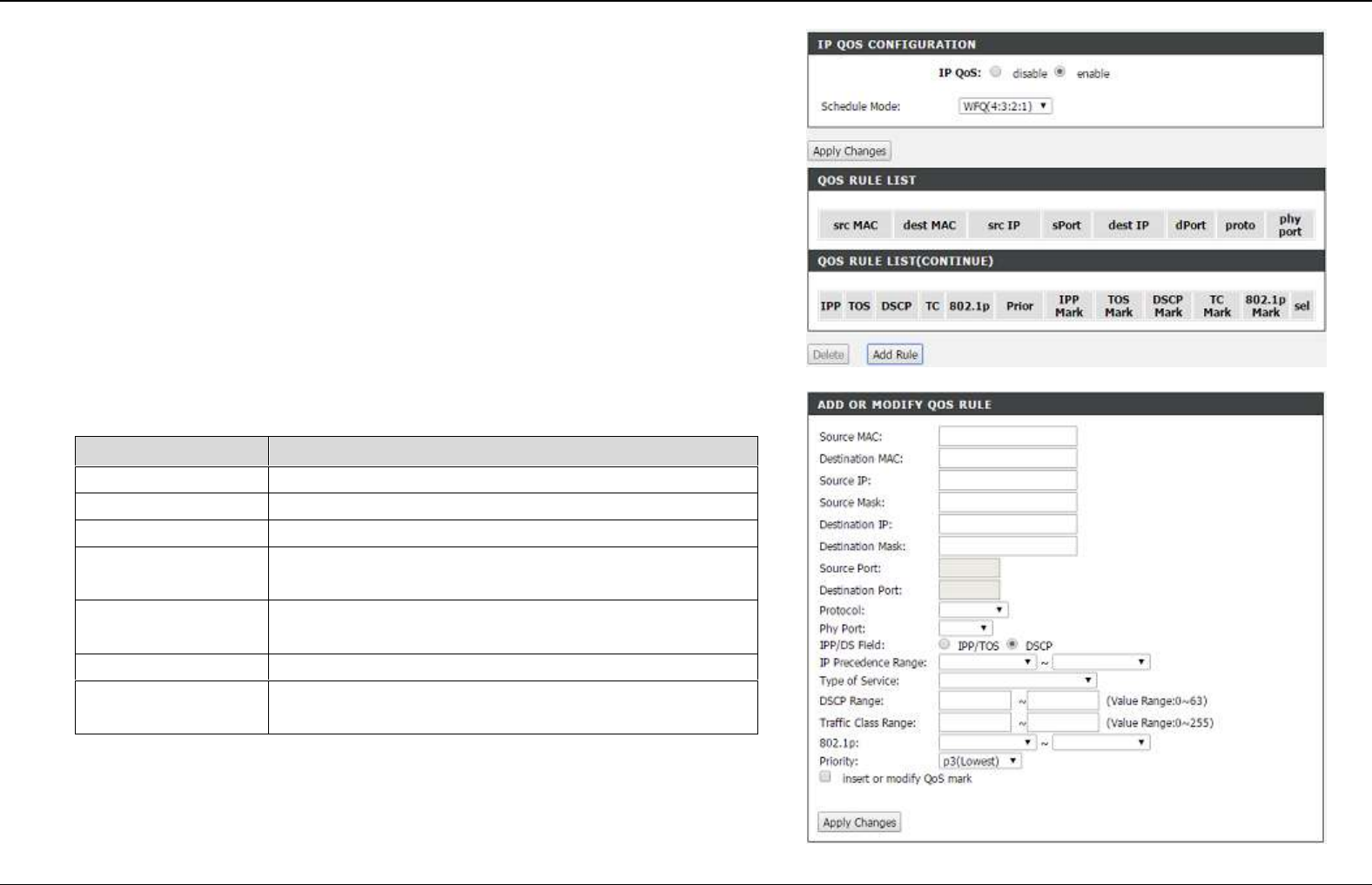
IP QoS Configuration
Choose ADVANCED > Network Tool >QoS Configuration. The page shown in
the right figure appears. The QoS Configuration contains 3 parts: IP QoS
Configuration, QoS Rule list.
IP QoS Configuration
Choose ADVANCED > QoS Configuration > Configure QoS Global Options.
The page shown in the right figure appears. You can tick in the checkbox and
then click Submit to enable queuing operation.
Click Add Rule.
The following table describes the parameters of this page.
Field
Description
MAC
Specify Source MAC and Destination MAC.
Ip/mask
Specify Source IP/Mask and Dest IP/Mask
Port
Specify TCP port.
Protocol Type
Choose a protocol type matching with the QoS
rule.
Phy Port
Based on the Classify Type, choose a WAN/LAN
interface.
IPP/DS field
Select TOS or DSCP QoS
Ranges
Select or enter corresponding QoS value ranges
according to the IPP/DS field.
click Apply Changes to apply the settings.
Section 4 – Troubleshooting
D-Link DSL-2740E User Manual
39
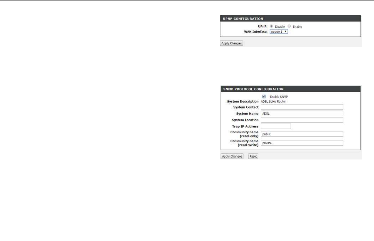
UPNP
Choose ADVANCED > Network Tools > UPnP. The page shown in the right
figure appears.
In this page, you can configure universal plug and play (UPnP). The system acts
as a daemon after you enable UPnP.
UPnP is used for popular audio visual software. It allows automatic discovery of
your device in the network. If you are concerned about UPnP security, you can
disable it. Block ICMP ping should be enabled so that the device does not
respond to malicious Internet requests.
Click Apply Changes to save the settings.
SNMP
Choose ADVANCED > Network Tools > SNMP. The page shown in the right
figure appears. In this page, you can set SNMP parameters.
Section 4 – Troubleshooting
D-Link DSL-2740E User Manual
40
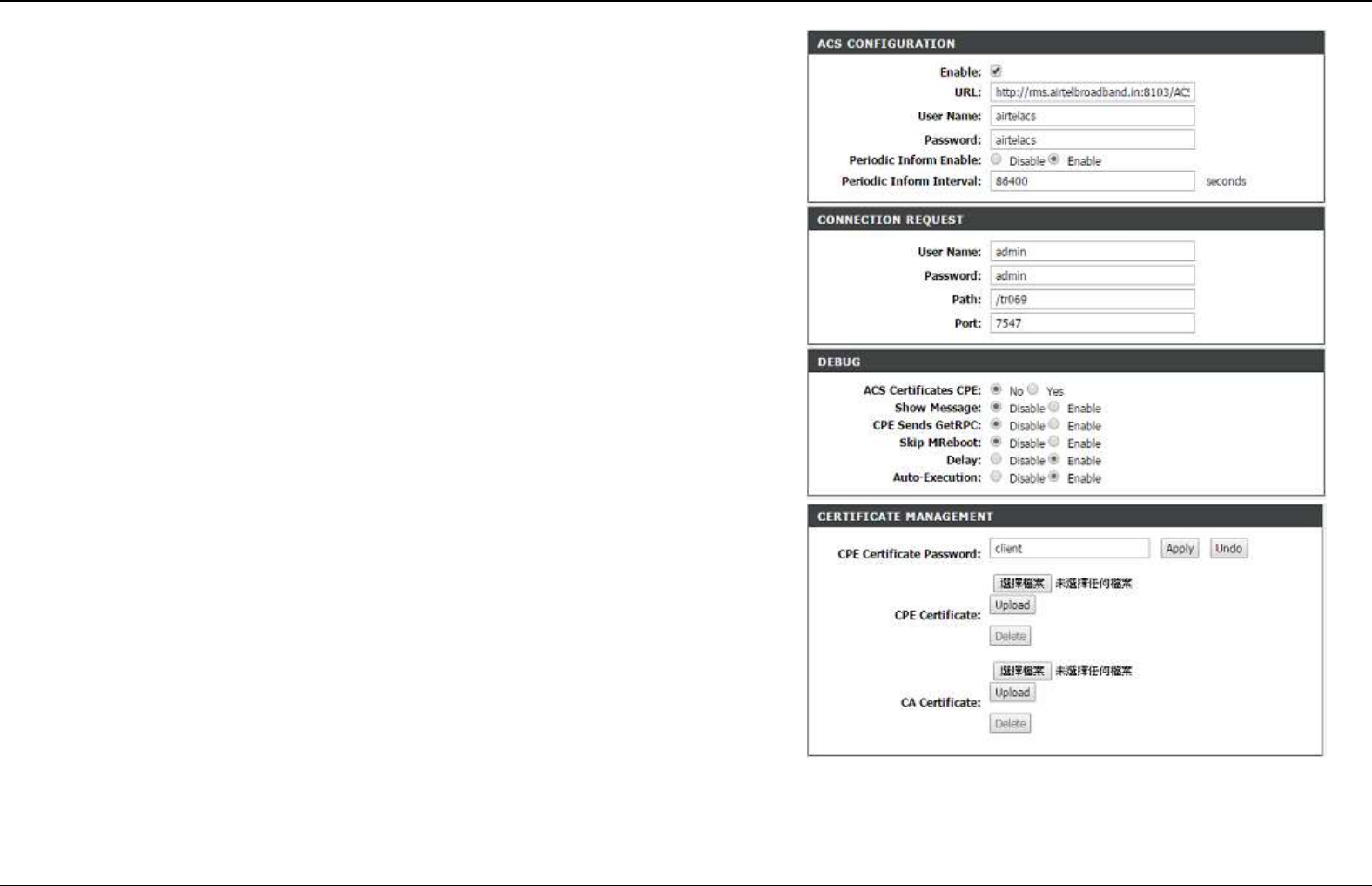
TR-069
Choose ADVANCED > Network Tools > TR-069. The page shown in the right
figure appears. In this page, In this page, you can configure the TR069 CPE.
Certificates
Here you can import the CA for TR-069.
Section 4 – Troubleshooting
D-Link DSL-2740E User Manual
41
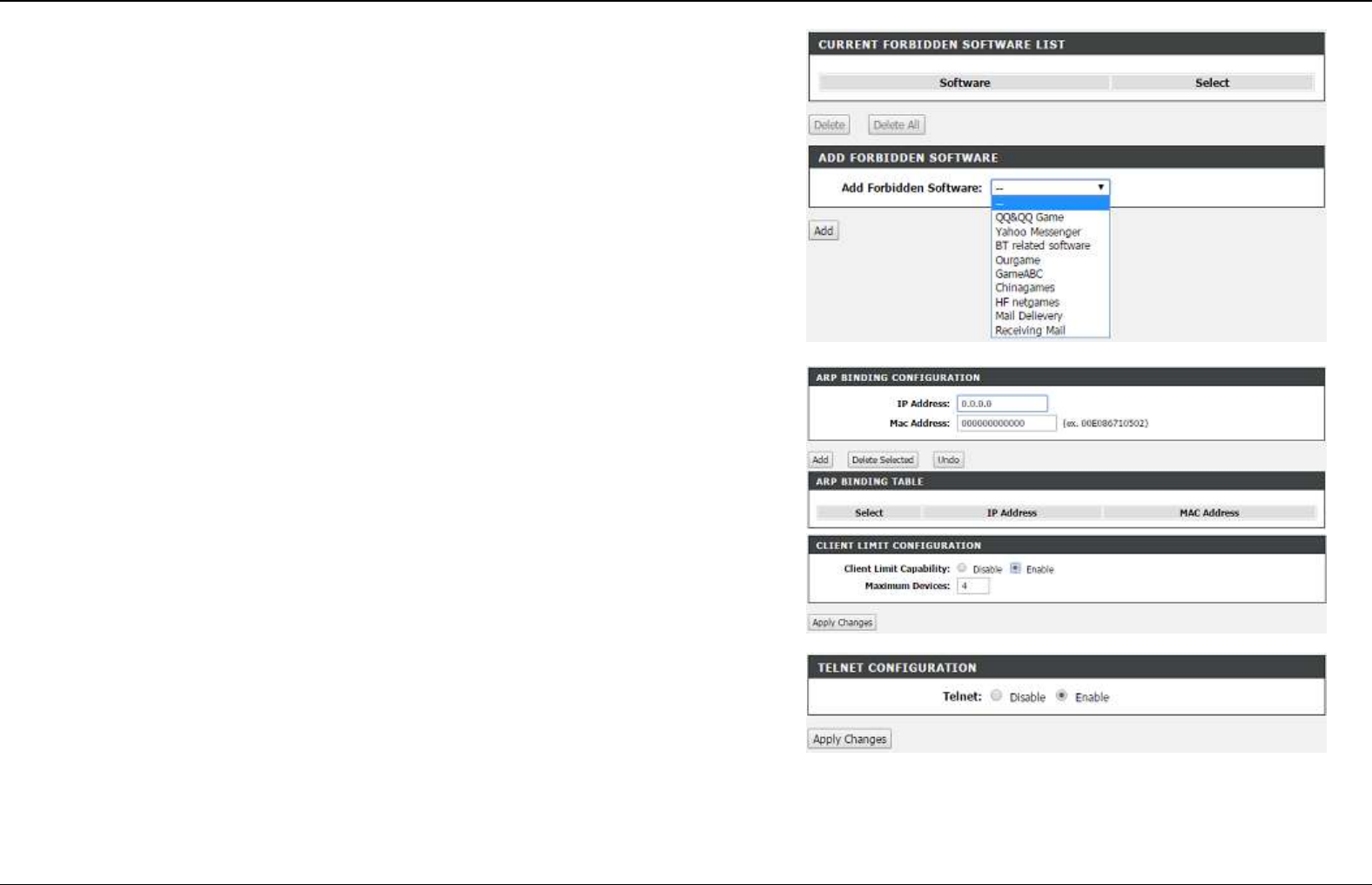
Software Forbidden
Choose ADVANCED > Network Tools > Software Forbidden. The page shown
in the right figure appears. This page is used to configure some software to be
forbidden. By it ,you can deny the IP packets from the specified software.
ARP Binding
Choose ADVANCED > Network Tools > ARP Binding. The page shown in the
right figure appears. This page lists the permanent arp entry table.You can bind
ip with corresponding mac to avoid arp spoof.
Client Limit
Choose ADVANCED > Network Tools > Client Limit. The page shown in the
right figure appears. This page is used to configure the capability of force how
many device can access to Internet.
Telnet
Choose ADVANCED > Network Tools > Telnet. The page shown in the right
figure appears. This page is used to configure telnet function
Section 4 – Troubleshooting
D-Link DSL-2740E User Manual
42
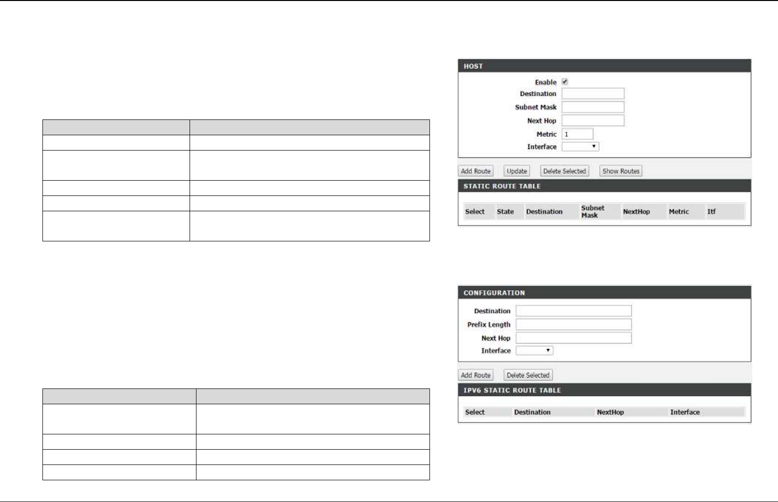
Routing
Static Routing
Choose ADVANCED > Routing > Static Route. The page shown in the right
figure appears. This page is used to configure the routing information. In this
page, you can add or delete IP routes.
The following table describes the parameters of this page.
Field
Description
Destination
The destination IP address of the router.
Subnet Mask
The subnet mask of the destination IP
address.
Next hop
The gateway IP address of the router.
Metric
The cost of this route.
Interface
The interface name of the router output
port.
Click Add Route to add a static route.
IPv6 Static Routing
Choose ADVANCED > Routing > IPv6 Static Route. The page shown in the
right figure appears. This page is used to configure the routing information. In
this page, you can add or delete IP routes.
Click Add to add a static route.
The following table describes the parameters of this page.
Field
Description
Destination
The destination IP address of the static
route.
Prefix length
The length of prefix for this route.
Next Hop
The gateway IP address of the static route.
Interface
The interface name of the static route.
Section 4 – Troubleshooting
D-Link DSL-2740E User Manual
43
Click Add Route to save the settings.
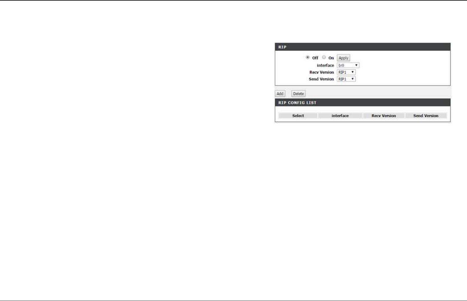
RIP
Choose ADVANCED > Routing > RIP. The page shown in the right figure
appears. This page is used to select the interfaces on your device that use RIP
and the version of the protocol used.
Section 4 – Troubleshooting
D-Link DSL-2740E User Manual
44
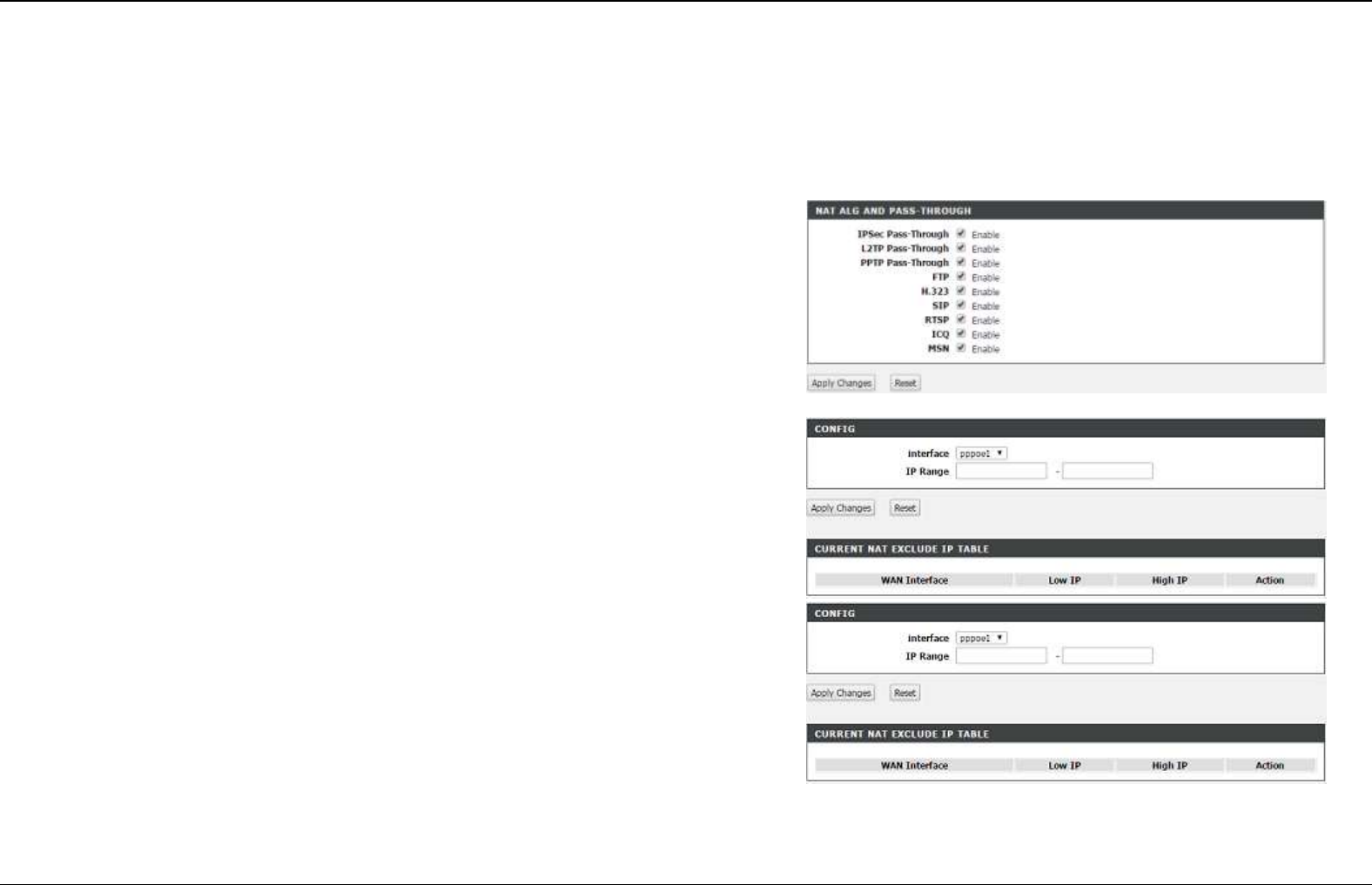
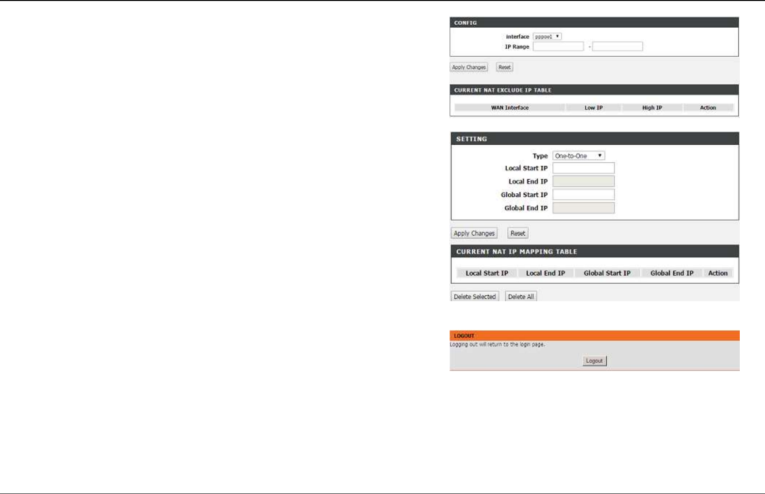
NAT
Traditional NAT would allow hosts within a private network to transparently
access hosts in the external network, in most cases. In a traditional NAT,
sessions are uni-directional, outbound from the private network. Sessions in the
opposite direction may be allowed on an exceptional basis using static address
maps for pre-selected hosts.
Choose ADVANCED > NAT > NAT ALG. The page shown in the right figure
appears.
Setup NAT ALG and Pass-Through configuration
After setting, click Apply Changes to make the settings take effect.
NAT EXCLUDE IP
Choose ADVANCED > NAT > NAT Exclude IP. The page shown in the right
figure appears.
In the page ,you can config some source ip address which use the purge route
mode when access internet through the specified interface.
NAT Forwarding
Choose ADVANCED > NAT > NAT Forwarding. The page shown in the right
figure appears.
Entries in this table allow you to automatically redirect common network services
to a specific machine behind the NAT firewall. These settings are only necessary
if you wish to host some sort of server like a web server or mail server on the
private local network behind your Gateway's NAT firewall.
Section 4 – Troubleshooting
D-Link DSL-2740E User Manual
45
NAT Forwarding
Choose ADVANCED > NAT > FTP ALG config. The page shown in the right
figure appears.
This page is used to configure FTP Server ALG and FTP Client ALG ports .
NAT IP Mapping
Choose ADVANCED > NAT > NAT IP Mapping. The page shown in the right
figure appears.
Entries in this table allow you to config one IP pool for specified source ip
address from lan,so one packet which's source ip is in range of the specified
address will select one IP address from pool for NAT.
Logout
Choose ADVANCED > Logout. The page shown in the right figure appears. In
this page, you can log out of the configuration page.
Section 4 – Troubleshooting
D-Link DSL-2740E User Manual
46
MAINTAINANCE
In the main interface, click MAINTAINANCE tab to enter the maintenance menu. The submenu of the Management contains System, Firmware
Upgrade, Password , Diagnosis, system Log Configuration and Logout.
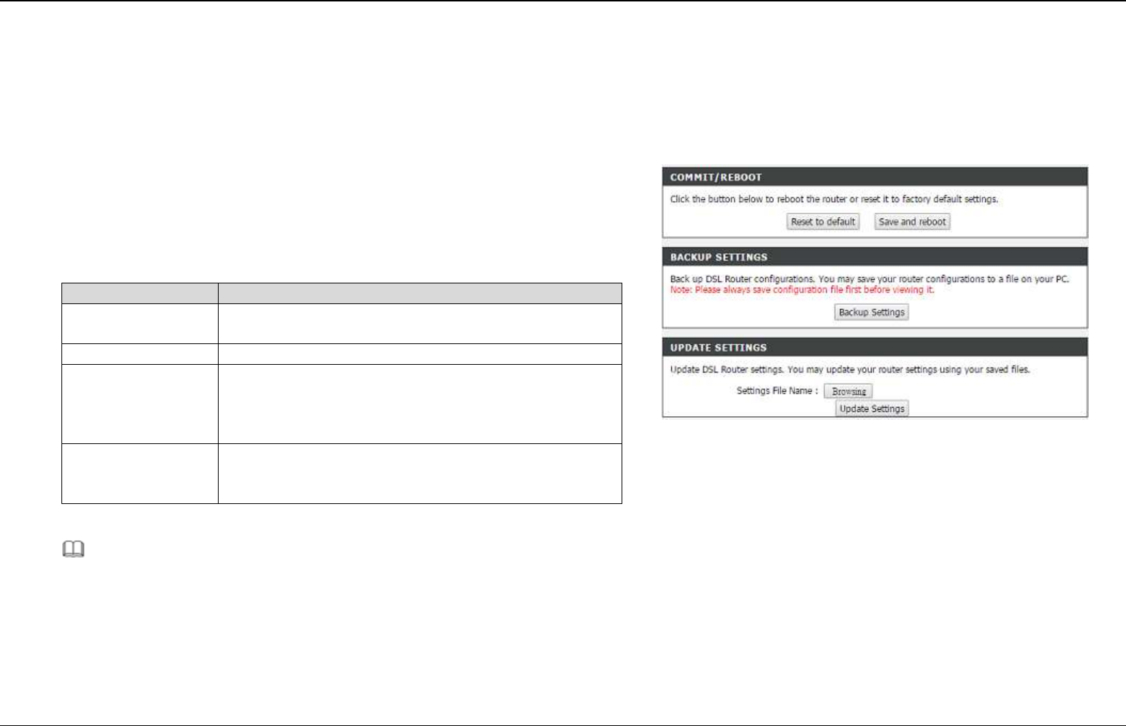
System
Choose MAINTAINANCE > System. The page shown in the right figure
appears.
In this page, you can reboot device, back up the current settings to a file, update
settings from the file saved previously and restore the factory defaults.
The buttons in this page are described as follows:
Field
Description
Restore to Default
Setting
Click this button to reset the device to default
settings.
Save and Reboot
Click this button to reboot the device.
Backup Setting
Click this button to save the settings to the local
hard drive. Select a location on your computer to
back up the file. You can name the configuration
file.
Update settings
Click Browse to select the configuration file of
device and then click Update Settings to begin
updating the device configuration.
Note:
Do not turn off your device or press the Reset button while an operation in
this page is in progress.
Section 4 – Troubleshooting
D-Link DSL-2740E User Manual
47
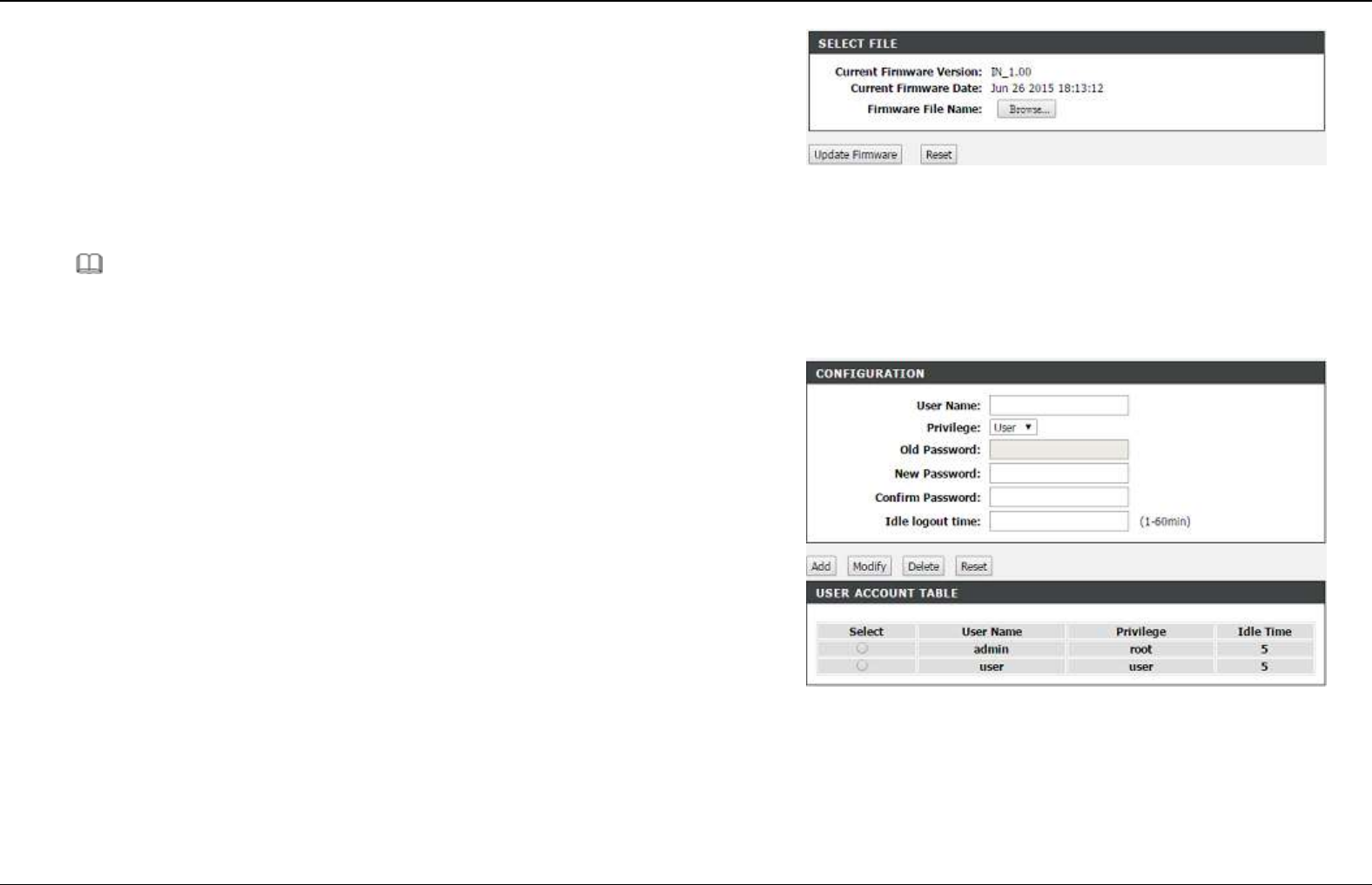
Firmware Upgrade
Choose MAINTAINANCE > Firmware Update. The page shown in the right
figure appears. In this page, you can upgrade the firmware of the device.
To update the firmware, take the following steps.
Step 1 Click Browse…to find the file.
Step 2 Click Update Firmware to copy the file.
The device loads the file and reboots automatically.
Note:
Do not turn off your device or press the Reset button while an operation in
this page is in progress.
Password
Choose MAINTAINANCE > Password. The page shown in the right figure
appears. In this page, you can change the password of the user and set time for
automatic logout.
You should change the default password to secure your network. Ensure that
you remember the new password or write it down and keep it in a safe and
separate location for future reference. If you forget the password, you need to
reset the device to the factory default settings and all configuration settings of the
device are lost.
Enter the current and new passwords and confirm the new password to change
the password. Click Add or Modify to apply the settings.
Section 4 – Troubleshooting
D-Link DSL-2740E User Manual
48
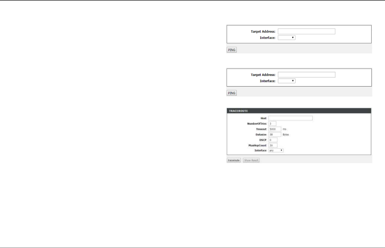
Diagnosis
Ping
Choose MAINTAINANCE > Diagnosis > Ping. The page shown in the right
figure appears. In this page, you can determine the routers on the Internet by
sending packets.
Ping
Choose MAINTAINANCE > Diagnosis > Ping. The page shown in the right
figure appears. In this page, you can determine the routers on the Internet by
sending packets.
Traceroute
Choose MAINTAINANCE > Diagnosis > Traceroute. The page shown in the
right figure appears. In this page, you can determine the routers on the Internet
by sending packets.
Section 4 – Troubleshooting
D-Link DSL-2740E User Manual
49
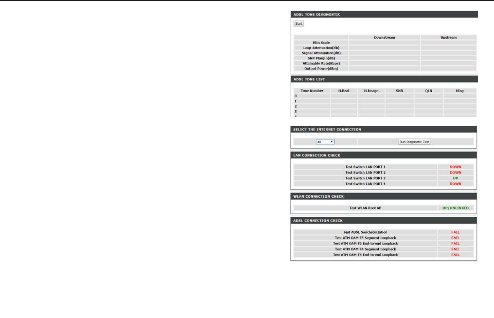
ADSL Test
Choose MAINTAINANCE > Diagnosis > ADSL Test. The page shown in the
right figure appears. In this page, you can test your DSL connection by clicking
Start.
.
DIAGNOSTIC Test
Choose MAINTAINANCE > Diagnosis > Diag Test. The page shown in the right
figure appears. In this page, you can test the bit error rate.
The DSL Router is capable of testing your DSL connection. The individual tests
are listed below. If a test displays a fail status, click "Run Diagnostic Test" button
again to make sure the fail status is consistent.
Section 4 – Troubleshooting
D-Link DSL-2740E User Manual
50
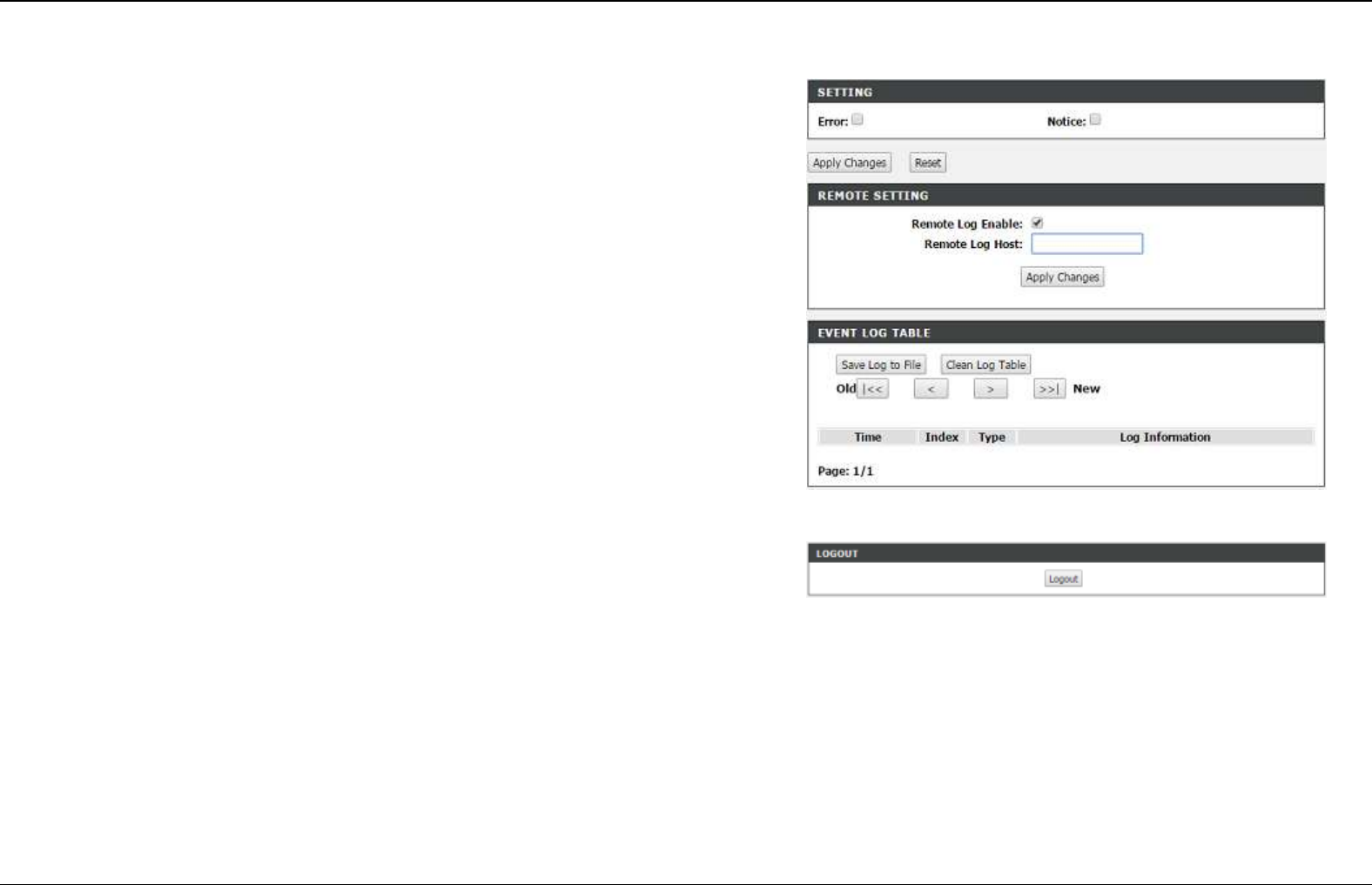
System Log
Choose MAINTAINANCE > System Log. The System Log page shown in the
right figure appears.
This page displays event log data in the chronological manner. You can read the
event log from the local host or send it to a system log server. Available event
severity levels are as follows: Emergency, Alert, Critical, Error, Warning, Notice,
Informational and Debugging. In this page, you can enable or disable the system
log function.
To log the events, take the following steps.
Step 1 Select Settings check box to configure log level.
Step 2 Click Apply Changes to apply the settings.
Step 3 Check Remote Log Enable and configure remote systlog server IP
address to enable remote log.
Step 4 Click Apply Changes to apply the settings.
Logout
Choose MANAGEMENT > Logout. The page shown in the right figure appears.
In this page, you can log out of the configuration page.
Status
In the main interface, click Status tab to enter the Status menu. The submenus are Device Info, Wireless Clients, DHCP clients, ADSL Driver,
Statistics, Route Info . You can view the system information and monitor performance.
Help
In the main interface, click Help tab to enter the Help menu. This section provides detailed configuration information for the device. Click a wanted
link to view corresponding information.

Section 4 - Troubleshooting
D-Link DSL-2740E User Manual
51
Troubleshooting
This chapter provides solutions to problems that might occur during the installation and operation of the DSL-2740E. Read the following descriptions
if you are having problems. (The examples below are illustrated in Windows® XP. If you have a different operating system, the screenshots on your
computer will look similar to the following examples.)
1. How do I configure my DSL-2740E Router without the CD-ROM?
Step 1 Connect your PC to the Router using an Ethernet cable.
Step 2 Open a web browser and enter the address http://192.168.1.1
Step 3 The default username is ‘admin’ and the default password is ‘admin’.
Step 4 If you have changed the password and cannot remember it, you will need to reset the Router to the factory default setting (see question 2),
which will set the password back to ‘admin’.
2. How do I reset my Router to the factory default settings?
Step 1 Ensure the Router is powered on.
Step 2 Press and hold the reset button on the back of the device for approximately 1 second.
Step 3 This process should take around 1 to 2 minutes.
Note:
Resetting the Router to the factory default settings will erase the current configuration settings.
3. What can I do if my Router is not working correctly?
There are a few quick steps you can take to try and resolve any issues:
Step 1 Follow the directions in Question 2 to reset the Router.
Step 2 Check that all the cables are firmly connected at both ends.
Step 3 Check the LEDs on the front of the Router. The Power indicator should be on, the Status indicator should flash, and the DSL and LAN

Section 4 – Troubleshooting
D-Link DSL-2740E User Manual
52
indicators should be on as well.
Step 4 Please ensure that the settings in the Web-based configuration manager, e.g. ISP username and password, are the same as the settings
that have been provided by your ISP.
4. Why can’t I get an Internet connection?
For ADSL ISP users, please contact your ISP to make sure the service has been enabled/connected by your ISP and that your ISP username and
password are correct.
5. What can I do if my Router can’t be detected by running the installation CD?
Step 1 Ensure the Router is powered on.
Step 2 Check that all the cables are firmly connected at both ends and all LEDs are working correctly.
Step 3 Ensure only one network interface card on your PC is activated.
Step 4 Click on Start > Control Panel > Security Center to disable the firewall.
Note:
There is a potential security issue if the firewall is disabled on your PC. Please remember to turn it back on once you have finished the whole
installation procedure. This will enable you to surf the Internet without any problems.
Appendix A – Networking Basic
D-Link DSL-2740E User Manual
53
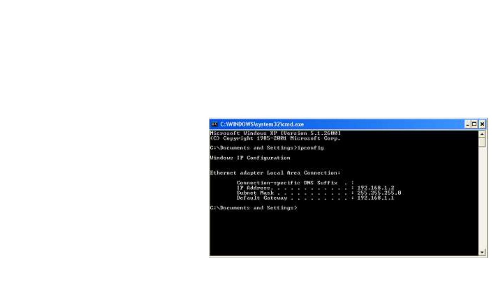
Networking Basics
Check Your IP Address
After you install your new D-Link adapter, by default, the TCP/IP settings should be set to obtain an IP address from a DHCP server (i.e. wireless
router) automatically. To verify your IP address, please follow the steps below.
Click on Start
>
Run. In the run box type cmd and click on the OK button.
At the prompt, type ipconfig and press Enter.
This will display the IP address, subnet mask and the default
gateway of your adapter.
If the address is 0.0.0.0, check your adapter installation,
security settings and the settings on your router. Some
firewall software programs may block a DHCP request on
newly installed adapters.
If you are connecting to a wireless network at a hotspot (e.g.
hotel, coffee shop, airport), please contact an employee or
administrator to verify their wireless network settings.

Appendix B –Statically Assigning an IP Address
D-Link DSL-2740E User Manual
54
Statically Assigning an IP Address
If you are not using a DHCP capable gateway/router, or you need to assign a static IP address, please follow the steps below:
Step 1
Windows® XP - Click on Start > Control Panel > Network Connections.
Windows® 2000 - From the desktop, right-click on the My Network Places > Properties.
Step 2
Right-click on the Local Area Connection which represents your network adapter and select the Properties button.
Step 3
Highlight Internet Protocol (TCP/IP) and click on the Properties button.
Step 4
Click on the Use the following IP address and enter an IP address that is on the same subnet as
your network or the LAN IP address on your router.
Example: If the router’s LAN IP address is 192.168.1.1, make your IP address 192.168.1.X where X
is a number between 2 and 254. Make sure that the number you choose is not in use on the
network. Set the Default Gateway to be the same as the LAN IP address of your router
(192.168.1.1).
Set the Primary DNS to be the same as the LAN IP address of your router (192.168.1.1). The
Secondary DNS is not needed or you may enter a DNS server from your ISP.
Step 5
Click on the OK button twice to save your settings.

Appendix C – Technical Specifications
D-Link DSL-2740E User Manual
55
Technical Specifications
ADSL
Standards
ANSI T1.413 Issue 2
ITU G.992.1 (G.dmt) AnnexA
ITU G.992.2 (G.lite) Annex A
ITU G.994.1 (G.hs)
ITU G.992.5 Annex A
ADSL2
Standards
ITU G.992.3 (G.dmt.bis) Annex A, L, M
ITU G.992.4 (G.lite.bis) Annex A, L, M
ADSL2+ Standards
ITU G.992.5 (ADSL2+) Annex A, L, M
Protocols
Data
Transfer
Rate
G.dmt full rate downstream: up to 8 Mbps / upstream: up to 1
Mbps
G.lite: ADSL downstream up to 1.5 Mbps / upstream up to 512
Kbps
G.dmt.bis full rate downstream: up to 12 Mbps / upstream: up to
12 Mbps
ADSL full rate downstream: up to 24 Mbps / upstream: up to 1
Mbps
Media
Interface
ADSL interface: RJ-11 connector for connection to 24/26 AWG
twisted pair telephone line
LAN interface: RJ-45 port for 10/100BASE-T Ethernet connection
TCP/UDP
ARP
RARP
ICMP
RFC1058 RIP v1
RFC1213 SNMP v1 & v2c
RFC1334 PAP
RFC1389 RIP v2
RFC1577 Classical IP over
ATM
RFC1483/2684
Multiprotocol
Encapsulation over ATM
Adaptation Layer 5 (AAL5)
RFC1661 Point to Point
Protocol
RFC1994 CHAP
RFC2131 DHCP Client /
DHCP Server
RFC2364 PPP over ATM
RFC2516 PPP over
Ethernet