D Link SL2740RA1 WIRELESS G ADSL2+MODEM ROUTER User Manual User Man1
D Link Corporation WIRELESS G ADSL2+MODEM ROUTER User Man1
D Link >
Contents
- 1. User Man1
- 2. User Man2
User Man1
FCC Notices
This device complies with Part 15 of the FCC Rules. Operation is subject to the following two conditions: (1) this device may not cause harmful
interference, and (2) this device must accept any interference received, including interference that may cause undesired operation.
CAUTION: Change or modification not expressly approved by the party responsible for compliance could void the user’s authority to operate this equipment.
This equipment has been tested and found to comply with the limits for a Class B digital device, pursuant to Part 15 of the FCC Rules. These limits
are designed to provide reasonable protection against harmful interference in a residential installation. This equipment generates, uses and can
radiate radio frequency energy and, if not installed and used in accordance with the instructions, may cause harmful interference to radio
communications. However, there is no guarantee that interference will not occur in a particular installation. If this equipment does cause harmful
interference to radio or television reception, which can be determined by turning the equipment off and on, the user is encouraged to try to correct
the interference by one or more of the following measures:
--Reorient or relocate the receiving antenna.
--Increase the separation between the equipment and receiver.
--Connect the equipment into an outlet on a circuit different from that to which the receiver is connected.
--Consult the dealer or an experienced radio/TV technician for help.
CAUTION: Any changes or modifications not expressly approved by the grantee of this device could void the user's authority to operate the equipment.
RF exposure warning:
The equipment complies with FCC RF exposure limits set forth for an uncontrolled environment. The equipment must not be co-located or operating
in conjunction with any other antenna or transmitter.

D-Link DSL-2740R User Manual i
FCC
Federal Communication Commission Interference Statement
This equipment has been tested and found to comply with the limits for a Class B digital device, pursuant to Part 15 of the FCC Rules. These limits
are designed to provide reasonable protection against harmful interference in a residential installation. This equipment generates, uses and can
radiate radio frequency energy and, if not installed and used in accordance with the instructions, may cause harmful interference to radio
communications. However, there is no guarantee that interference will not occur in a particular installation. If this equipment does cause harmful
interference to radio or television reception, which can be determined by turning the equipment off and on, the user is encouraged to try to correct
the interference by one of the following measures:
− Reorient or relocate the receiving antenna.
− Increase the separation between the equipment and receiver.
− Connect the equipment into an outlet on a circuit different from that to which the receiver is connected.
− Consult the dealer or an experienced radio/TV technician for help.
This device complies with Part 15 of the FCC Rules. Operation is subject to the following two conditions: (1) This device may not cause harmful
interference, and (2) this device must accept any interference received, including interference that may cause undesired operation.
FCC Caution: Any changes or modifications not expressly approved by the party responsible for compliance could void the user's authority to
operate this equipment.
IMPORTANT NOTE:
FCC Radiation Exposure Statement:
This equipment complies with FCC radiation exposure limits set forth for an uncontrolled environment. This equipment should be installed and
operated with minimum distance 20cm between the radiator & your body.
This transmitter must not be co-located or operating in conjunction with any other antenna or transmitter.
IEEE 802.11b or 802.11g operation of this product in the U.S.A. is firmware-limited to channels 1 through 11.

Table of Contents
D-Link DSL-2740R User Manual ii
Table of Contents
PACKAGE CONTENTS .......................................................................................... 1
SYSTEM REQUIREMENTS ..................................................................................... 1
FEATURES .......................................................................................................... 2
HARDWARE OVERVIEW........................................................................................ 3
Connections ................................................................................................. 3
LEDs............................................................................................................. 4
INSTALLATION .................................................................................................... 6
BEFORE YOU BEGIN............................................................................................ 6
INSTALLATION NOTES .......................................................................................... 6
DEVICE INSTALLATION ....................................................................................... 10
Power on Router .........................................................................................11
Factory Reset Button...................................................................................11
Network Connections ................................................................................. 12
SETUP ................................................................................................................ 13
Web-based Configuration Utility................................................................. 13
QUICK SETUP ................................................................................................... 14
ADSL SETUP ................................................................................................... 21
PPPoE/PPPoA ........................................................................................... 22
Dynamic IP Address ................................................................................... 23
Static IP Address ........................................................................................ 24
Bridge Mode ............................................................................................... 25
WIRELESS SETUP ............................................................................................. 26
WEP ........................................................................................................... 27
WPA-Personal ............................................................................................ 28
LAN SETUP...................................................................................................... 29
Use the Router for DHCP........................................................................... 30
Disable the DHCP Server........................................................................... 30
TIME AND DATE ................................................................................................. 31
ADVANCED ........................................................................................................ 32
PORT FORWARDING .......................................................................................... 32
QOS SETUP ..................................................................................................... 33
Wireless QoS ............................................................................................. 34
LAN QoS .................................................................................................... 35
OUTBOUND FILTER............................................................................................ 36
INBOUND FILTER................................................................................................ 37
DNS SETUP ..................................................................................................... 38
VLAN............................................................................................................... 40
FIREWALL & DMZ ............................................................................................. 41
ADVANCED ADSL.............................................................................................. 42
ADVANCED WIRELESS ....................................................................................... 43
ADVANCED LAN ................................................................................................ 44
REMOTE MANAGEMENT ..................................................................................... 45
NETWORK TOOLS .............................................................................................. 46
MAINTENANCE.................................................................................................. 47
PASSWORD ....................................................................................................... 47
SAVE/RESTORE SETTINGS ................................................................................. 48
FIRMWARE UPDATE ........................................................................................... 49
DIAGNOSTICS.................................................................................................... 50
SYSTEM LOG..................................................................................................... 51
STATUS............................................................................................................... 52
DEVICE INFO ..................................................................................................... 52
CONNECTED CLIENTS ........................................................................................ 53
STATISTICS ....................................................................................................... 54
HELP ................................................................................................................... 55
TROUBLESHOOTING........................................................................................ 56
NETWORKING BASICS..................................................................................... 58
CHECK YOUR IP ADDRESS................................................................................. 58
STATICALLY ASSIGN AN IP ADDRESS .................................................................. 59
TECHNICAL SPECIFICATIONS......................................................................... 60

Section 1 - Product Overview
D-Link DSL-2740R User Manual 1
Package Contents
• DSL-2740R Wireless N ADSL2+ Modem Router
• Power Adapter
• CD-ROM with User Manual
• One twisted-pair telephone cable used for ADSL connection
• One straight-through Ethernet cable
• One Quick Installation Guide
Warning: The Router must be used with the power adapter included with the device.
System Requirements
• ADSL Internet service
• Computer with:
• 200MHz Processor
• 64MB Memory
• CD-ROM Drive
• Ethernet Adapter with TCP/IP Protocol Installed
• Internet Explorer v6 or later, FireFox v1.5, or Safari 1.3 or above
• Windows 2000/XP/Vista
• D-Link Click'n Connect Utility

Section 1 - Product Overview
D-Link DSL-2740R User Manual 2
11
Features
• PPP (Point-to-Point Protocol) Security – The Router supports PAP (Password Authentication Protocol) and CHAP (Challenge Handshake
Authentication Protocol) for PPP connections. The Router also supports MSCHAP.
• DHCP Support – Dynamic Host Configuration Protocol automatically and dynamically assigns all LAN IP settings to each host on your
network. This eliminates the need to reconfigure every host whenever changes in network topology occur.
• Network Address Translation (NAT) – For small office environments, the Router allows multiple users on the LAN to access the Internet
concurrently through a single Internet account. This provides Internet access to everyone in the office for the price of a single user. NAT
improves network security in effect by hiding the private network behind one global and visible IP address. NAT address mapping can also be
used to link two IP domains via a LAN-to-LAN connection.
• TCP/IP (Transfer Control Protocol/Internet Protocol) – The Router supports TCP/IP protocol, the language used for the Internet. It is
compatible with access servers manufactured by major vendors.
• RIP-1/RIP-2 – The Router supports both RIP-1 and RIP-2 exchanges with other routers. Using both versions lets the Router to communicate
with all RIP enabled devices.
• Static Routing – This allows you to select a data path to a particular network destination that will remain in the routing table and never “age
out”. If you wish to define a specific route that will always be used for data traffic from your LAN to a specific destination within your LAN (for
example to another router or a server) or outside your network (to an ISP defined default gateway for instance).
• Default Routing – This allows you to choose a default path for incoming data packets for which the destination address is unknown. This is
particularly useful when/if the Router functions as the sole connection to the Internet.
• ATM (Asynchronous Transfer Mode) – The Router supports Bridged Ethernet over ATM (RFC1483), IP over ATM (RFC1577), and PPP
over ATM (RFC 2364).
• Precise ATM Traffic Shaping – Traffic shaping is a method of controlling the flow rate of ATM data cells. This function helps to establish the
Quality of Service for ATM data transfer.
• High Performance – Very high rates of data transfer are possible with the Router. Up to 8 Mbps downstream bit rate using the G.dmt
standard.
• Full Network Management – The Router incorporates SNMP (Simple Network Management Protocol) support for web-based management
and text-based network management via an RS-232 or Telnet connection.
• Telnet Connection – The Telnet enables a network manager to access the Router’s management software remotely.
• Easy Installation – The Router uses a web-based graphical user interface program for convenient management access and easy set up.
Any common web browser software can be used to manage the Router.
Section 1 - Product Overview
D-Link DSL-2740R User Manual 3
Hardware Overview
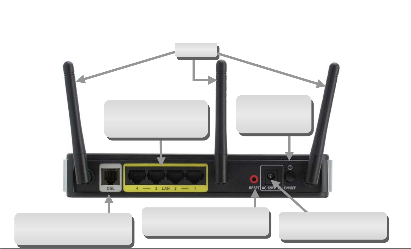
Connections
Power Insert
Use the adapter shipped with the
Router to connect to
p
ower source.
Power Button
Push in to power-on
the Router. Push again
to power-off the
Router.
Ethernet Ports
Use the Ethernet ports to
connect the Router to a compute
r
or an Ethernet LAN.
ADSL Port
Use the ADSL cable to connect to the
your telephone line (RJ-11 port).
Reset Button
To manually reset, depress button with
the power on for at least seven seconds.
Antennas
Section 1 - Product Overview
D-Link DSL-2740R User Manual 4
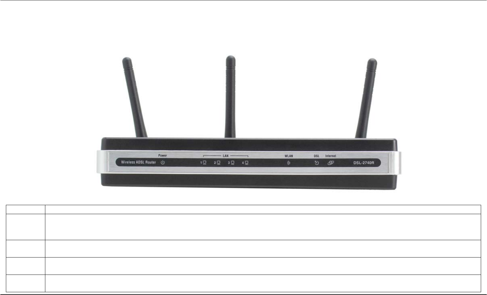
Hardware Overview
LEDs
LED Description
Power A steady green light indicates the unit is powered on. When the device is powered off this remains dark. Lights steady green during
power on self-test (POST). Once the connection status has been settled, the light will blink green. If the indicator lights steady red
after the POST, the system has failed and the device should be rebooted.
LAN A solid green light indicates a valid link on startup. This light will blink when there is activity currently passing through the Ethernet
port.
WLAN A solid green light indicates a valid link on startup. This light will blink when there is activity currently passing through the Wireless
LAN.
DSL A steady green light indicates a valid ADSL connection. This will light after the ADSL negotiation process has been settled. A
blinking green light indicates activity on the WAN (ADSL) interface.
Section 1 - Product Overview
D-Link DSL-2740R User Manual 5
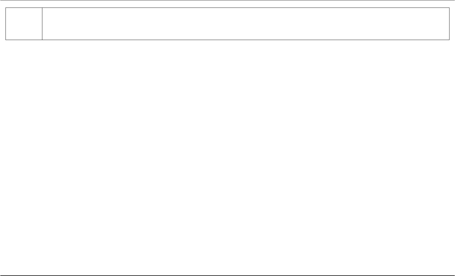
Internet A solid green light indicates the WAN IP address from IPCP or DHCP and DSL is up or a static IP address is configured and PPP
negotiation has been successfully completed. If the indicator blinks green, this means the Router is active. If the Router power is
off, this remains dark. A solid red light indicates there is no DHCP response, no PPPoE response, PPPoE authentication has failed,
and/or there is no IP.

Section 2 – Installation
D-Link DSL-2740R User Manual 6
Installation
This section will walk you through the installation process. Placement of the Router is very important. Do not place the Router in an enclosed area
such as a closet, cabinet, or in the attic or garage.
Before You Begin
Please read and make sure you understand all the prerequisites for proper installation of your new Router. Have all the necessary information and
equipment on hand before beginning the installation.
Installation Notes
In order to establish a connection to the Internet it will be necessary to provide information to the Router that will be stored in its memory. For some
users, only their account information (Username and Password) is required. For others, various parameters that control and define the Internet
connection will be required. You can print out the two pages below and use the tables to list this information. This way you have a hard copy of all
the information needed to setup the Router. If it is necessary to reconfigure the device, all the necessary information can be easily accessed. Be
sure to keep this information safe and private.
Low Pass Filters
Since ADSL and telephone services share the same copper wiring to carry their respective signals, a filtering mechanism may be necessary to
avoid mutual interference. A low pass filter device can be installed for each telephone that shares the line with the ADSL line. These filters are easy
to install passive devices that connect to the ADSL device and/or telephone using standard telephone cable. Ask your service provider for more
information about the use of low pass filters with your installation.
Operating Systems
The DSL-2740R uses an HTML-based web interface for setup and management. The Web configuration manager may be accessed using any
operating system capable of running web browser software, including Windows 98 SE, Windows ME, Windows 2000, Windows XP, and Windows
Vista.

Section 2 – Installation
D-Link DSL-2740R User Manual 7
Web Browser
Any common Web browser can be used to configure the Router using the Web configuration management software. The program is designed to
work best with more recently released browsers such as Opera, Microsoft Internet Explorer® version 6.0, Netscape Navigator® version 6.2.3, or
later versions. The Web browser must have JavaScript enabled. JavaScript is enabled by default on many browsers. Make sure JavaScript has not
been disabled by other software (such as virus protection or web user security packages) that may be running on your computer.
Ethernet Port (NIC Adapter)
Any computer that uses the Router must be able to connect to it through the Ethernet port on the Router. This connection is an Ethernet connection
and therefore requires that your computer be equipped with an Ethernet port as well. Most notebook computers are now sold with an Ethernet port
already installed. Likewise, most fully assembled desktop computers come with an Ethernet NIC adapter as standard equipment. If your computer
does not have an Ethernet port, you must install an Ethernet NIC adapter before you can use the Router. If you must install an adapter, follow the
installation instructions that come with the Ethernet NIC adapter.
Additional Software
It may be necessary to install software on your computer that enables the computer to access the Internet. Additional software must be installed if
you are using the device a simple bridge. For a bridged connection, the information needed to make and maintain the Internet connection is stored
on another computer or gateway device, not in the Router itself.
If your ADSL service is delivered through a PPPoE or PPPoA connection, the information needed to establish and maintain the Internet connection
can be stored in the Router. In this case, it is not necessary to install software on your computer. It may however be necessary to change some
settings in the device, including account information used to identify and verify the connection.
All connections to the Internet require a unique global IP address. For bridged connections, the global IP settings must reside in a TCP/IP enabled
device on the LAN side of the bridge, such as a PC, a server, a gateway device such as a router or similar firewall hardware. The IP address can be
assigned in a number of ways. Your network service provider will give you instructions about any additional connection software or NIC
configuration that may be required.

Section 2 – Installation
D-Link DSL-2740R User Manual 8
Information you will need from your ADSL service
provider
Username
This is the Username used to log on to your ADSL service provider’s network. Your ADSL service provider uses this to identify your account.
Password
This is the Password used, in conjunction with the Username above, to log on to your ADSL service provider’s network. This is used to verify the
identity of your account.
WAN Setting / Connection Type
These settings describe the method your ADSL service provider uses to transport data between the Internet and your computer. Most users will use
the default settings. You may need to specify one of the following WAN Setting and Connection Type configurations (Connection Type settings listed
in parenthesis):
• PPPoE/PPoA (PPPoE LLC, PPPoE VC-Mux, PPPoA LLC, or PPPoA VC-Mux)
• Dynamic IP Address (1483 Bridged IP LLC or 1483 Bridged IP VC-Mux)
• Static IP Address (Bridged IP LLC, 1483 Bridged IP VC Mux, 1483 Routed IP LLC, 1483 Routed IP VC-Mux)
• Bridge Mode (1483 Bridged IP LLC or 1483 Bridged IP VC Mux)
Modulation Type
ADSL uses various standardized modulation techniques to transmit data over the allotted signal frequencies. Some users may need to change the
type of modulation used for their service. The default DSL modulation (Autosense) used for the Router automatically detects all types of ADSL,
ADSL2, and ADSL2+ modulation.
Security Protocol
This is the method your ADSL service provider will use to verify your Username and Password when you log on to their network. Your Router
supports the PAP and CHAP protocols.

Section 2 – Installation
D-Link DSL-2740R User Manual 9
VPI
Most users will not be required to change this setting. The Virtual Path Identifier (VPI) is used in conjunction with the Virtual Channel Identifier (VCI)
to identify the data path between your ADSL service provider’s network and your computer. If you are setting up the Router for multiple virtual
connections, you will need to configure the VPI and VCI as instructed by your ADSL service provider for the additional connections. This setting can
be changed in the WAN Settings window of the web management interface.
VCI
Most users will not be required to change this setting. The Virtual Channel Identifier (VCI) used in conjunction with the VPI to identify the data path
between your ADSL service provider’s network and your computer. If you are setting up the Router for multiple virtual connections, you will need to
configure the VPI and VCI as instructed by your ADSL service provider for the additional connections. This setting can be changed in the WAN
Settings window of the web management interface.
Information you will need about DSL-2740R
Username
This is the Username needed access the Router’s management interface. When you attempt to connect to the device through a web browser you
will be prompted to enter this Username. The default Username for the Router is “admin.” The user cannot change this.
Password
This is the Password you will be prompted to enter when you access the Router’s management interface. The default Password is “admin.” The
user may change this.
LAN IP addresses for the DSL-2740R
This is the IP address you will enter into the Address field of your web browser to access the Router’s configuration graphical user interface (GUI)
using a web browser. The default IP address is 192.168.1.1. This may be changed to suit any IP address scheme the user desires. This address will
be the base IP address used for DHCP service on the LAN when DHCP is enabled.
LAN Subnet Mask for the DSL-2740R
This is the subnet mask used by the DSL-2740R, and will be used throughout your LAN. The default subnet mask is 255.255.255.0. This can be
changed later.

Section 2 – Installation
D-Link DSL-2740R User Manual 10
Information you will need about your LAN or computer:
Ethernet NIC
If your computer has an Ethernet NIC, you can connect the DSL-2740R to this Ethernet port using an Ethernet cable. You can also use the Ethernet
ports on the DSL-2740R to connect to other computer or Ethernet devices.
DHCP Client status
Your Router is configured, by default, to be a DHCP server. This means that it can assign an IP address, subnet mask, and a default gateway
address to computers on your LAN. The default range of IP addresses the DSL-2740R will assign are from 192.168.1.2 to 192.168.1.254. Your
computer (or computers) needs to be configured to obtain an IP address automatically (that is, they need to be configured as DHCP clients.)
It is recommended that your collect and record this information here, or in some other secure place, in case you have to re-configure your ADSL
connection in the future.
Once you have the above information, you are ready to setup and configure your DSL-2740R.
Device Installation
The DSL-2740R connects two separate physical interfaces, an ADSL (WAN) and an Ethernet (LAN) interface. Place the Router in a location where
it can be connected to the various devices as well as to a power source. The Router should not be located where it will be exposed to moisture or
excessive heat. Make sure the cables and power cord are placed safely out of the way so they do not create a tripping hazard. As with any electrical
appliance, observe common sense safety procedures.
The Router can be placed on a shelf or desktop, ideally you should be able to see the LED indicators on the front if you need to view them for
troubleshooting.

Section 2 – Installation
D-Link DSL-2740R User Manual 11
Power on Router
The Router must be used with the power adapter included with the device.
1. Insert the AC Power Adapter cord into the power receptacle located on the rear panel of the Router and plug the adapter into a suitable nearby
power source.
2. Depress the Power button into the on position. You should see the Power LED indicator light up and remain lit. The Status LED should light solid
green and begin to blink after a few seconds.
3. If the Ethernet port is connected to a working device, check the Ethernet Link/Act LED indicators to make sure the connection is valid. The
Router will attempt to establish the ADSL connection, if the ADSL line is connected and the Router is properly configured this should light up
after several seconds. If this is the first time installing the device, some settings may need to be changed before the Router can establish a
connection.
Factory Reset Button
The Router may be reset to the original factory default settings by using a ballpoint or paperclip to gently push down the reset button in the following
sequence:
1. Ensure the Router is powered on.
2. Press and hold the reset button on the back of the device for approximately 5 to 8 seconds.
3. This process should take around 1 to 2 minutes.
Remember that this will wipe out any settings stored in flash memory including user account information and LAN IP settings. The device settings
will be restored to the factory default IP address 192.168.1.1 and the subnet mask is 255.255.255.0, the default management Username is “admin”
and the default Password is “admin.”

Section 2 – Installation
D-Link DSL-2740R User Manual 12
Network Connections
Connect ADSL Line
Use the ADSL cable included with the Router to connect it to a telephone wall socket or receptacle. Plug one end of the cable into the ADSL port
(RJ-11 receptacle) on the rear panel of the Router and insert the other end into the RJ-11 wall socket. If you are using a low pass filter device, follow
the instructions included with the device or given to you by your service provider. The ADSL connection represents the WAN interface, the
connection to the Internet. It is the physical link to the service provider’s network backbone and ultimately to the Internet.
Connect Router to Ethernet
The Router may be connected to a single computer or Ethernet device through the 10BASE-TX Ethernet port on the rear panel. Any connection to
an Ethernet concentrating device such as a switch or hub must operate at a speed of 10/100 Mbps only. When connecting the Router to any
Ethernet device that is capable of operating at speeds higher than 10Mbps, be sure that the device has auto-negotiation (NWay) enabled for the
connecting port. Use standard twisted-pair cable with RJ-45 connectors. The RJ-45 port on the Router is a crossed port (MDI-X). Follow standard
Ethernet guidelines when deciding what type of cable to use to make this connection. When connecting the Router directly to a PC or server use a
normal straight-through cable. You should use a crossed cable when connecting the Router to a normal (MDI-X) port on a switch or hub. Use a
normal straight-through cable when connecting it to an uplink (MDI-II) port on a hub or switch. The rules governing Ethernet cable lengths apply to
the LAN to Router connection. Be sure that the cable connecting the LAN to the Router does not exceed 100 meters.
Hub or Switch to Router Connection
Connect the Router to an uplink port (MDI-II) on an Ethernet hub or switch with a straight-through cable. If you wish to reserve the uplink port on the
switch or hub for another device, connect to any on the other MDI-X ports (1x, 2x, etc.) with a crossed cable.
Computer to Router Connection
You can connect the Router directly to a 10/100BASE-TX Ethernet adapter card (NIC) installed on a PC using the Ethernet cable provided.
Section 3 – Configuration
D-Link DSL-2740R User Manual 13
Setup
This section will show you how to set up and configure your new D-Link Router using the Web-based configuration utility.
Web-based Configuration Utility
Connect to the Router
To configure the WAN connection used by the Router it is first necessary to communicate with the Router through its management interface, which
is HTML-based and can be accessed using a web browser. The easiest way to make sure your computer has the correct IP settings is to configure
it to use the DHCP server in the Router. The next section describes how to change the IP configuration for a computer running a Windows operating
system to be a DHCP client.
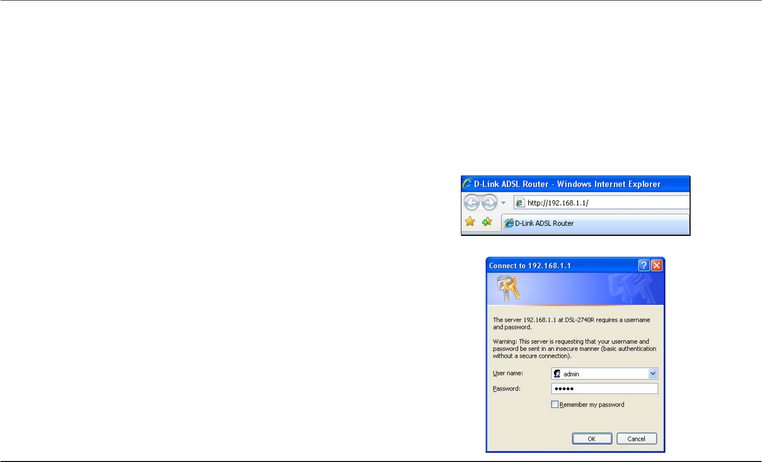
To access the configuration utility, open a web-browser such as Internet
Explorer and enter the IP address of the router (192.168.1.1).
Type “admin” for the User Name and “admin” in the Password field. If
you get a Page Cannot be Displayed error, please refer to the
Troubleshooting section for assistance.
Section 3 – Configuration
D-Link DSL-2740R User Manual 14
Quick Setup
This chapter is concerned with using your computer to configure the WAN connection. The following chapter describes the various windows used to
configure and monitor the Router including how to change IP settings and DHCP server setup.
QUICK SETUP
Click the Setup Wizard link in the middle of the top of the window of the
Router’s opening page to launch a series of setup windows.
Section 3 – Configuration
D-Link DSL-2740R User Manual 15
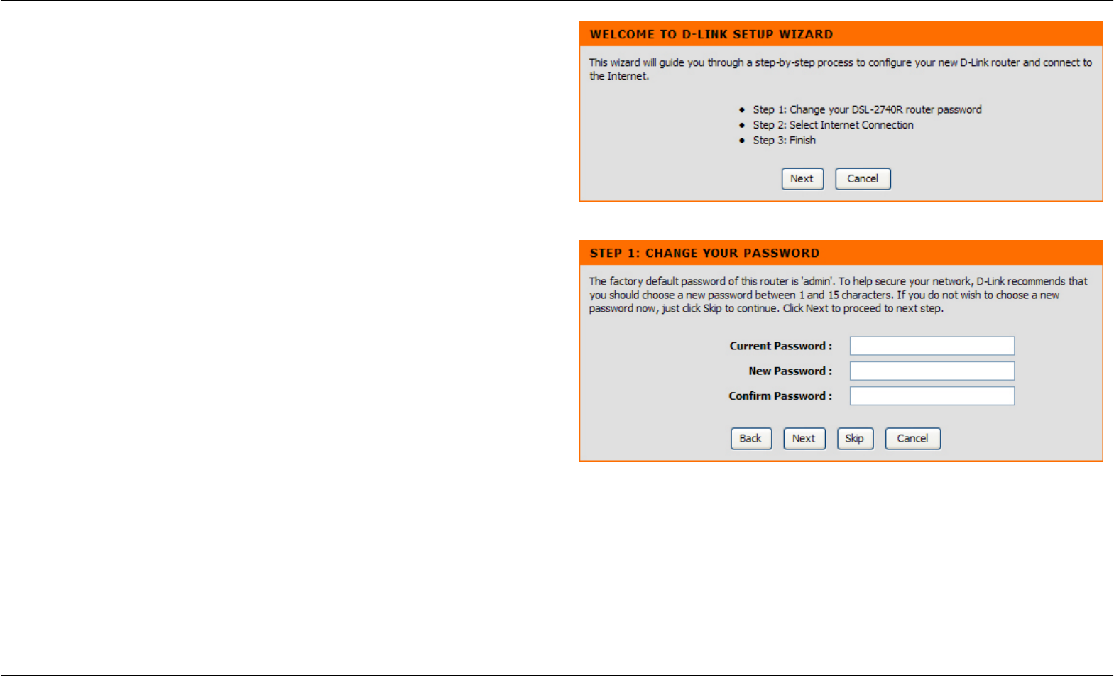
QUICK SETUP – OPENING WINDOW
The first window of the Setup Wizard lists the basic steps in the process.
These steps are as follows:
1. Change the Router password.
2. Configure the connection to the Internet.
3. Save the new configuration settings and reboot the system.
QUICK SETUP – CHANGE YOUR ROUTER PASSWORD
This window of the Setup Wizard is used to change the Router
password. D-Link recommends to help secure your network, the user
change the Current Password from the factory default “admin.” The New
Password should be between 1 and 15 alphanumeric characters. Once
you have filled out the fields in this window, including re-typing the new
password in the Confirm Password field, click the Next button to
continue.
If you do not want to change the password, click the Skip button to
proceed to the next step.
Section 3 – Configuration
D-Link DSL-2740R User Manual 16
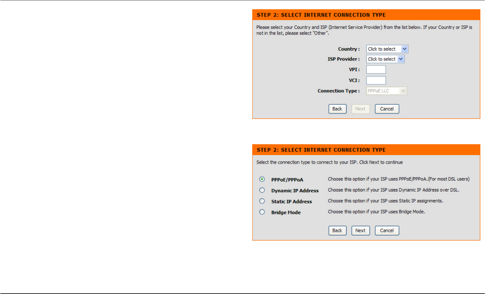
QUICK SETUP – SELECT THE INTERNET CONNECTION TYPE
Now use the drop-down menus to select the Country, ISP Provider, and
Connection Type used for the Internet connection, and enter VPI and
VCI values if applicable. Your ISP has given this information to you—any
information that is not required for your provider will automatically be
grayed out in this window and subsequent Quick Setup windows.
The Connection Type options are 1483 Bridged IP LLC, 1483 Bridged I
P
VC-Mux, 1483 Routed IP LLC, 1483 Routed IP VC-Mux, PPPoE LLC,
PPPoE VC-Mux, PPPoA LLC, and PPPoA VC-Mux.
Click the Next button when you are finished to proceed to the next Setup
Wizard window.
QUICK SETUP – SELECT THE INTERNET CONNECTION TYPE
If the following Setup Wizard window appears, please select the
connection type used by your ISP and then click the Next button. Most
users, however, will be sent directly to a Setup Wizard window for their
specific Internet connection type based on the information entered in the
previous Setup Wizard window.
Section 3 – Configuration
D-Link DSL-2740R User Manual 17
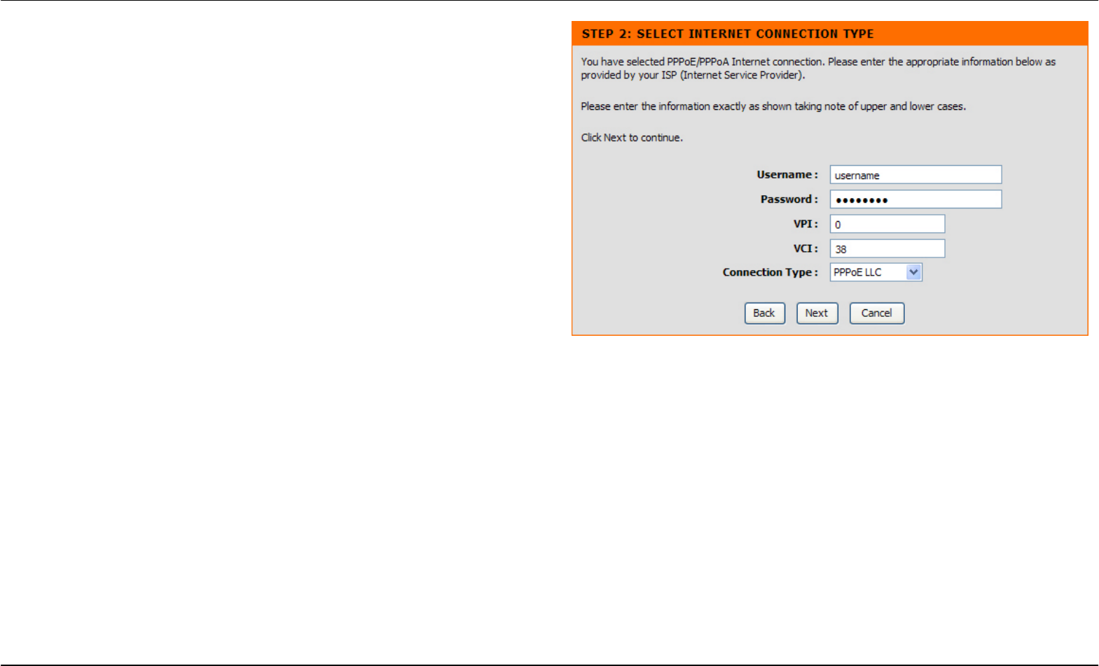
QUICK SETUP – PPPOE/PPPOA CONFIGURATION
Type in the User Name and Password used to identify and verify your
account to the ISP. If you are instructed to change the VPI or VCI
number, type in the correct setting in the available entry fields. Most
users will not need to change these settings. The Internet connection
cannot function if these values are incorrect.
Some users may have to adjust the Connection Type from the
drop-down menu at the bottom of this Setup Wizard window. The
available connection and encapsulation types are PPPoE LLC, PPoE
VC-Mux, PPPoA LLC, and PPPoA VC-Mux.
Click Next to go to the last Setup Wizard window.
Section 3 – Configuration
D-Link DSL-2740R User Manual 18
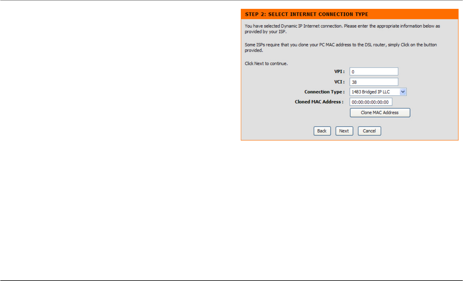
QUICK SETUP – DYNAMIC IP CONFIGURATION
If you are instructed to change the VPI or VCI numbers, type in the
correct setting in the available entry fields. The Internet connection
cannot function if these values are incorrect. Select the specific
Connection Type from the drop-down menu. The available connection
and encapsulation types are 1483 Bridged IPLLC and 1483 Bridged IP
VC-Mux. You may want to copy the MAC address of your Ethernet
adapter to the Router. Some ISPs record the unique MAC address of
your computer’s Ethernet adapter when you first access their network.
This can prevent the Router (which has a different MAC address) from
being allowed access to the ISPs network (and the Internet). To clone
the MAC address of your computer’s Ethernet adapter, click the Clone
MAC Address button. This will copy the information to a file used by the
Router to present to the ISP’s server used for DHCP.
Click Next to
g
o to the last Setu
p
Wizard window.
Section 3 – Configuration
D-Link DSL-2740R User Manual 19
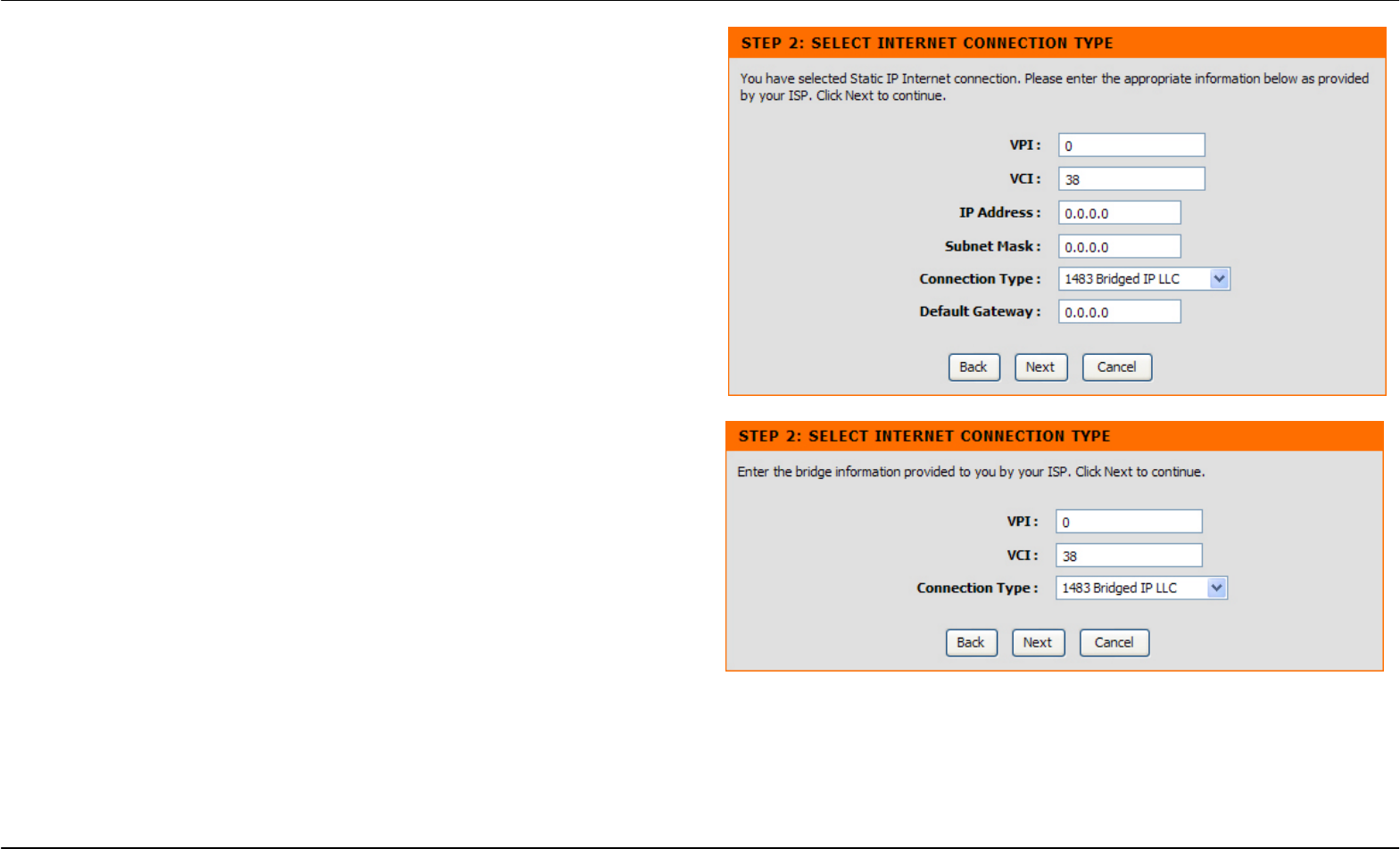
QUICK SETUP – STATIC IP CONFIGURATION
Enter values for VPI, VCI, IP Address, Subnet Mask, Default Gateway IP
address, Preferred DNS Server IP address, and Alternate DNS Server
IP address as instructed by your ISP. The Internet connection cannot
function if these values are incorrect.
Select the specific Connection Type from the drop-down menu. The
available connection and encapsulation types are 1483 Bridged IP LLC,
1483 Bridged IP VC-Mux, 1483 Routed IP LLC, and 1483 Routed IP
VC-Mux.
Click Next to go to the last Setup Wizard window.
QUICK SETUP – BRIDGE MODE CONFIGURATION
If you are instructed to change the VPI or VCI numbers, type in the
correct setting in the available entry fields. The Internet connection
cannot function if these values are incorrect.
Select the specific Connection Type from the drop-down menu. The
available connection and encapsulation types are 1483 Bridged IP LLC
and 1483 Bridged IP VC-Mux.
Click Next to go to the last Setup Wizard window.
Section 3 – Configuration
D-Link DSL-2740R User Manual 20
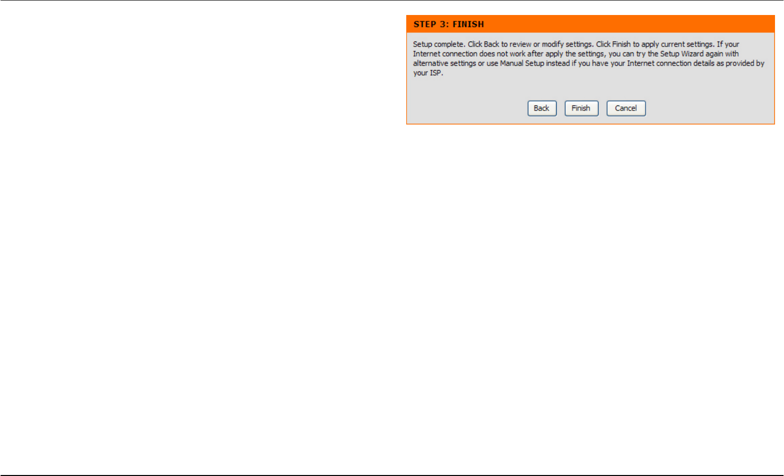
QUICK SETUP – FINISH
Finally you can confirm that the setup process is completed. If you are
satisfied that you have entered all the necessary information correctly,
click the Finish button to save the new configuration. If you need to
change settings from a previous window, click the Back button.
Section 3 – Configuration
D-Link DSL-2740R User Manual 21
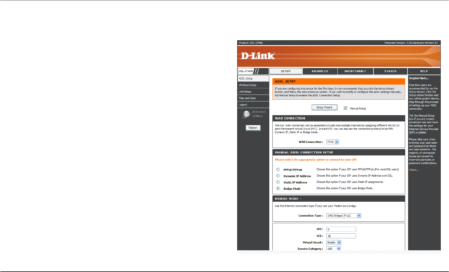
ADSL Setup
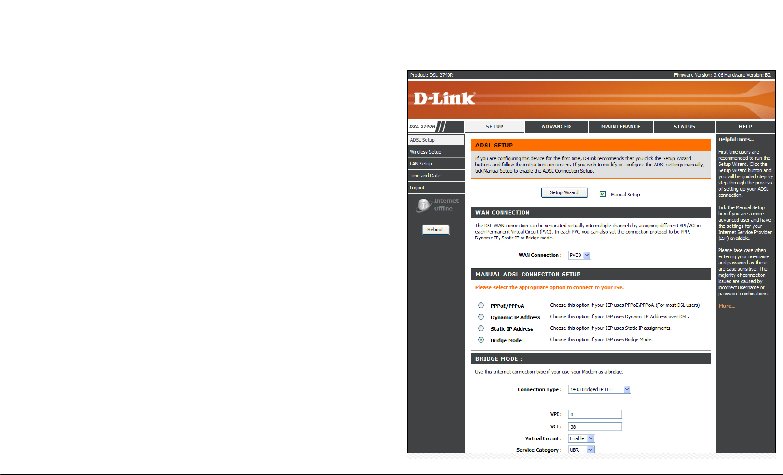
To access the ADSL Setup window, simply login to the Router or click either ADSL Setup in the Setup directory or Setup on the tool bar at the top
of the Web manager window. The Manual Setup check box is selected by default. If not, tick the check box to display the following window:
To configure the Router’s basic configuration settings without running
the Setup Wizard, you can access the windows used to configure ADSL
Setup, LAN Setup, Time and Date, and Parental Control settings directly
from the Setup directory.
To access the ADSL Setup windows for Manual ADSL Connection
Setup for PPPoE/PPPoA, Dynamic IP Address, Static IP Address, and
Bridge Mode, click on the ADSL Setup link button on the left side of the
first window that appears when you successfully access the web
manager.
The Router also allows you to change the Web manager’s language
settings using the drop-down menu on the left side of the window. The
choices are: English, Spanish, French, Italian, and German.
Click the PPPoE/PPPoA radio button to access the first Manual ADSL
Connection Setup window:
Section 3 – Configuration
D-Link DSL-2740R User Manual 22
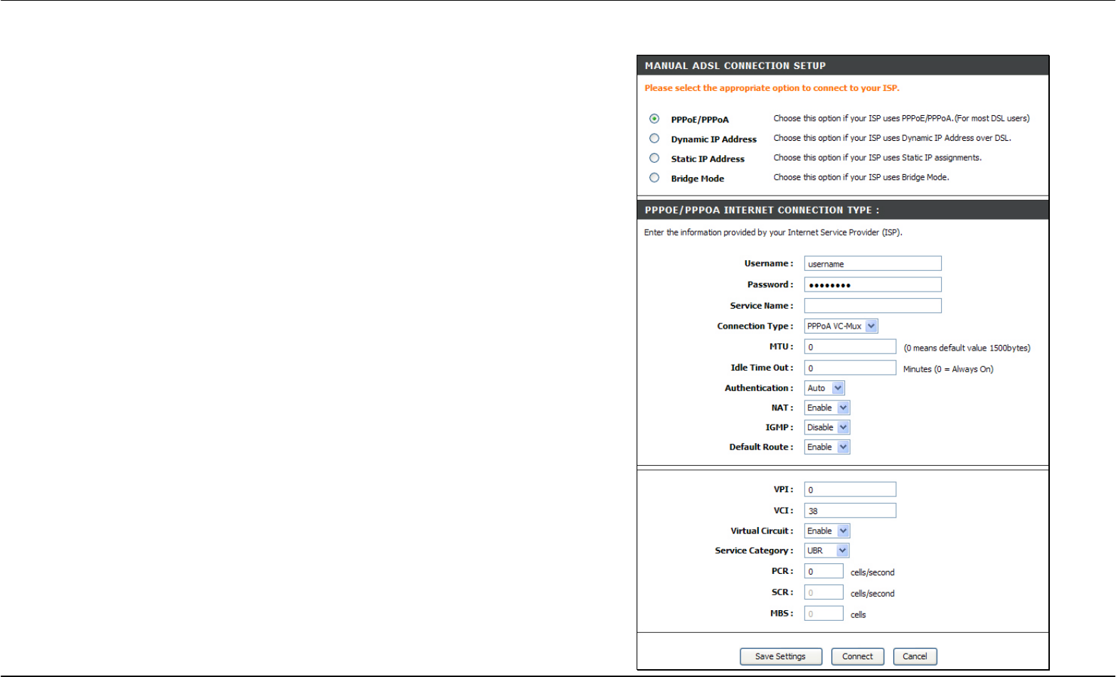
PPPoE/PPPoA
To configure a PPPoE or PPPoA type WAN connection, follow these
steps:
1. Type the Username and Password used for your ADSL account.
A typical User Name will be in the form “user1234@isp.co.uk.”
The Password may be assigned to you by your ISP or you may
have selected it when you set up the account with your ISP. The
Service Name field is used for the name of your Internet Service
Provider. This is optional.
2. Choose the Connection Type from the drop-down menu. This
defines both the connection protocol and encapsulation method
used for your ADSL service. The available options are PPPoE
LLC, PPPoE VC-Mux, PPPoA LLC and PPPoA VC-Mux. If you
have not been provided specific information for the Connection
Type setting, leave the default setting.
3. Leave the MTU value at the default setting unless you have
specific reasons to change this.
4. Some users will want to set an Idle Time Out. This is an age-out
value, in minutes, before the Router times out.
5. If you are instructed to change the VPI or VCI values, type in the
values assigned for your account.
6. When you are satisfied that all the WAN settings are configured
correctly, click the Save Settings button. This will save the
settings and reboot the Router to let your changes take effect.
7. Upon restarting, the Router should automatically establish the
WAN connection. If it does not, click the Connect button at the
bottom of this window.
Section 3 – Configuration
D-Link DSL-2740R User Manual 23
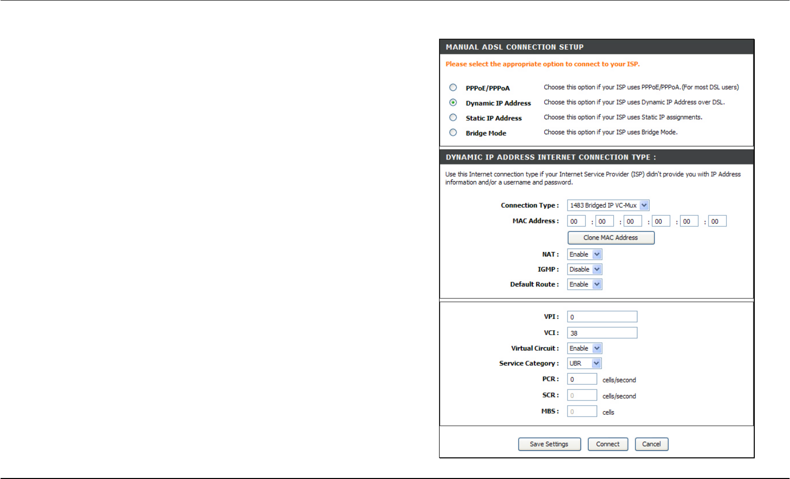
Dynamic IP Address
A
Dynamic IP Address connection configures the Router to automatically
obtain its global IP address from a DHCP server on the ISP’s network.
The service provider assigns a global IP address from a pool of
addresses available to the service provider. Typically the IP address
assigned has a long lease time, so it will likely be the same address
each time the Router requests an IP address.
To configure a Dynamic IP Address WAN connection, follow these steps:
1. Choose the Connection Type from the drop-down menu. This
defines both the connection protocol and encapsulation method
used for your ADSL service. The available options are 1483
Bridged IP LLC and 1483 Bridged IP VC-Mux. If you have not
been provided specific information for the Connection Type
setting, leave the default setting.
2. Some ISPs record the unique MAC Address of your computer’s
Ethernet adapter when you first access their network. This can
prevent the Router (which has a different MAC address) from
being allowed access to the ISPs network (and the Internet). To
clone the MAC address of your computer’s Ethernet adapter, clic
k
the Clone MAC Address button.
3. If you are instructed to change the VPI or VCI values, type in the
values assigned for your account.
4. When you are satisfied that all the WAN settings are configured
correctly, click the Save Settings button. This will save the
settings and reboot the Router to let your changes take effect.
5. Upon restarting, the Router should automatically establish the
WAN connection. If it does not, click the Connect button at the
bottom of this window.
Section 3 – Configuration
D-Link DSL-2740R User Manual 24
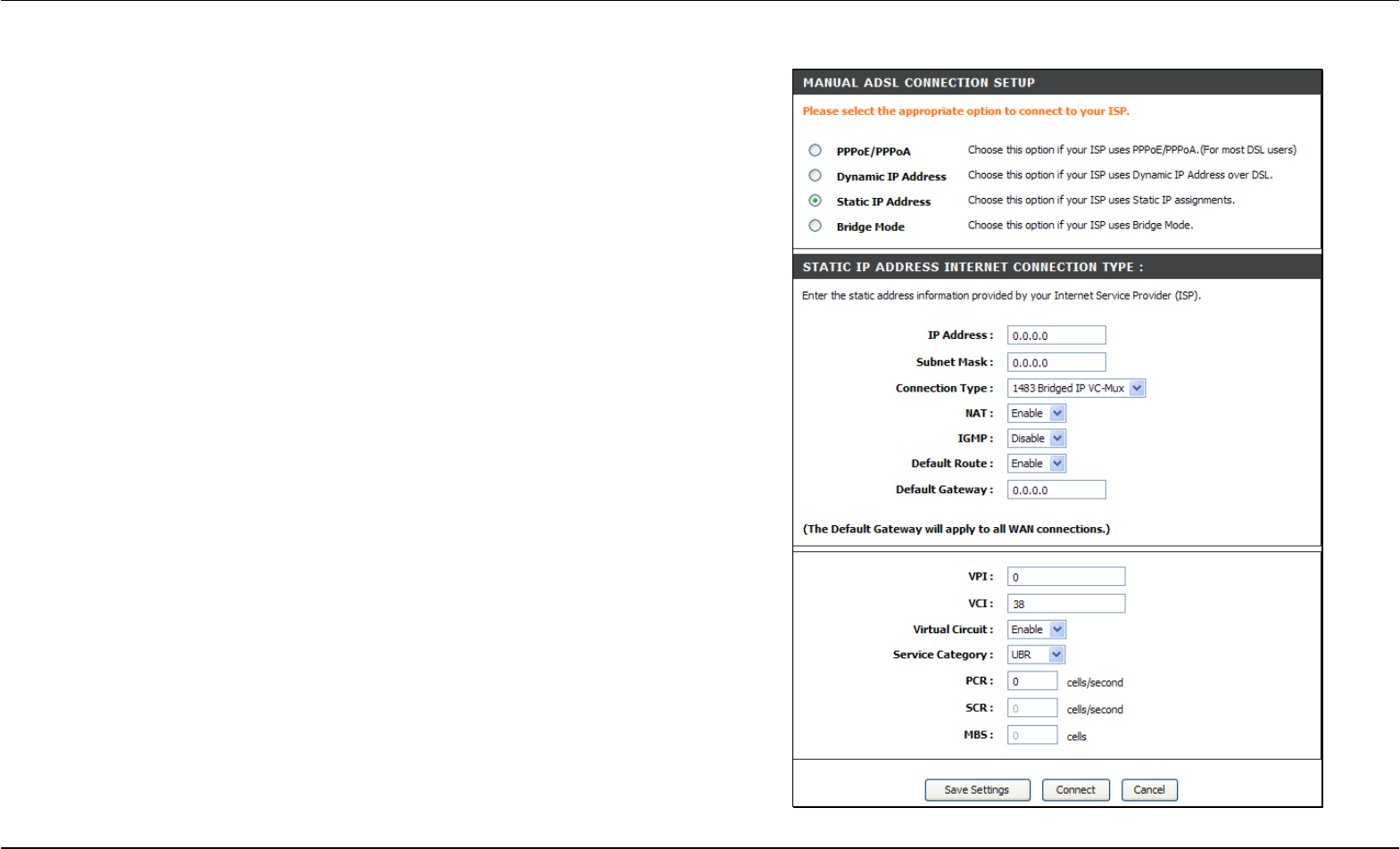
Static IP Address
When the Router is configured to use Static IP Address assignment for
the WAN connection, you must manually assign a global IP Address,
Subnet Mask, and Default Gateway IP address used for the WAN
connection.
To configure a Static IP Address WAN connection, follow these steps:
1. Change the IP Address, Subnet Mask, and Default Gateway as
instructed by your ISP. These are the global IP settings for the
WAN interface. This is the “visible” IP address of your account.
Your ISP should have provided these IP settings to you. If your
ISP also asks you to change DNS server IP addresses, enter the
Preferred DNS Server and Alternate DNS Server information
manually.
2. Choose the Connection Type from the drop-down menu. This
defines both the connection protocol and encapsulation method
used for your ADSL service. The available options are 1483
Bridged IP LLC, 1483 Bridged IP VC-Mux, 1483 Routed IP LLC,
and 1483 Routed IP VC-Mux. If you have not been provided
specific information for this setting, leave the default setting.
3. If you are instructed to change the VPI or VCI values, type in the
values assigned for your account.
4. When you are satisfied that all the WAN settings are configured
correctly, click the Save Settings button. This will save the
settings and reboot the Router to let your changes take effect.
5. Upon restarting, the Router should automatically establish the
WAN connection. If it does not, click the Connect button at the
bottom of this window.
Section 3 – Configuration
D-Link DSL-2740R User Manual 25
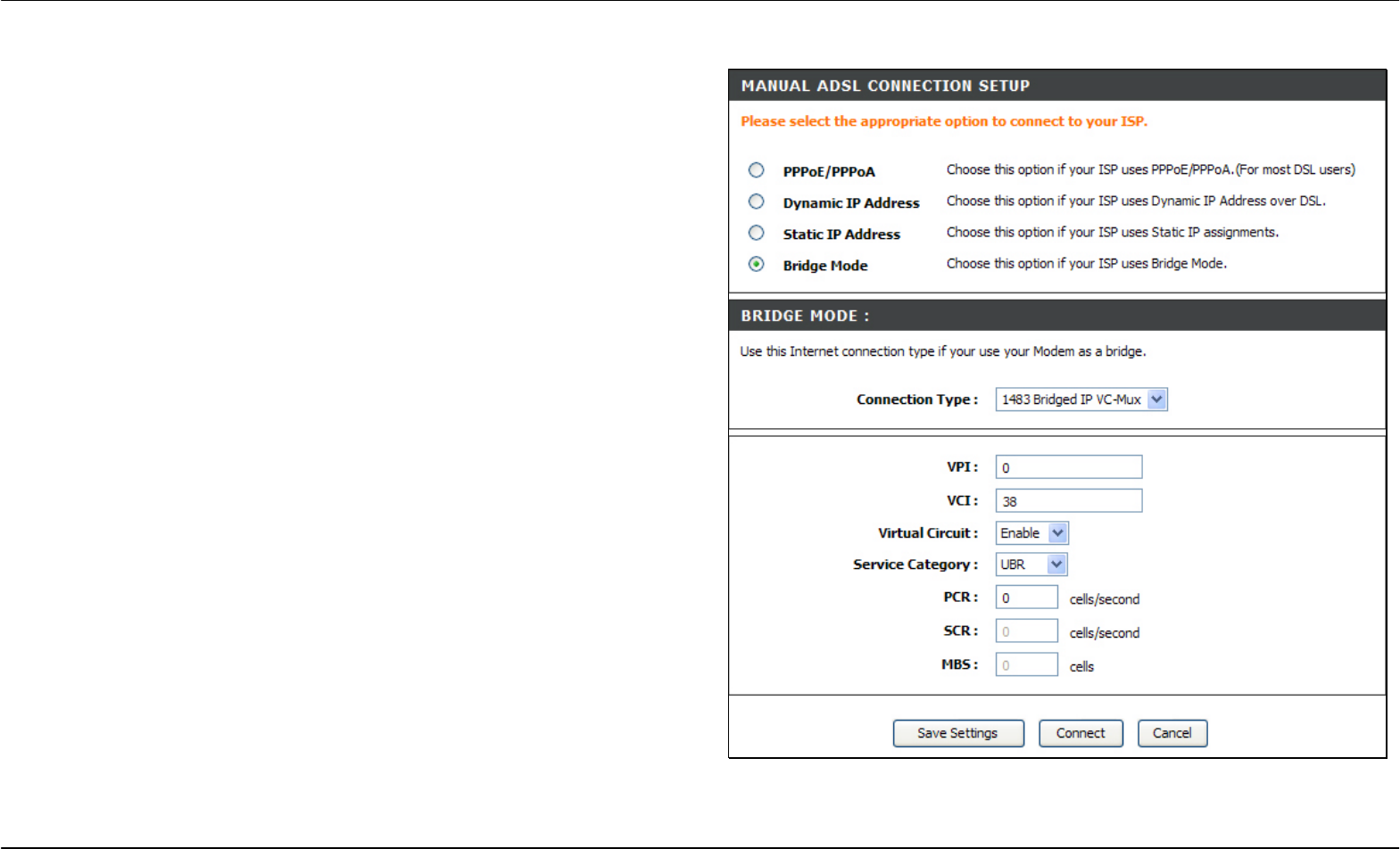
Bridge Mode
For Bridged connections it will be necessary for most users to install
additional software on any computer that will use the Router for Internet
access. The additional software is used for the purpose of identifying
and verifying your account, and then granting Internet access to the
computer requesting the connection. The connection software requires
the user to enter the User Name and Password for the ISP account. This
information is stored on the computer, not in the Router.
.
To configure a Static IP Address WAN connection, follow these steps:
1. Choose the Connection Type from the drop-down menu. This
defines both the connection protocol and encapsulation method
used for your ADSL service. The available options are 1483
Bridged IP LLC and 1483 Bridged IP VC-Mux. If you have not
been provided specific information for this setting, leave the
default setting.
2. If you are instructed to change the VPI or VCI values, type in the
values assigned for your account.
3. When you are satisfied that all the WAN settings are configured
correctly, click the Save Settings button. This will save the
settings and reboot the Router to let your changes take effect.
4. Upon restarting, the Router should automatically establish the
WAN connection. If it does not, click the Connect button at the
bottom of this window.
Section 3 – Configuration
D-Link DSL-2740R User Manual 26
Wireless Setup
To access the Wireless Setup window, click the Wireless Setup button in the Setup directory.
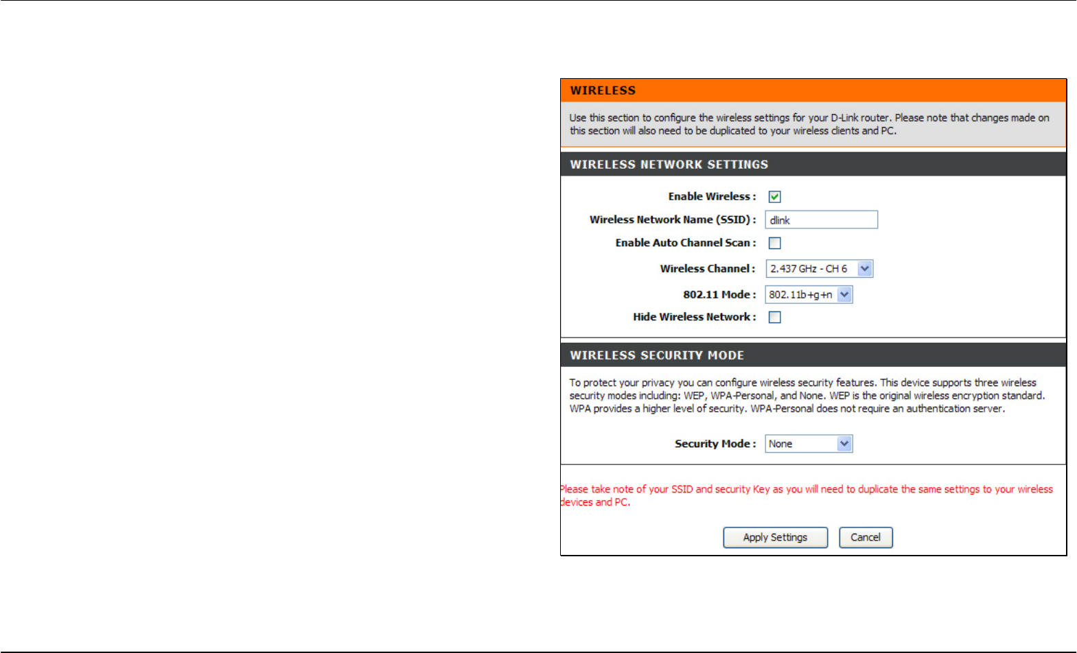
The two essential settings for wireless LAN operation are the Wireless
Network Name (SSID) and Wireless Channel. The SSID (Service Set
Identifier) is used to identify a group of wireless LAN components. The
SSID can be visible (broadcast) or hidden (not broadcast).
Follow the instructions below to change wireless network settings.
1. The Wireless LAN is enabled by default. To disable the wireless
interface, click to deselect the Enable Wireless check box. If the
wireless interface has been disabled, click the Enable Wireless
check box again to select it.
2. The Wireless Network Name (SSID) can be changed to suit
your wireless network. Remember that any wireless device using
the access point must have the same SSID and use the same
channel.
3. If you want the Router to scan the available channel
automatically, tick the Enable Auto Channel Scan check box.
4. Select a wireless protocol in the 802.11 Mode drop-down list.
5. The Hide Wireless Network is not selected by default. To make
the wireless network invisible, tick the Hide Wireless Network
check box.
To configure Wireless Security, select WEP or WPA-Personal in the
Security Mode drop-down list.
Section 3 – Configuration
D-Link DSL-2740R User Manual 27
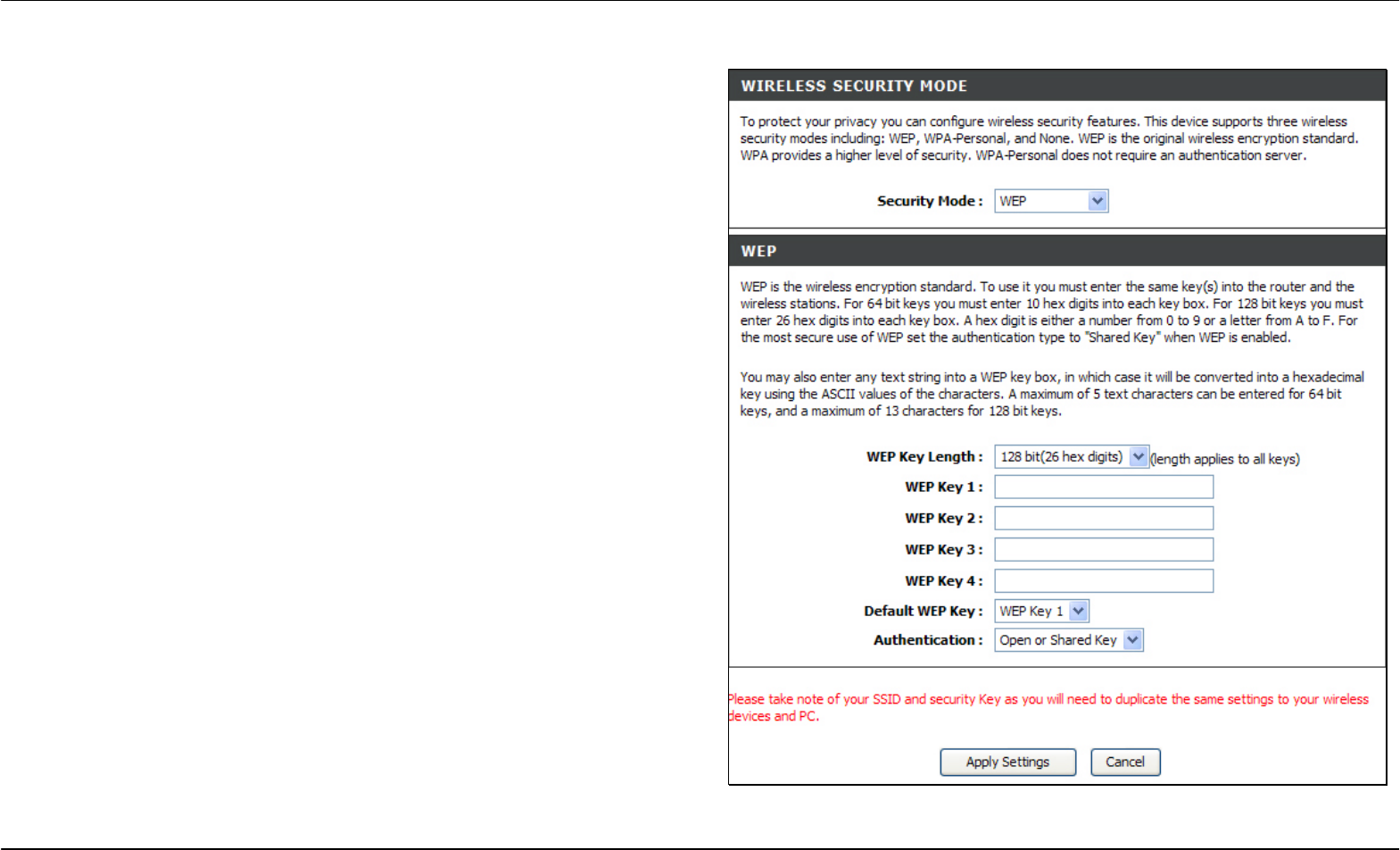
WEP
WEP (Wireless Encryption Protocol or Wired Equivalent Privacy)
encryption can be enabled for security and privacy. WEP encrypts the
data portion of each frame transmitted from the wireless adapter using
one of the predefined keys. Decryption of the data contained in each
packet can only be done if the both the receiver and transmitter have the
correct key.
By default, authentication is disabled on the access point. To enable
WEP, select WEP in the Security Mode drop-down list.
Select the WEP Key Length from the drop-down menu. The available
key lengths are 128 bit(26 hex digits) or 64 bit(10 hex digits)
encryption. In the spaces provided, type in WEP Key 1, WEP Key 2,
WEP Key 3 and WEP Key 4. The length of the character string used of
the keys depends on the level (Key Length) of encryption selected.
Only one key can be active. The active key is selected in the Default
WEP Key drop-down list.
Click the Apply Settings button to save the settings.
Section 3 – Configuration
D-Link DSL-2740R User Manual 28
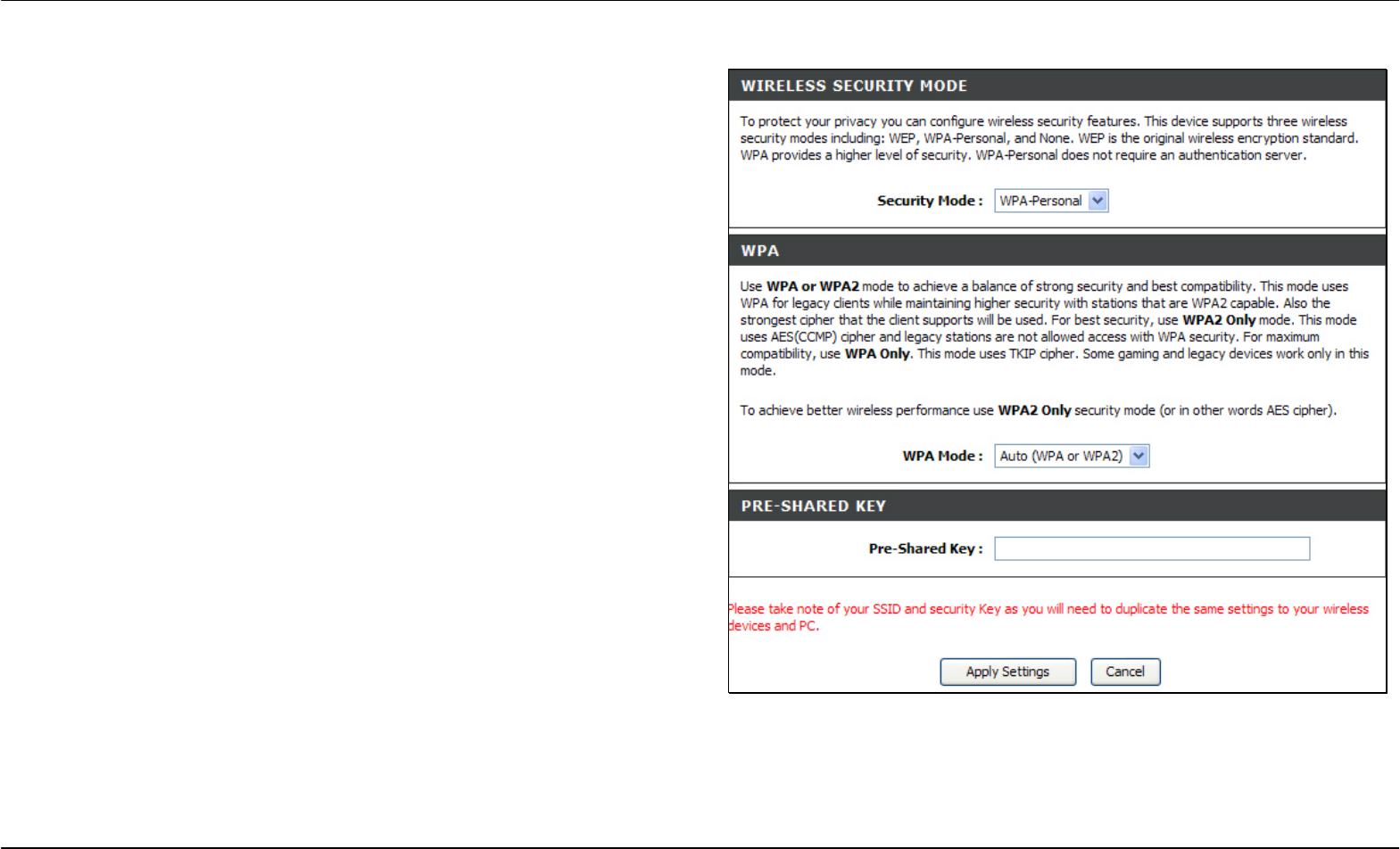
WPA-Personal
WPA uses an encryption method combined with an authentication
procedure that requires an acceptance of a pre-configured password.
WPA or Wireless Protection Access is an improved standard of wireless
security. The T-KD 318 also supports two common encryption types
TKIP and AES (explained below).
To configure WPA settings, select WPA-Personal in the Security Mode
drop-down list.
Select WPA to use TKIP encryption or select WPA2 to use AES
encryption in the WPA Mode drop-down list. The encryption algorithm
TKIP (Temporal Key Integrity Protocol) uses per packet key generation
(based on WEP), while AES (Advanced Encryption Standard) is a block-
based encryption method. Both methods require entry of a pre-shared
key to allow association. Type a password from 8 to 64 characters long
in the Pre-Shared Key field.
Click the Apply Settings button to save the settings.
Section 3 – Configuration
D-Link DSL-2740R User Manual 29
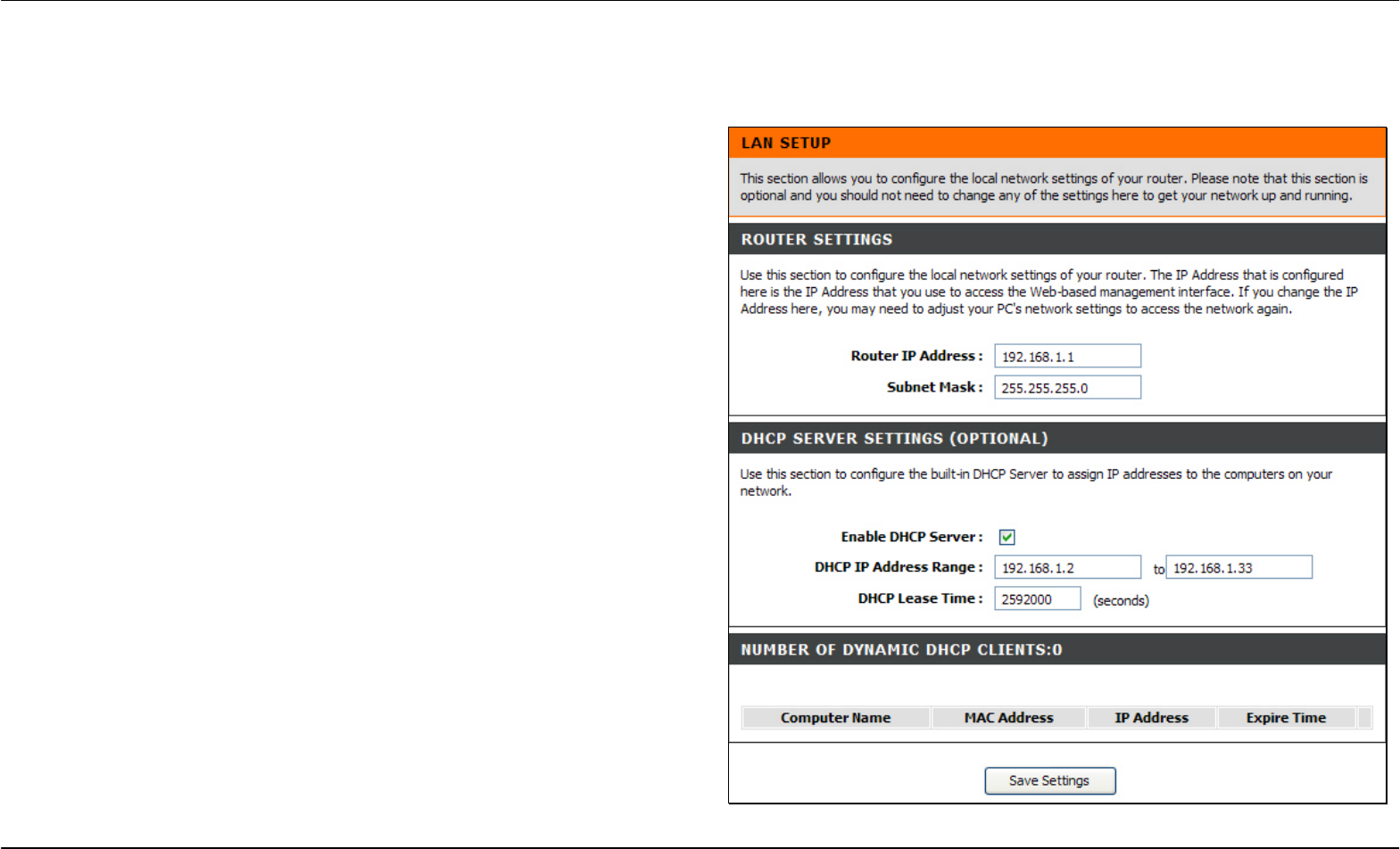
LAN Setup
To access the LAN Setup window, click the LAN Setup button in the Setup directory.
You can configure the LAN IP address to suit your preference. Many
users will find it convenient to use the default settings together with
DHCP service to manage the IP settings for their private network. The IP
address of the Router is the base address used for DHCP. In order to
use the Router for DHCP on your LAN, the IP address pool used for
DHCP must be compatible with the IP address of the Router. The IP
addresses available in the DHCP IP address pool will change
automatically if you change the IP address of the Router. See the next
section for information on DHCP setup.
To change the LAN Router IP Address or Subnet Mask, type in the
desired values in the Router Settings section and click the Save
Settings button. Your web browser should automatically be redirected to
the new IP address. You will be asked to login again to the Router’s web
manager.
The DHCP server is enabled by default for the Router’s Ethernet LAN
interface. DHCP service will supply IP settings to workstations
configured to automatically obtain IP settings that are connected to the
Router though the Ethernet port. When the Router is used for DHCP it
becomes the default gateway for DHCP client connected to it. Keep in
mind that if you change the IP address of the Router the range of IP
addresses in the pool used for DHCP on the LAN will also be changed.
The IP address pool can be up to 253 IP addresses.
There are two options for DHCP service:
• You can use the Router as a DHCP server for your LAN.
• You can disable DHCP service and manually configure IP settings
for workstations.

Section 3 – Configuration
D-Link DSL-2740R User Manual 30
You may also configure DNS settings when using the Router in DHCP mode (Advanced > DNS Setup). When “Obtain DNS server address
automatically“ is clicked under DNS Server Configuration on the DNS Setup window, the Router will automatically relay DNS settings to properly
configured DHCP clients. To manually enter DNS IP addresses, click the “Use the following DNS server addresses“ radio button and type in a
Preferred DNS Server and Alternate DNS Server in the fields provided. The manually configured DNS settings will be supplied to clients that are
configured to request them from the Router.
Follow the instructions below according to which of the above DHCP options you want to use. When you have configured DHCP as you want, click
the Apply Settings button to commit the new settings.
Use the Router for DHCP
To use the built-in DHCP server, tick the Enable DHCP Server check box in the DHCP Server Settings (Optional) section if it is not already selected.
The IP address pool settings can be adjusted. The DHCP IP Address Range starts with the lowest available IP address (default = 192.168.1.2). If
you change the IP address of the Router this will change automatically to be 1 more that the IP address of the Router. The DHCP IP Address Range
ends with the highest IP address number in the pool. Type in the DHCP Lease Time in the entry field provided. This is the amount of time in hours
that a workstation is allowed to reserve an IP address in the pool if the workstation is disconnected from the network or powered off.
Disable the DHCP Server
To disable DHCP, deselect the Enable DHCP Server check box in the DHCP Server Settings (Optional) section and click the Save Settings button.
Choosing this option will gray out most of the setting options on this window and require that workstations on the local network be configured
manually or use another DHCP server to obtain IP settings.
If you configure IP settings manually, make sure to use IP addresses in the subnet of the Router. You will need to use the Router’s IP address as the
Default Gateway for the workstation in order to provide Internet access.
Section 3 – Configuration
D-Link DSL-2740R User Manual 31
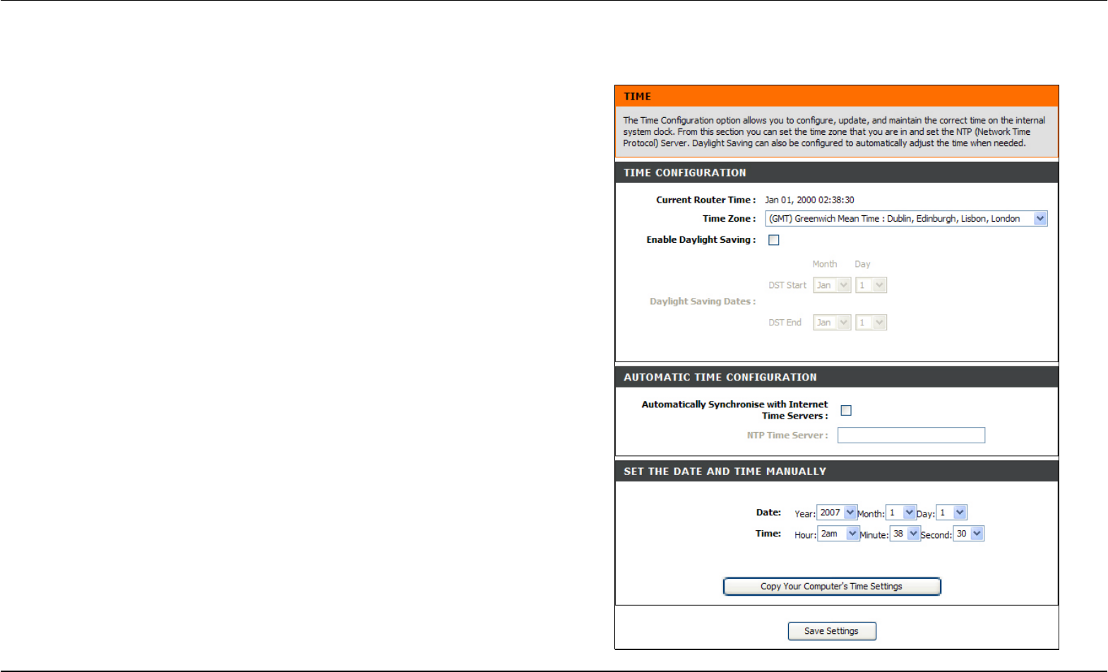
Time and Date
To access the Time and Date window, click the Time and Date button in the Setup directory.
The Router provides a number of options to maintain current date and
time including NTP.
To configure system time on the Router, select the method used to
maintain time. The options available include Network Time Protocol
(default), using your computer’s system clock (deselect the
A
utomatically synchronize with Internet time servers check box and then
click the Copy Your Computer’s Time Settings button), or set the time
and date manually (deselect the Automatically synchronize with Internet
time servers check box and make the desired changes).
If you opt to use NTP, you must use the drop-down menu to select the
NTP server URL in the First NTP Time Server field. You may also want
to choose a Second NTP Time Server using the drop-down menu.
The Router also allows you to set the time zone you are in by using the
Time Zone drop-down menu. In addition, you can configure Daylight
Saving by ticking the Enable Daylight Saving check box and then using
the drop-down menus to configure the desired Daylight Saving Offset
and Daylight Saving starting and ending dates.
When you are finished, click the Save Settings button to set the system
time and date information.