D Link SL2750UT1 Wireless N ADSL2+ 3G USB Router User Manual Manual statement
D Link Corporation Wireless N ADSL2+ 3G USB Router Manual statement
D Link >
User Manual

DSL-2750U/DSL-2750B User manual
DSL-2750U/ DSL-2750B/
DSL-2751U/ DSL-2751B
User Manual

DSL-2750U/DSL-2750B User manual
Contents
1 Introduction ........................................................................................................ 1
1.1 Packing List ................................................................................................. 1
1.2 Safety Precautions................................................................................ 1
1.3 LEDs and Interfaces..............................................................................2
1.4 System Requirements ........................................................................... 4
1.5 Features ................................................................................................ 5
2 Hardware Installation ......................................................................................... 7
3 About the Web Configurator............................................................................... 8
3.1 Access the Device.................................................................................9
3.2 Setup ................................................................................................... 10
3.2.1 Wizard....................................................................................... 10
3.2.2 Internet Setup ........................................................................... 16
3.2.3 Wireless Connection................................................................. 25
3.2.4 Local Network...........................................................................29
3.2.5 Time and Date.......................................................................... 32
3.2.6 3G Internet Setup............................................................................... 34
3.2.7 Logout.......................................................................................35
3.3 Advanced............................................................................................. 35
3.3.1 Wireless Settings......................................................................35
3.3.2 Port Forwarding ........................................................................ 48
3.3.3 Port Triggering .......................................................................... 51
3.3.4 DMZ..........................................................................................54
3.3.5 Parental Control........................................................................54
3.3.6 Filtering Options........................................................................ 59
3.3.7 DNS .......................................................................................... 65
3.3.8 Dynamic DNS ........................................................................... 66
3.3.9 Storage Service ........................................................................ 68
3.3.10 Multicast .............................................................................. 70
3.3.11 Network Tools......................................................................71
3.3.12 Routing................................................................................84
3.3.13 RIP ...................................................................................... 87
3.3.14 MultiNat ............................................................................... 88
3.3.15 Schedules............................................................................ 89
3.3.16Logout ................................................................................. 90 i
3.4 Maintenance........................................................................................90
3.4.1 System......................................................................................90
3.4.2 Firmware Update ...................................................................... 92
3.4.3 Access Controls........................................................................ 92
3.4.4 Diagnostics ............................................................................... 96
3.4.5 System Log............................................................................... 97
3.4.6 Logout.......................................................................................99
3.5 Status................................................................................................... 99
3.5.1 Device Info................................................................................ 99
3.5.2 Wireless Clients......................................................................101
3.5.3 DHCP Clients.......................................................................... 101
3.5.4 Logs........................................................................................102
3.5.5 Statistics.................................................................................. 102
3.5.6 Route info ............................................................................... 104
3.5.7 Logout.....................................................................................104

DSL-2750U/DSL-2750B User manual
1 Introduction
The DSL-2750U/ DSL-2750B/ DSL-2751U/ DSL-2751B is a highly integrated ADSL2/2+
Integrated Access Device, which is an advanced gateways incorporating Ethernet Switch
and Wireless home networking Access Point ,complied with the IEEE802.11b/g /n stan-
dards. It is usually prefered to provide high access performance applications for the indi-
vidual users,the SOHO,the small enterprise and so on.
1.1 Packing List
1 x DSL-2750U/ DSL-2750B/ DSL-2751U/ DSL-2751B
1 x external splitter
1 x power adapter
2 x telephone cables (RJ-11)
1x Ethernet cable (RJ-45)
1 x USB cable (usb)
1 x user manual
1 x quality guarantee card
1 x certificate of quality
1.2 Safety Precautions
Follow the following instructions to prevent the device from risks and damage caused by
fire or electric power:
Use volume labels to mark the type of power.
Use the power adapter packed within the device package.
Pay attention to the power load of the outlet or prolonged lines. An overburden
power outlet or damaged lines and plugs may cause electric shock or fire accident.
Check the power cords regularly. If you find any damage, replace it at once.
Proper space left for heat dissipation is necessary to avoid damage caused by
overheating to the device. The long and thin holes on the device are
DSL-2750U/DSL-2750B User manual
designed for heat dissipation to ensure that the device works normally. Do not
cover these heat dissipation holes.
Do not put this device close to a place where a heat source exists or high temper-
ature occurs. Avoid the device from direct sunshine.
Do not put this device close to a place where it is over damp or watery. Do not spill
any fluid on this device.
Do not connect this device to any PCs or electronic products, unless our customer
engineer or your broadband provider instructs you to do this, because any wrong
connection may cause power or fire risk.
Do not place this device on an unstable surface or support.
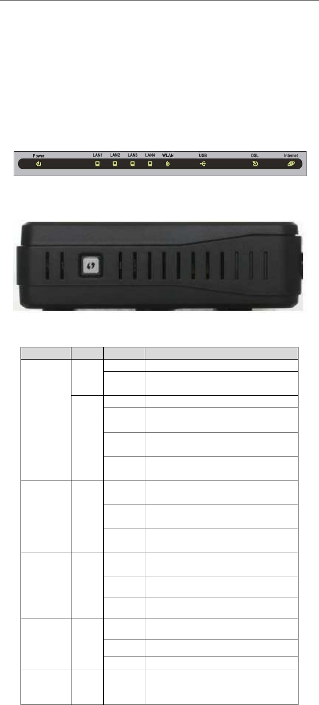
1.3 LEDs and Interfaces
Front Panel
Figure 1 Front panel
Side Panel
The following table describes the LEDs of the device.
LED Color
Status Description
Power
Green
Off The power is off.
On The power is on and the initialization is
normal.
Red On The device is initiating.
Blinks The firmware is upgrading.
LAN
1/2/3/4 Green
Off No LAN link.
Blinks Data is being transmitted through the
LAN interface.
On The connection of LAN interface is nor-
mal.
WLAN Green
Blinks Data is being transmitted through the
WLAN interface.
On The connection of WLAN interface is
normal.
Off The WLAN connection is not estab-
lished.
USB Green
On The connection of 3G or USB flash disk
has been established.
Blink Data is being transmitted.
Off No signal is detected.
DSL Green
Off Initial self-test failed.
Blinks The device is detecting itself.
On Initial self-test of the unit has passed.
Internet Green
Off
The device is under the Bridge mode,
DSL connection is not present, or the
power is off.

DSL-2750U/DSL-2750B User manual
LED Color
Status Description
On IP is connected and no traffic is de-
tected.
Red On The device attempted an IP connection,
but failed.
WPS (on
the side
panel)
Green
Blinks WPS negotiation is enabled, waiting for
clients.
Off Device is ready for new WPS to setup.
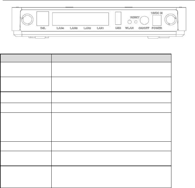
Rear Panel
DSL-2750U/DSL-2750B User manual
Figure 2 Rear panel
The following table describes the interface of the device.
Interface/Button Description
DSL RJ-11 interface that connects to the telephone set
through the telephone cable.
LAN4/3/2/1 Ethernet RJ-45 interfaces that connect to the Ethernet
interfaces of computers or Ethernet devices.
USB USB port, for connecting the 3G network card or other
USB storage devices.
WLAN Button to enable or disable WLAN.
Reset
Reset to the factory defaults. To restore factory de-
faults, keep the device powered on and push a paper
clip into the hole. Press down the button for over 5
seconds and release.
ON/OFF Power on or off.
Power Interface that connects to the power adapter. The
power adapter output is: 12 V DC 1A.
WPS (on the side
panel) WPS button to setup connection to Client
1.4 System Requirements
Recommended system requirements are as follows:
An 10 baseT/100BaseT Ethernet card is installed on your PC
A hub or switch (attached to several PCs through one of Ethernet interfaces on the
device)
Operating system: Windows 98SE, Windows 2000, Windows ME, Windows XP,
Windows Vista or Windows 7

DSL-2750U/DSL-2750B User manual
Internet Explorer V5.0 or higher, Netscape V4.0 or higher, or Firefox 1.5 or higher
4
1.5 Features
The device supports the following features:
Various line modes
External PPPoE dial-up access
Internal PPPoE and PPPoA dial-up access
Leased line mode
1483B, 1483R, and MER access
Multiple PVCs (eight at most) and these PVCs can be isolated from each other
A single PVC with multiple sessions
Multiple PVCs with multiple sessions
Binding of ports with PVCs
802.1Q and 802.1P protocol
DHCP server
NAT and NAPT
Static route
Firmware upgrade: Web, TFTP, FTP
Reset to the factory defaults
DNS relay
Virtual server
DMZ
Two-level passwords and user names
Web user interface
Telnet CLI
System status display
PPP session PAP and CHAP
IP filter
IP QoS
Remote access control
Line connection status test
Remote management (telnet and HTTP, TR069))
Backup and restoration of configuration file
Ethernet interface supports crossover detection, auto-correction and polarity correc-
tion
UPnP
USB storage
Printer server
DSL-2750U/DSL-2750B User manual
2 Hardware Installation
Step 1 Connect the DSL port of the device and the Modem port of the splitter
with a telephone cable. Connect the phone to the Phone port of the
splitter through a telephone cable. Connect the incoming line to the Line
port of the splitter. The splitter has three ports:
Line: Connect to a wall phone port (RJ-11 jack).
Modem: Connect to the DSL port of the device.
Phone: Connectto a telephone set.
Step 2 Connect the LAN port of the device to the network card of the PC
through an Ethernet cable (MDI/MDIX).
Note:
Use twisted-pair cables to connect with the Hub or switch.
Step 3 Plug one end of the power adapter to the wall outlet and connect the
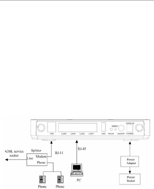
other end to the Power port of the device. Connection 1: Figure 3 displays the
application diagram for the connection of the device, PC, splitter and telephone sets, when
no telephone set is placed before the splitter.
DSL-2750U/DSL-2750B User manual
Figure 3 Connection diagram (without telephone sets before the splitter)
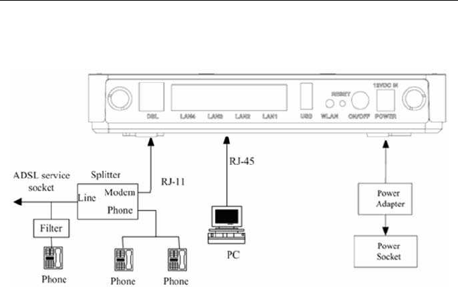
Connection 2: Figure 4 displays the application diagram for the connection of the device,
PC, splitter and telephone sets when a telephone set is placed before the splitter.As illu-
strated in the following figure, the splitter is installed close to the device.
Figure 4 Connection diagram (with a telephone set before the splitter)
Connection 1 is recom-
mended.
Note:
When connection 2 is used, the filter must be installed close to the telephone
cable. See Figure 4. Do not use the splitter to replace the filter.
Installing a telephone directly before the splitter may lead to failure of connection be-
tween the device and the central office, or failure of Internet access, or slow connection
speed. If you really need to add a telephone set before the splitter, you must add a mi-
crofilter before a telephone set. Do not connect several telephones before the splitter or
connect several telephones with the microfilter.
3 About the Web Configurator
DSL-2750U/DSL-2750B User manual
This chapter describes how to configure the device by using the Web-based configuration
utility.
3.1 Access the Device
The following is the detailed description of accesing the device for the first time.
Step 4 Open the Internet Explorer (IE) browser and enter http://192.168.1.1.
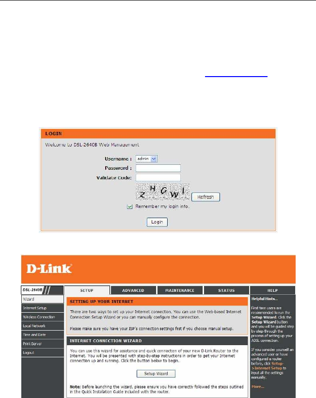
Step 5 The Login page shown in the following figure appears. Enter the user
name and password.
The user name and password of the super user are admin and admin.
The user name and password of the normal user are user and user.
If you log in as the super user successfully, the page shown in the following figure appears.
If the login information is incorrect, click Try Again in the page that pops up to log in
again.
DSL-2750U/DSL-2750B User manual
3.2 Setup
3.2.1 Wizard
Wizard enables fast and accurate configuration of Internet connection and other impor-
tant parameters. The following sections describe these various configuration parameters.
When subscribing to a broadband service, you should be aware of the method, by which
you are connected to the Internet. Your physical WAN device can be Ethernet, DSL, or
both. Technical information about the properties of your Internet connection is provided
by your Internet service provider (ISP). For example, your ISP should inform you whether
you are connected to the Internet using a static or dynamic IP address, or the protocol,
such as PPPoA or PPPoE, that you use to communicate over the Internet. Step 1
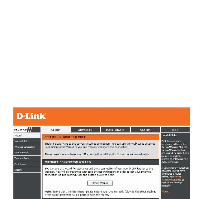
Choose Setup > Wizard. The page shown in the following figure
appears.
DSL-2750U/DSL-2750B User manual
Step 2 Click Setup Wizard. The page shown in the following figure appears.
10
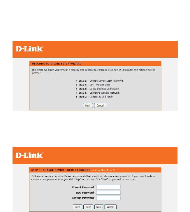
Step 3 There are four steps to configure the device. Click Next to continue.Step 4 Change
Device Login Password.The default password is "admin", in order to secure your network,
please modify the password. Note: Confirm Password must be the same as "New Pass-
word". Of course, you can click Skip to ignore the step
.
DSL-2750U/DSL-2750B User manual
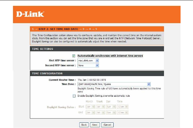
Step 5 Set the time and date.
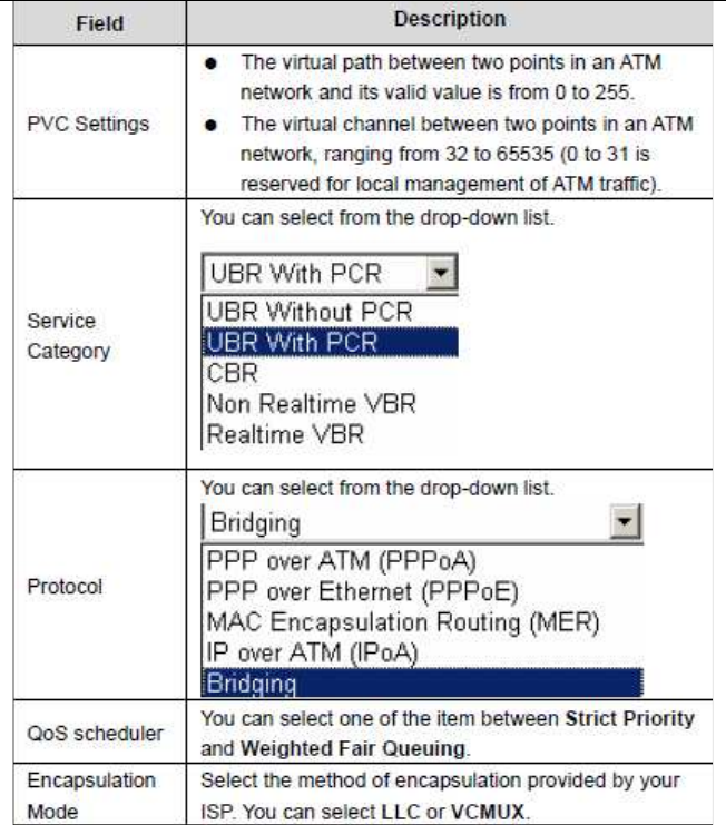
Step 6Configure the Internet connection. Select the country and ISP. Set the VPI and VCI.
If you fail to find the country and ISP from the drop-down lists, select Others.
Click Next. If the Protocol is PPPoE or PPPoA, the page shown in either of the
two following figures appears.
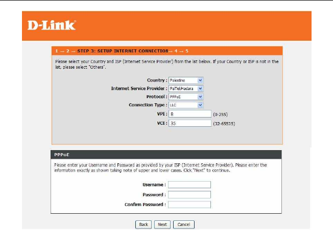
DSL-2750U/DSL-2750B User manual
In this page, enter the user name and password. If the Protocol is Dynamic IP, the page
shown in the following figure appears.
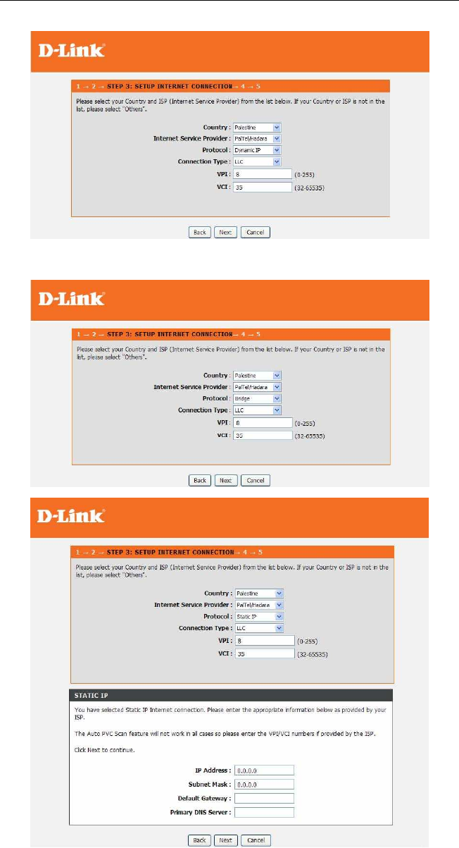
DSL-2750U/DSL-2750B User manual
If the Protocol is Bridge, the page shown in the following figure appears. If the Protocol is
Static IP, the page shown in the following figure appears.
Enter the IP Address, Subnet Mask, Default Gateway, and Primary DNS Server. Click
Next. The page shown in the following page appears.
DSL-2750U/DSL-2750B User manual
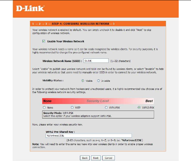
Step 7Configure the wireless network. Enter the information and click Next.
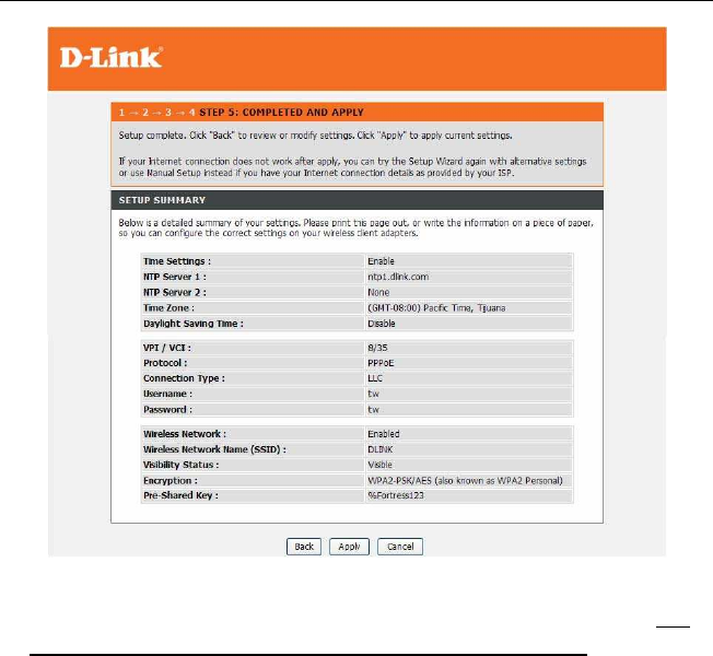
Step 8Completed And Apply. Click Apply to apply current settings and finished the
setup of the DSL-2750U/ DSL-2750B/ DSL-2751U/ DSL-2751B router.Click
Back to review or modify settings.
DSL-2750U/DSL-2750B User manual
Note:
In each step of the Wizard page, you can click Back to review ormo-
dify the previous settings. Click Cancel to exit the wizard page.
3.2.2 Internet Setup
Choose Setup > Internet Setup. The page shown in the following figure appears. In this
page, you can configure the WAN interface of the device.
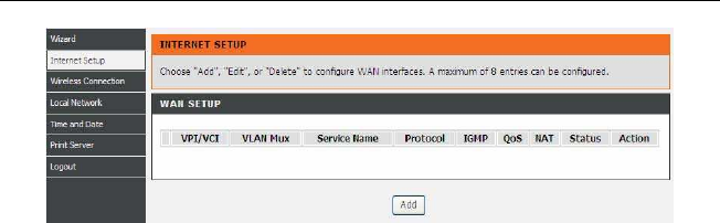
DSL-2750U/DSL-2750B User manual
Click Add in “INTERNET SETUP”. The page shown in the following figure appears.
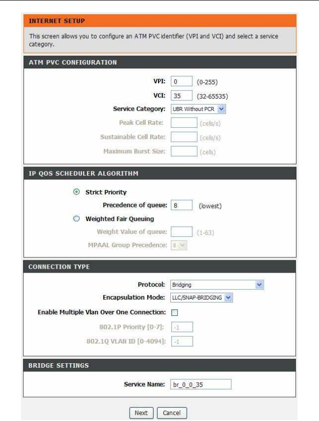
DSL-2750U/DSL-2750B User manual
DSL-2750U/DSL-2750B User manual
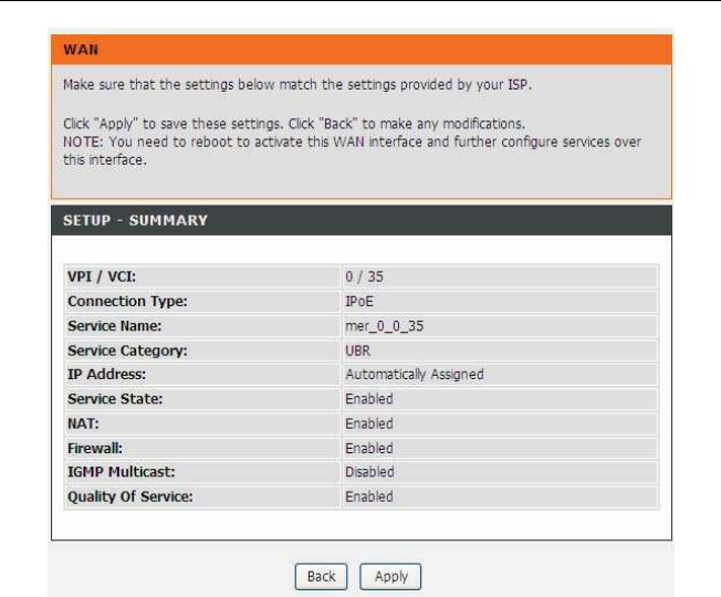
Click Next, the page shown in the following figure appears.
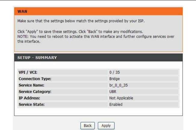
DSL-2750U/DSL-2750B User manual
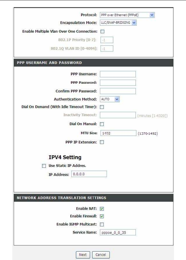
If you select the PPP over Ethernet (PPPoE) as the connection protocol, the follow-
ing page appears.
DSL-2750U/DSL-2750B User manual

DSL-2750U/DSL-2750B User manual
PPP Username: The correct user name that your ISP provides to you.
PPP Password: The correct password that your ISP provides to you.
Authentication Method: The value can be AUTO, PAP, CHAP, or MSCHAP.
Usually, you can select AUTO.
Dial on demand (with idle timeout timer): If this function is enabled, you need
to enter the idle timeout time. Within the preset minutes, if the modem does not
detect the flow of the user continuously, the modem automatically stops the
PPPoE connection. Once it detects the flow (like access to a webpage), the
modem restarts the PPPoE dialup. If this function is disabled, the modem per-
forms PPPoE dial-up all the time. The PPPoE connnection does not stop, unless
the modem is powered off and DSLAM or uplink equipment is abnormal.
MTU Size: Maximum Transmission Unit. Sometimes, you must modify this func-
tion to access network successfully.
PPP IP extension: If this function is enabled, the WAN IP address obtained by
the modem through built-in dial-up can be directly assigned to the PC being at-
tached to the modem (at this time, the modem connects to only one PC). From
the aspect of the PC user, the PC dials up to obtain an IP addres. But actually,
the dial-up is done by the modem. If this function is disabled, the modem itself
obtains the WAN IP address.
Use Static IP Address: If this function is disabled, the modem obtains an IP ad-
dress assigned by an uplink equipment such as BAS, through PPPoE dial-up. If
this function is enabled, the modem uses this IP address as the WAN IP address.
Enable NAT: Select it to enable the NAT functions of the modem. If you do not
want to enable NAT and wish the modem user to access the Internet normally,
you must add a route on the uplink equipment. Otherwise, the access to the In-
ternet fails. Normally, NAT should be enabled.
Enable Firewall: Enable or disable IP filtering.
Enable IGMP Multicast: IGMP proxy. For example, if you wish that the PPPoE
mode supports IPTV, enable this function.
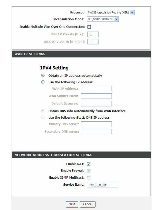
If you select the MAC Encapsulation Routing(MER) as the connection protocol, the fol-
lowing page appears.
DSL-2750U/DSL-2750B User manual

DSL-2750U/DSL-2750B User manual
Obtain an IP address automatically: The modem obtains a WAN IP address au-
tomatically and at this time it enables DHCP client functions. The WAN IP address
is obtained from the uplink equipment like BAS and the uplink equipment is required
to enable the DHCP server functions.
Use the following IP address: If you want to manually enter the WAN IP address,
select this check box and enter the information in the field.
WAN IP Address: Enter the IP address of the WAN interface provided by your ISP.
WAN Subnet Mask: Enter the subnet mask concerned to the IP address of the
WAN interface provided by your ISP.
Default Gateway: Enter the default gateway.
Obtain DNS info automatically from WAN interface: You can get DNS server
information from the selected WAN interface
Use the following Static DNS IP address: If you want to manually enter the IP
address of the DNS server, select this check box and enter the information in the
fields.
Primary DNS server: Enter the IP address of the primary DNS server.
Secondary DNS server: Enter the IP address of the secondary DNS server pro-
vided by your ISP.
After proper settings, click Next.
DSL-2750U/DSL-2750B User manual
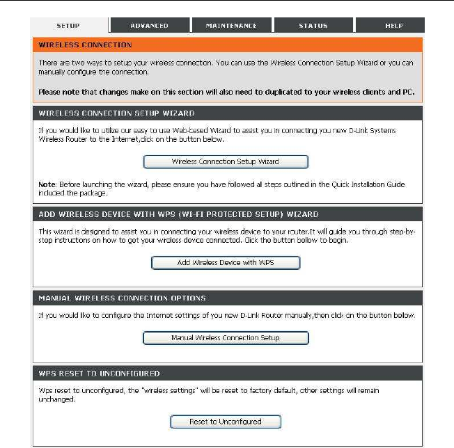
3.2.3 Wireless Connection
This section includes the wireless connection setup wizard and WPS setup wizard. There
are two ways to setup your wireless connection. You can use the Wireless Connection
Setup Wizard or you can manually configure the connection. Choose Setup > Wireless
Connection. The Wireless Connection page shown in the following figure appears.
DSL-2750U/DSL-2750B User manual
3.2.3.1 Wireless Wizard
In Wireless Connection page, Click “Wireless Connection Setup Wizard”, the page
shown in the following figure appears.
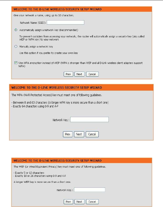
DSL-2750U/DSL-2750B User manual
If you only select “Manually assign a network key”, click “Next”, the page shown in the
following figure appears.
After you enter the network key, the page shown in the following figure appears, you can
confirm the wireless settings in this page.
DSL-2750U/DSL-2750B User manual
Click Save to save the settings.
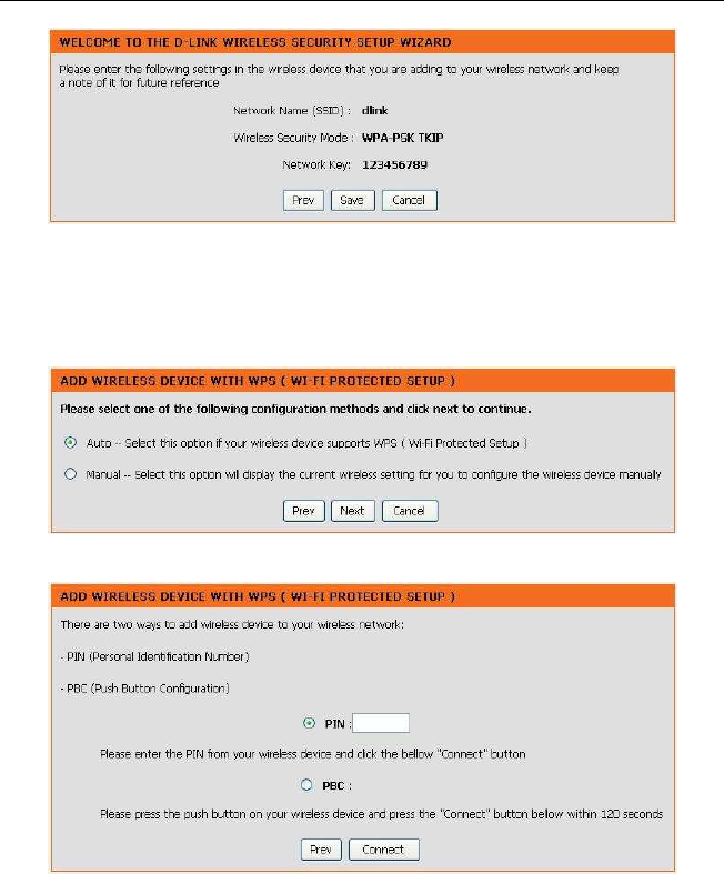
3.2.3.2 Wireless Device Add
In Wireless Connection page, Click Add Wireless Device with WPS, the page shown
in the following figure appears.
Select Auto, click Next, the page shown in the following figure appears.
When PIN is used, users are only allowed to enter no more than eight digits in the-
field. Select Manual, click Next, the page shown in the following figure appears.
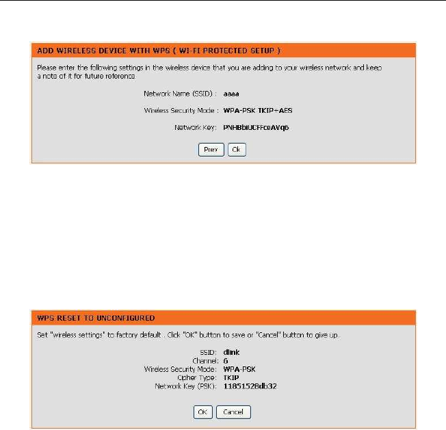
DSL-2750U/DSL-2750B User manual
It displays the current wireless settings and you can manually enter the settings in
the wireless device that’s to be added in the wireless network.
3.2.3.3 Manual Wireless Setup
If you want to configure the Internet settings of you new D-Link Router manually, click
Manual Wireless Connection Setup. It will redirect to 3.3.1 Wireless Settings.
3.2.3.4 Wireless WPS
In Wireless Connection page, Click Reset to Unconfigured, the page shown in the
following figure appears.
Once the “Reset to Unconfigured” button is clicked, the “wireless settings” will be
reset to factory default, other settings will remain unchanged.
3.2.4 Local Network
You can configure the LAN IP address according to the actual application. The preset
IP address is 192.168.1.1. You can use the default settings and DHCP service to
manage the IP settings for the private network. The IP address of the device is the
base address used for DHCP. To use the device for DHCP on your LAN, the IP ad-
dress pool used for DHCP must be compatible with the IP address
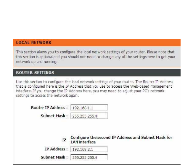
DSL-2750U/DSL-2750B User manual
of the device. The IP address available in the DHCP IP address pool changesauto-
matically if you change the IP address of the device. You can also enable the second-
ary LAN IP address. The two LAN IP addresses must be in different networks. Choose
Setup > Local Network. The Local Network page shown in thefollowing figure ap-
pears.
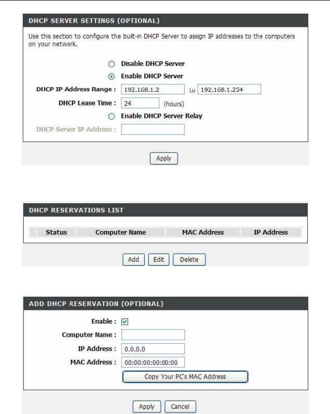
By default, Enable DHCP Server is selected for the Ethernet LAN interface of the
device. DHCP service supplys IP settings to workstations configured to automatically
obtain IP settings that are connected to the device through the Ethernet port. When
the device is used for DHCP, it becomes the default gateway for DHCP client con-
nected to it. If you change the IP address of the device, you must also change the
range of IP addresses in the pool used for DHCP on the LAN. The IP address pool
can contain up to 253 IP addresses.
DSL-2750U/DSL-2750B User manual
Click Apply to save the settings. In the Local Network page, you can assign IP addresses
on the LAN to specificindividual computers based on their MAC addresses.
Click Add to add static DHCP (optional). The page shown in the following figure appears.

DSL-2750U/DSL-2750B User manual
Select Enable to reserve the IP address for the designated PC with the configured
MAC address. The Computer Name helps you to recognize the PC with the MAC
address. For example, Father’s Laptop. Click Apply to save the settings. After the
DHCP reservation is saved, the DHCP reservations list displays theconfiguration. If
the DHCP reservations list table is not empty, you can select one or more itemsand
click Edit or Delete.
3.2.5 Time and Date
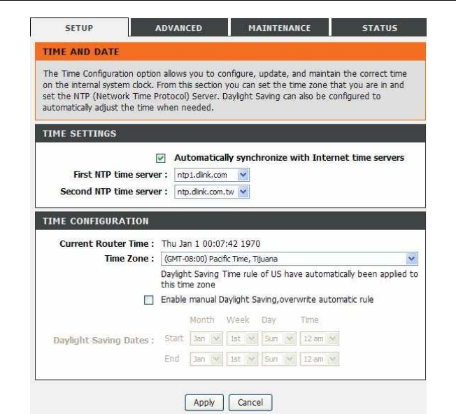
Choose Setup > Time and Date. The page shown in the following figure appears.
DSL-2750U/DSL-2750B User manual
In the Time and Date page, you can configure, update, and maintain the correct time on
the internal system clock. You can set the time zone that you are in andthe network time
protocol (NTP) server. You can also configure daylight saving toautomatically adjust the
time when needed. Select Automatically synchronize with Internet time servers. Select
the specific time server and the time zone from the corresponding drop-down lists. Select
Enable Daylight Saving if necessary. Set the daylight as you want. Click Apply to save
the settings.
DSL-2750U/DSL-2750B User manual
Note: The country selection mode is for non-US modes only and is not
available to the US mode
3.2.6 3G Internet Setup
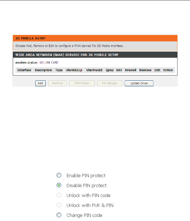
Choose Advanced Setup > 3G Internet Setup , and the following page appears.
This page is used to configure the 3G connection. If you want to access the Internet
through a 3G connection, a 3G network card is required. Connect the 3G network card to
the USB interface of the Router.
Note: (only support DWM-152 & DWM-156 3G network card)
If the 3G network card is installed, you may click the button on the Action column to
establish or disconnect the 3G connection.
Information: Click this button it to display the information of the 3G network card.
Upload Driver: For an un-supported USB dongle, click this button to upload the
new driver for USB support. The driver is a text file.
Pin Manage: Click this button to manage the PIN.
The following modes of PIN management are shown.
Enable PIN protect: If you enable it, you need to enter the PIN code when re-
booting or inserting the USB device.
Unlock with PIN code: If you disable it, you need to enter the PIN code when us-
ing a 3G device.
Unlock with PUK & PIN: If you disable it, you need to enter the PUK code when
failing to enter the correct PIN code 3 times.
Change PIN code: Choose this to change the PIN code.
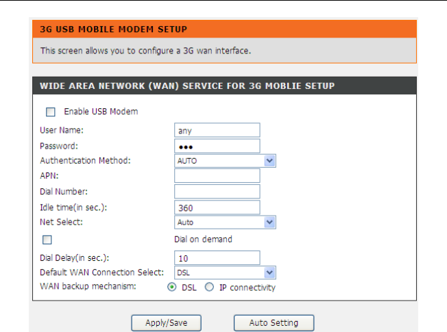
Click Add in the 3G Mobile Setup to display the following page.
DSL-2750U/DSL-2750B User manual
Default settings for Username, Password, Authentication method, APN, and Dial Number
are to be set.
In this page, you are allowed to configure the settings of the 3G USB modem.
Enable USB Modem:
If you want to access the Internet through the 3G network
card, you must enable the USB modem.
User Name:
Username provided by your 3G ISP.
Password: Password provided by your 3G ISP.
Authentication Method: Select a proper authentication method from the drop-
down list. You can select Auto, PAP, CHAP, or MSCHAP.
APN: APN (Access Point Name) is used to identify the service type. Enter the APN
provided by your 3G ISP.
Dial Number:
Enter the dial number provided by your 3G ISP.
Idle time (in sec.): If there is no traffic for the preset time, the 3G will disconnect
automatically.
Net Select: Select the 3G network that is available.You may select EVDO,
WCDMA, CDMA2000, TD-SCDMA, GSM, or Auto.
Dial on demand: Within the preset time, if the modem does not detect data flow ,
the modem automatically stops the 3G connection. Once it detects data flow (e.g.
access to a webpage), the modem restarts the 3G dialup.
Dial Delay (in sec.): The 3G delays dial after the DSL is disconnected.
Default WAN Connection Select: You can select DSL or 3G from the drop-down
list.
WAN backup mechanism: The 3G connection is used as backup for the DSL
connection.
– DSL: If the DSL is disconnected, the 3G starts to dial.
– IP connectivity: If the system fails to ping the specified IP ad-
dress, the 3G starts to dial.
After adding the settings, click the Apply/Save button to save the settings.
You may also click the auto setting button to automatically configure the 3G connection.
After clicking the Apply/Save button, the settings will take effect.
Note:
When there is no DSL WAN connection, insert the 3G network card, and the system
will perform a dial-up automatically. If the DSL WAN connection and the 3G connec-
tion coexist, the DSL WAN connection takes priority over the 3G connection. When
the DSL WAN connection starts to perform a dial-up, the 3G connection will be dis-
connected. If the DSL WAN connection has been established, you may manually
perform a 3G dial-up, and then the DSL WAN connection will be disconnected.
DSL-2750U/DSL-2750B User manual
34
3.2.7 Logout
Choose Setup > Logout. The page shown in the following figure appears. In this page,
you can log out of the configuration page.
3.3 Advanced
This section includes advanced features used for network management, security and
administrative tools to manage the device. You can view status and other information that
are used to examine performance and troubleshoot.
3.3.1 Wireless Settings
This function is used to modify the standard 802.11g wireless radio settings. It is recom-
mend not to change the default settings, because incorrect settings may impair the per-
formance of your wireless radio. The default settings provide the best wireless radio per-
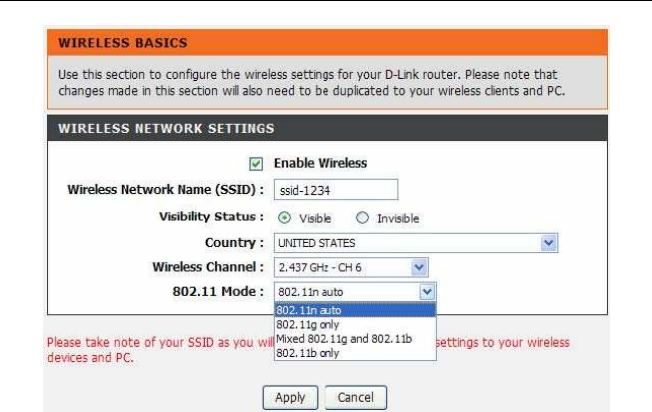
formance in most environments. Choose ADVANCED > Wireless Settings. The page
shown in the following figure appears.
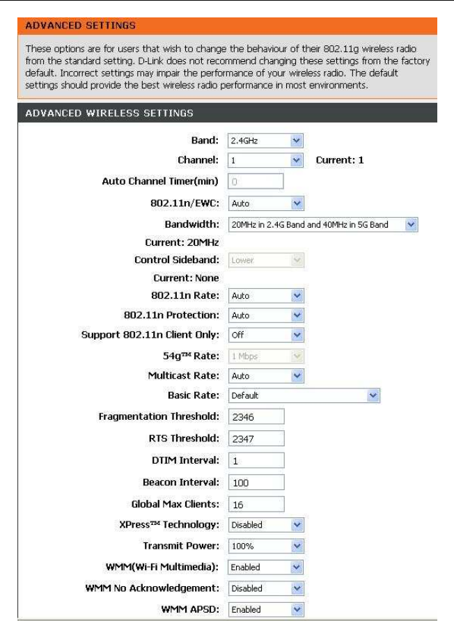
3.3.1.1 Wireless Basics
In the Wireless Settings page, click Wireless Basic, the page shown in the following
figure appears. In this page, you can configure the parameters of wireless LAN clients that
may connect to the device.
DSL-2750U/DSL-2750B User manual
Enable Wireless: Select this to turn Wi-Fi on and off.
Wireless Network Name (SSID): The Wireless Network Name is a unique name
that identifies a network. All devices on a network must share the same wireless
network name in order to communicate on the network. If you decide to change
the wireless network name from the default setting, enter your new wireless net-
work name in this field.
Visibility Status: You can select Visible or Invisible.
Country: Select the country from the drop-down list.
Wireless Channel: Select the wireless channel from the pull-down menu. It is
different for different countries.
802.11 Mode: Select the appropriate 802.11 mode based on the wireless clients
in your network. The drop-down menu options are 802.11n auto, 802.11g only,
Mixed 802.11g and 802.11b, or 802.11b only.
Click Apply to save the settings.
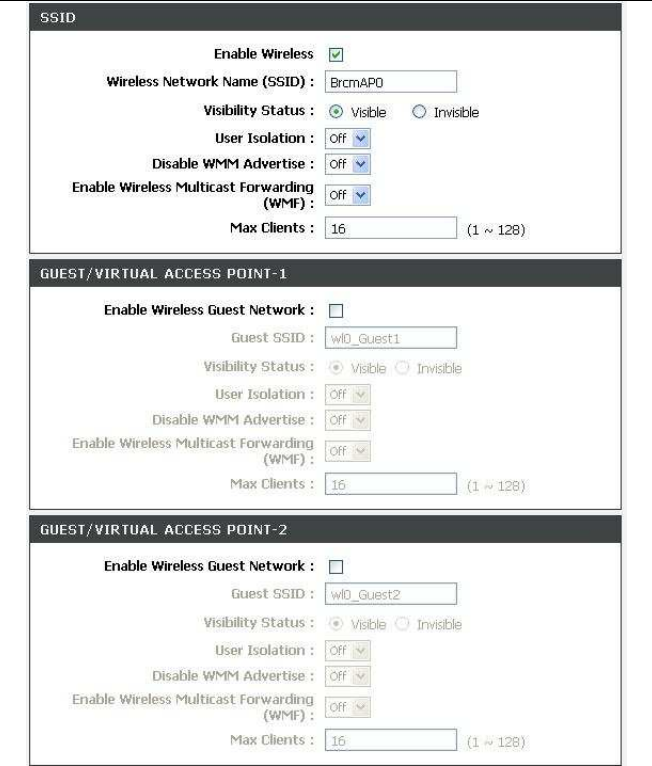
3.3.1.2 Advanced Settings
In the Wireless Settings page, click Advanced settings, the page shown in the follow-
ing figure appears.
DSL-2750U/DSL-2750B User manual
DSL-2750U/DSL-2750B User manual
DSL-2750U/DSL-2750B User manual
Band: Select using wireless frequency band range. The radio frequency remains
at 2.4GHz.
Channel: Enter the appropriate channel to correspond with your network settings.
All devices in your wireless network must use the same channel in order to work
correctly. This router supports auto channeling functionality.
Auto Channel Timer(min): Specifies the timer of auto channelling.
802.11n/EWC: Select disable or Auto.
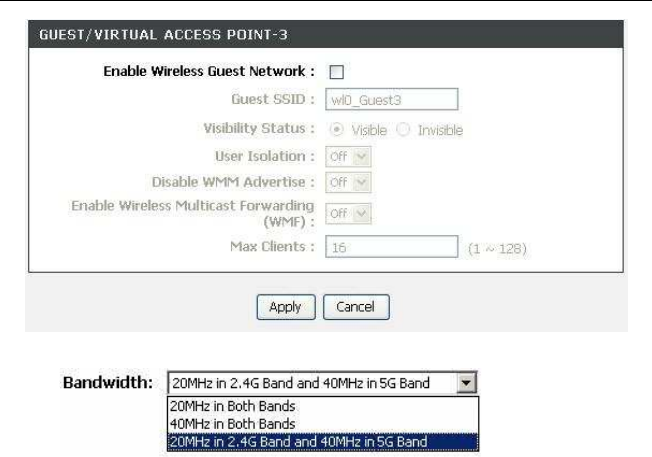
Bandwidth: You can select the bandwidth from the drop-down list.
802.11n Rate/54g™ Rate: Select the transmission rate for the network. The rate of
data transmission should be set depending on the speed of your wireless network.
You can select from a range of transmission speeds, or you can select Auto to
have the Router automatically use the fastest possible data rate and enable the
Auto-Fallback feature. Auto-Fallback will negotiate the best possible connection
speed between the Router and a wireless client. The default value is Auto.

DSL-2750U/DSL-2750B User manual
802.11n Protection: The 802.11n standards provide a protection method ,so
802.11b/g and 802.11n devices can co-exist in the same network without “speak-
ing” at the same time.
Support 802.11n Client Only: Only stations that are onfigured in 802.11n mode
can associate.
Multicast Rate: Select the multicast transmission rate for the network. The rate of
data transmission should be set depending on the speed of your wireless network.
You can select from a range of transmission speeds, or you can select Auto to
have the Router automatically use the fastest possible data rate and enable the
Auto-Fallback feature. Auto-Fallback will negotiate the best possible connection
speed between the Router and a wireless client. The default value is Auto.
Basic Rate: Select the basic transmission rate ability for the AP.
Fragmentation Threshold: Packets that are larger than this threshold are frag-
mented into multiple packets. Try to increase the fragmentation threshold if you
encounter high packet error rates. Do not set the threshold too low, since this can
result in reducing networking performance.
RTS Threshold: This value should remain at its default setting of 2347.Should you
encounter inconsistent data flow, only minor reductions are recommended. Should
you encounter inconsistent data flow, only minor reduction of the default value,
2347 is recommended. If a network packet is smaller than the preset RTS thre-
shold size, the RTS/CTS mechanism will not be enabled. The Router sends Re-
quest to Send (RTS) frames to a particular receiving station and negotiates the
sending of a data frame. After receiving an RTS, the wireless station responds with
a Clear to Send (CTS) frame to acknowledge the right to begin transmission. The
RTS Threshold value should remain at its default value of 2347

DSL-2750U/DSL-2750B User manual
DTIM Interval: (Delivery Traffic Indication Message) Enter a value between 1 and
255 for the Delivery Traffic Indication Message (DTIM.) A DTIM is a countdown in-
forming clients of the next window for listening to broadcast and multicast mes-
sages.
Beacon Interval: A beacon is a packet of information that is sent from a connected
device to all other devices where it announces its availability and readiness. A
beacon interval is a period of time (sent with the beacon) before sending the bea-
con again. The beacon interval may be adjusted in milliseconds (ms). Default (100)
is recommended.
XPress™ Technology: Select Enabled or Disabled. This is a special accelerating
technology for IEEE802.11g. The defaule is Disabled.
Transmit Power: Adjust the transmission range here. This tool can be helpful for
security purposes if you wish to limit the transmission range.
WMM (Wi-Fi Multimedia): Select whether WMM is enable or disabled. Before you
disable WMM, you should understand that all QoS queues or traffic classes related
to wireless do not take effect.
WMM No Acknowledgement: Select whether ACK in WMM packet. By default,
the 'Ack Policy' for each access category is set to Disabled, meaning that an ac-
knowledge packet is returned for every packet received. This provides a more reli-
able transmission but increases traffic load, which decreases performance. To
disable the acknowledgement can be useful for Voice, for example, where speed of
transmission is important and packet loss is tolerable to a certain degree.
WMM APSD: APSD is short for automatic power save delivery, Selecting Enabled
will make it very low power consumption. WMM Power Save is an improvement to
the 802.11e amendment adding advanced power management functionality to
WMM.
Enable Wireless: Select this to turn Wi-Fi on and off.

DSL-2750U/DSL-2750B User manual
Wireless Network Name (SSID): The Wireless Network Name is a unique name
that identifies a network. All devices on a network must share the same wireless
network name in order to communicate on the network. If you decide to change the
wireless network name from the default setting, enter your new wireless network
name in this field.
Visibility Status: You can select Visible or Invisible.
User Isolation: When many clients connect to the same access point, they can
access each other. If you want to disable the access between clients which con-
nect the same access point, you can select on to enable this service.
Max Clients: Specifies maximum wireless client stations to be enble to link with
AP. Once the clients exceed the max vlaue, all other clients will be refused.
GUEST/VIRTUAL ACCESS POINT: If you want to make Guest/Virtual network
function be available, you can set the parameters below.
These settings are only for more technically advanced users who have sufficient know-
ledge about wireless LAN. Do not change these settings unless you know the effect of
changes on the device.
Click Apply to save the settings.
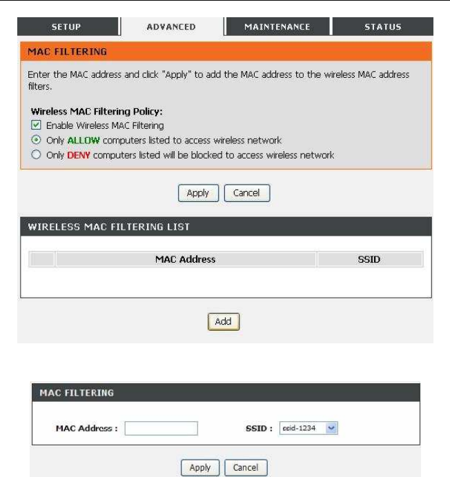
3.3.1.3 MAC Filtering
In the Wireless Settings page, click MAC Filtering, the page shown in thefollowing fig-
ure appears. In this page, you can allow or deny users access the wireless router based
ontheir MAC address.
DSL-2750U/DSL-2750B User manual
Click Add, the page shown in the following figure appears.
3.3.1.4 Security Settings
In the Wireless Settings page, click Security Settings. The page shown in the follow-
ing figure appears.
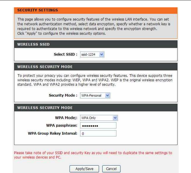
DSL-2750U/DSL-2750B User manual
Select the SSID that you want to configure from the drop-down list. Select the en-
cryption type from the Security Mode drop-down list.You can selectNone, WEP,
WPA-Personal and WPA-Enterprise. If you select WEP, the page shown in the fol-
lowing figure appears.
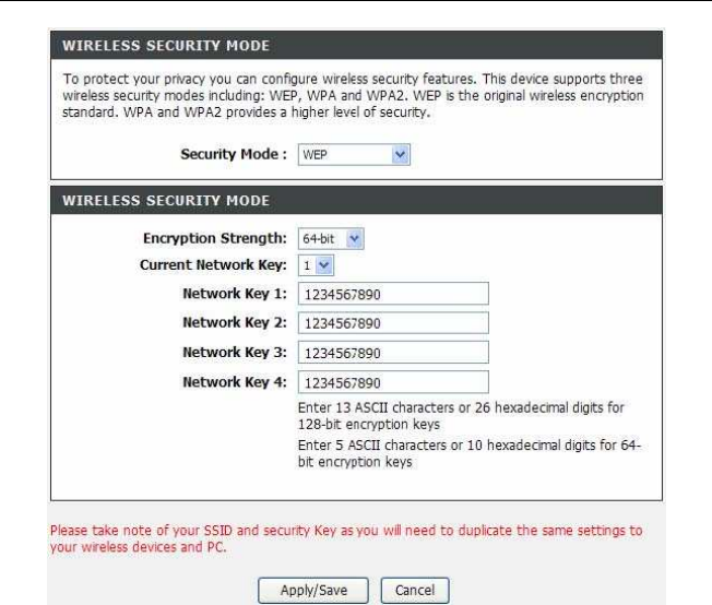
DSL-2750U/DSL-2750B User manual
WEP (Wireless Encryption Protocol) encryption can be enabled for securityand
privacy. WEP encrypts the data portion of each frame transmitted from thewireless
adapter using one of the predefined keys.The router offers 64 or 128 bit encryption
with four keys available. Select Encryption Strength from the drop-down menu.
(128 bit is stronger than 64 bit) Enter the key into the Network Key field 1~4. (Key
length is outlined at the bottomof the window.)Click Apply/Save to save the settings.
If you select WPA-Personal, the page shown in the following figure appears.
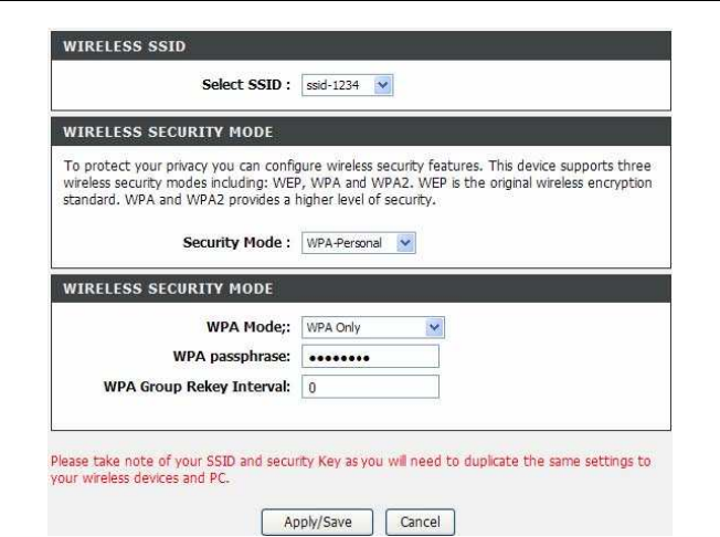
DSL-2750U/DSL-2750B User manual
WPA only(WPA-PSK) configuration is similar to WEP. The key length is between 8
to 63 ASCII characters or 64 hexadecimal digits. If you select WPA-Enterprise, the
page shown in the following figure appears.
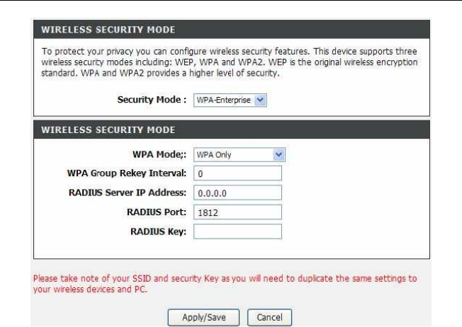
DSL-2750U/DSL-2750B User manual
You can only use WPA-enterprise if you have set up RADIUS server. This is the
WPA/WPA2 authentication with RADIUS server instead of pre-shared key.
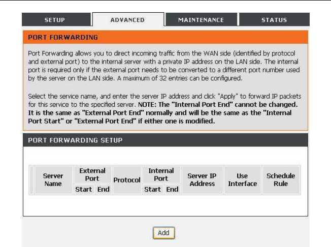
3.3.2 Port Forwarding
This function is used to open ports in your device and re-direct data through those
ports to a single PC on your network (WAN-to-LAN traffic). It allows remote users to
access services on your LAN, such as FTP for file transfers or SMTP and POP3 for
e-mail. The device accepts remote requests for these services at your global IP ad-
dress. It uses the specified TCP or UDP protocol and port number, and redirects
these requests to the server on your LAN with the LAN IP address you specify. Note
that the specified private IP address must be within the available range of the subnet
where the device is in. Choose ADVANCED > Port Forwarding. The page shown in
the following figure appears.
DSL-2750U/DSL-2750B User manual
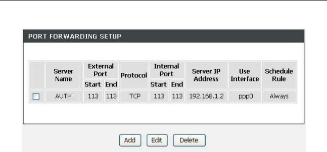
Click Add to add a virtual server.
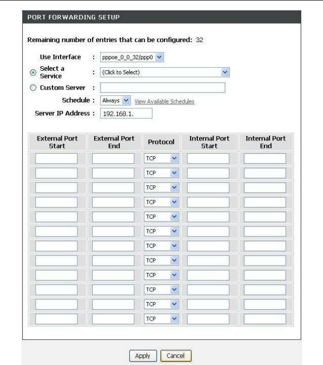
DSL-2750U/DSL-2750B User manual
Select a service for a preset application, or enter a name in the Custom Serverfield.
Enter an IP address in the Server IP Address field, to appoint the correspondingPC
to receive forwarded packets. The Ports show the ports that you want to open on the
device. The TCP/UDPmeans the protocol type of the opened ports.
DSL-2750U/DSL-2750B User manual
Click Apply to save the settings. The page shown in the following figure appears. A
virtual server is added.
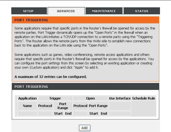
3.3.3 Port Triggering
Some applications require that specific ports in the firewall of the device are open
for the remote parties to access. Application rules dynamically open the firewall
ports when an application on the LAN initiates a TCP/UDP connection to a remote
party using the trigger ports. The device allows the remote party from the WAN side
to establish new connections back to the application on the LAN side using the
firewall ports. A maximum of 32 entries can be configured.
DSL-2750U/DSL-2750B User manual
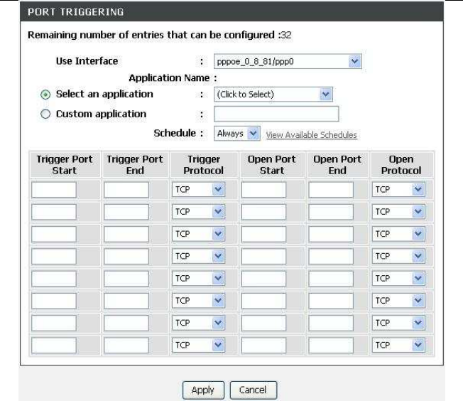
Click Add to add a new Port Trigger.
52
DSL-2750U/DSL-2750B User manual
Click the Select an application drop-down menu to choose the application you want
to setup for port triggering. When you have chosen an application the default Trigger
settings will populate the table below. If the application you want to setup isn’t listed,
click the Custom application radio button and type in a name for the trigger in the
Custom application field. Configure the Trigger Port Start, Trigger Port End, Trig-
ger Protocol, Open Port Start, Open Port End and Open Protocol settings for the
port trigger you want to configure. When you have finished click the Apply button.
DSL-2750U/DSL-2750B User manual
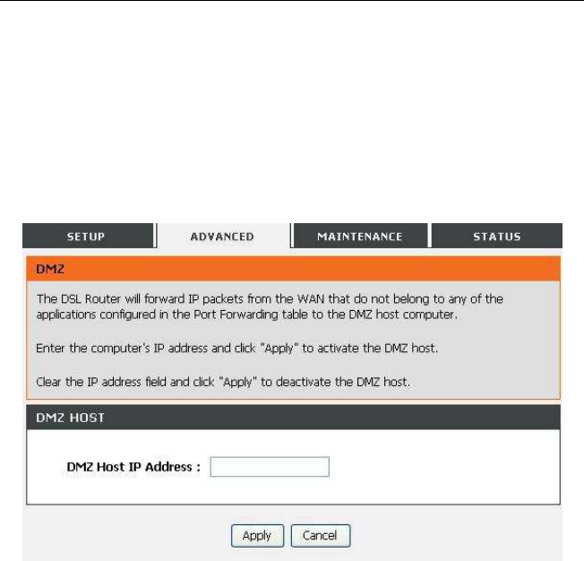
3.3.4 DMZ
Since some applications are not compatible with NAT, the device supports the use of a
DMZ IP address for a single host on the LAN. This IP address is not protected by NAT
and it is visible to agents on the Internet with the correct type of software. Note that any
client PC in the DMZ is exposed to various types of security risks. If you use the DMZ,
take measures (such as client-based virus protection) to protect the remaining client
PCs on your LAN from possible contamination through DMZ. Choose ADVANCED >
DMZ. The page shown in the following figure appears.
Click Apply to save the settings.
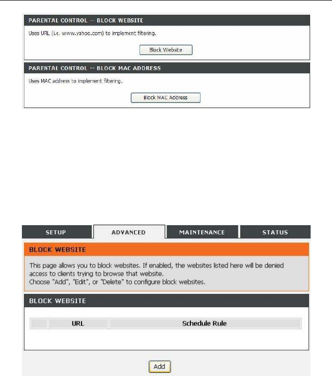
3.3.5 Parental Control
Choose ADVANCED > Parental Control. The Parent Control page shown in the fol-
lowing figure appears.
DSL-2750U/DSL-2750B User manual
This page provides two useful tools for restricting the Internet access. Block Web-
sites allows you to quickly create a list of all websites that you wish to stop users
from accessing. Block MAC Address allows you to control when clients or PCs
connected to the device are allowed to access the Internet.
3.3.5.1 Block Website
In the Parent Control page, click Block Website. The page shown in the following
figure appears.
Click Add. The page shown in the following page appears.
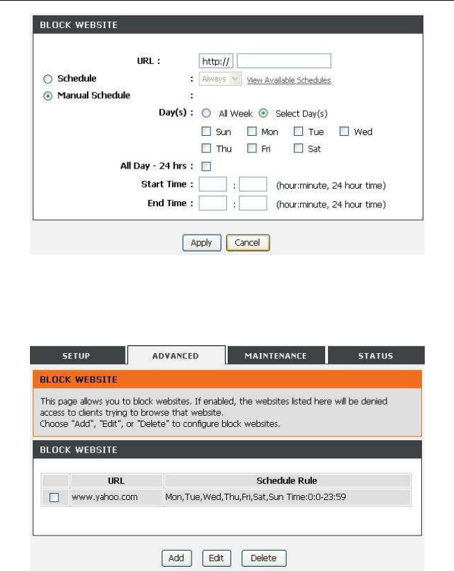
DSL-2750U/DSL-2750B User manual
Enter the website in the URL field. Select the Schedule from drop-down list, or select
Manual Schedule and select the corresponding time and days. Click Apply to add
the website to the BLOCK WEBSITE table.The page shown in the following figure
appears.
DSL-2750U/DSL-2750B User manual
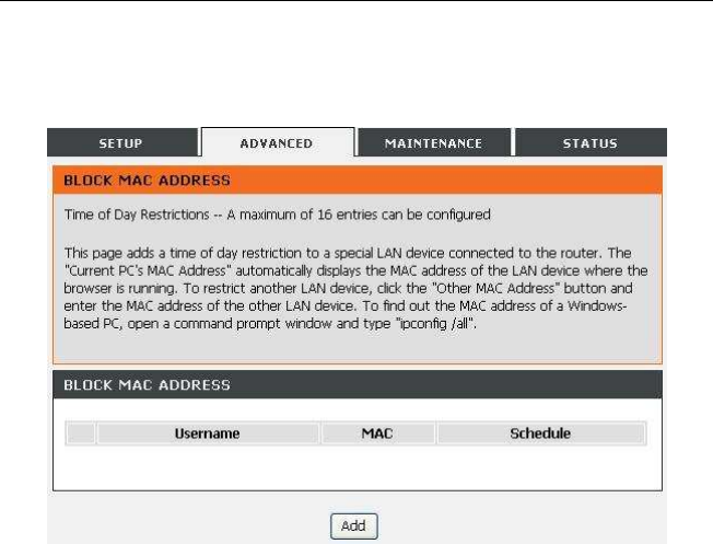
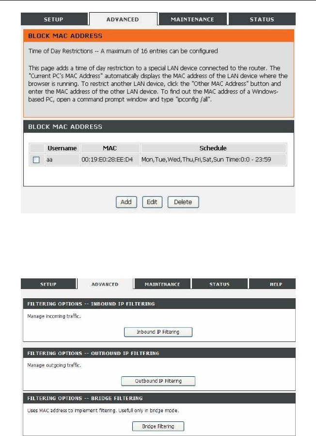
3.3.5.2 Block MAC Address
In the Parent Control page, click Block MAC Address. The page shown in the fol-
lowing figure appears.
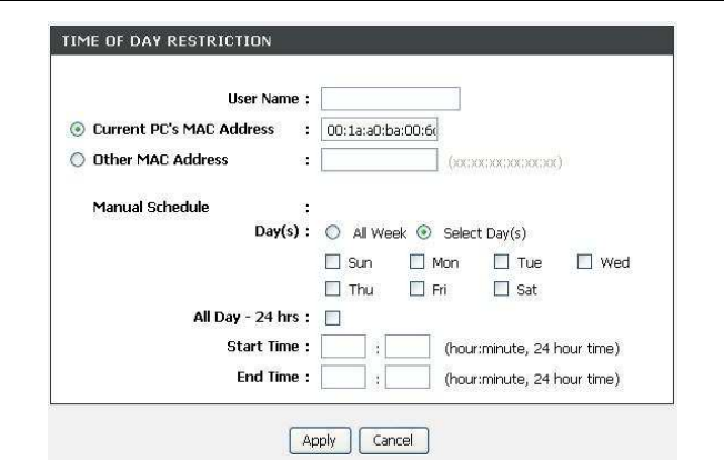
Click Add. The page shown in the following figure appears.
DSL-2750U/DSL-2750B User manual
Enter the use name and MAC address and select the corresponding time and days.
Click Apply to add the MAC address to the BLOCK MAC ADDRESS table. The
page shown in the following figure appears.
DSL-2750U/DSL-2750B User manual
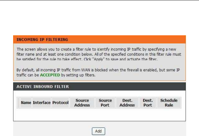
3.3.6 Filtering Options
Choose ADVANCED > Filtering Options. The Filtering Options page shown in the
following figure appears.
DSL-2750U/DSL-2750B User manual
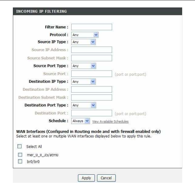
3.3.6.1 Inbound IP Filtering
In the Filtering Options page, click Inbound IP Filtering. The page shown in the fol-
lowing figure appears.
Click Add to add an inbound IP filter. The page shown in the following figure appears.
DSL-2750U/DSL-2750B User manual

DSL-2750U/DSL-2750B User manual
Enter the Filter Name and specify at least one of the following criteria: protocol,
source/destination IP address, subnet mask, and source/destination port. Click Apply to
save the settings.
Note:
The settings only apply when the firewall is enabled.
The ACTIVE INBOUND FILTER shows detailed information about each created inbound
IP filter.
DSL-2750U/DSL-2750B User manual
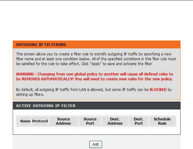
3.3.6.2 Outbound IP Filtering
By default, all outgoing IP traffic from the LAN is allowed. The outbound filter allows you to
create a filter rule to block outgoing IP traffic by specifying a filter name and at least one
condition. In the Filtering Options page, click Outbound IP Filtering. The page shown in
the following figure appears.
Click Add to add an outbound IP filter. The page shown in the following figure appears.
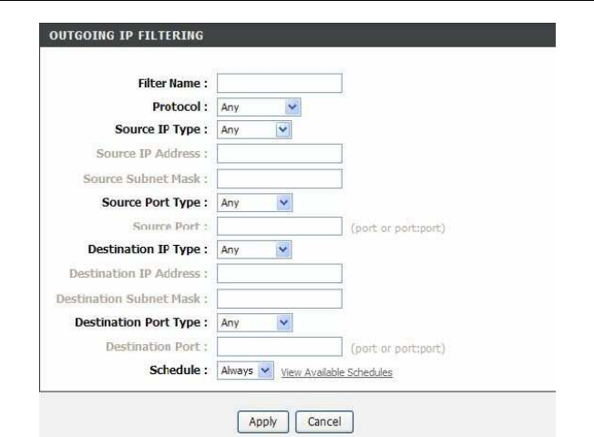
DSL-2750U/DSL-2750B User manual
Enter the Filter Name and specify at least one of the following criteria: proto-
col,source/destination IP address, subnet mask, and source/destination port. Click
Apply to save the settings. The ACTIVE OUTBOUND IP FILTER shows detailed in-
formation about each created outbound IP filter..
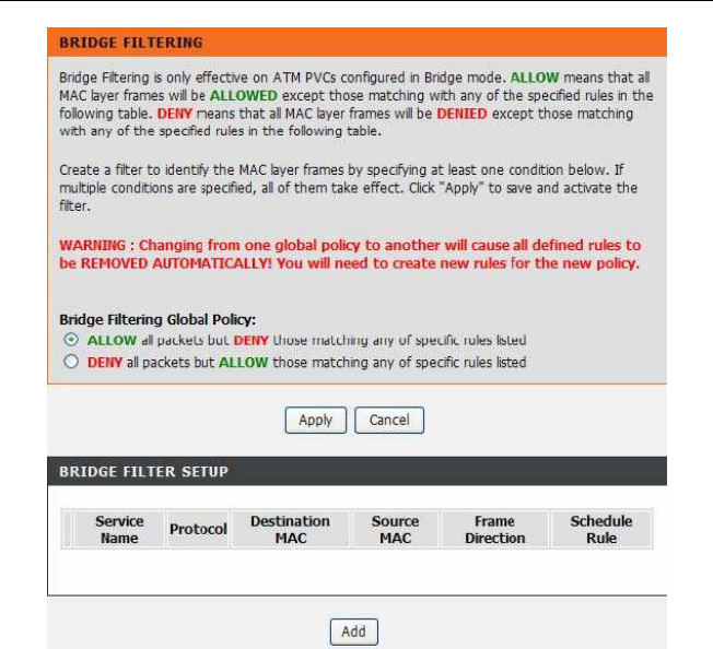
3.3.6.3 Bridge Filtering
In the Filtering Options page, click Bridge Filtering. The page shown in the follow-
ing figure appears.This page is used to configure bridge parameters. In this page,
you can change the settings or view some information of the bridge and its attached
ports.
DSL-2750U/DSL-2750B User manual
Click Add to add a bridge filter. The page shown in the following figure appears.
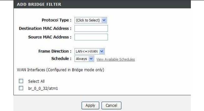
DSL-2750U/DSL-2750B User manual
Click Apply to save the settings.
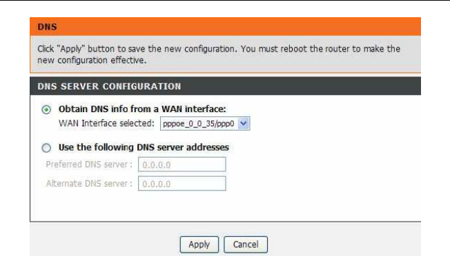
3.3.7 DNS
Domain name system (DNS) is an Internet service that translates domain names into
IP addresses. Because domain names are alphabetic, they are easier to remember.
The Internet, however, is actually based on IP addresses. Each time you use a domain
name, a DNS service must translate the name into the corresponding IP address. For
example, the domain name www.example.com might be translated to 198.105.232.4.
The DNS system is, in fact, its own network. If one DNS server does not know how to
translate a particular domain name, it asks another one, and so on, until the correct IP
address is returned. Choose ADVANCED > DNS. The page shown in the folllowin g
figure appears.
DSL-2750U/DSL-2750B User manual
DNS SERVER CONFIGURATION
If you are using the device for DHCP service on the LAN or if you are using DNS
servers on the ISP network, select Obtain DNS Info from a WAN interface. If you
have DNS IP addresses provided by your ISP, enter these IP addresses in the
available entry fields for the preferred DNS server and the alternate DNS server.
Click Apply to save the settings.
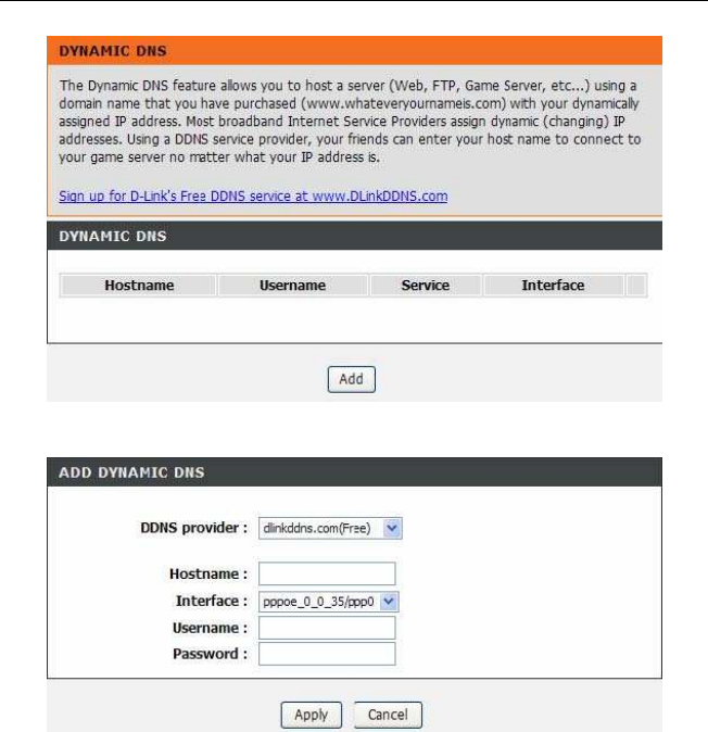
3.3.8 Dynamic DNS
The device supports dynamic domain name service (DDNS). The dynamic DNS ser-
vice allows a dynamic public IP address to be associated with a static host name in
any of the many domains, and allows access to a specified host from various loca-
tions on the Internet. Click a hyperlinked URL in the form of hostname.dyndns.org
and allow remote access to a host. Many ISPs assign public IP addresses using
DHCP, so locating a specific host on the LAN using the standard DNS is difficult. For
example, if you are running a public web server or VPN server on your LAN, DDNS
ensures that the host can be located from the Internet even if the public IP address
changes. DDNS requires that an account be set up with one of the supported DDNS
service providers (DyndDNS.org or dlinkddns.com). Choose ADVANCED > Dynam-
ic DNS. The page shown in the following page appears.
DSL-2750U/DSL-2750B User manual
Click Add to add dynamic DNS. The page shown in the following figure appears.
DDNS provider: Select one of the DDNS registration organizations from the
down-list drop.
Host Name: Enter the host name that you registered with your DDNS service pro-
vider.
Interface: Select the interface you want to use.
Username: Enter the user name for your DDNS account.
Password: Enter the password for your DDNS account. Click Apply to save the
settings.
DSL-2750U/DSL-2750B User manual
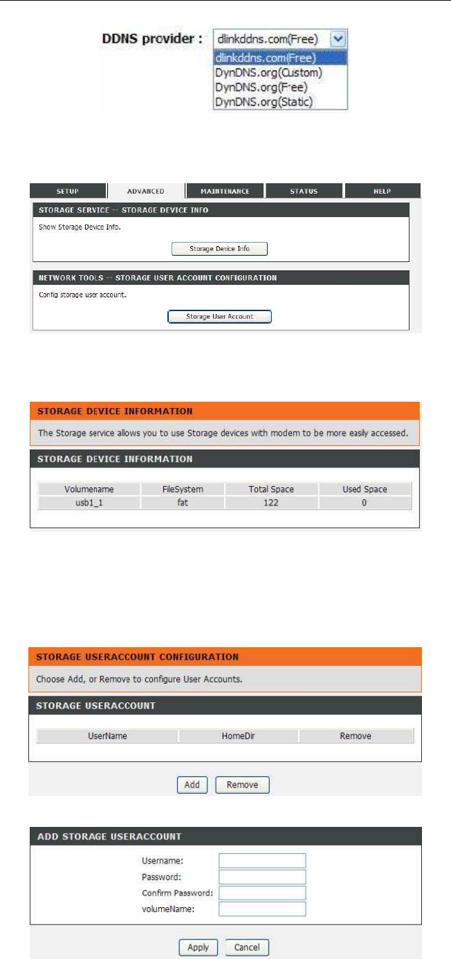
3.3.9 Storage Service
Choose ADVANCED > Storage Service. The Storage Service page shown in the fol-
lowing figure appears.
3.3.9.1 Storage Device Info
In the Storage Service page, click Storage Device Info. The page shown in the follow-
ing figure appears.
When you insert USB storage, this page will show the information of USB storage, such
as file system, total space and used space.
3.3.9.2 User Accounts
In the Storage Service page, click User Accounts. The page shown in the following
figure appears.
Click Add to add a user. The page shown in the following figure appears.
Username:set valid user that access CPE’s samba server
Password:user’s password
DSL-2750U/DSL-2750B User manual
Confirm Password:user’s password
volumeName:the directory you want to share
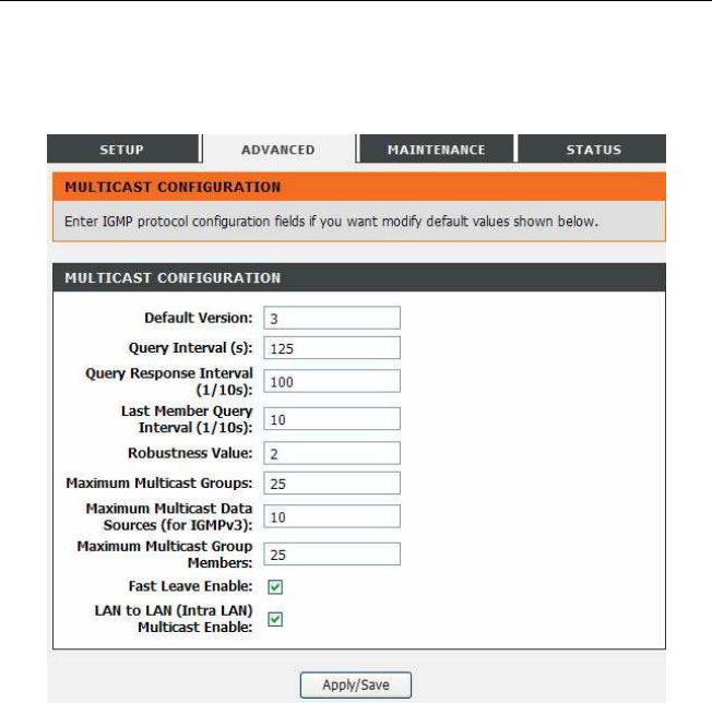
3.3.10 Multicast
Choose ADVANCED > Multicast. The page shown in the following figure appears.
Default Version:IGMP version
Query Interval(s):The query interval is the amount of time in seconds between IGMP
General Query messages sent by the router (if the router is the querier on this sub-
net)
Query Response Interval (1/10s): The query response interval is the maximum
amount of time in seconds that the IGMP router waits to receive a response to a
General Query message. The query response interval is the Maximum Response
Time field in the IGMP v2 Host Membership
Query message header. The default query response interval is 10 seconds and must
be less than the query interval

DSL-2750U/DSL-2750B User manual
Last Member Query Interval (1/10s): The last member query interval is the amount
of time in seconds that the IGMP router waits to receive a response to a
Group-Specific Query message. The last member queryinterval is also the amount of
time in seconds between successive Group-Specific Query messages.
Robustness Value: The robustness variable is a way of indicating howsusceptible
the subnet is to lost packets. IGMP can recover fromrobustness variable minus 1 lost
IGMP packets.
Maximum Multicast Groups:max multicast groups
Maximum Multicast Data Sources (for IGMPv3): max group datasources that want
to receive.
Maximum Multicast Group Members:Max member in one group
Fast Leave Enable: Enable or disable fast leave feature.
LAN to LAN (Intra LAN) Multicast Enable: Enable or disable Lan to Lan msulticast.
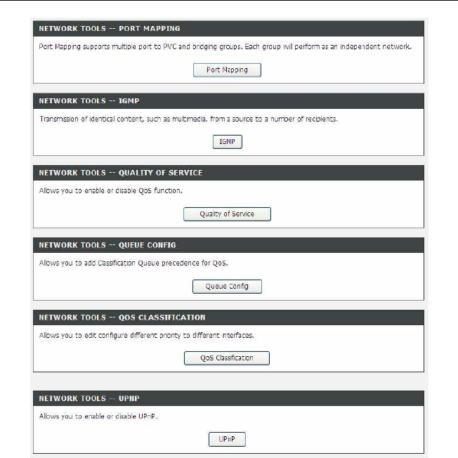
3.3.11 Network Tools
Choose ADVANCED > Network Tools. The page shown in the following figure appears.
DSL-2750U/DSL-2750B User manual
DSL-2750U/DSL-2750B User manual
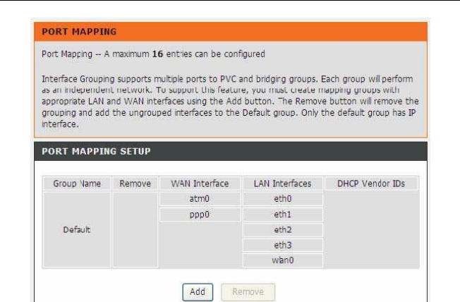
3.3.11.1 Port Mapping
Choose ADVANCED > Network Tools and click Port Mapping. The page shown in the
following figure appears. In this page, you can bind the WAN interface and the LAN in-
terface to the same group.
DSL-2750U/DSL-2750B User manual
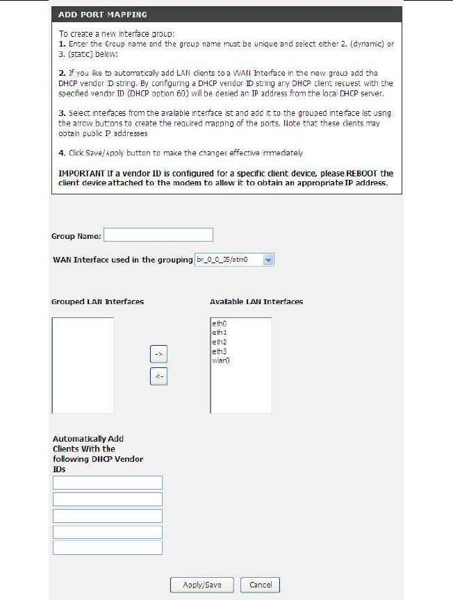
Click Add to add port mapping. The page shown in the following figure appears.
DSL-2750U/DSL-2750B User manual
DSL-2750U/DSL-2750B User manual
The procedure for creating a mapping group is as follows:
Step 1
Enter the group name.
Step 2
Select the WAN interface for your new group.
Step
3
Select LAN interfaces from the Available Interface list and click the
arrow button to add them to the grouped interface list, in order to create the
required mapping of the ports. The group name must be unique.
Step 4 Enter the option information of DHCP vendor IDs.
Step 5 Click Apply to save the settings.
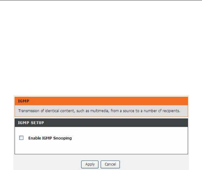
3.3.11.2 IGMP
Choose ADVANCED > Network Tools and click IGMP. The page shown in the fol-
lowing figure appears. When enable IGMP Snooping, the multicast data transmits
through the specific LAN port which has received the request report.
3.3.11.3 Quality of Service
Choose ADVANCED > Network Tools and click Quality of Service. The page shown
in the following figure appears.
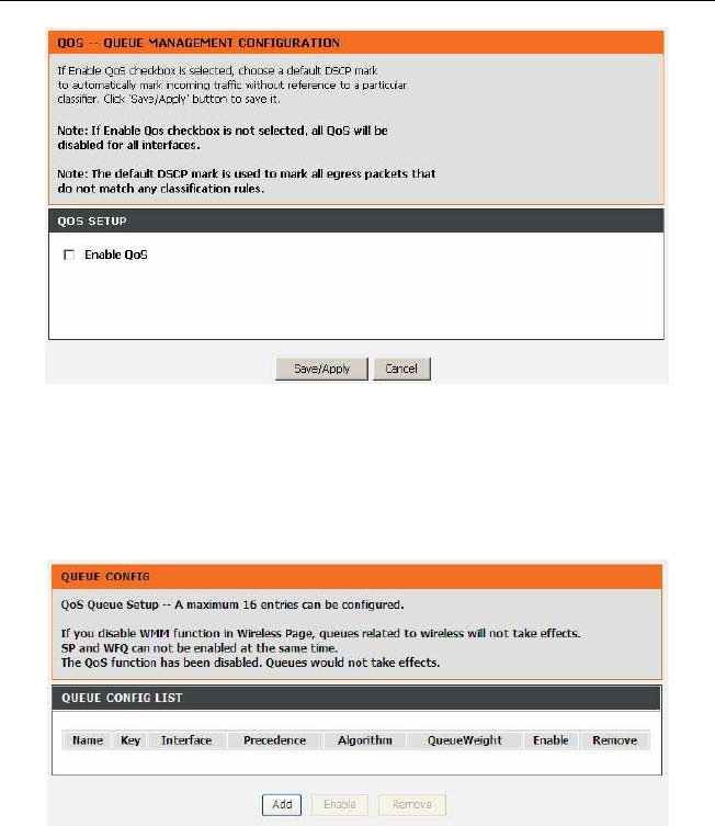
DSL-2750U/DSL-2750B User manual
In this page, you can enable/disable the QoS. Click Save/Apply to take the setting ef-
fect.
3.3.11.4 Queue Config
Choose ADVANCED > Network Tools and click Queue Config. The page shown in the
following figure appears.
Click Add. The page shown in the following figure appears.
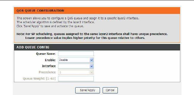
DSL-2750U/DSL-2750B User manual
Click Save/Apply to save the settings.
DSL-2750U/DSL-2750B User manual
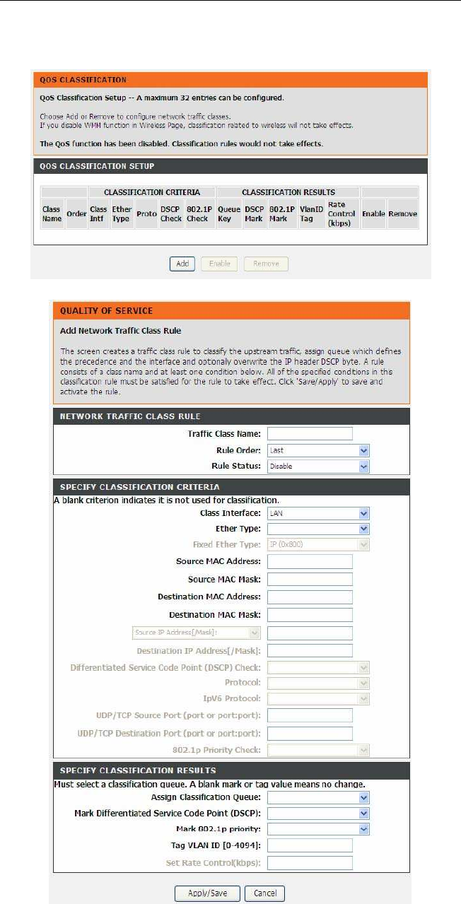
3.3.11.5 QoS Classification
Choose ADVANCED > Network Tools, and click QoS Classification, the page shown
in the following figure appears.This page allows you to config various classification.
Click Add. The page shown in the following figure appears.
DSL-2750U/DSL-2750B User manual
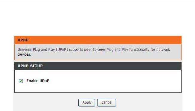
3.3.11.6 UPnP
Choose ADVANCED > Network Tools and click UPnP. The page shown in the follow-
ing figure appears.
In this page, you can configure universal plug and play (UPnP). The system acts as a
daemon after you enable UPnP. UPnP is used for popular audio visual software. It al-
lows automatic discovery of your device in the network. If you are concerned about
UPnP security, you can disable it. Block ICMP ping should be enabled so that the device
does not respond to malicious Internet requests. Click Apply to save the settings.
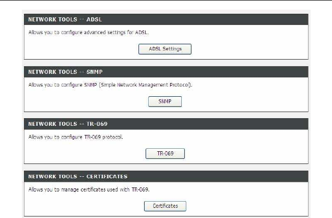
3.3.11.7 ADSL
Choose ADVANCED > Network Tools and click ADSL. The page shown in the follow-
ing figure appears.
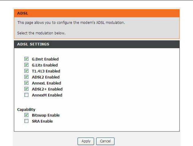
DSL-2750U/DSL-2750B User manual
In this page, you can select the DSL modulation. Normally, you can keep the factory de-
fault setting. The device negotiates the modulation mode with DSLAM. Click Apply to
save the settings.
DSL-2750U/DSL-2750B User manual
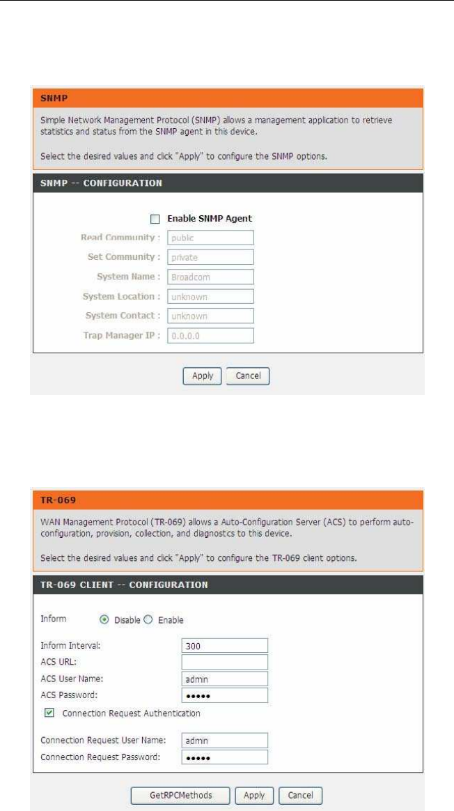
3.3.11.8 SNMP
Choose ADVANCED > Network Tools and click SNMP. The page shown in the follow-
ing figure appears. In this page, you can set SNMP parameters.
Click Apply to save the settings.
3.3.11.9 TR-069
Choose ADVANCED > Network Tools and click TR069. The page shown in the follow-
ing figure appears. In this page, you can configure the TR069 CPE.
WAN Management Protocol (TR-069) allows a Auto-Configuration Server (ACS)to
perform auto-configuration, provision, collection, and diagnostics to this device. In this
page, you may configure the parameters such as the ACS URL, ACSpassword, and
connection request user name. After finishing setting, click Apply to save and apply
the settings.
DSL-2750U/DSL-2750B User manual
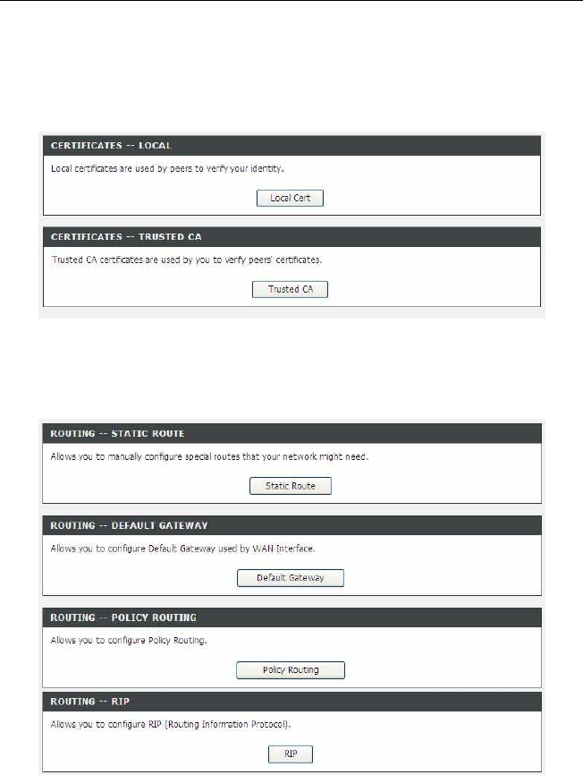
3.3.11.10 Certificates
Choose ADVANCED > Network Tools and click Certificates. The Certificates page
shown in the following figure appears. In this page, you can configure local certificate
and trusted certificate.
3.3.12 Routing
Choose ADVANCED > Routing.
The page shown in the following page appears.
DSL-2750U/DSL-2750B User manual
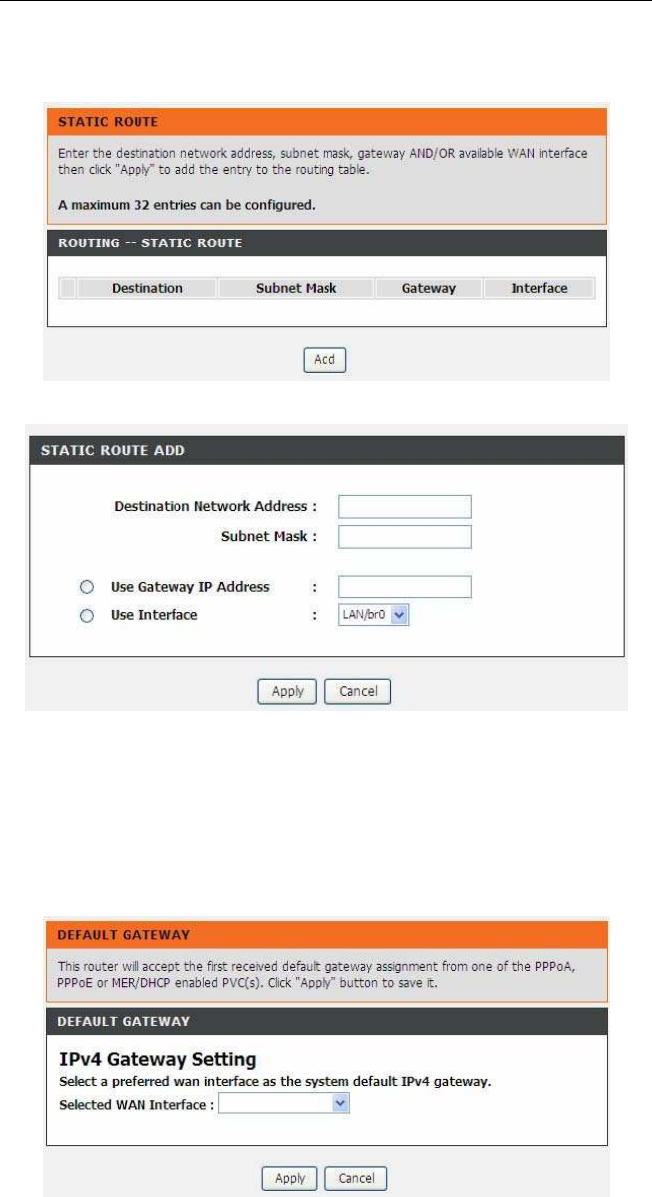
3.3.12.1 Static Route
Choose ADVANCED > Routing and click Static Route. The page shown in the follow-
ing figure appears. This page is used to configure the routing information. In this page,
you can add or delete IP routes.
Click Add to add a static route. The page shown in the following figure appears.
Destination Network Address: The destination IP address of the router.
Subnet Mask: The subnet mask of the destination IP address.
Use Gateway IP Address: The gateway IP address of the router.
Use Interface: The interface name of the router output port. You can click Use Ga-
teway IP Address or Use Interface.Click Apply to save the settings.
3.3.12.2 Default Gateway
Choose ADVANCED > Routing and click Default Gateway. The page shown in the fol-
lowing figure appears.
Select the WAN interface as your default gateway. Click Apply to save the settings.
DSL-2750U/DSL-2750B User manual
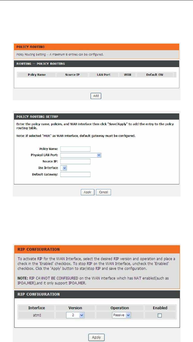
3.3.12.3 Policy Routing
Choose ADVANCED > Routing and click policy Routing.
The page shown in
the following figure appears. The policy route binds one WAN connection and one LAN
interface.
Click Add, the page shown in the following figure appears.
3.3.13 RIP
Choose ADVANCED > Routing and click RIP. The page shown in the following figure
appears. This page is used to select the interfaces on your device that use RIP and the
version of the protocol used.
If you are using this device as a RIP-enabled device to communicate with others using
the routing information protocol, enable RIP and click Apply to save the settings.
DSL-2750U/DSL-2750B User manual
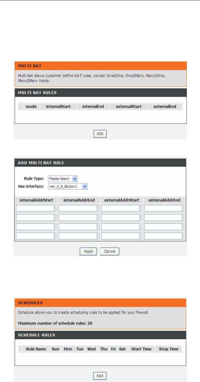
3.3.14 MultiNat
Network address translation (NAT) is the process of modifying network address informa-
tion in IP packet headers while in transit across a traffic routing device for the purpose of
remapping a given address space into another. The packets which source IP address
match between “internalStart” and “internalEnd” in the NAT table come to the router, the
router changes source IP of this packet by the IP address that set between “externalS-
tart” and “externalEnd”, then transmit the packet into Internet.
Click Add, the page shown in the following figure appears.
In this page, please select the proper type; select the proper Use interface, and configure
the other parameters in this page. After finishing setting, click Apply to save the settings.
3.3.15 Schedules
Choose ADVANCED > Schedules. The page shown in the following figure appears.
Click Add to add schedule rule. The page shown in the following figure appears.
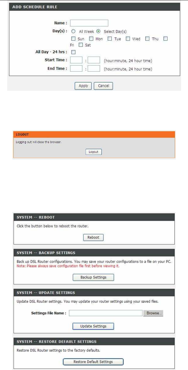
DSL-2750U/DSL-2750B User manual
Click Apply to save the settings.
3.3.16 Logout
Choose ADVANCED > Logout. The page shown in the following figure appears. In this
page, you can log out of the configuration page.
3.4 Maintenance
3.4.1 System
Choose MAINTENANCE > System. The System page shown in the following figure ap-
pears.
In this page, you can reboot device, back up the current settings to a file, restore the set-
tings from the file saved previously, and restore the factory defaultsettings. The buttons in
this page are described as follows:
Reboot: Reboot the device.
Backup Settings: Save the settings to the local hard drive. Select a location on your
computer to back up the file. You can name the configuration file.
Update settings: Click Browse to select the configuration file of device and click
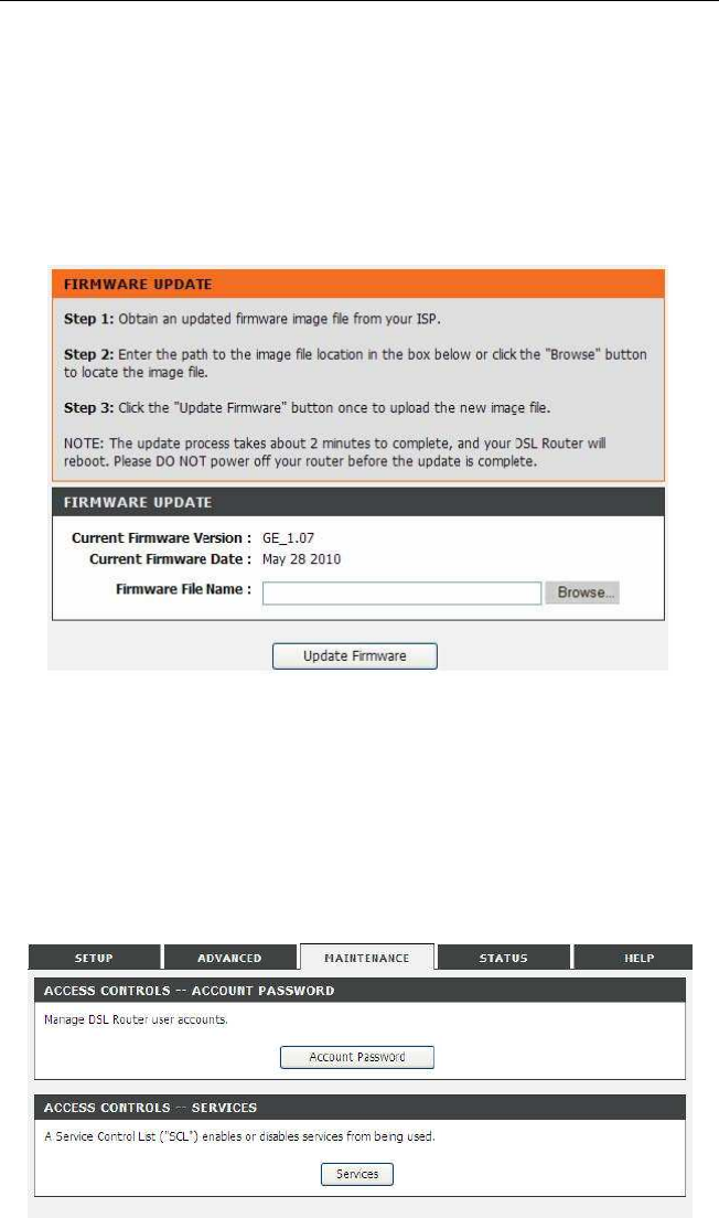
DSL-2750U/DSL-2750B User manual
Update Settings to begin restoring the device configuration..
Restore Default Settings: Reset the device to default settings.
Notice: Do not turn off your device or press the Reset button while an operation in this
page is in progress.
3.4.2 Firmware Update
Choose MAINTENANCE > Firmware Update. The page shown in the following figure
appears. In this page, you can upgrade the firmware of the device.
The procedure for updating the firmware is as follows:
Step 1 Click Browse…to search the file.
Step 2 Click Update Firmware to update the configuration file. The device loads the file
and reboots automatically.
Notice: Do not turn off your device or press the reset button while this procedure is in
progress.
3.4.3 Access Controls
Choose MAINTENANCE > Access Controls. The Access Controls page shown in the
following figure appears. The page contains Account Password, Services.
3.4.3.1 Account Password
In the Access Controls page, click Account Password. The page shown in the follow-
ing figure appears. In this page, you can change the password of the user and set time
for automatic logout.
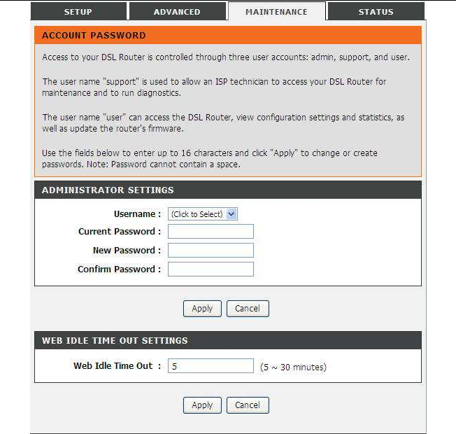
DSL-2750U/DSL-2750B User manual
You should change the default password to secure your network. Ensure that you
remember the new password or write it down and keep it in a safe and separate loca-
tion for future reference. If you forget the password, you need to reset the device to
the factory default settings and all configuration settings of the device are lost. Select
the Username from the drop-down list. You can select admin, support, or user.
Enter the current and new passwords and confirm the new password, to change the
password. Click Apply to apply the settings.
DSL-2750U/DSL-2750B User manual
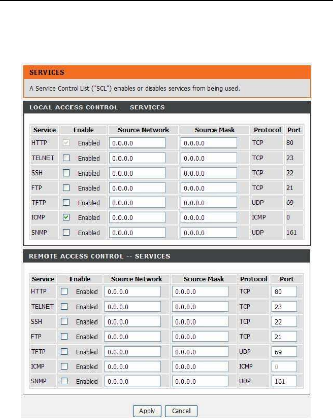
3.4.3.2 Services
In the Access Controls page, click Services. The page shown in the following figure
appears.
In this page, you can enable or disable the services that are used by the remote host. For
example, if telnet service is enabled and port is 23, the remote host can access the device
by telnet through port 23. Normally, you need not change the settings. Select the man-
agement services that you want to enable or disable on the LAN or WAN interface.
Click Apply to apply the settings.
Note:
If you disable HTTP service, you cannot access the configuration page of the
device any more.
DSL-2750U/DSL-2750B User manual
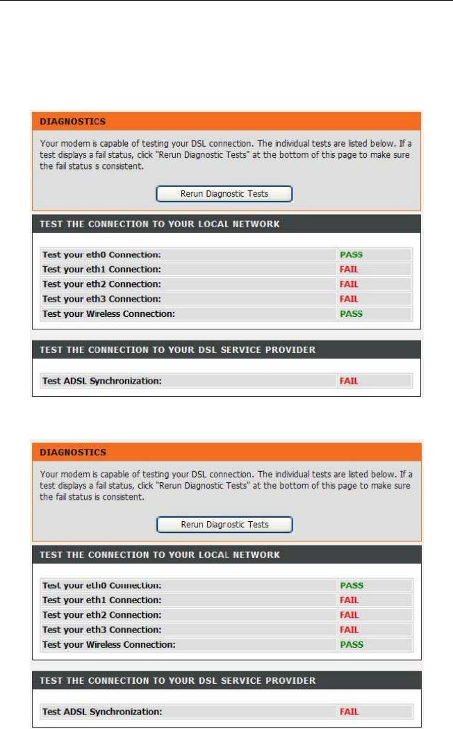
3.4.4 Diagnostics
Choose MAINTENANCE > Diagnostic. The page shown in the following figure appears.
In this page, you can test the device.
Click Return Diagnostics Test to run diagnostics. The page shown in the following figure
appears.
3.4.5 System Log
Choose MAINTENANCE > System Log. The System Log page shown in the following
figure appears.
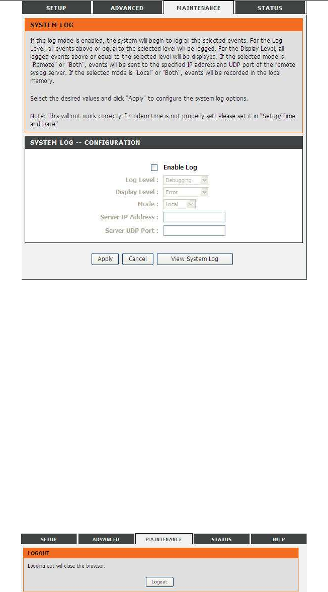
DSL-2750U/DSL-2750B User manual
This page displays event log data in the chronological manner. You can read theevent log
from the local host or send it to a system log server. Available eventseverity levels are as
follows: Emergency, Alert, Critical, Error, Warning, Notice, Informational and Debugging. In
this page, you can enable or disable the systemlog function. The procedure for logging the
events is as follows:
Step
1 Select
Enable Log
check box.
Step
2 Select the display mode from the
Mode
drop-down list.
Step
3 Enter the
Server IP Address
and
Server UDP Port
if the
Mode
is
set
to
Both
or
Remote
.
Step
4 Click Apply to apply the settings.
Step
5 Click
View System Log
to view the detail information of system log.
3.4.6 Logout
Choose MAINTENANCE > Logout. The page shown in the following figure appears. In
this page, you can log out of the configuration page.
3.5 Status
You can view the system information and monitor performance.
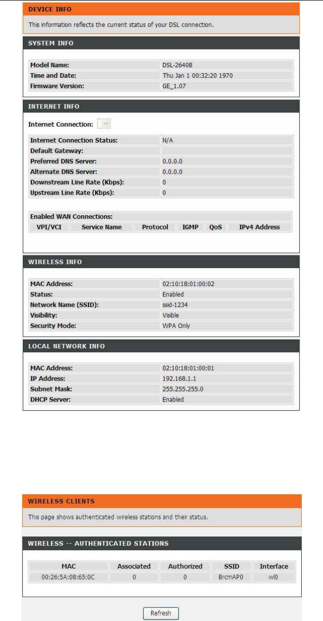
3.5.1 Device Info
Choose STATUS > Device Info. The page shown in the follow-
ing figure appears.
DSL-2750U/DSL-2750B User manual
The page displays the summary of the device status, including the system information,
WAN connection information, and local network information.
3.5.2 Wireless Clients
Choose STATUS > Wireless Clients. The page shown in the following figure appears.
The page displays authenticated wireless stations and their statuses.
DSL-2750U/DSL-2750B User manual
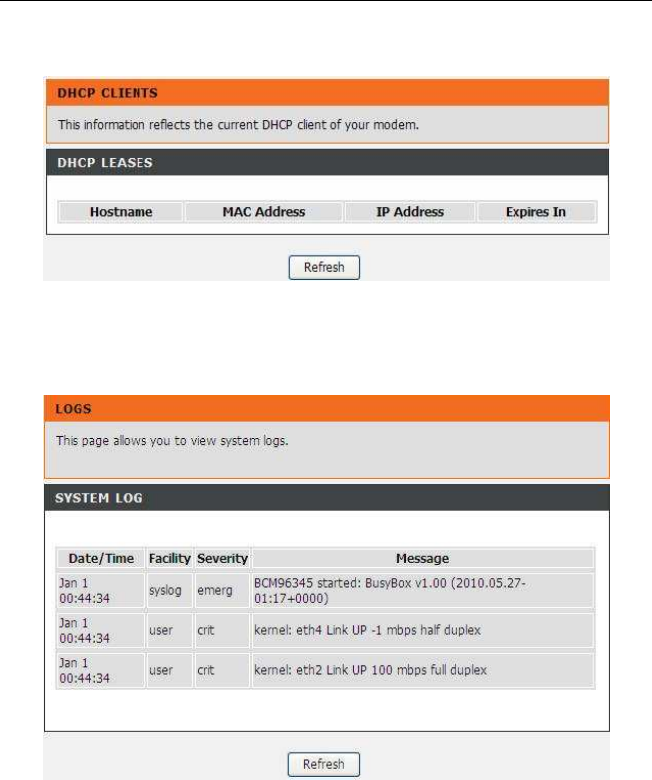
3.5.3 DHCP Clients
Choose STATUS > DHCP Clients. The page shown in the following page appears.
This page displays all client devices that obtain IP addresses from the device. You can
view the host name, IP address, MAC address and time expired(s).
3.5.4 Logs
Choose STATUS > Logs. The page shown in the following figure appears.
This page lists the system log. Click Refresh to refresh the system log shown in the table.
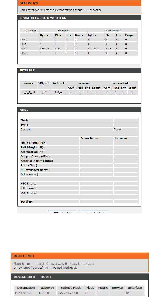
3.5.5 Statistics
Choose STATUS > Statistics. The page shown in the following
figure appears.
DSL-2750U/DSL-2750B User manual
This page displays the statistics of the network and data transfer. This information helps
technicians to identify if the device is functioning properly. The information does not affect
the function of the device.
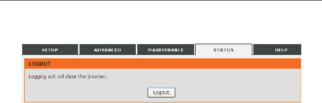
3.5.6 Route info
Choose STATUS > Route Info. The page shown in the following
figure appears.
The table shows a list of destination routes commonly accessed by the network.
DSL-2750U/DSL-2750B User manual
3.5.7 Logout
Choose STATUS > Logout. The page shown in the following figure appears. In this page,
you can log out of the configuration page.

DSL-2750U/DSL-2750B User manual
Federal Communication Commission Interference Statement
This equipment has been tested and found to comply with the limits
for a Class B digital device, pursuant to Part 15 of the FCC Rules.
These limits are designed to provide reasonable protection against
harmful interference in a residential installation. This equipment ge-
nerates, uses and can radiate radio frequency energy and, if not in-
stalled and used in accordance with the instructions, may cause
harmful interference to radio communications. However, there is no
guarantee that interference will not occur in a particular installation. If
this equipment does cause harmful interference to radio or
television reception, which can be determined by turning the equip-
ment off and on, the user is encouraged to try to correct the interfe-
rence by one of the following measures:
- Reorient or relocate the receiving antenna.
- Increase the separation between the equipment and receiver.
- Connect the equipment into an outlet on a circuit different from that
to which the receiver is connected.
- Consult the dealer or an experienced radio/TV technician for help.
FCC Caution: Any changes or modifications not expressly approved
by the party responsible for compliance could void the user's authori-
ty to operate this equipment.
This device complies with Part 15 of the FCC Rules. Operation is
subject to the following two conditions: (1) This device may not cause
harmful interference, and (2) this device must accept any interference
received, including interference that may cause undesired operation.
IMPORTANT NOTE:
FCC Radiation Exposure Statement:
This equipment complies with FCC radiation exposure limits set forth
for an uncontrolled environment. This equipment should be installed
and operated with minimum distance 20cm between the radiator &
your body.
This transmitter must not be co-located or operating in conjunction
with any other antenna or transmitter.
Note: The country selection mode is for non-US models only and is
not available to the US model(s).
Part 68 Statement
This equipment complies with Part 68 of the FCC rules and the require-
ments adopted by the ACTA. On the bottom of this equipment is a label
that contains, among other information, a product identifier in the format
US: 3P7DL01BSL2750UT1,.If requested, this number must be provided
to the telephone company.
The REN is used to determine the number of devices that may be con-
nected to a telephone line. Excessive RENs on a telephone line may
result in the devices not ringing in response to an incoming call. In most
but not all areas, the sum of RENs should not exceed five (5.0). To be
certain of the number of devices that may be connected to a line, as de-
termined by the total RENs, contact the local telephone company. For
products approved after July 23, 2001, the REN for this product is part of
the product identifier that has the format US: 3P7DL01BSL2750UT1.
The digits represented by 01 are the REN without a decimal point (e.g.,
03 is a REN of 0.3). For earlier products, the REN is separately shown
on the label.
If your equipment causes harm to the telephone network, the telephone
company may discontinue your service temporarily. If possible, they will
notify you in advance. But if advance notice is not practical, you will be
notified as soon as possible. You will be informed of your right to file a

DSL-2750U/DSL-2750B User manual
complaint with the FCC. Your telephone company may make changes in
its facilities, equipment, operations or procedures that could affect the
proper functioning of your equipment. If they do, you will be notified in
advance to give you an opportunity to maintain uninterrupted telephone
service.
If you experience trouble with this telephone equipment, please contact
the following address and phone number for information on obtaining
service or repairs.
The telephone company may ask that you disconnect this equipment
from the network until the problem has been corrected or until you are
sure that the equipment is not malfunctioning.
This equipment may not be used on coin service provided by the tele-
phone company. Connection to party lines is subject to state tariffs.
Company: D-Link Corporation
Address: 17595 Mt. Herrmann, Fountain Valley, CA 92708
U.S.A
Tel no.:
1.877.943.5465