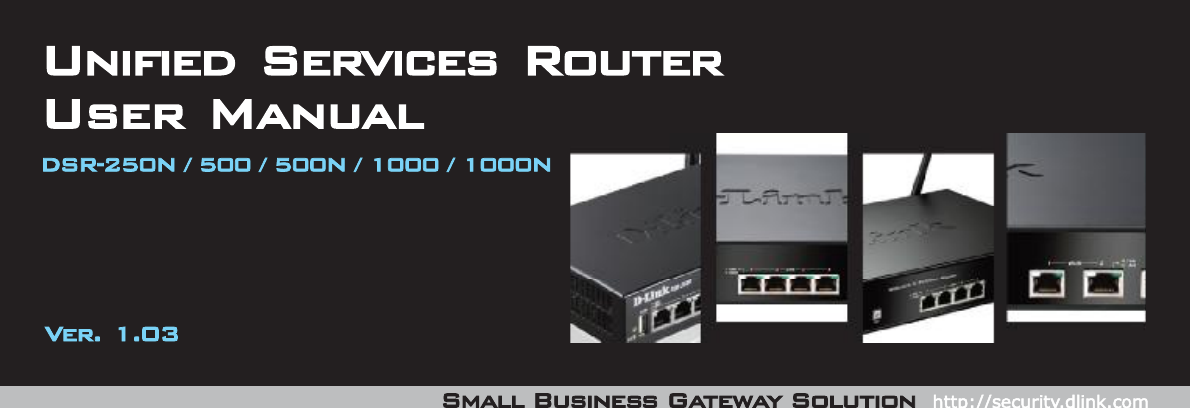
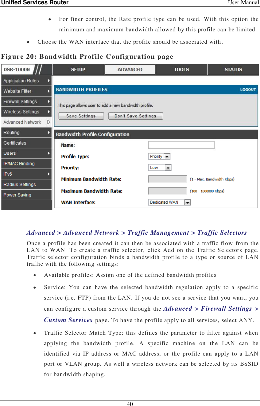
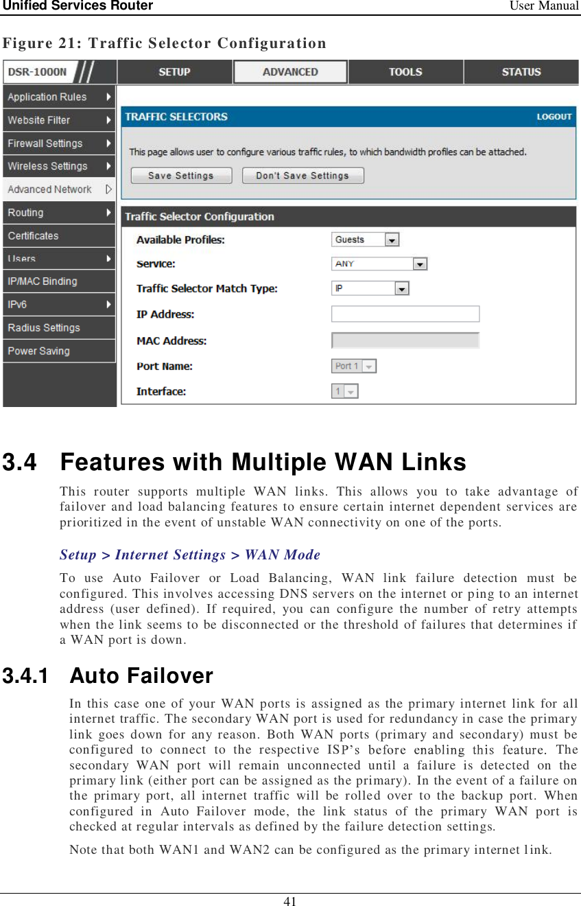
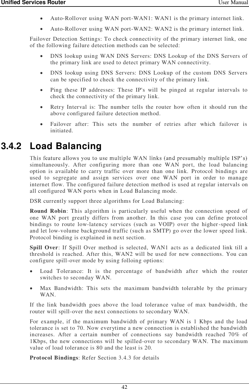
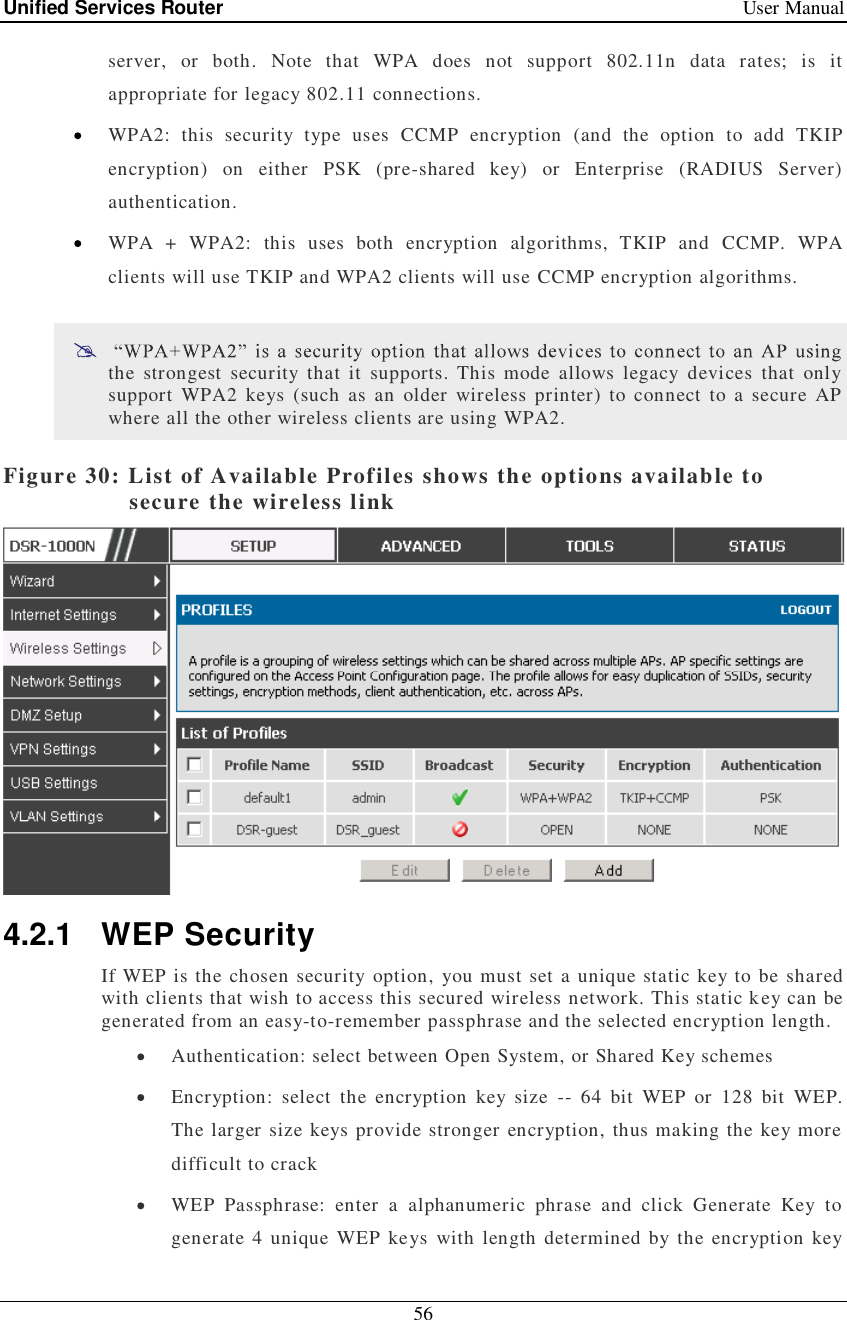
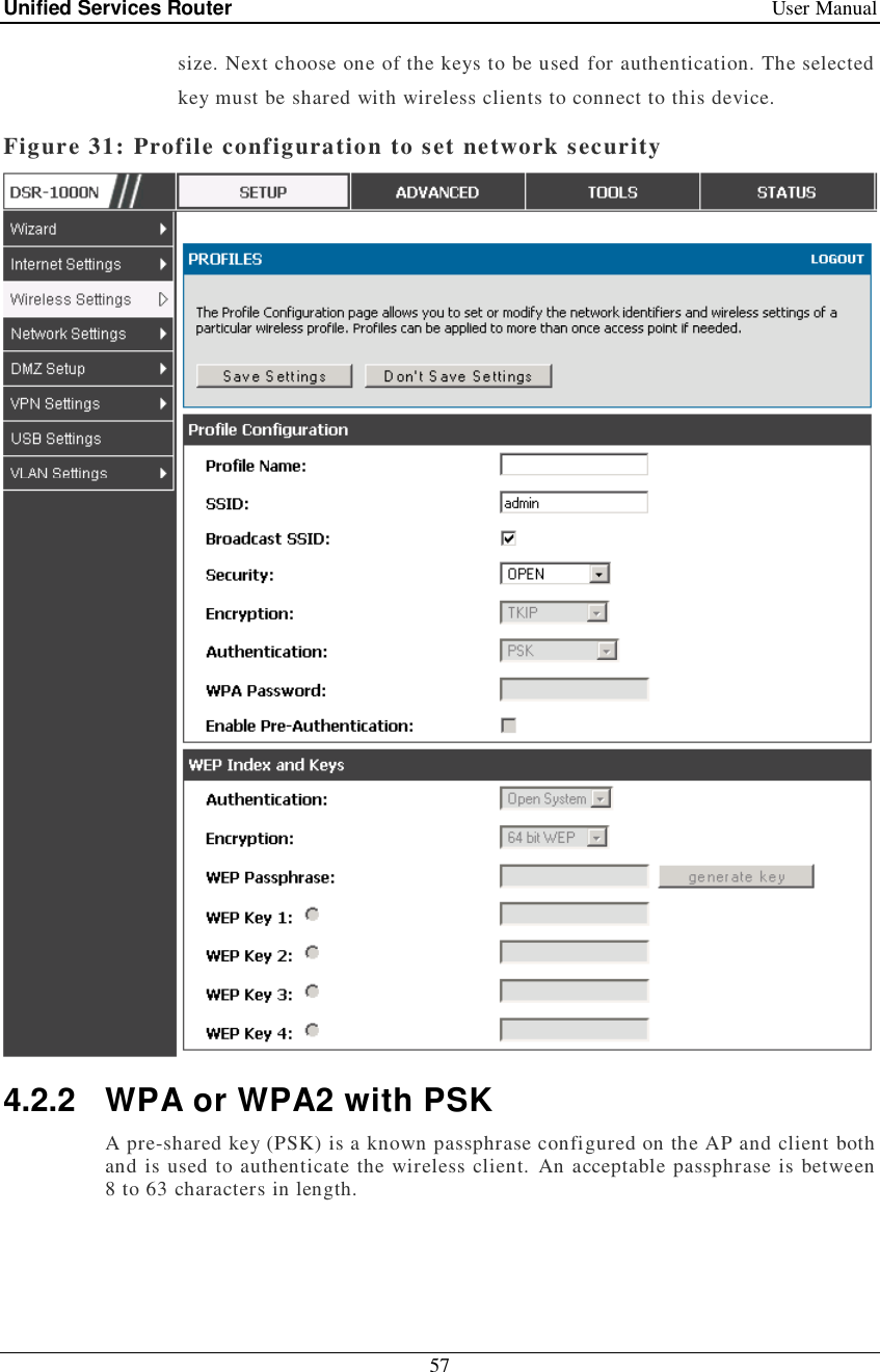
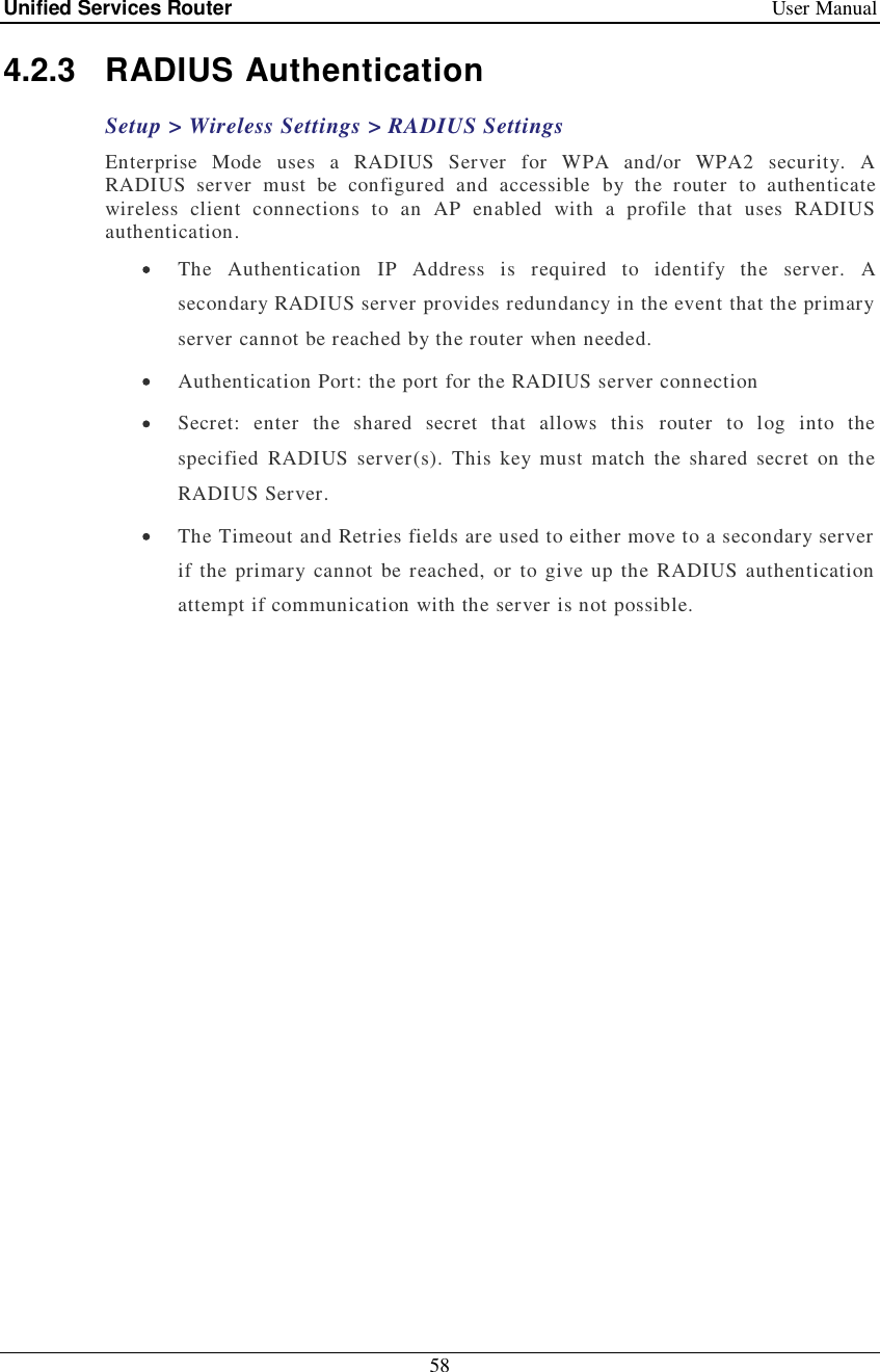
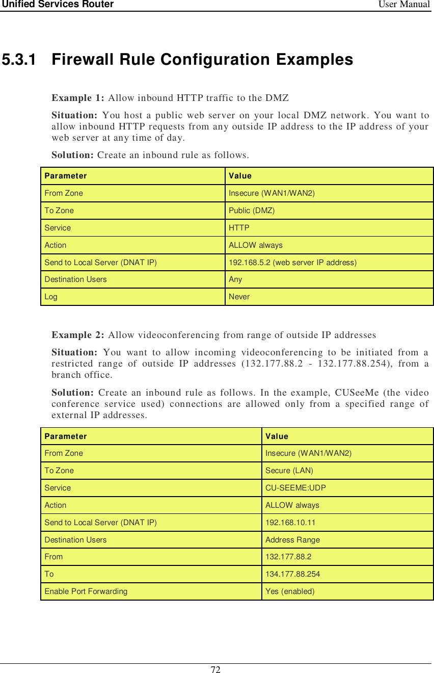
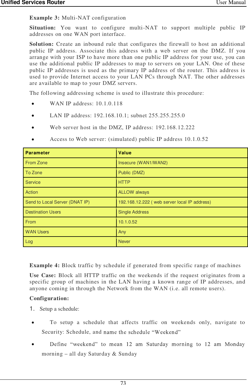
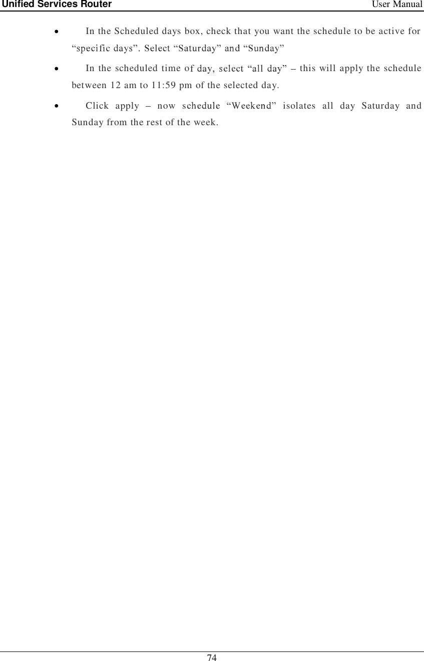
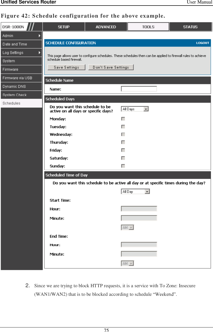
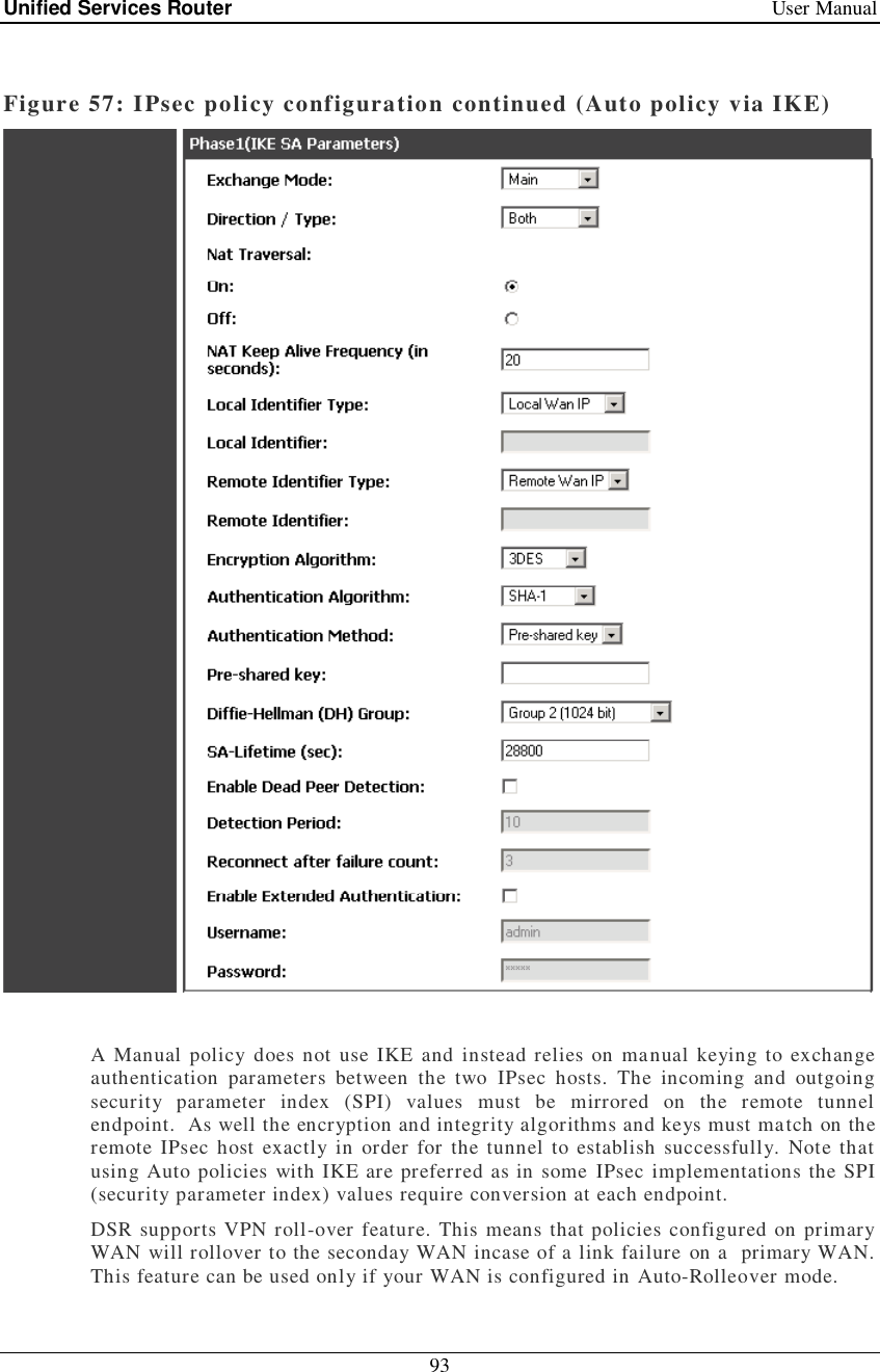
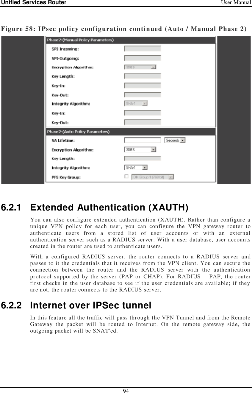
D Link SR250NA1 Wireless N Service Router User Manual DSR 250N UserManual
D Link Corporation Wireless N Service Router DSR 250N UserManual
UserManual.wiki
>
D Link
>
SR250NA1 User Manual
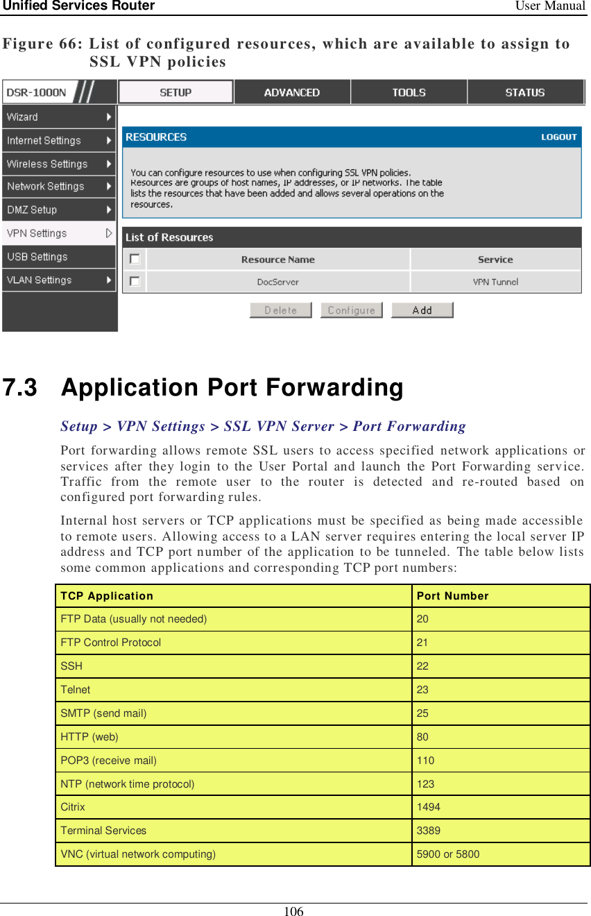
>
User manual 1 of 2
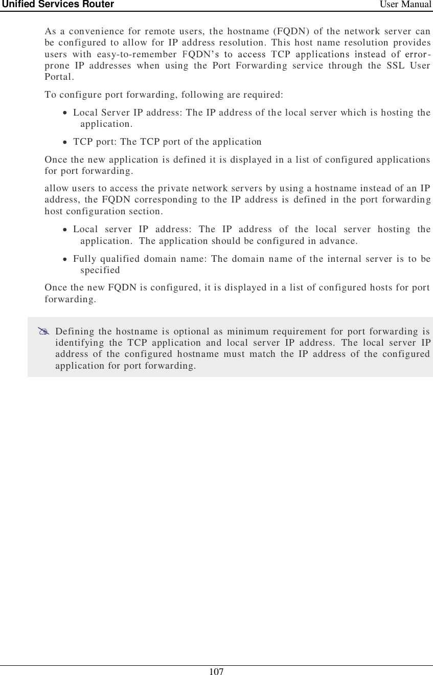
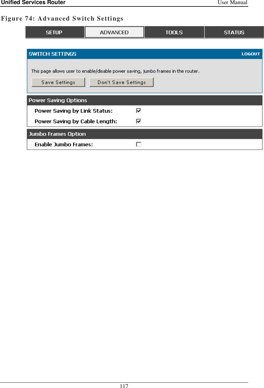
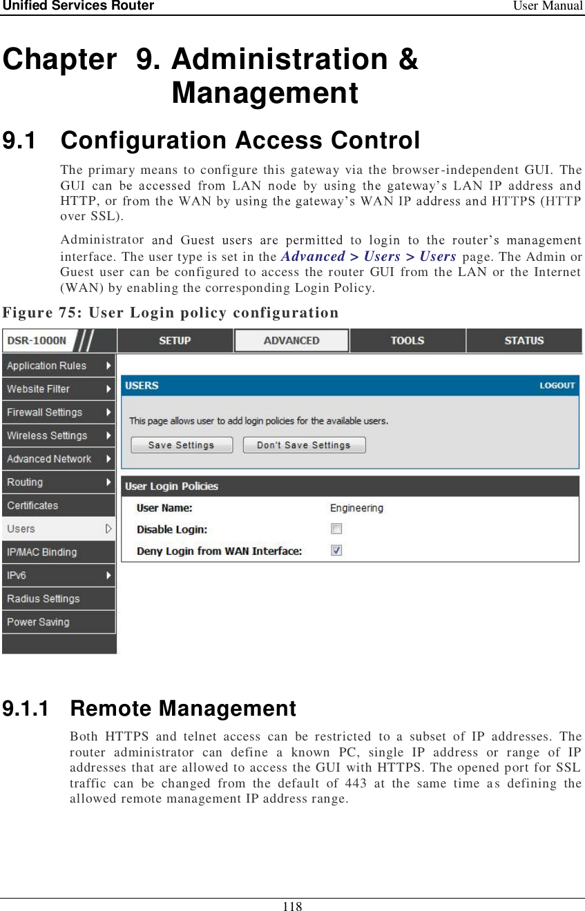
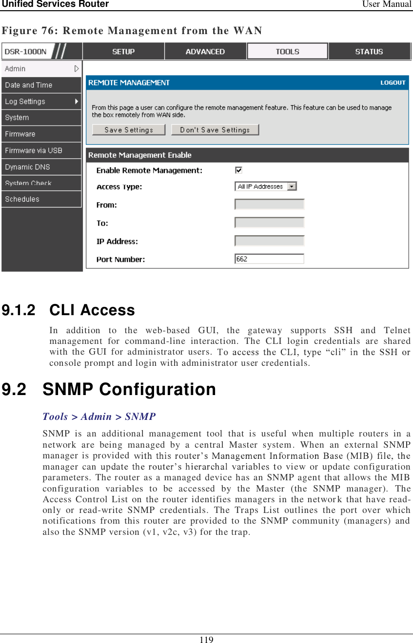
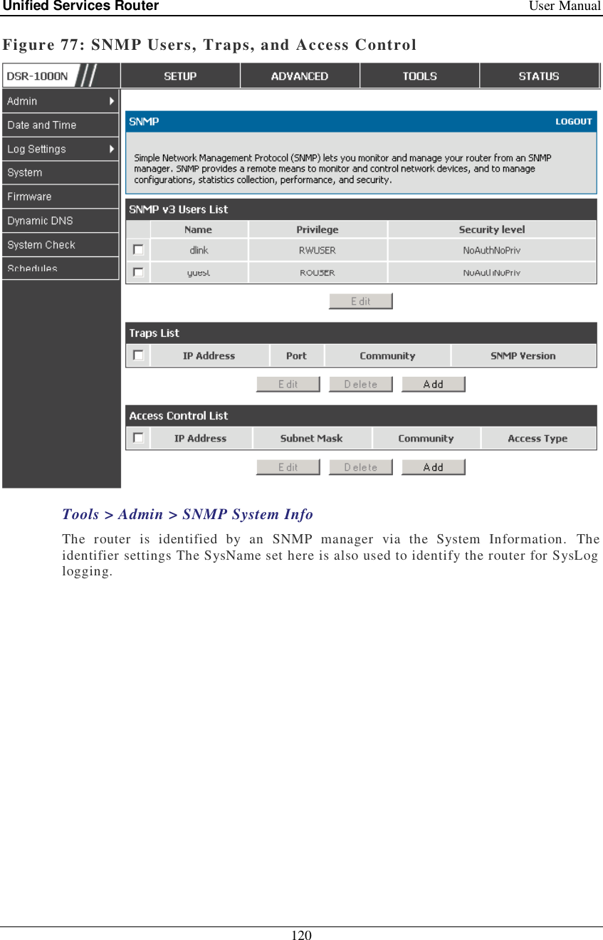
Contents
1.
User manual 1 of 2
2.
User manual 2 of 2
User manual 1 of 2
Navigation menu
Upload a User Manual
Namespaces
Wiki Guide
HTML
PDF
Info
Views
User Manual
Discussion / Help
Navigation