D Link SR500ACA1 AC800 Selectable Dual Band VPN Business Router User Manual
D Link Corporation AC800 Selectable Dual Band VPN Business Router
UserManual.wiki
>
D Link
>
SR500ACA1 User Manual
User manual
Navigation menu
Upload a User Manual
Namespaces
Wiki Guide
HTML
PDF
Info
Views
User Manual
Discussion / Help
Navigation
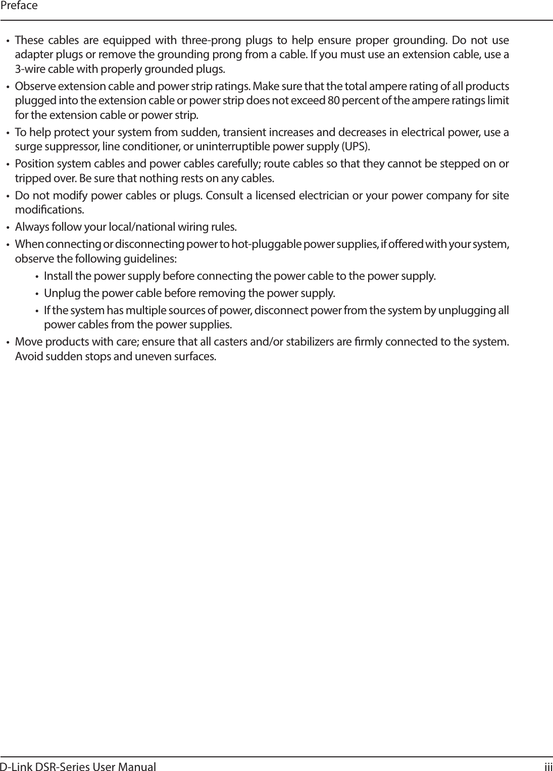
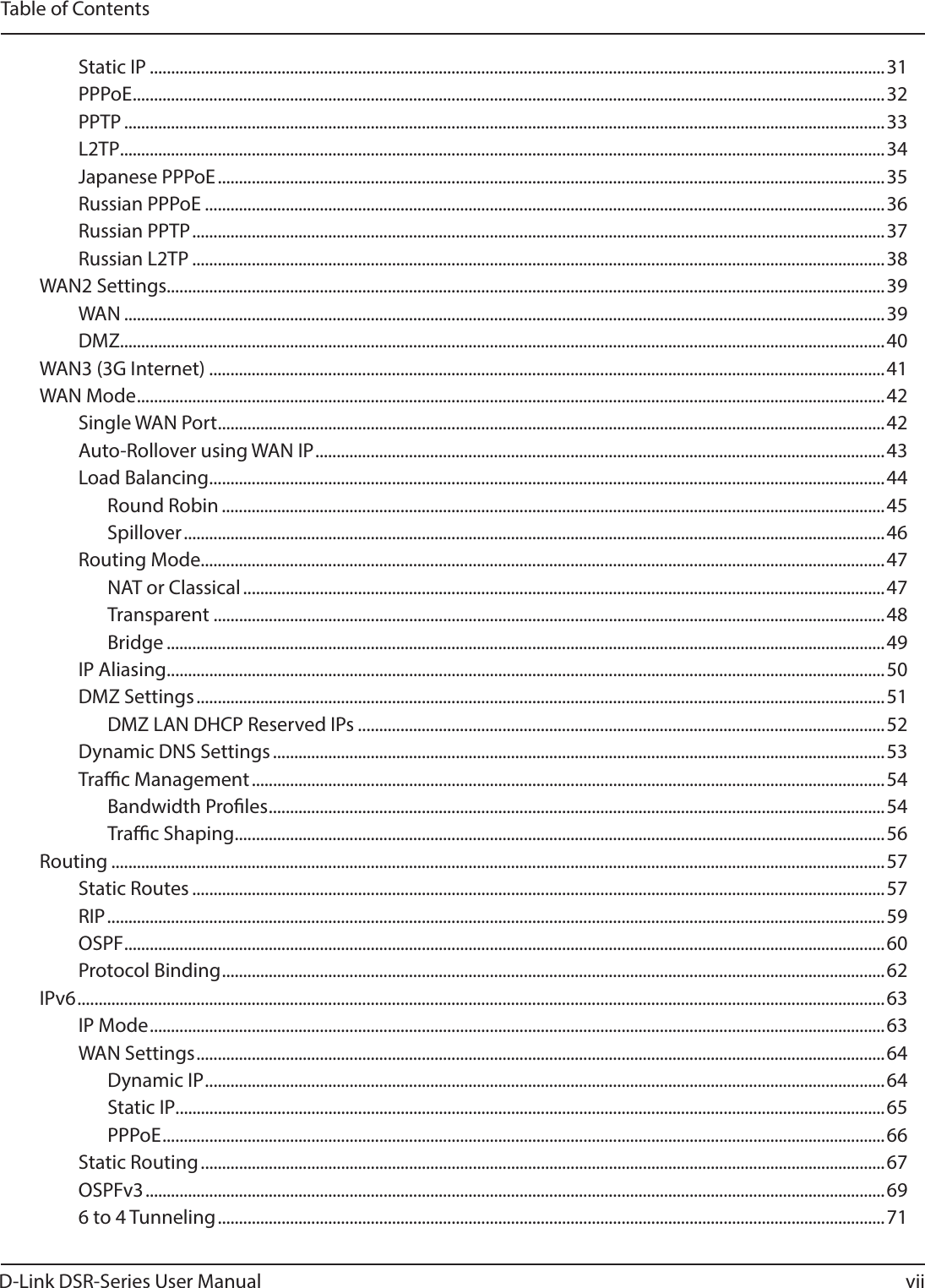
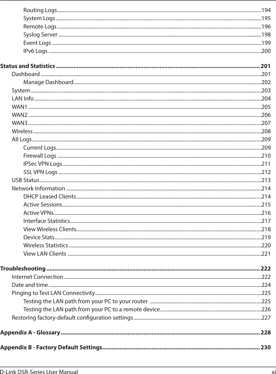
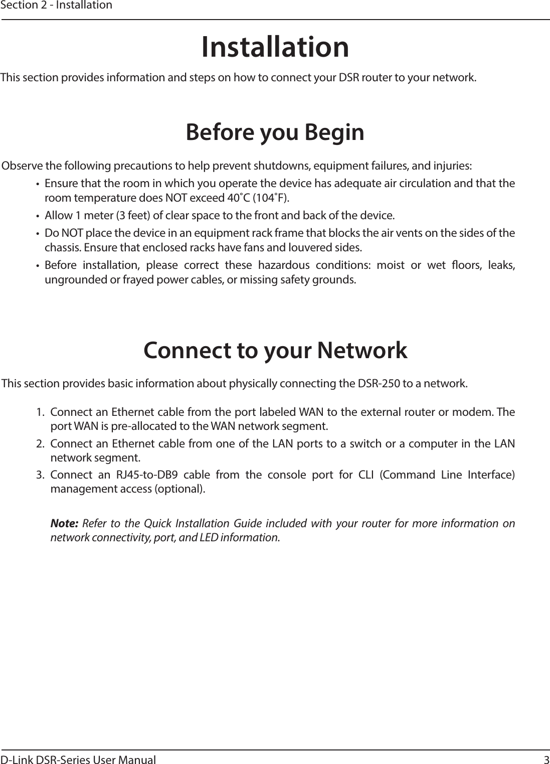
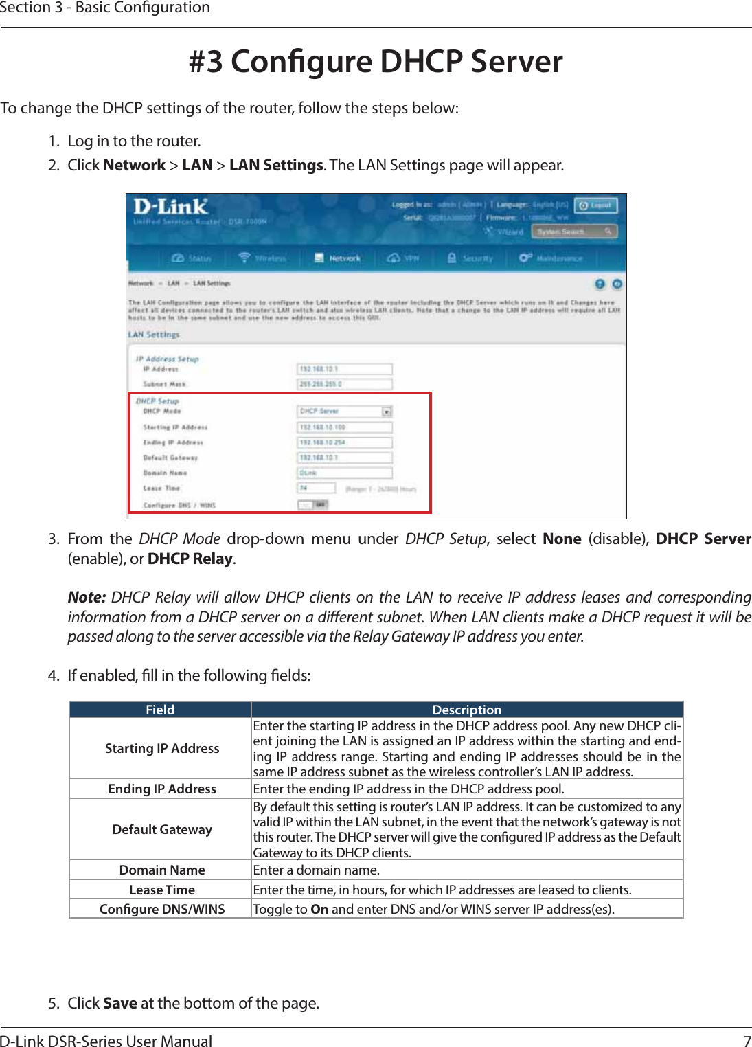
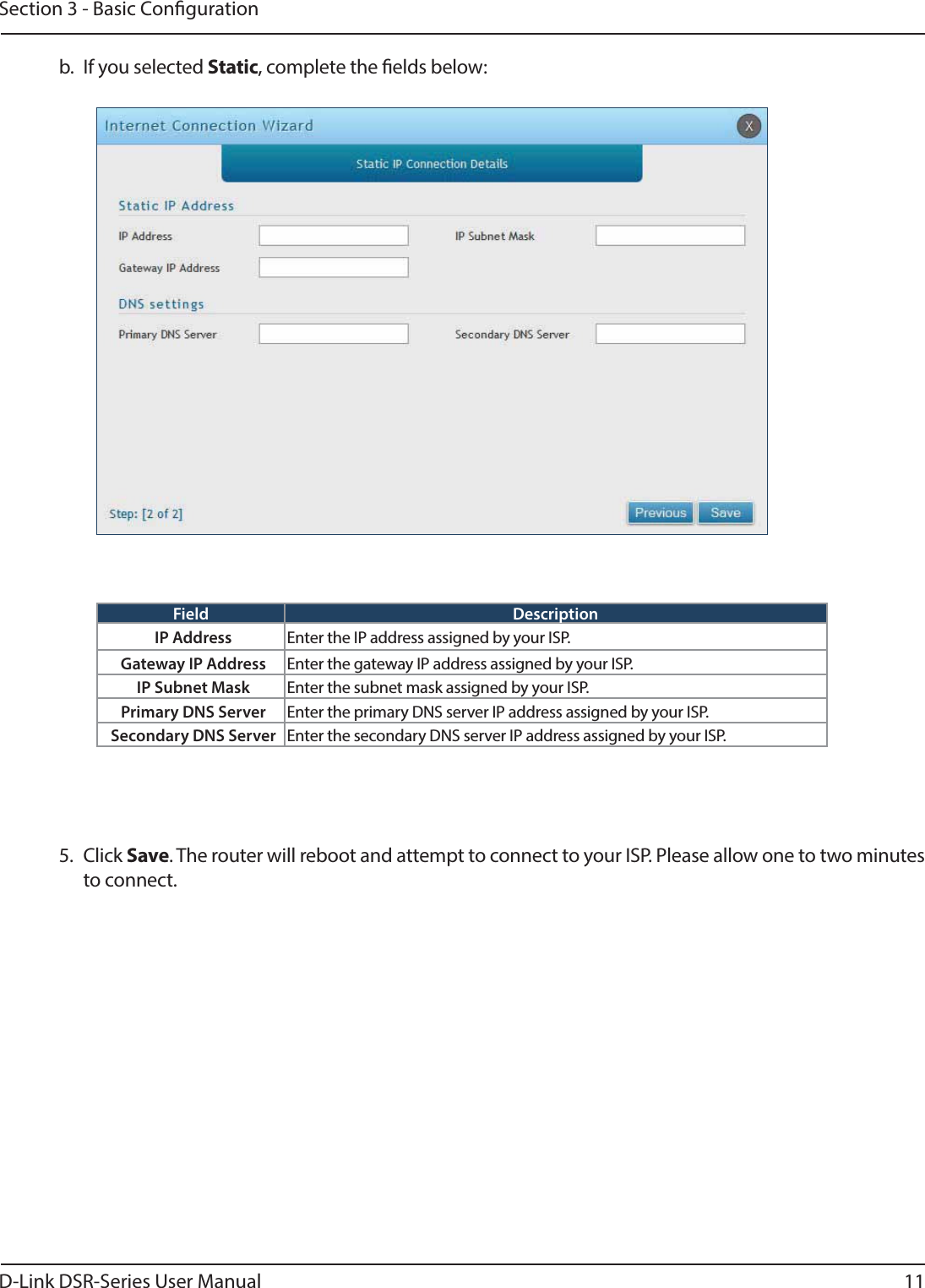
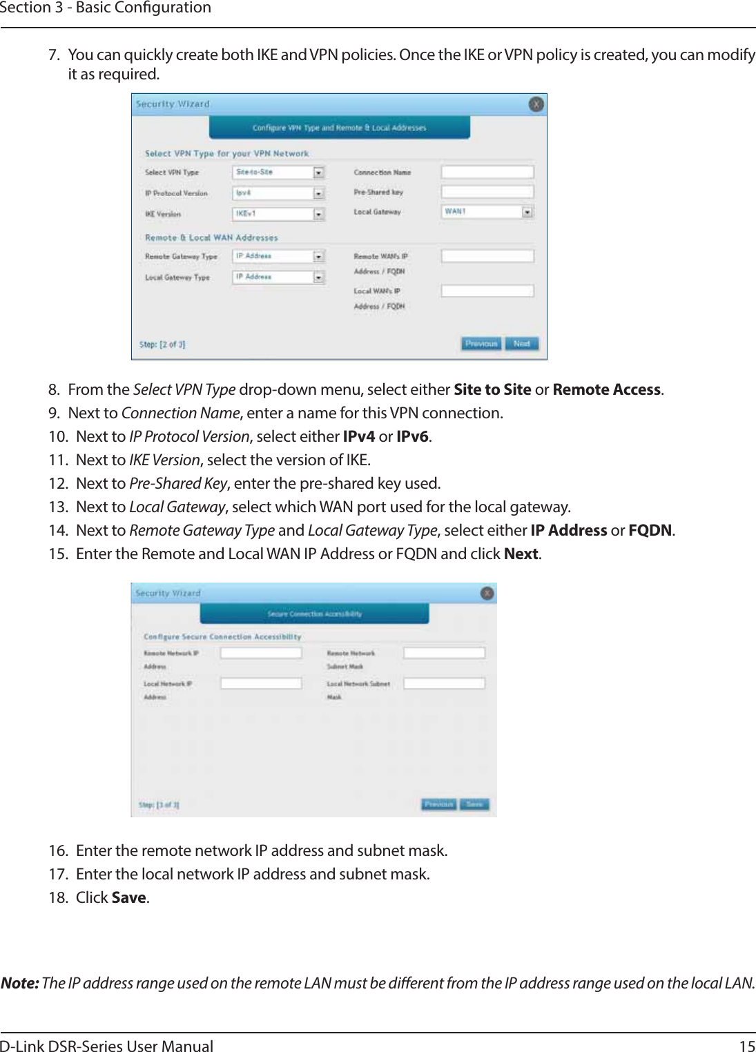
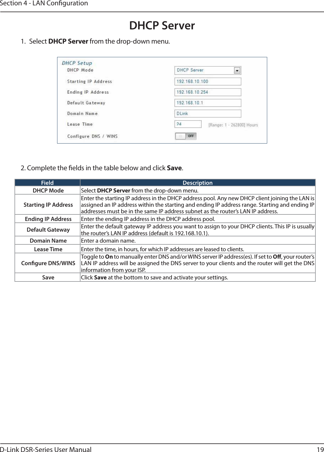
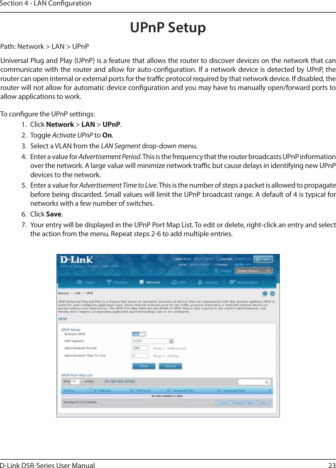
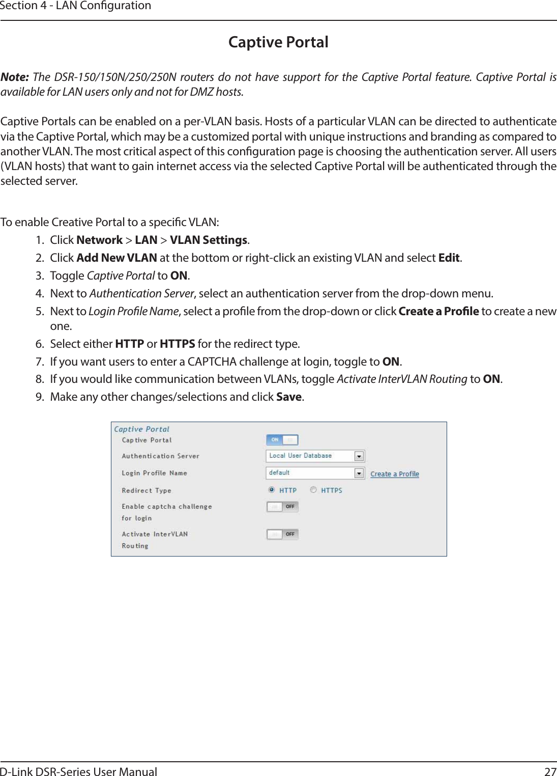
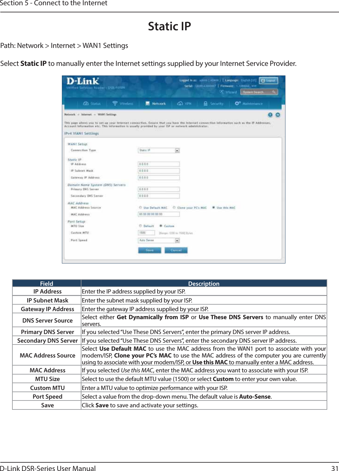
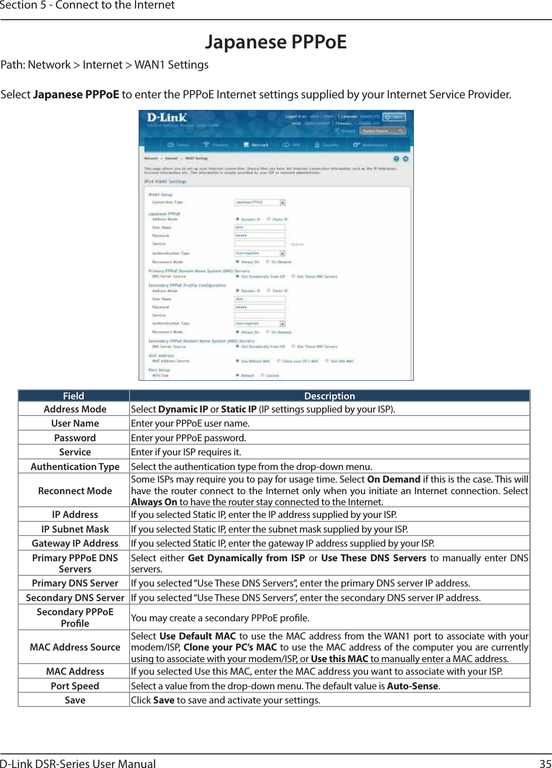
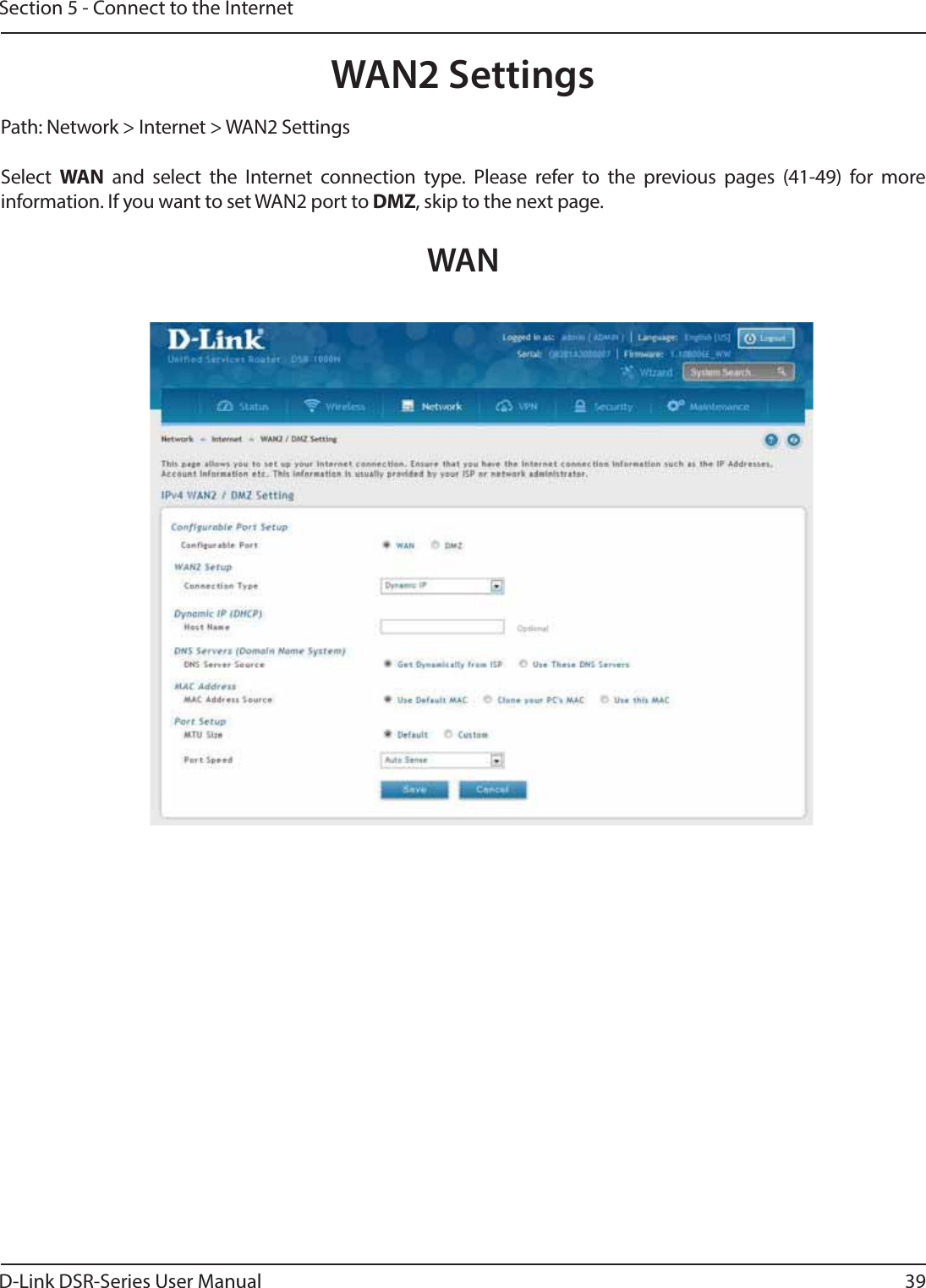
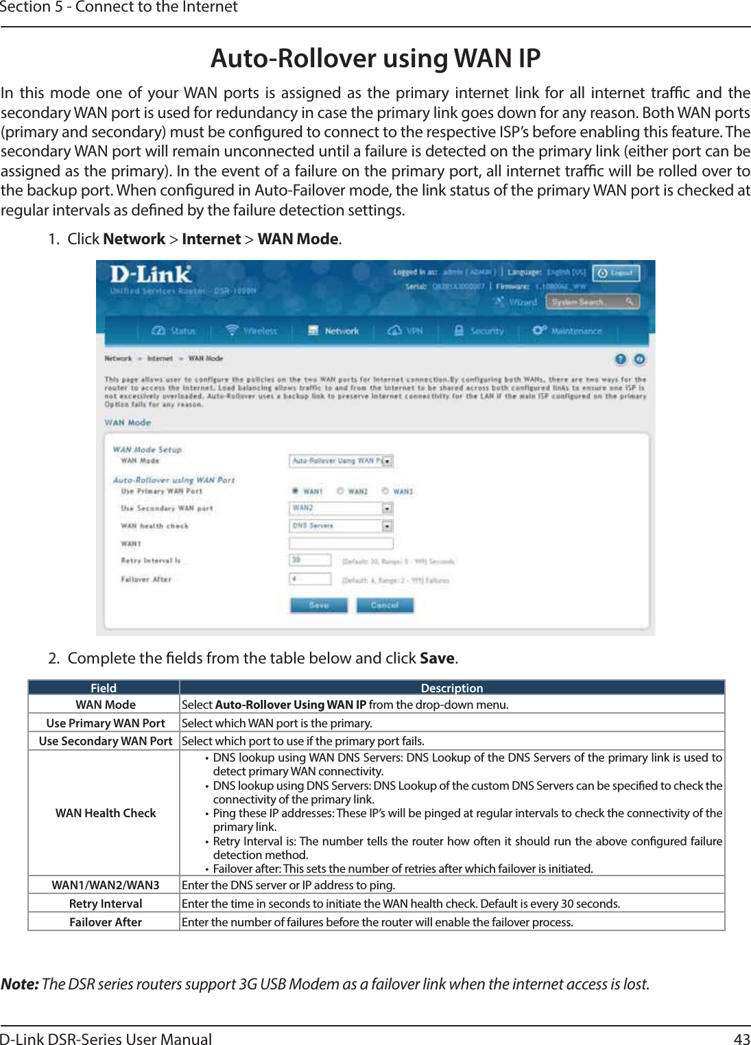
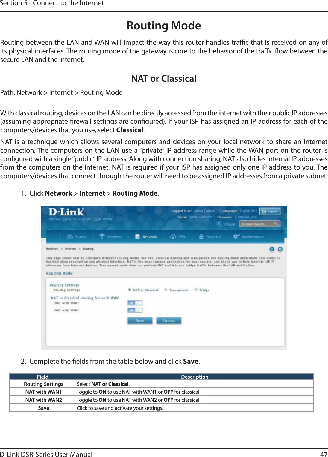
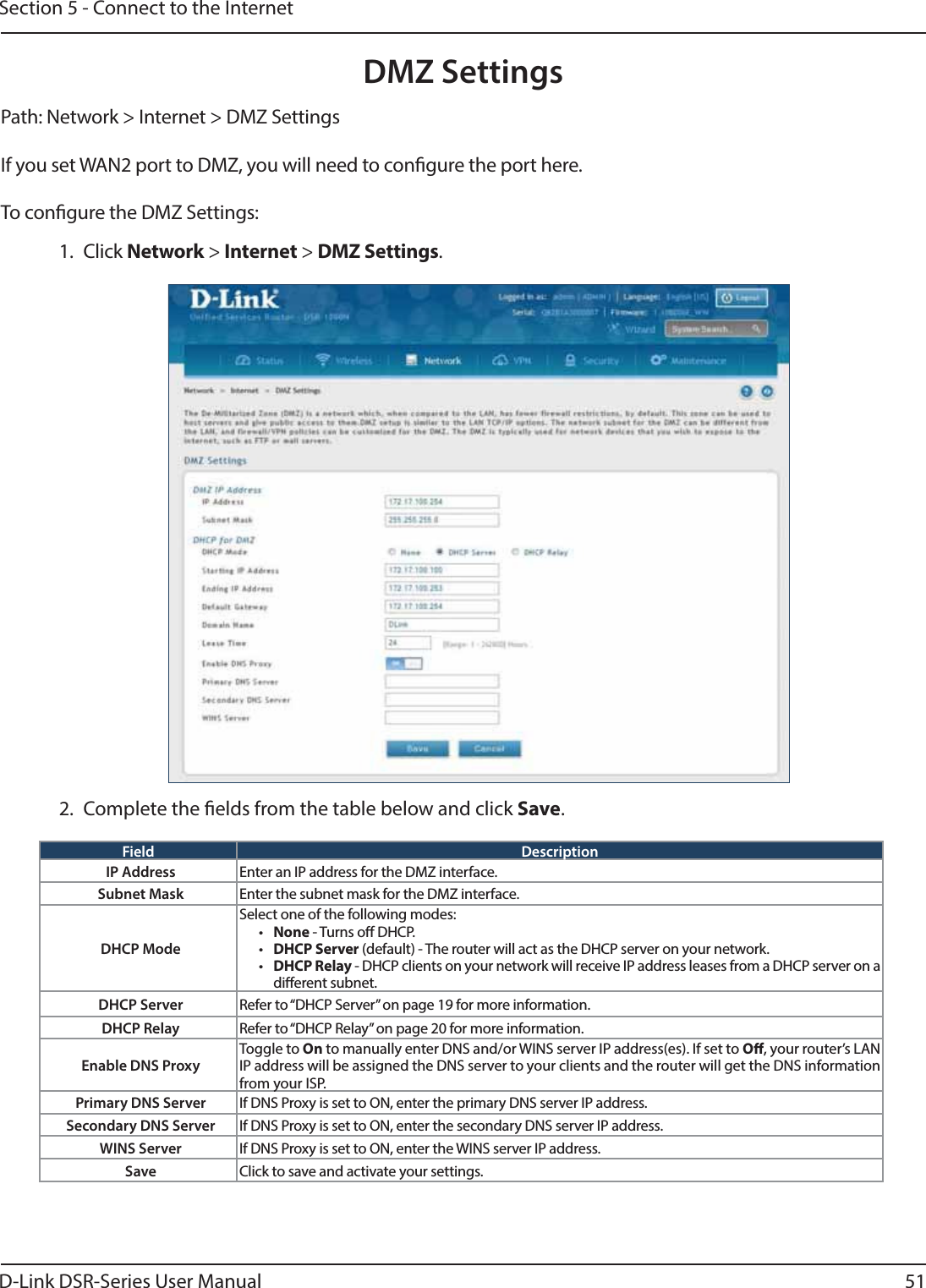
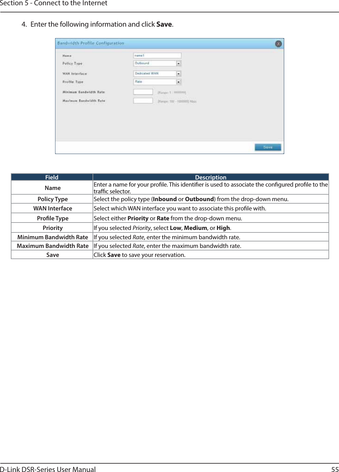
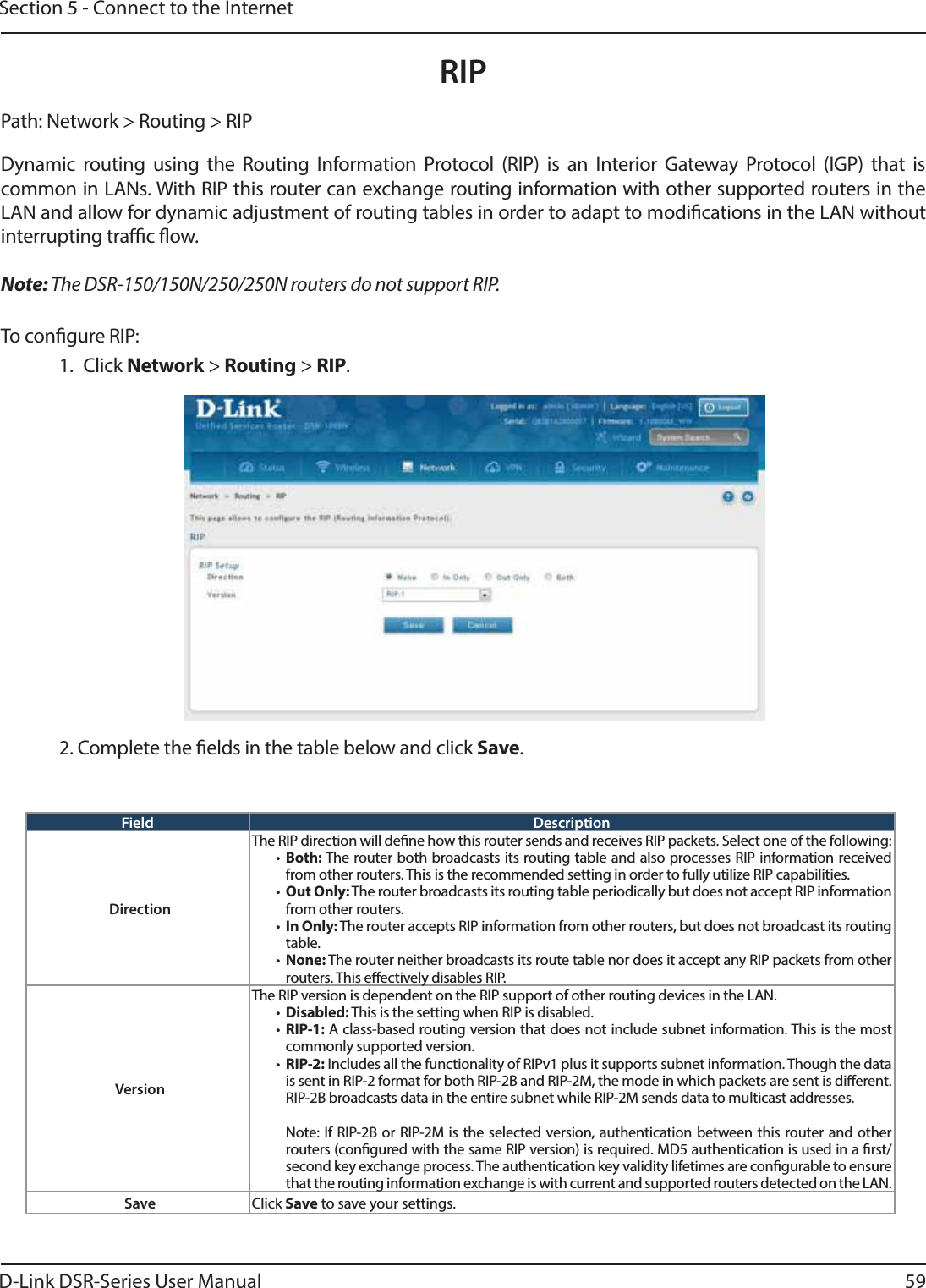
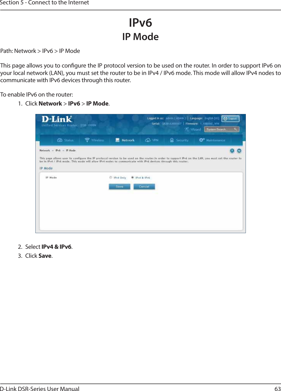
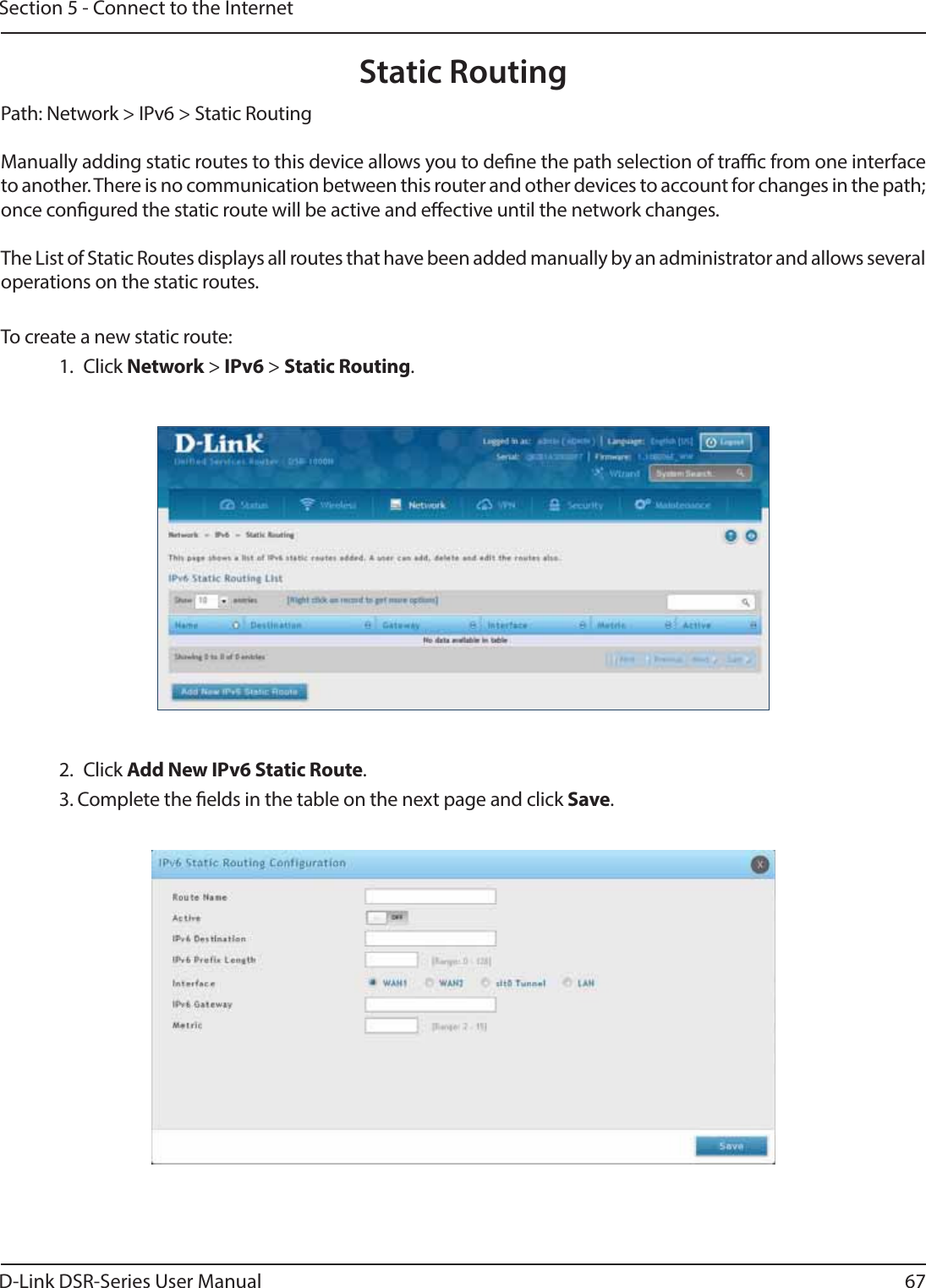
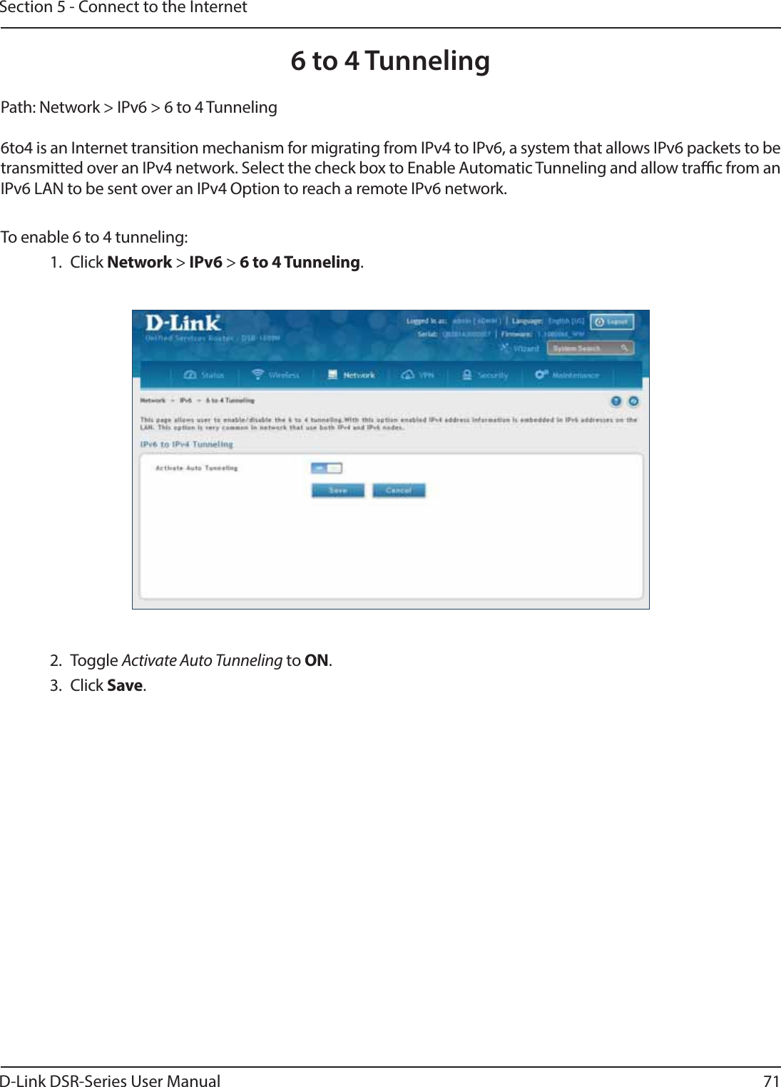
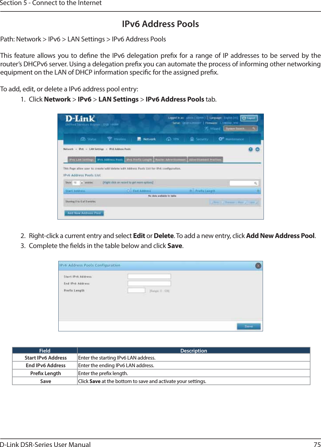
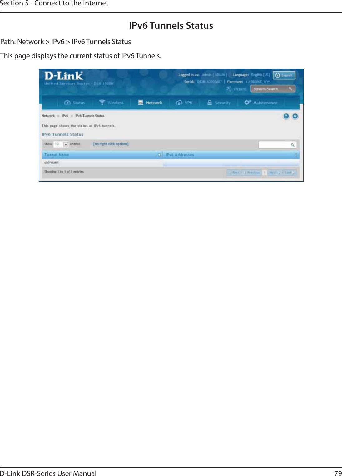
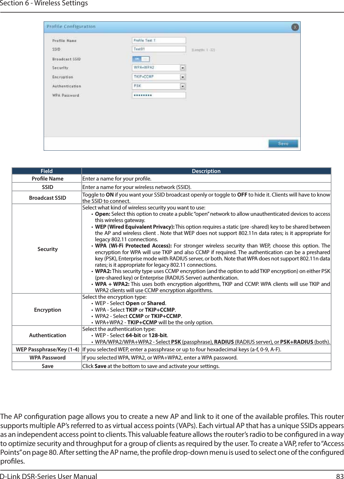

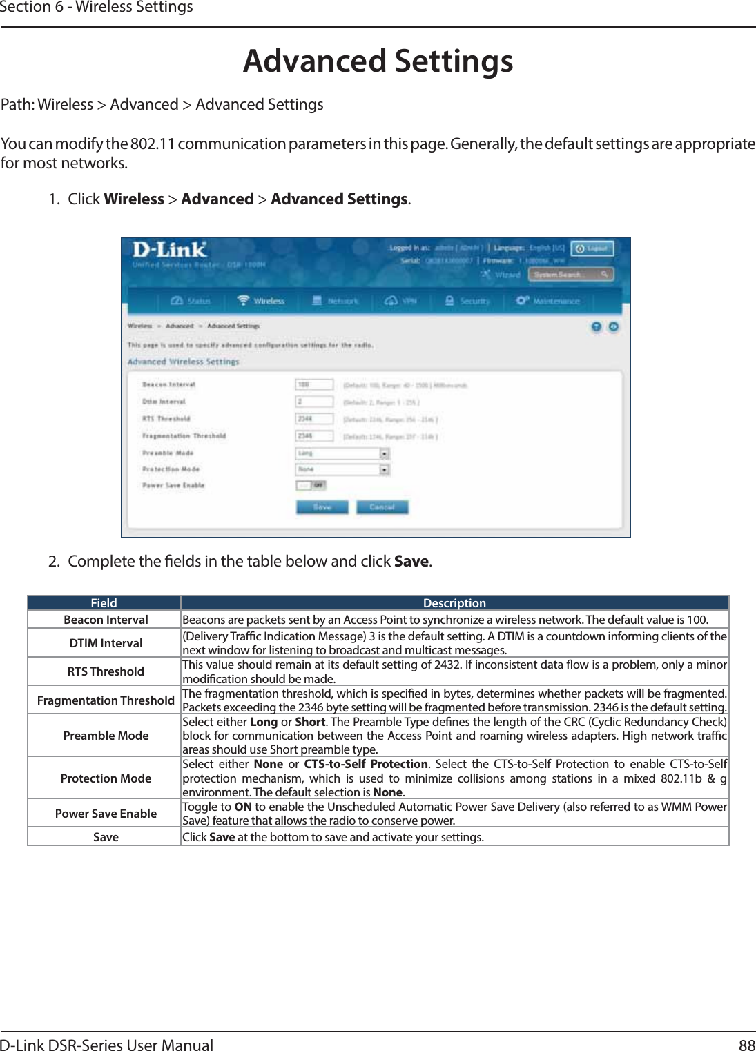
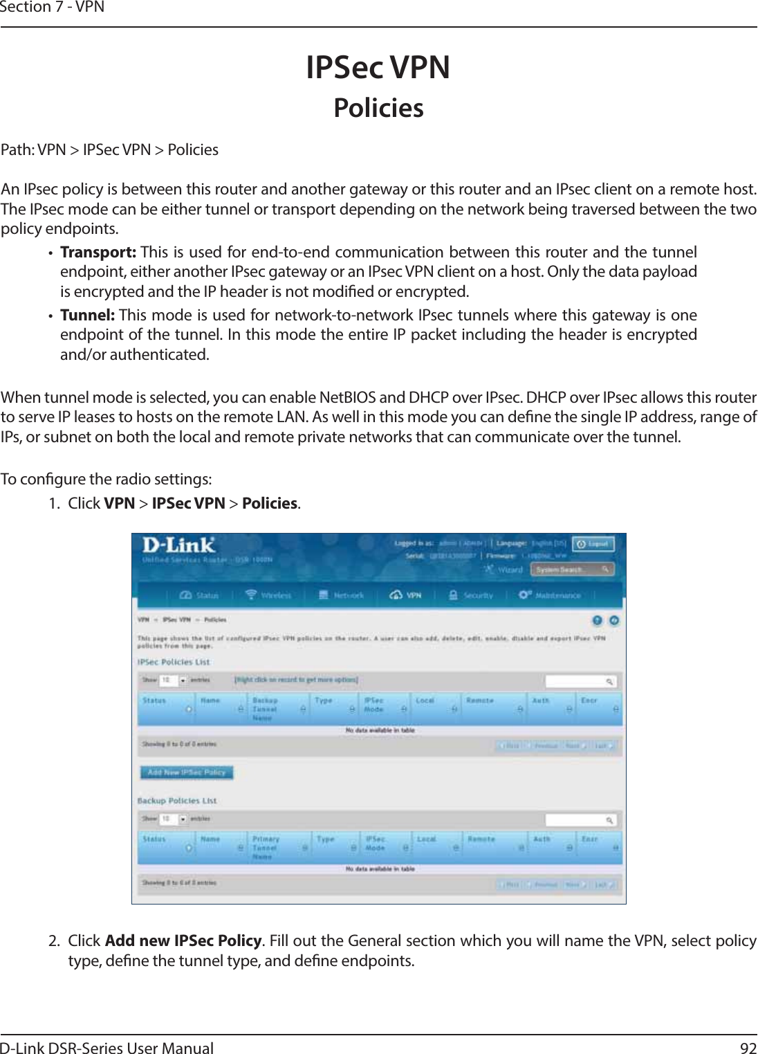
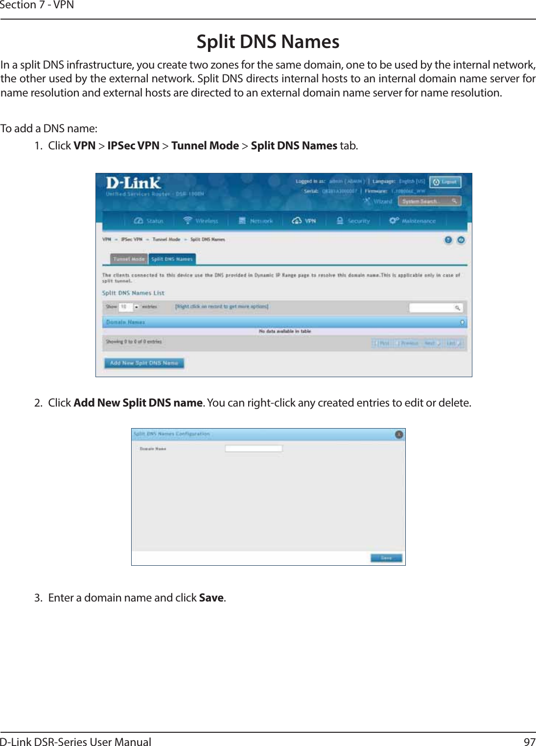
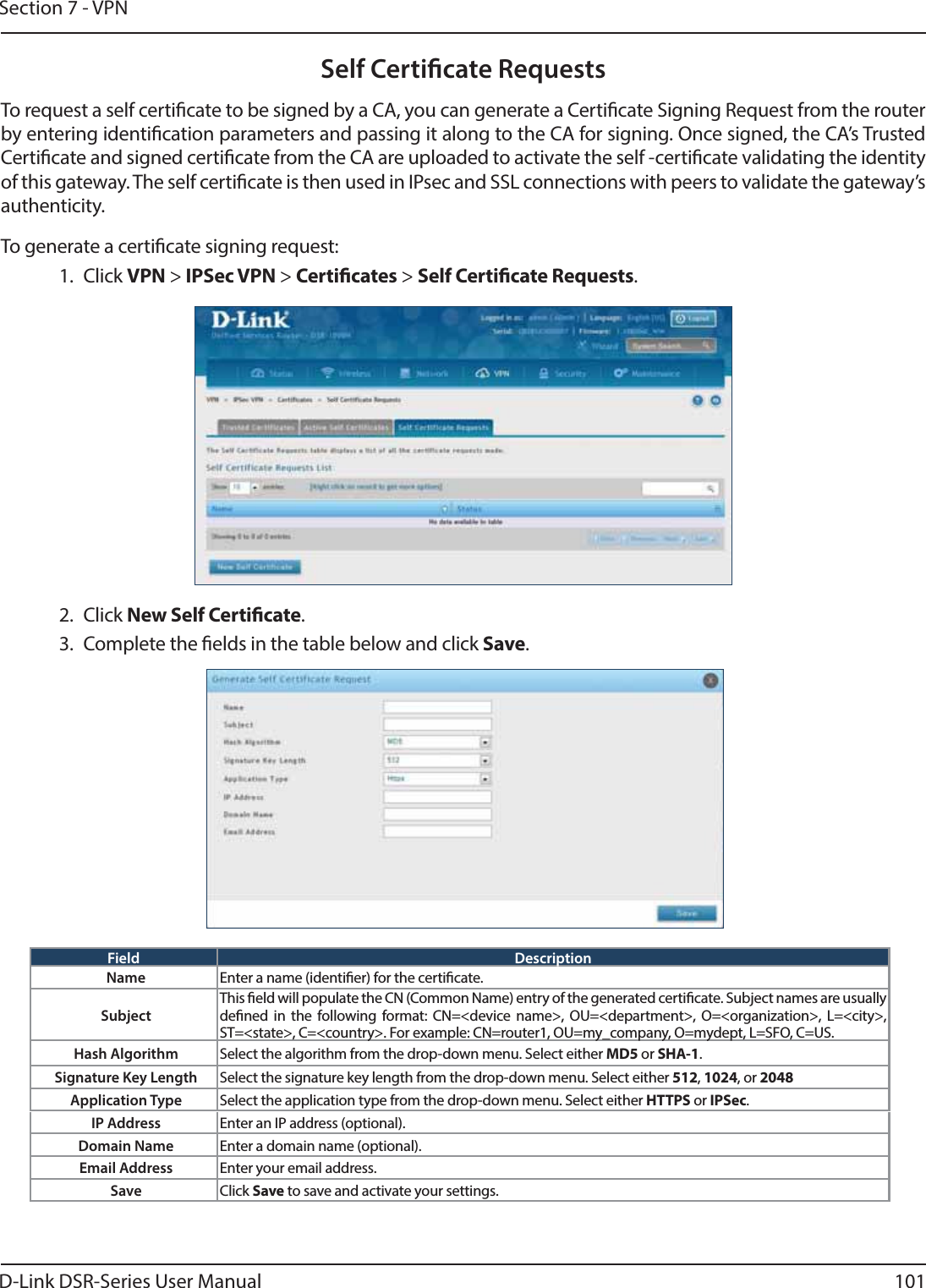
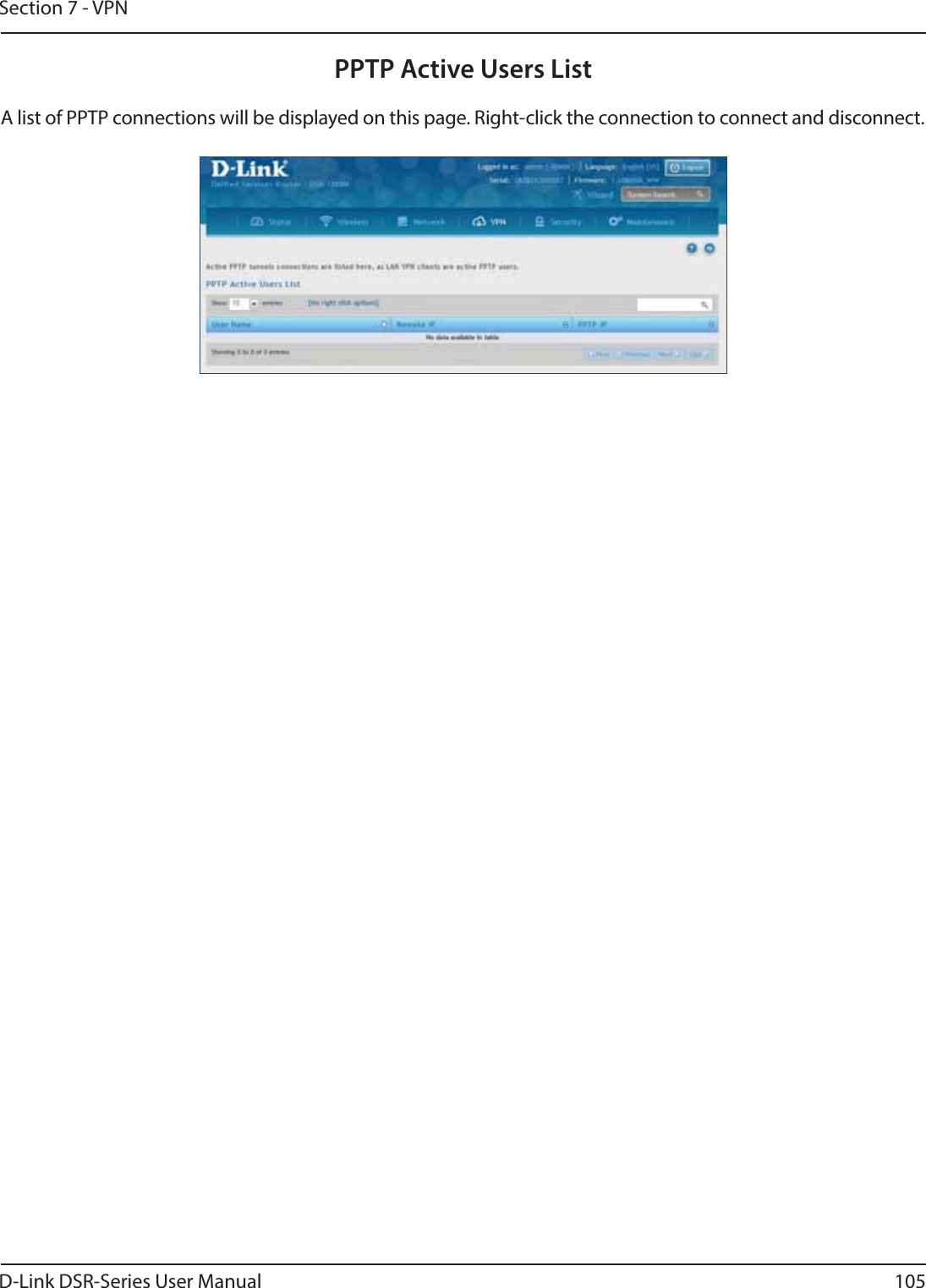
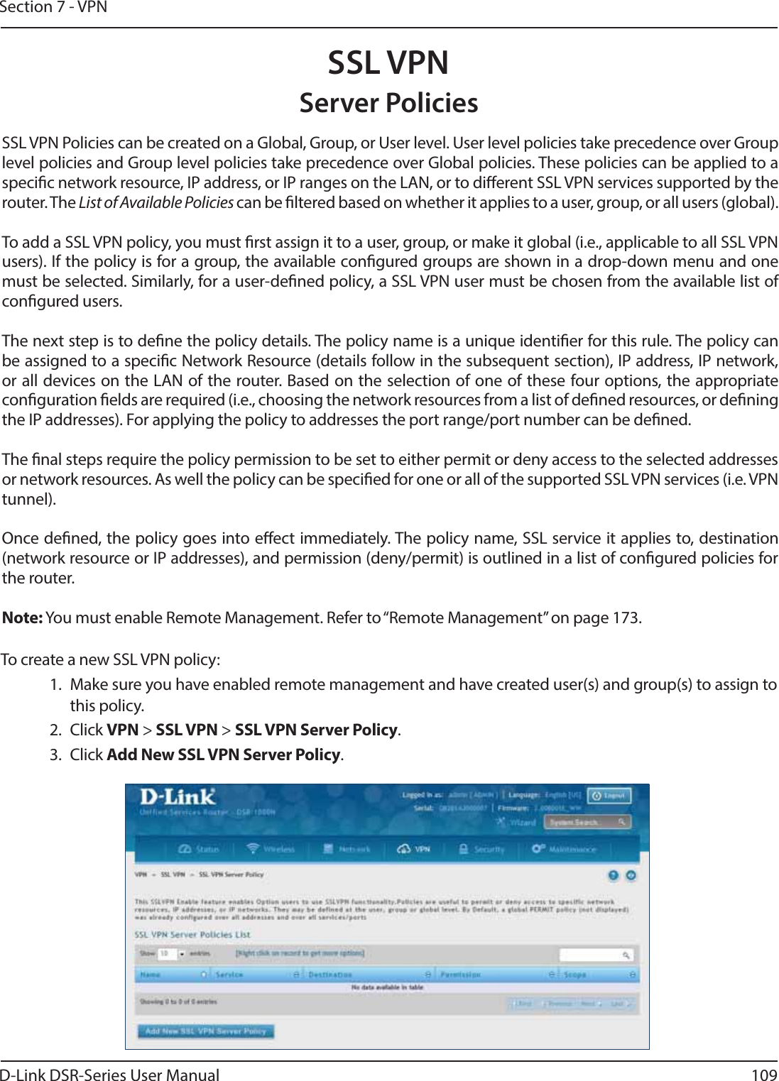
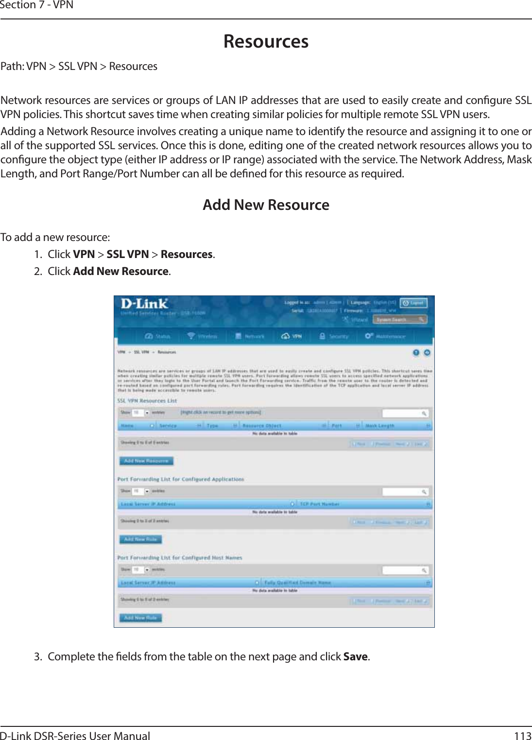
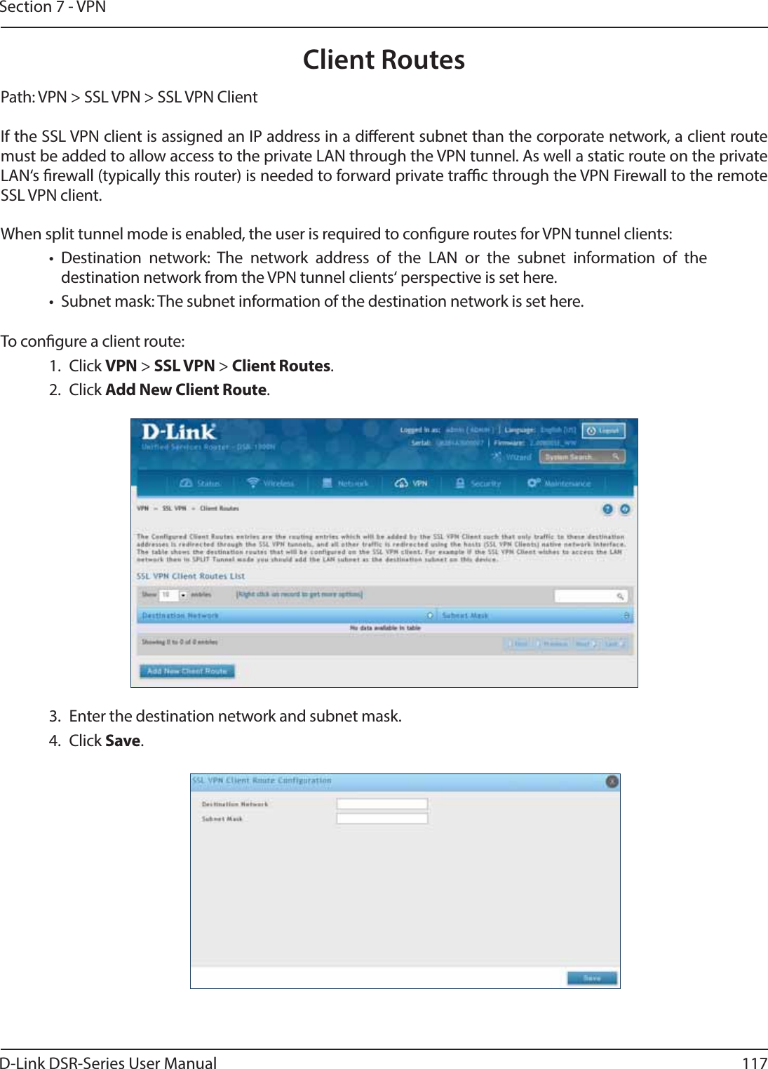
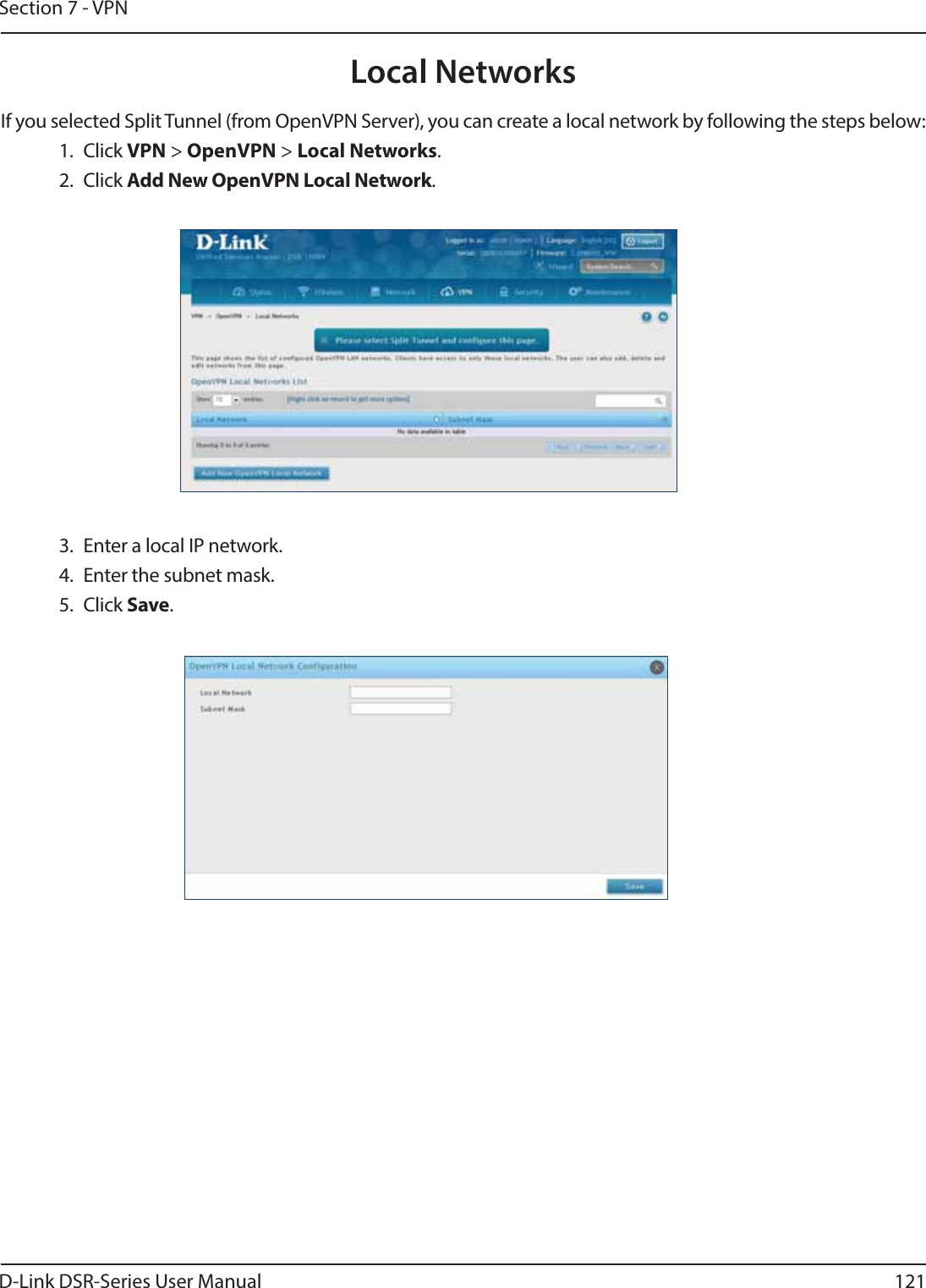
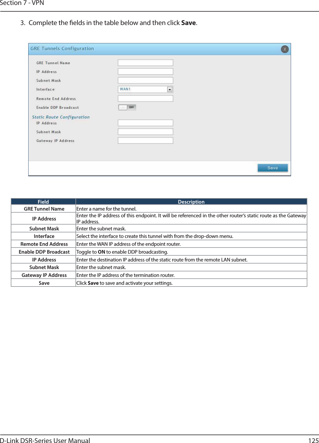
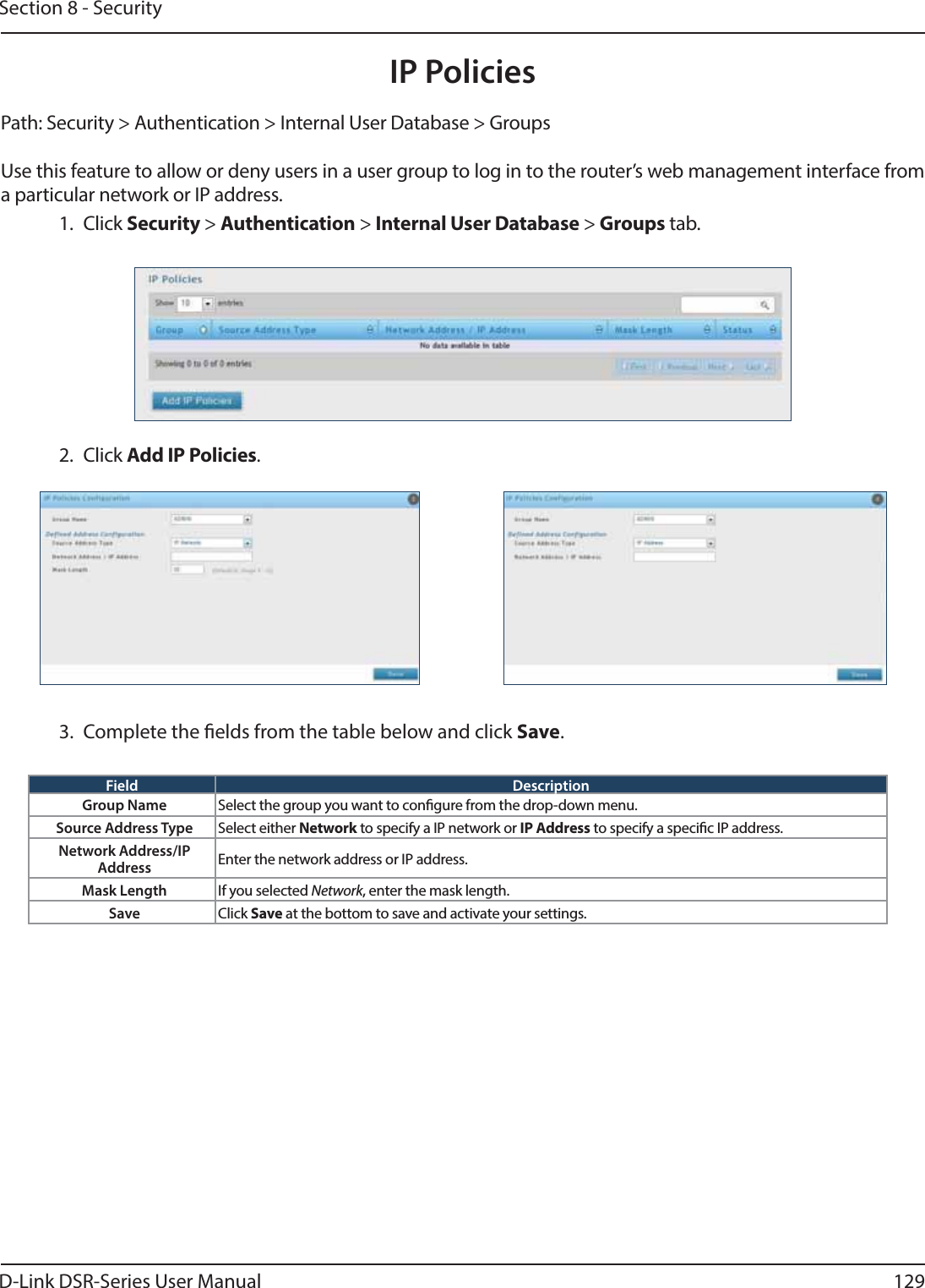
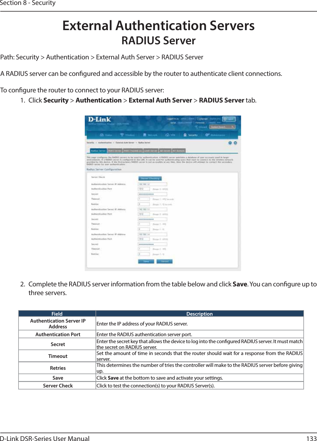
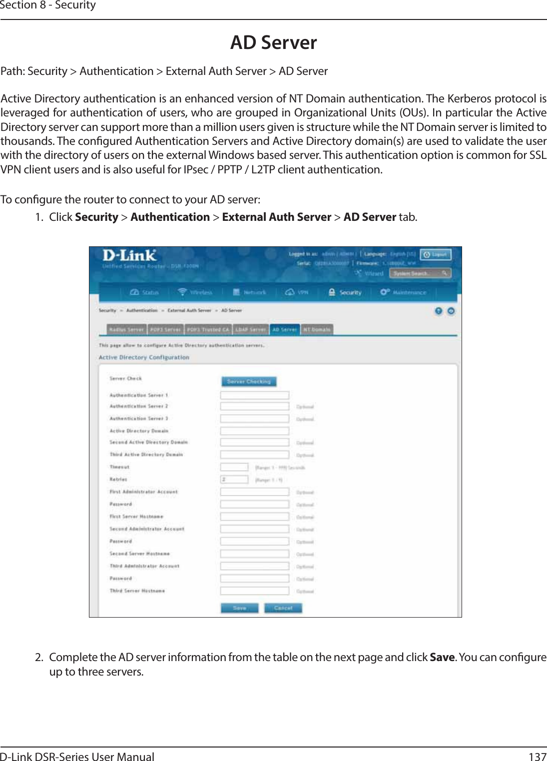
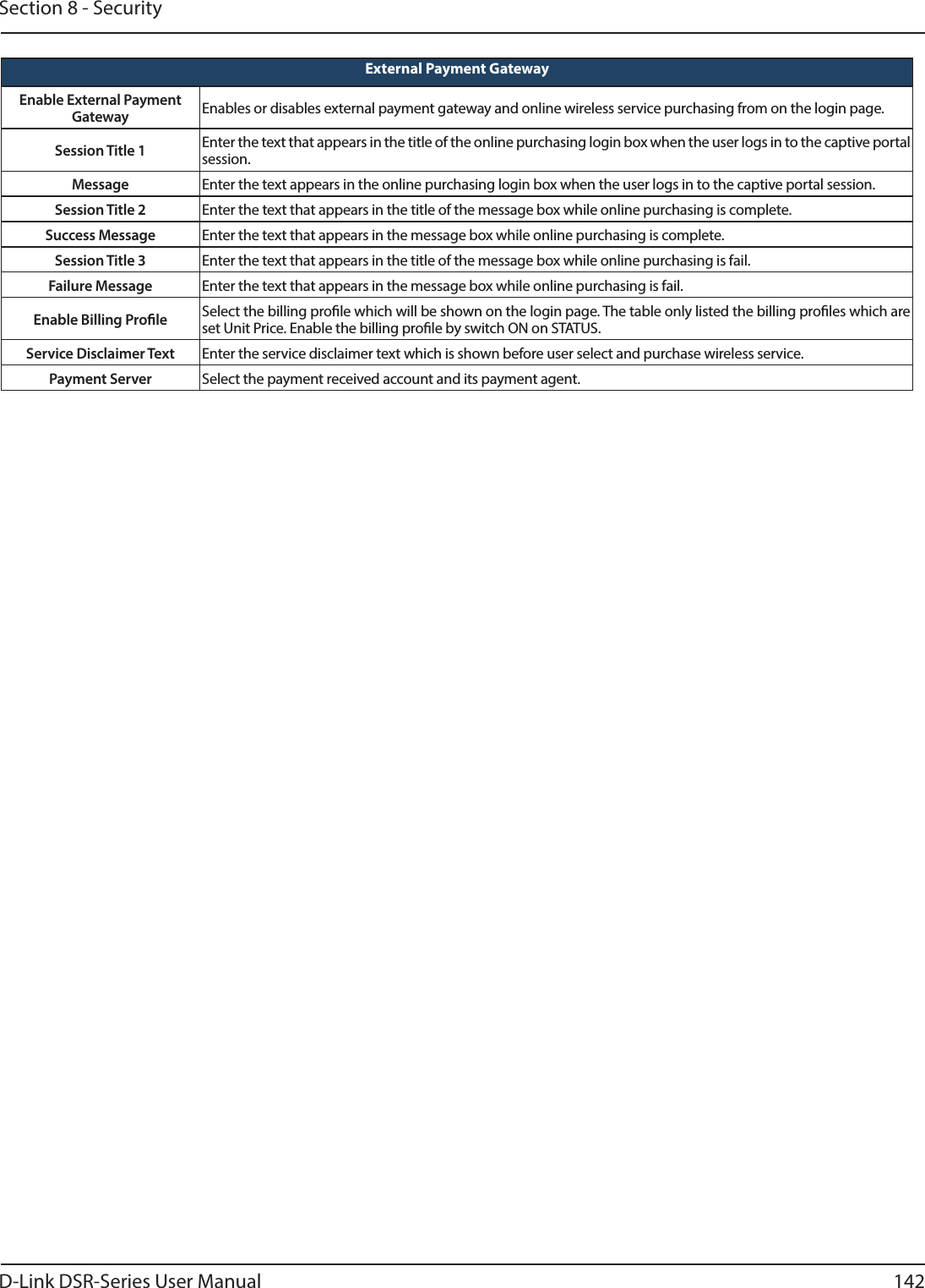
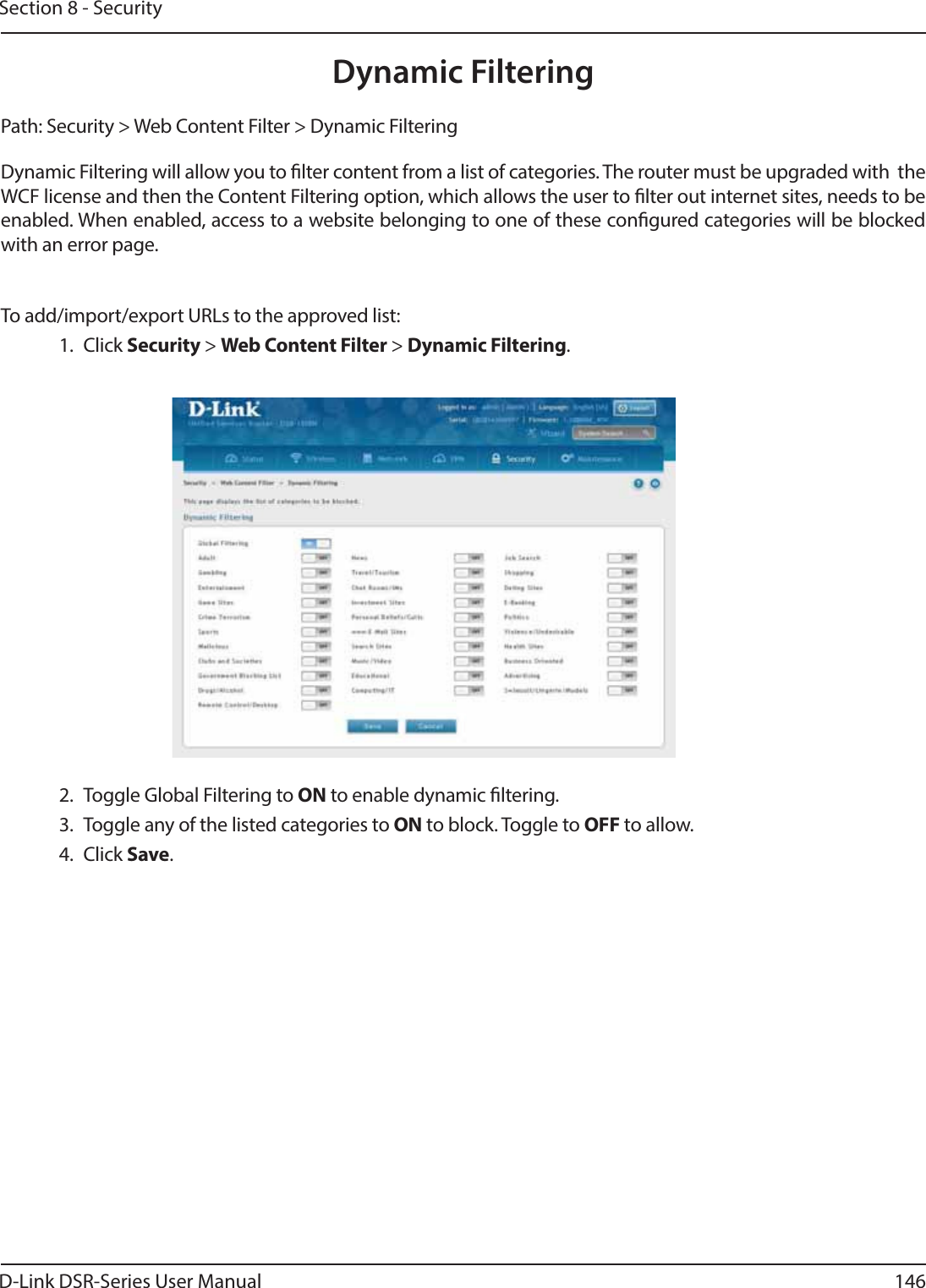
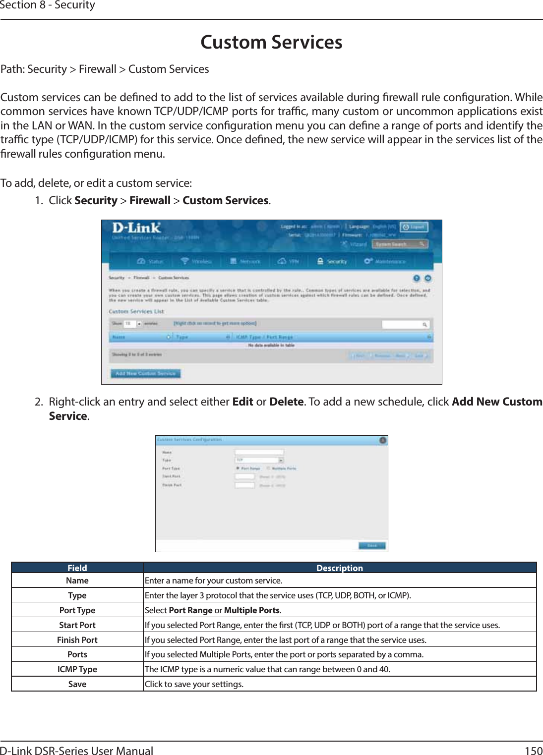
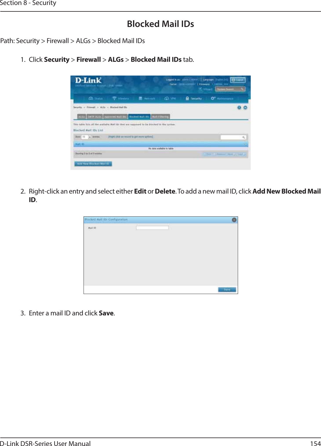
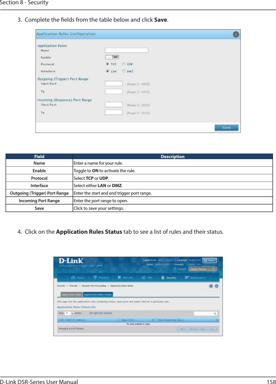
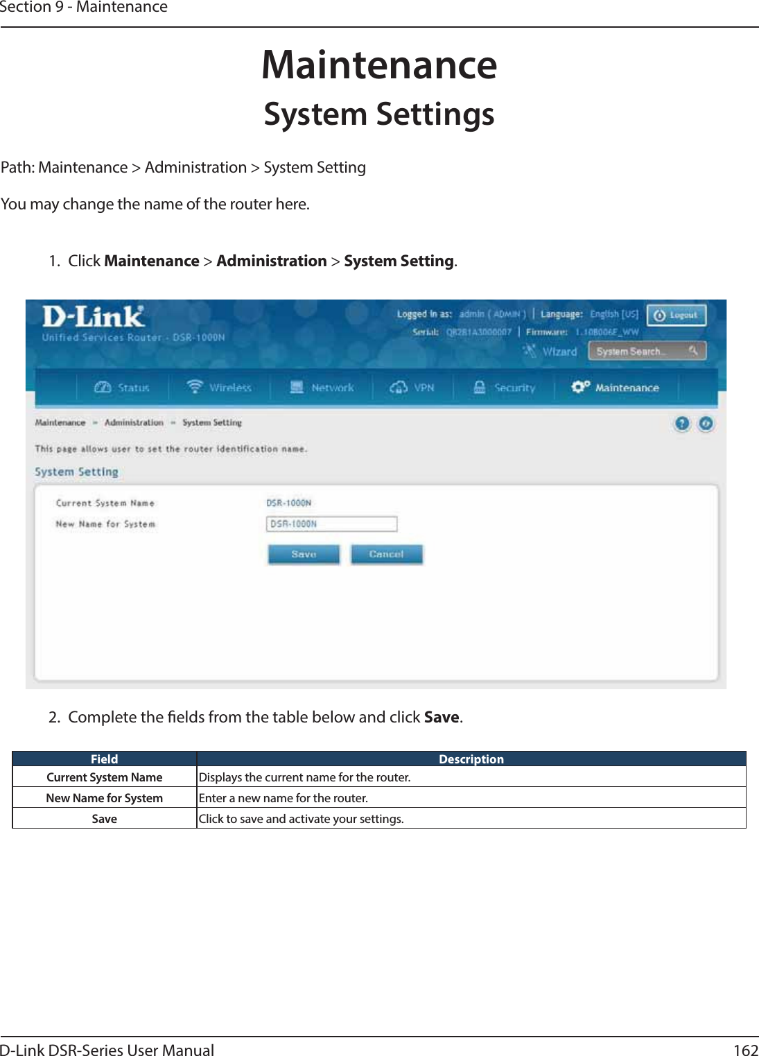
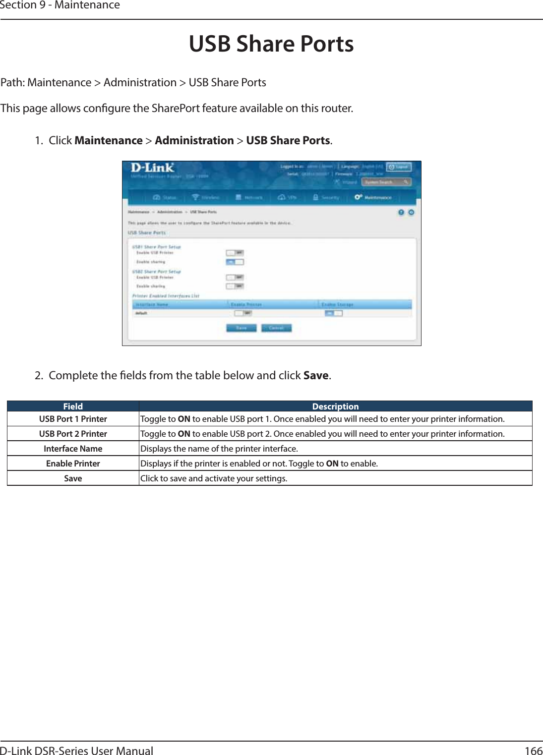
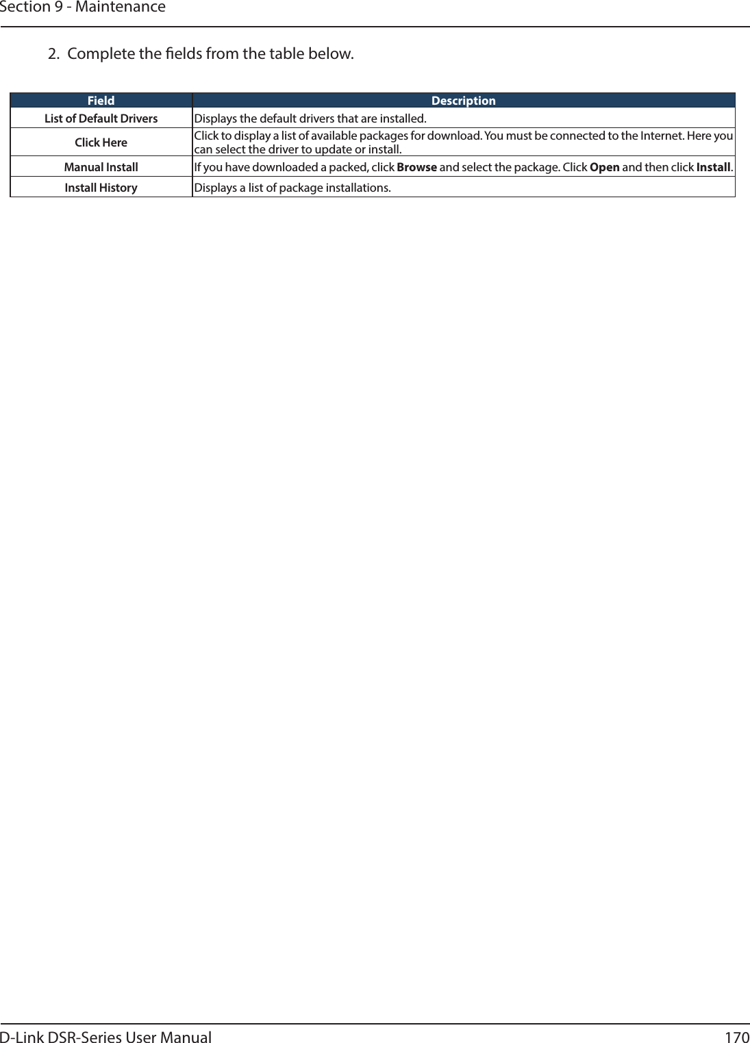
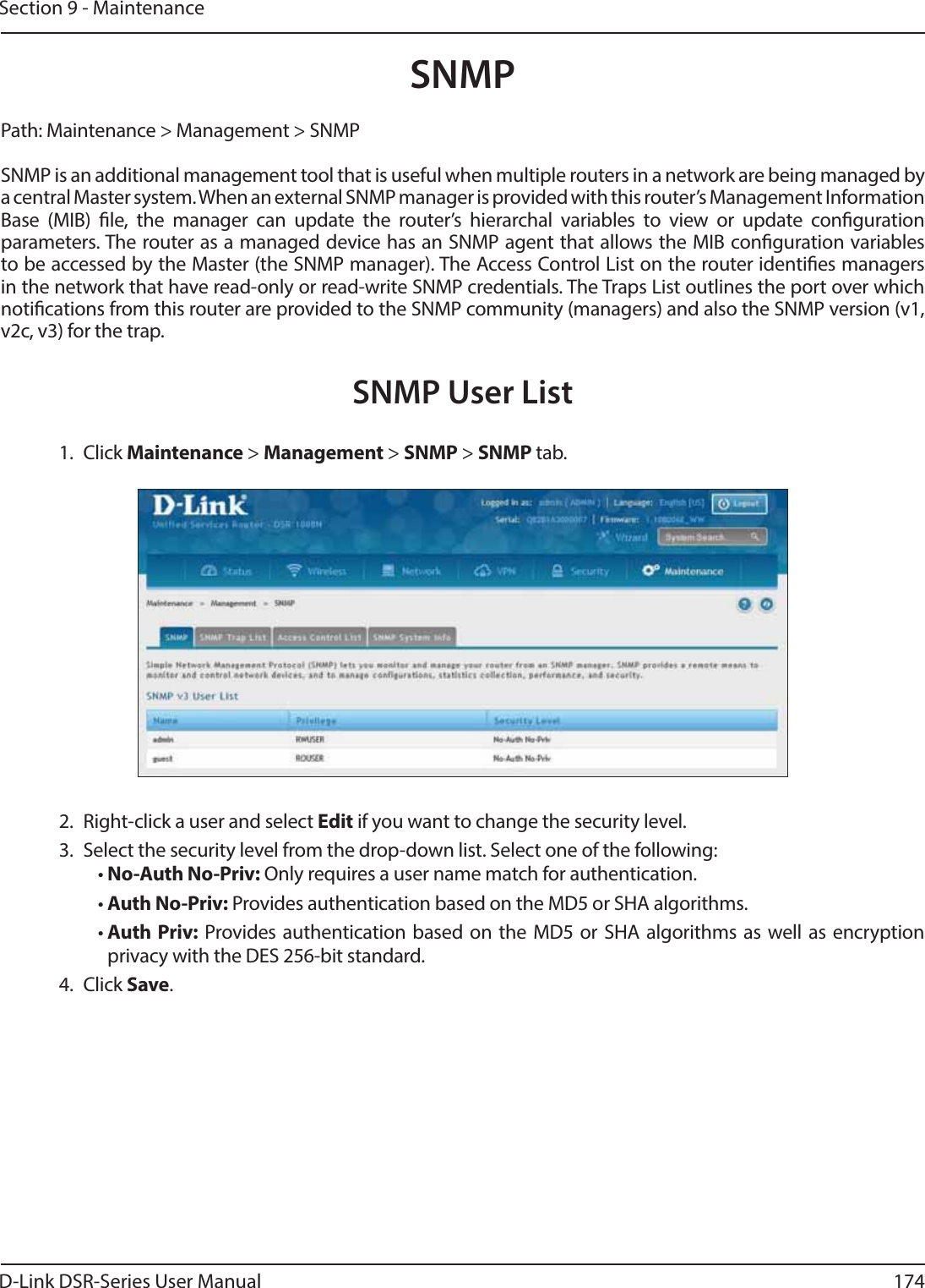
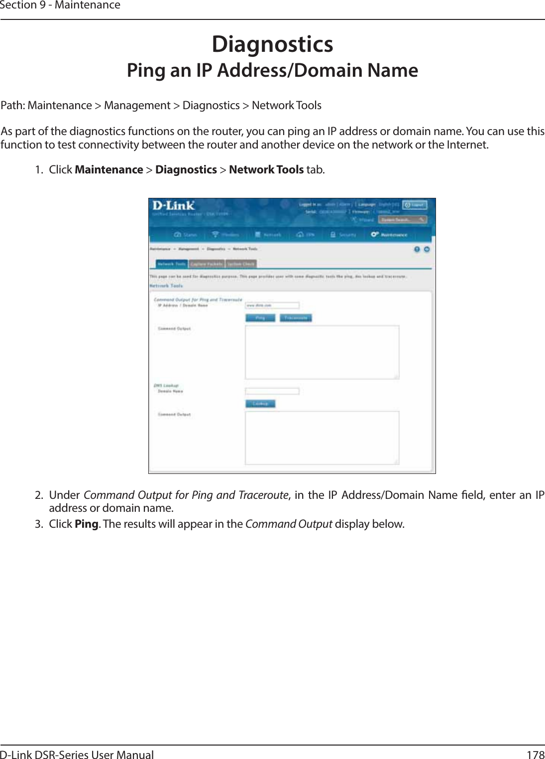
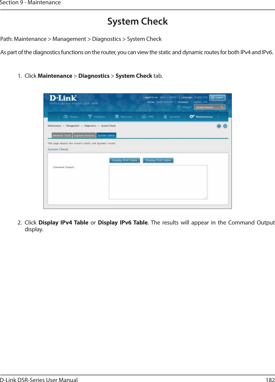
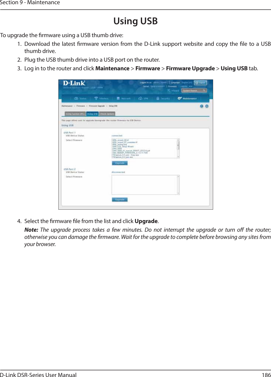
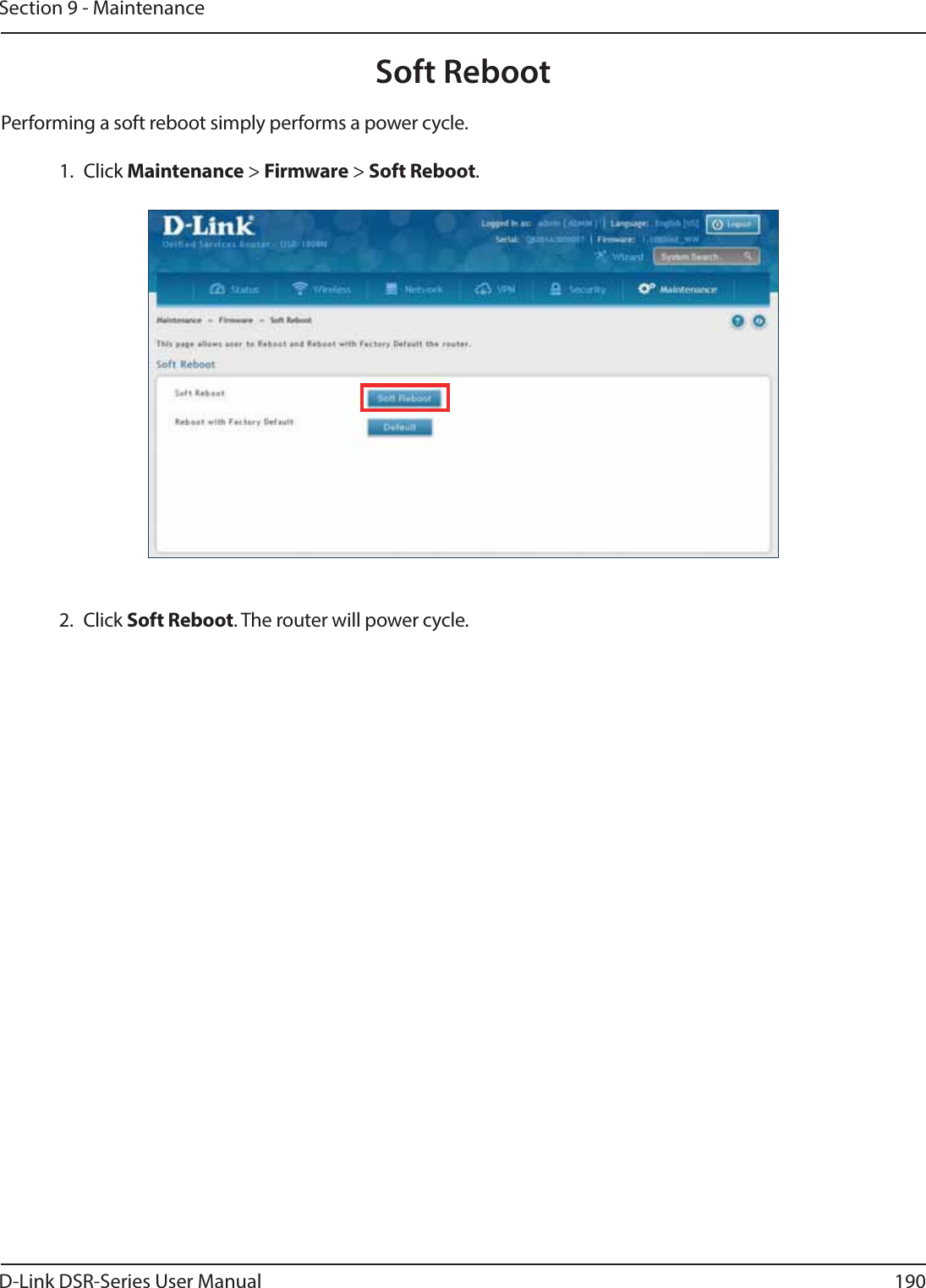
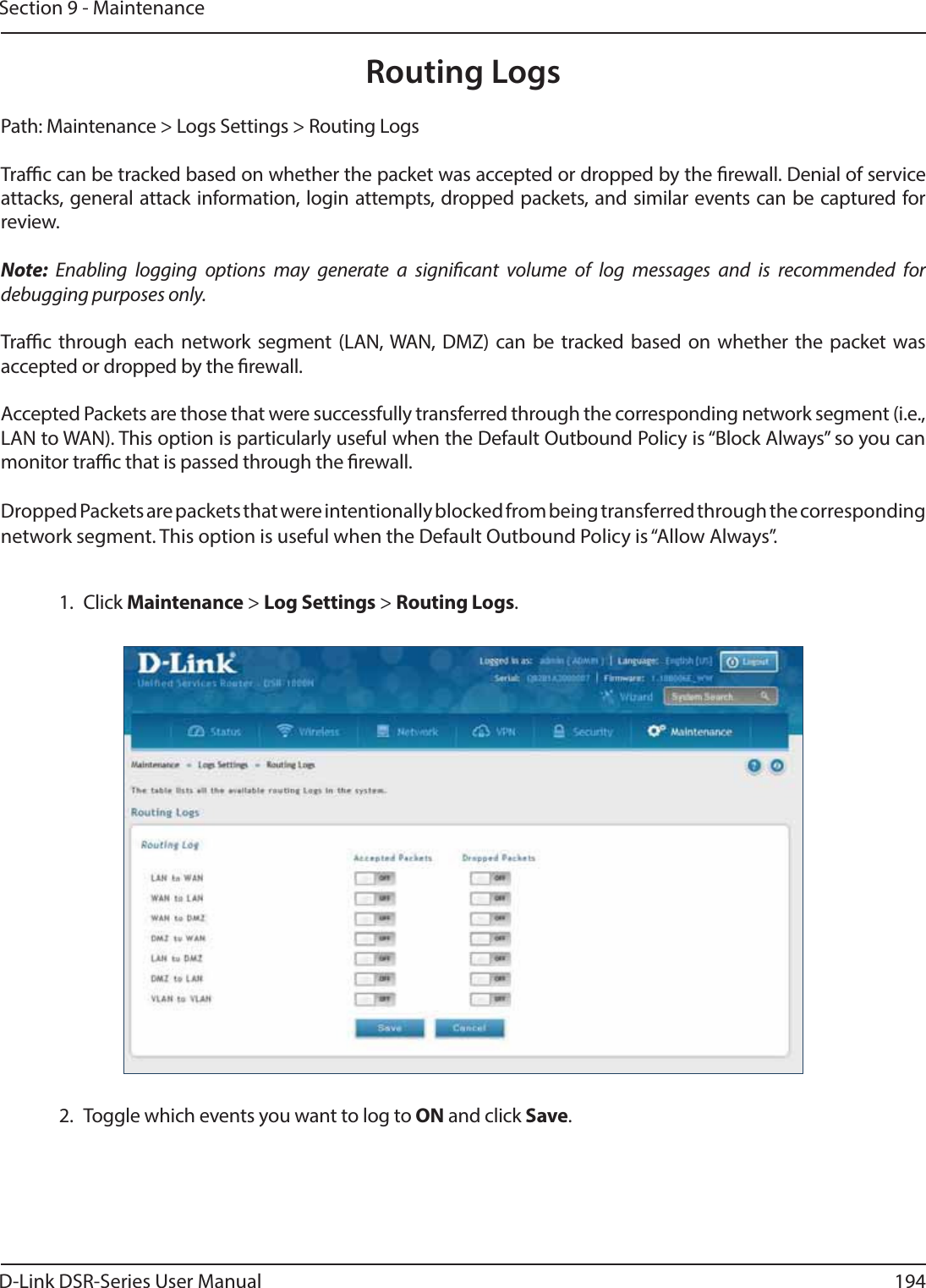
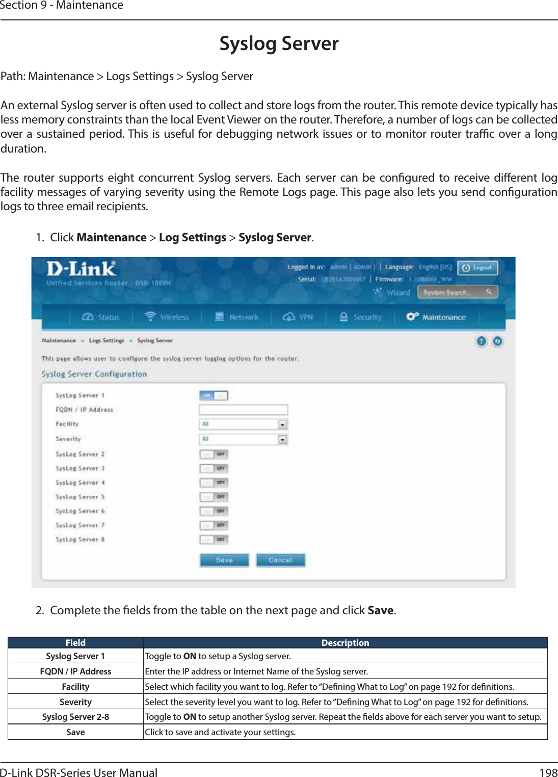
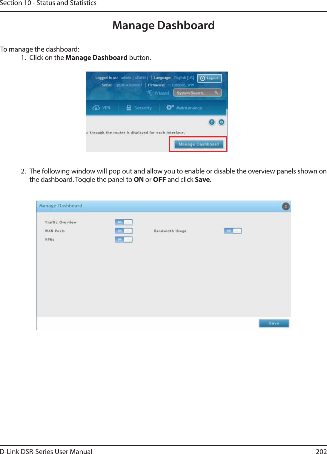
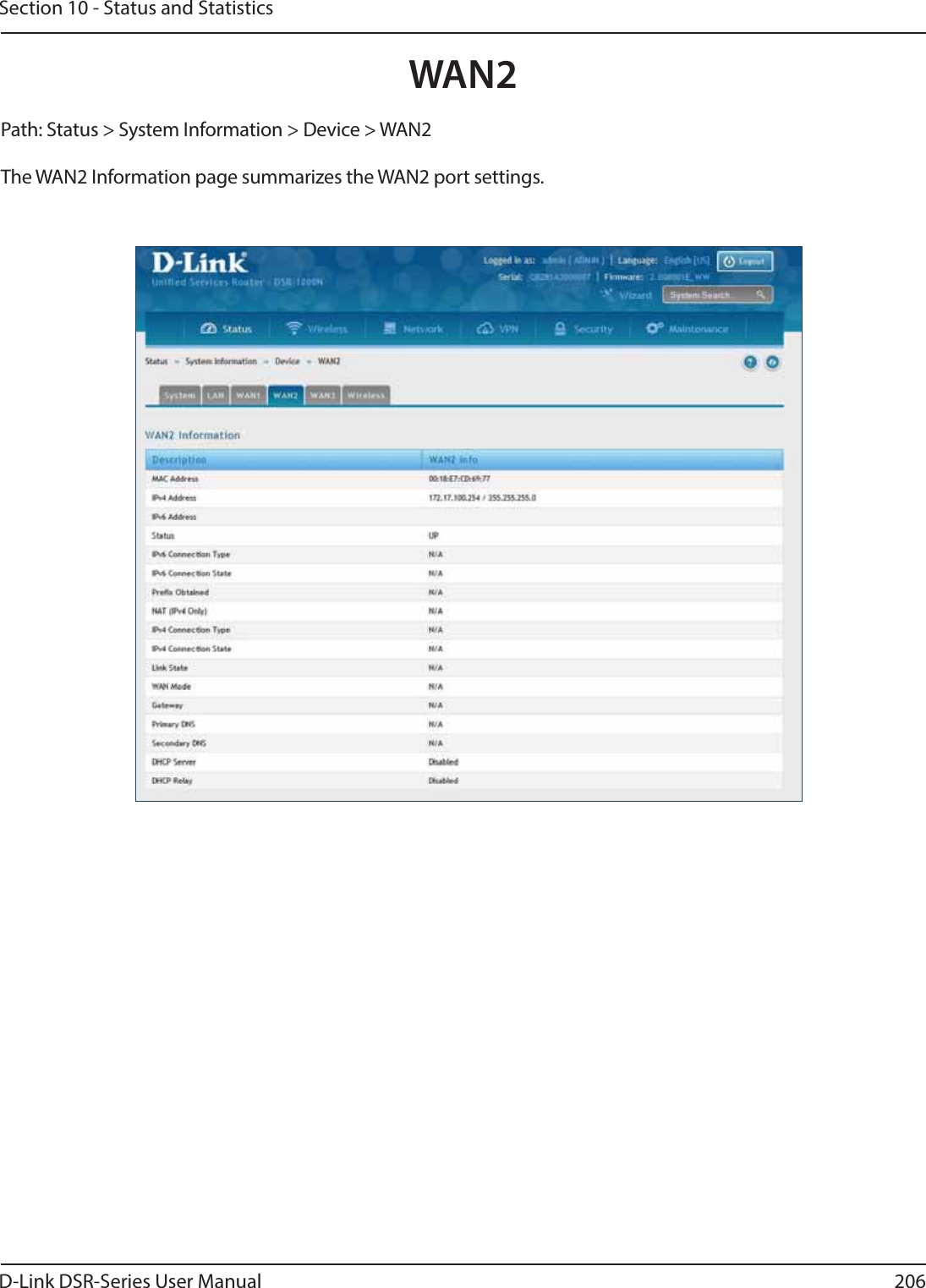
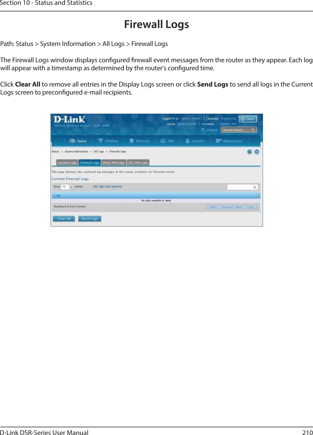
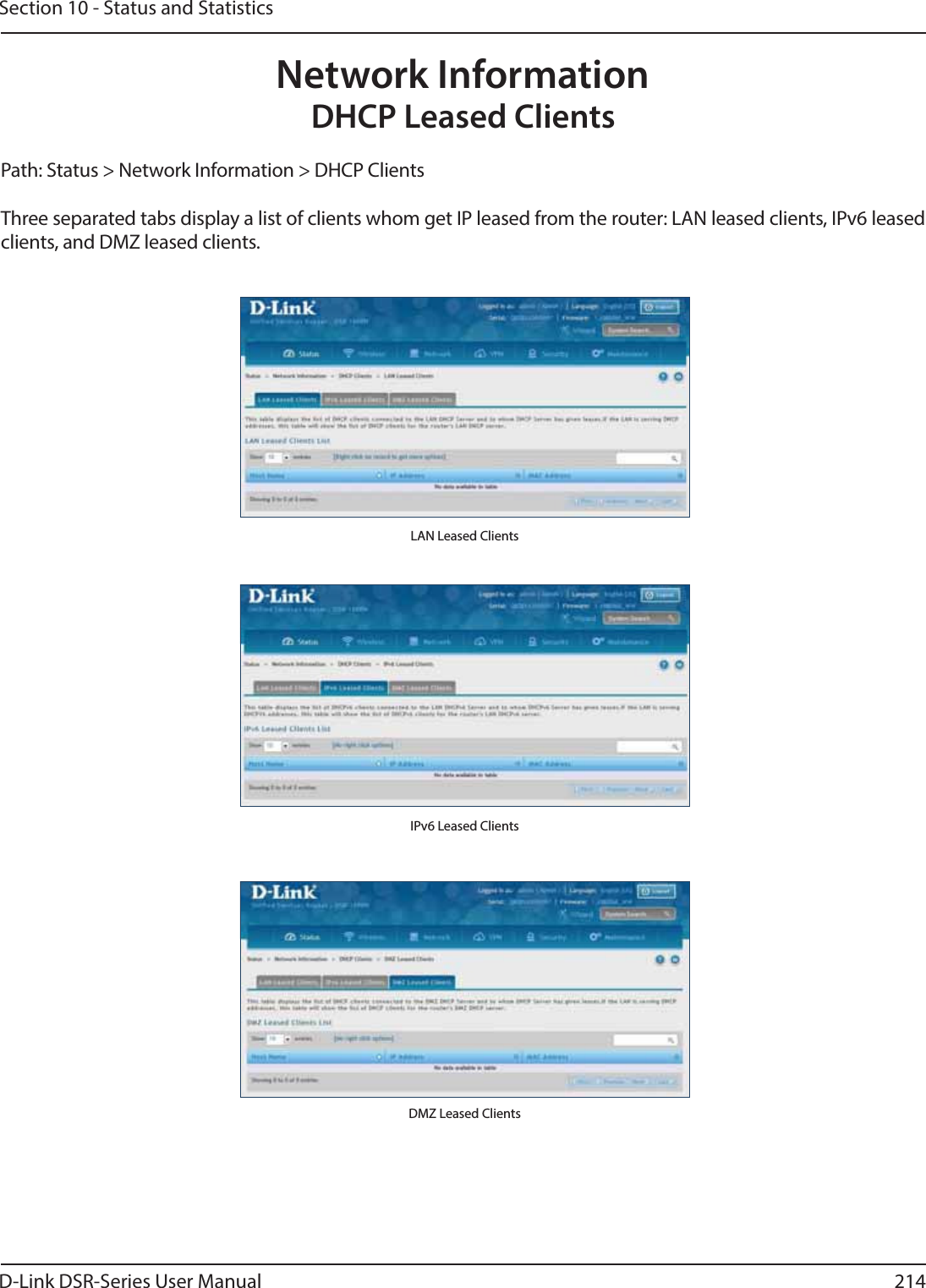
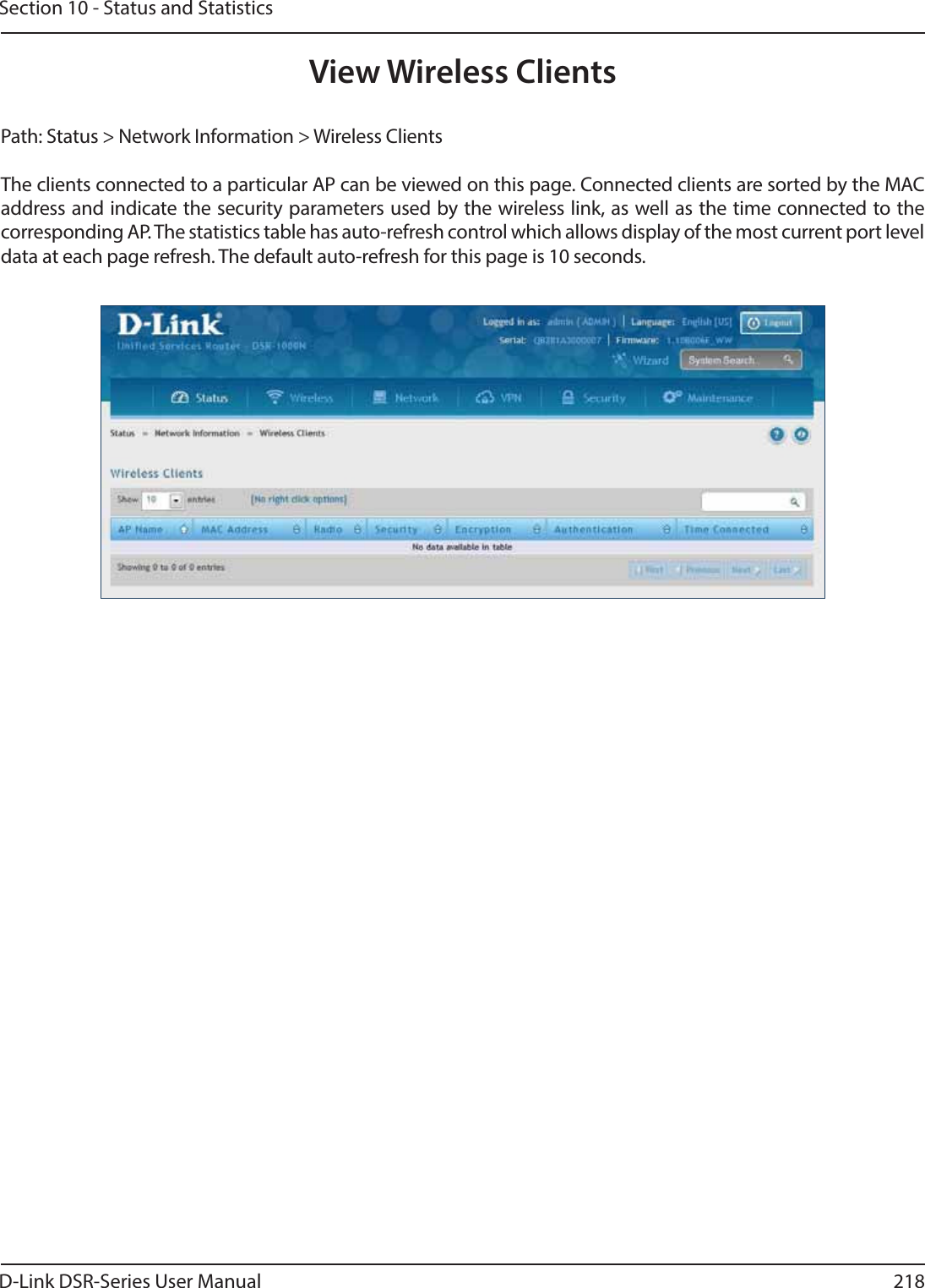
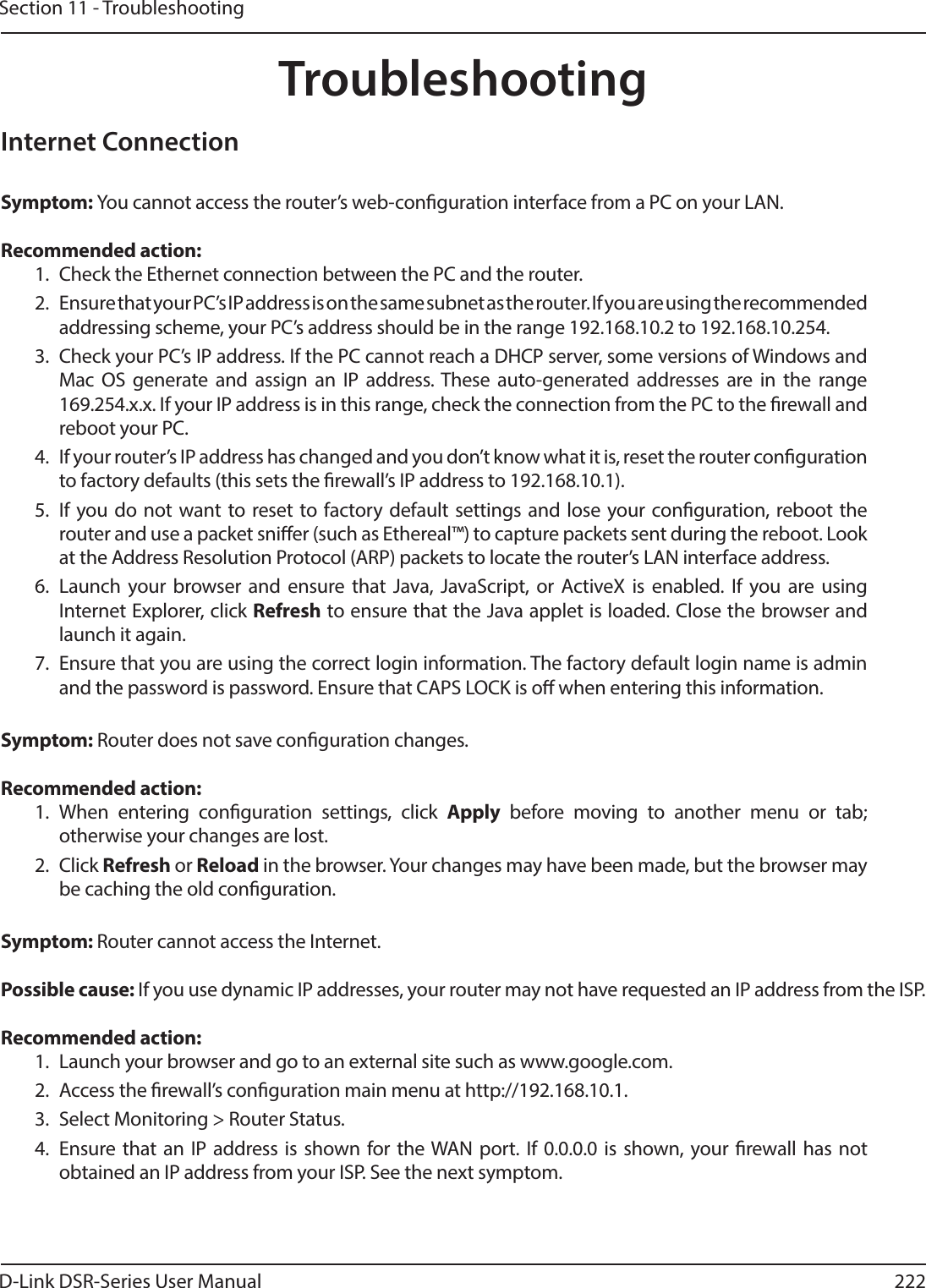
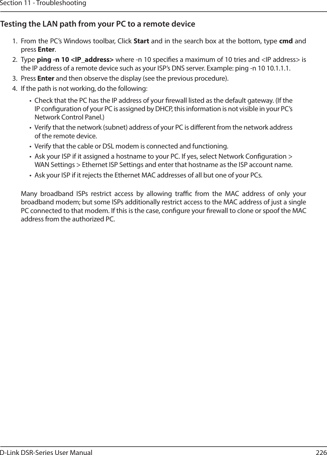
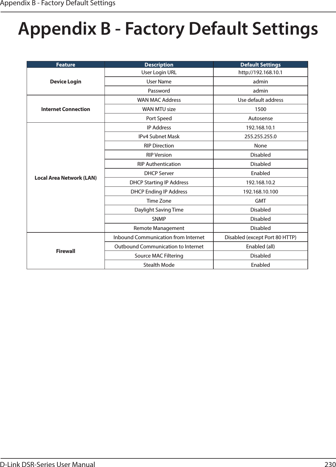
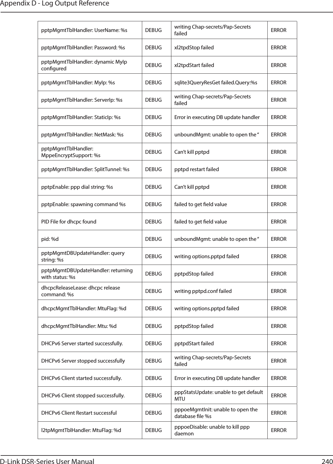
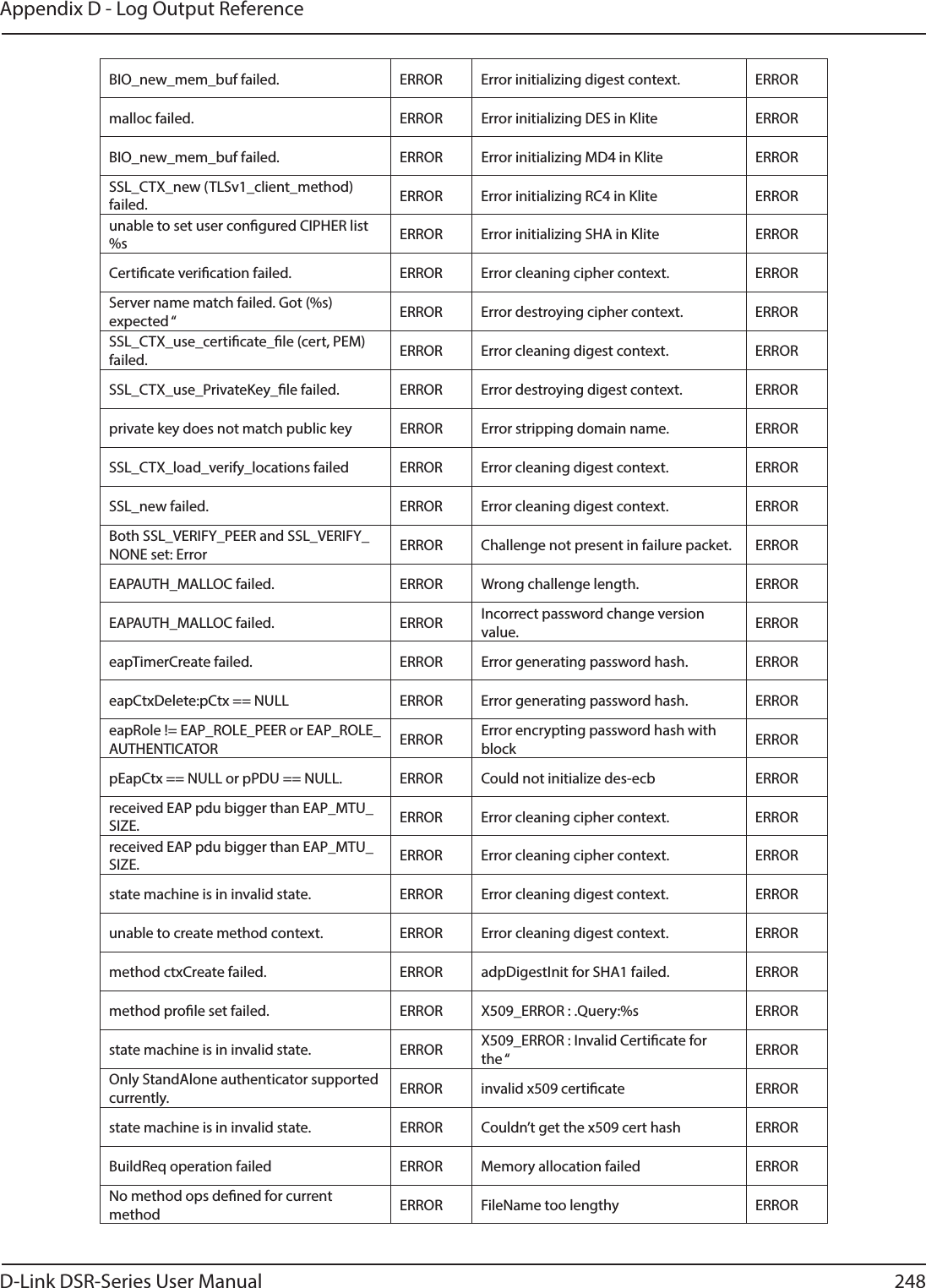
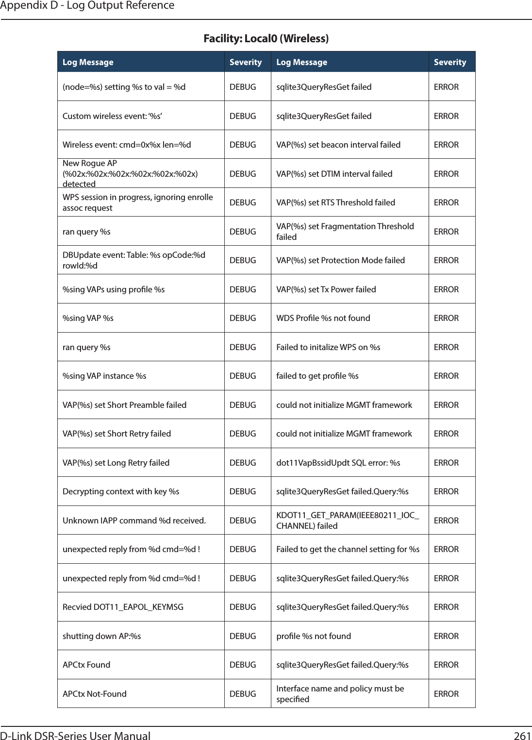
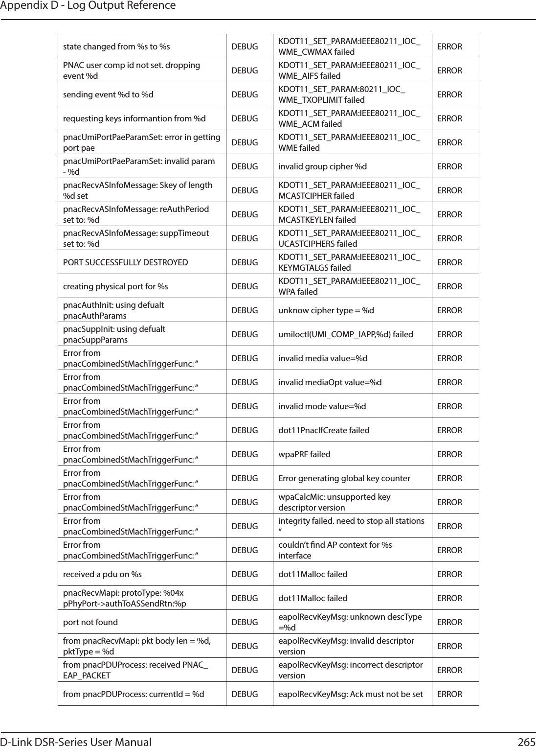
![D-Link DSR-Series User Manual 93Section 7 - VPNField DescriptionPolicy Name Enter a unique name for the VPN Policy. This name is not an identier for the remote WAN/client.Policy TypeSelect either Manual or Auto. • Manual: All settings (including the keys) for the VPN tunnel are manually input for each end point. No third-party server or organization is involved.• Auto: Some parameters for the VPN tunnel are generated automatically. This requires using the IKE (Internet Key Exchange) protocol to perform negotiations between the two VPN Endpoints.IP Protocol Version Select either IPv4 or IPv6.IKE Version Select the version of IKE.IPSec ModeSelect either Tunnel or Transport. IPsec tunnel mode is useful for protecting trac between dierent networks, when trac must pass through an intermediate, untrusted network. Tunnel mode is primarily used for interoperability with gateways, or end-systems that do not support L2TP/IPsec or PPTP connections. Transport mode is the default mode for IPsec, and it is used for end-to-end communications (for example, for communications between a client and a server).Select Local Gateway In the event that two WAN ports are congured to connect to your ISP, select the gateway that will be used as the local endpoint for this IPsec tunnel.Remote Endpoint Select the type of identier that you want to provide for the router at the remote endpoint (either IP Address or FQDN [Fully Qualied Domain Name])IP Address/FQDN Enter the identier for the router.Enable Mode Cong Toggle to ON to enable. Mode Cong is similar to DHCP and is used to assign IP addresses to the remote VPN clients.Enable NetBIOS Toggle to ON to allow NetBIOS broadcasts to travel over the VPN tunnelEnable RollOver Toggle to ON to enable VPN rollover. You must have the WAN Mode set to Rollover.Protocol Select a protocol from the drop-down menu.Enable DHCP Toggle to ON to allow VPN clients that are connected to your router over IPsec to receive an assigned IP using DHCP.Local IP/Remote IPSelect the type of identier that you want to provide for the endpoint:• Any: Species that the policy is for trac from the given end point (local or remote). Note that selecting Any for both local and remote end points is not valid.• Single: Limits the policy to one host. Enter the IP address of the host that will be part of the VPN.• Range: Allows computers within an IP address range to connect to the VPN. Enter the Start IP Address and End IP Address in the provided elds.• Subnet: Allows an entire subnet to connect to the VPN. Enter the network address and subnet mask in the provided elds.Enable Keepalive Toggle to ON to periodically send ping packets to the host on the peer side of the network to keep the tunnel alive.](https://usermanual.wiki/D-Link/SR500ACA1/User-Guide-2623752-Page-106.png)
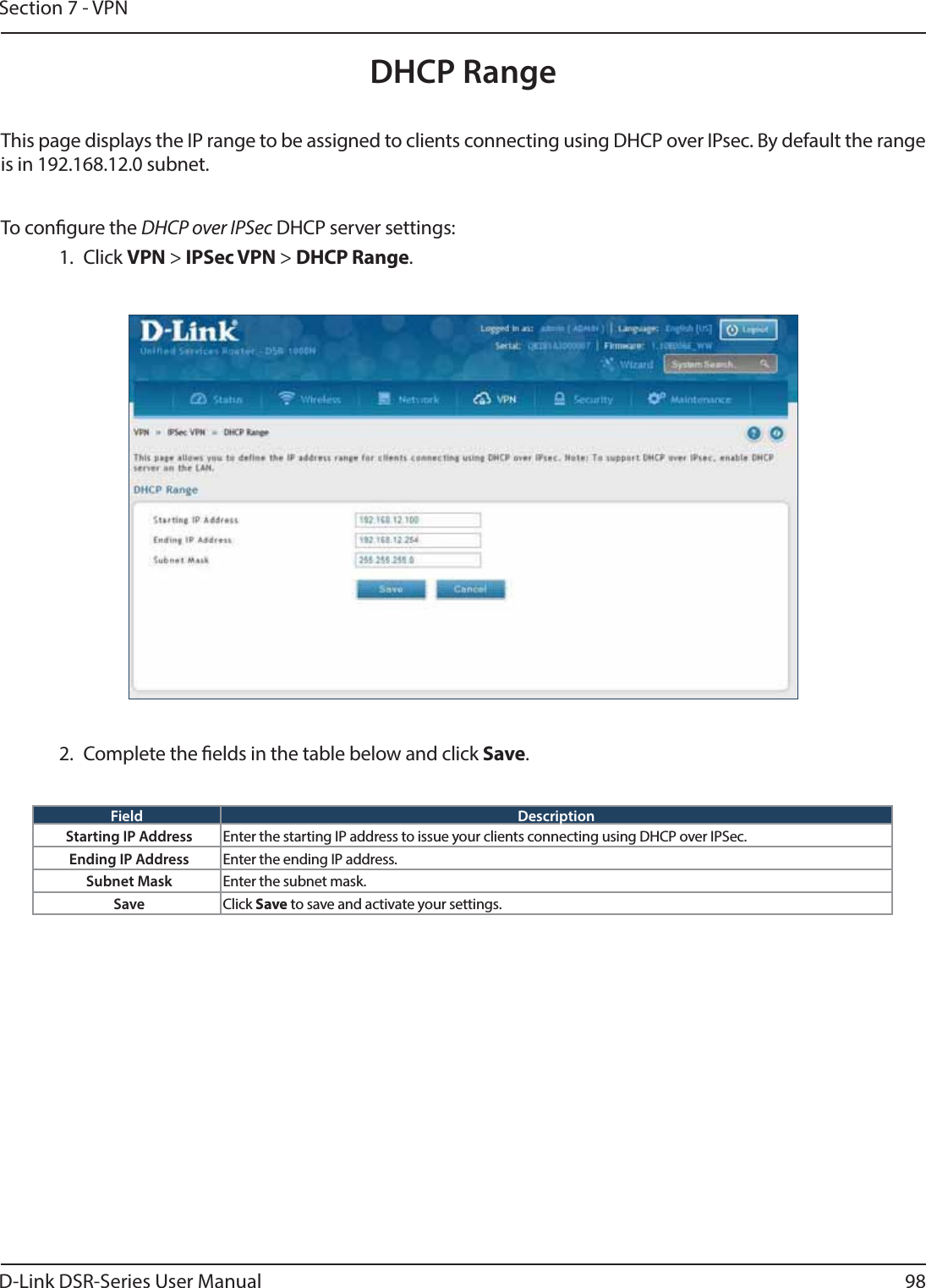
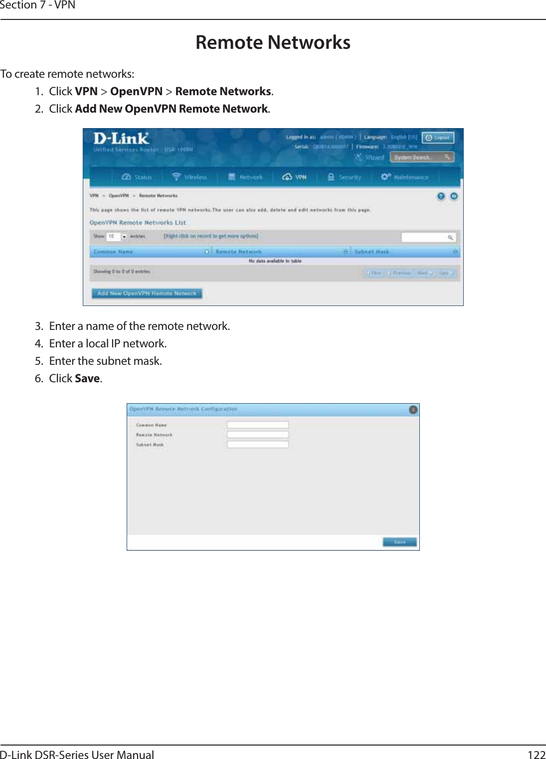

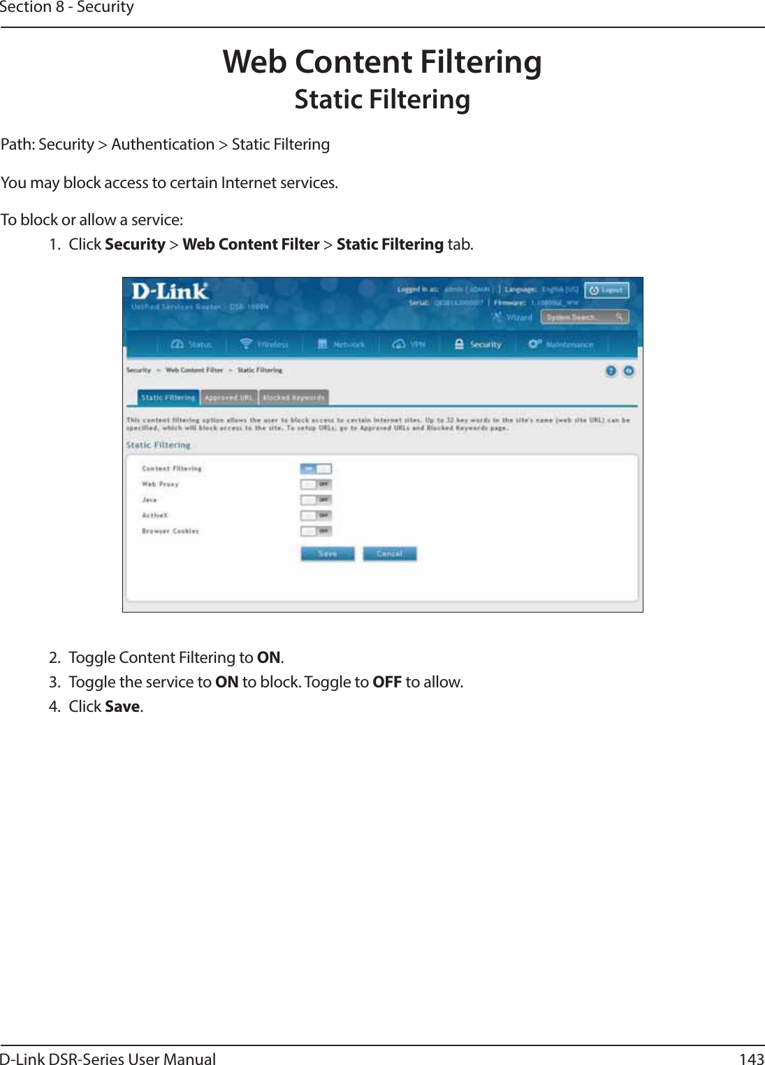
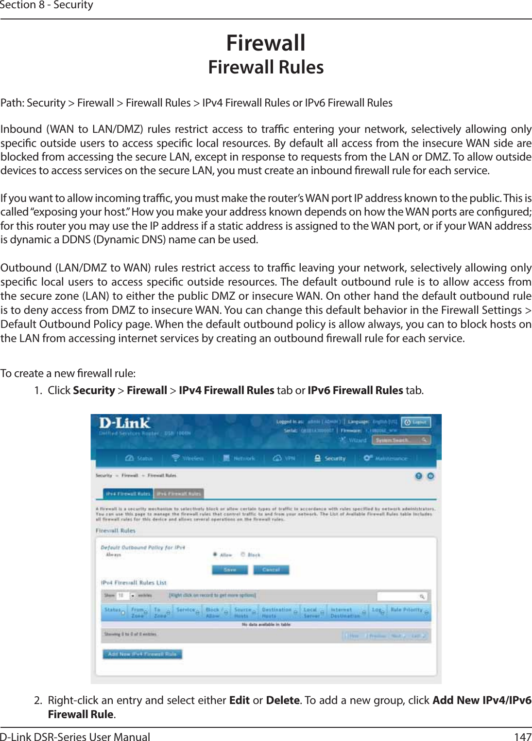
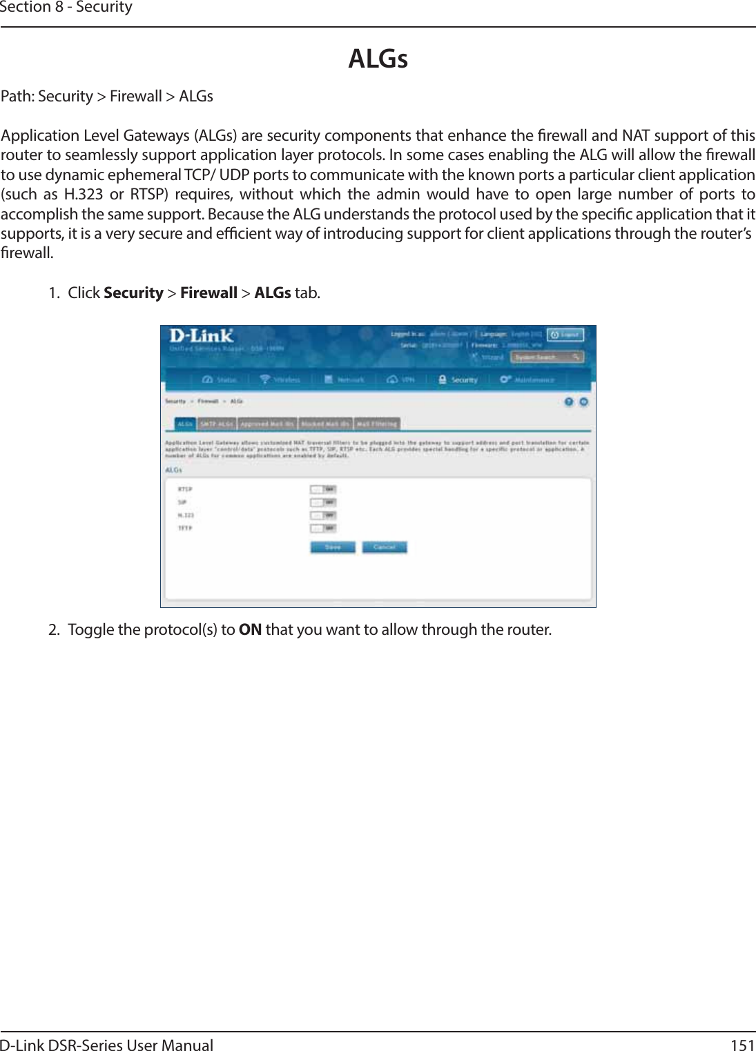
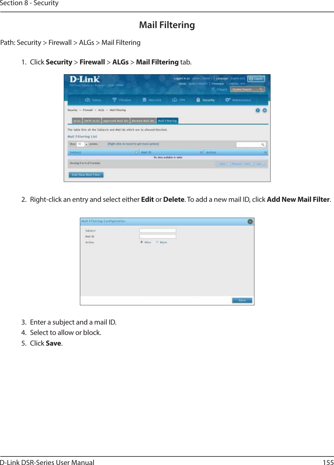
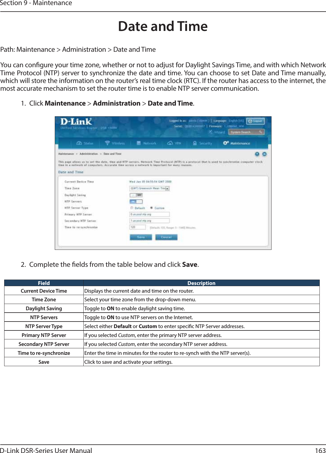
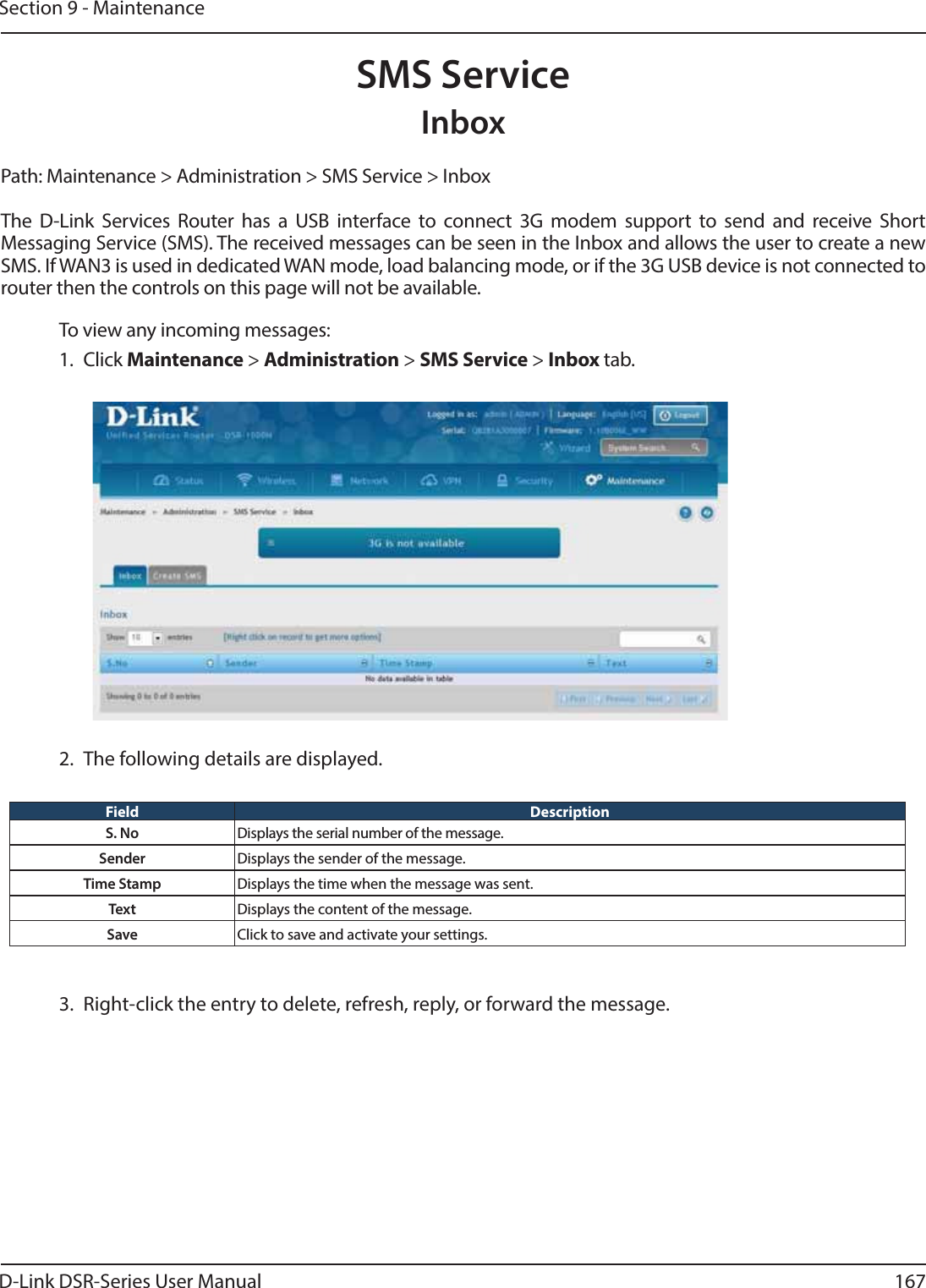
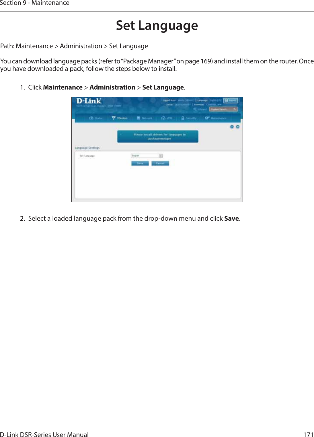
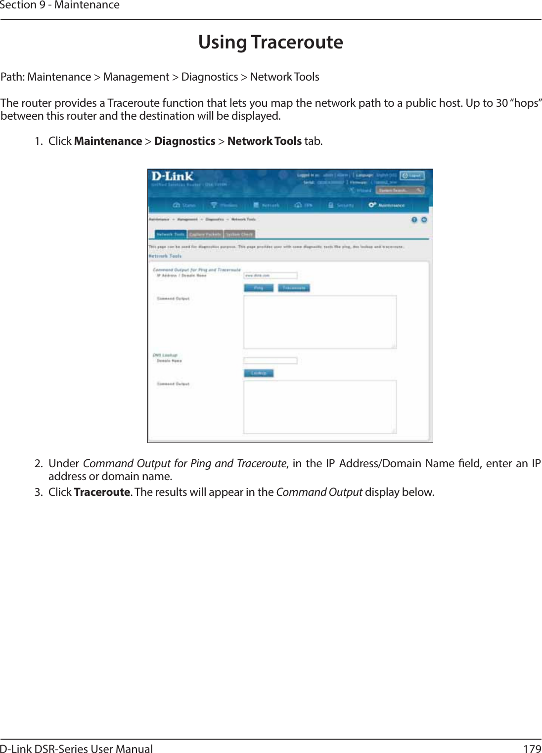
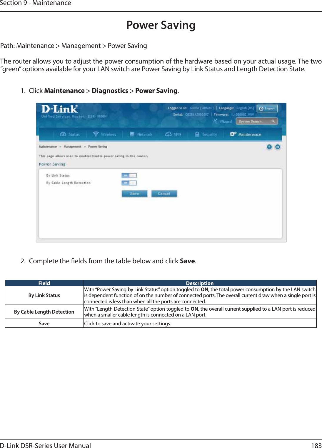
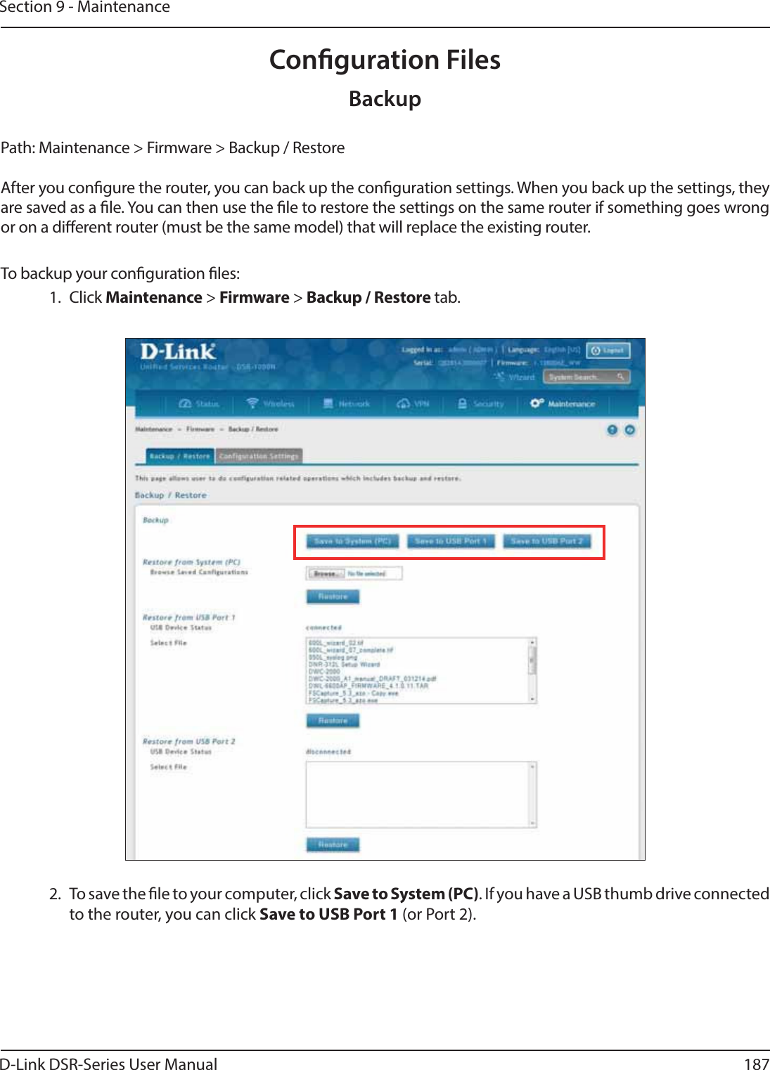
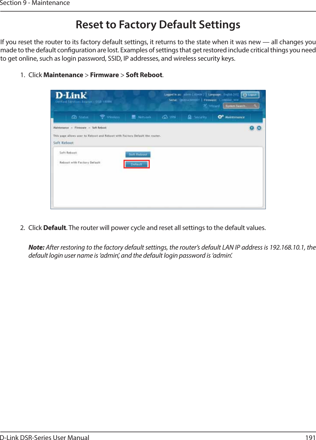
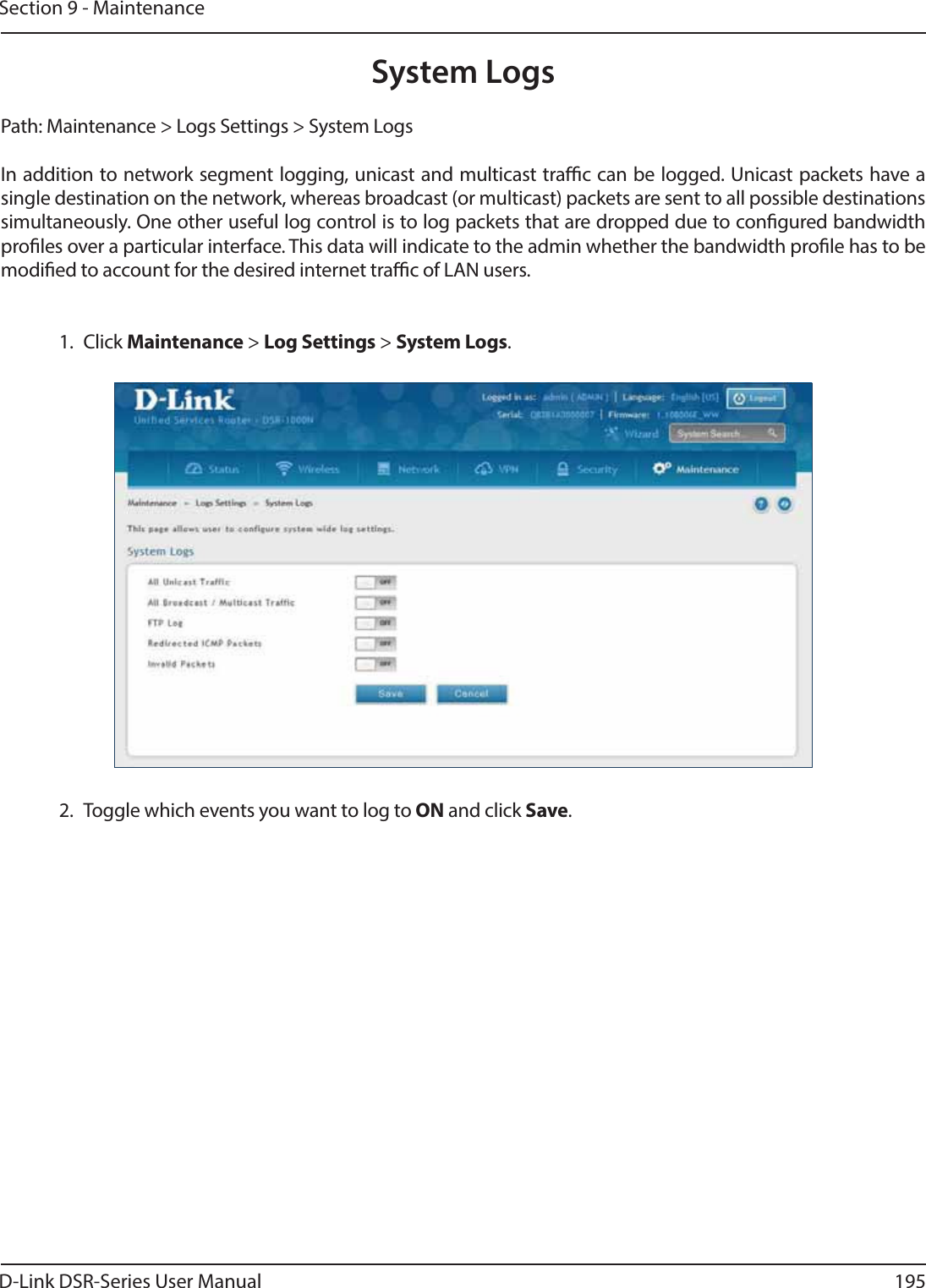
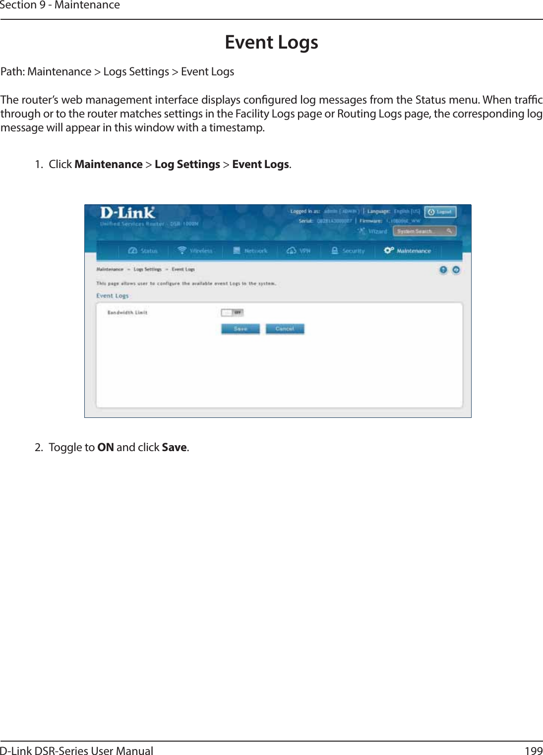
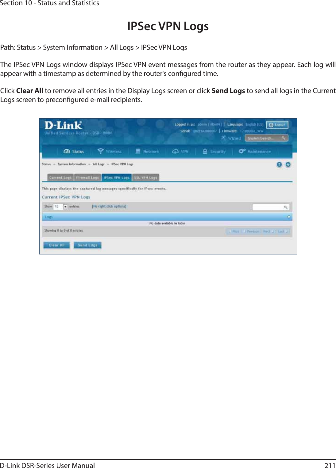
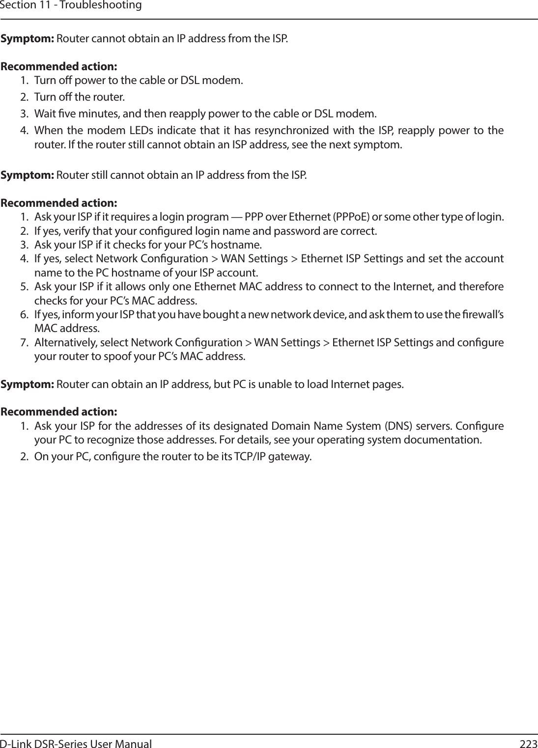
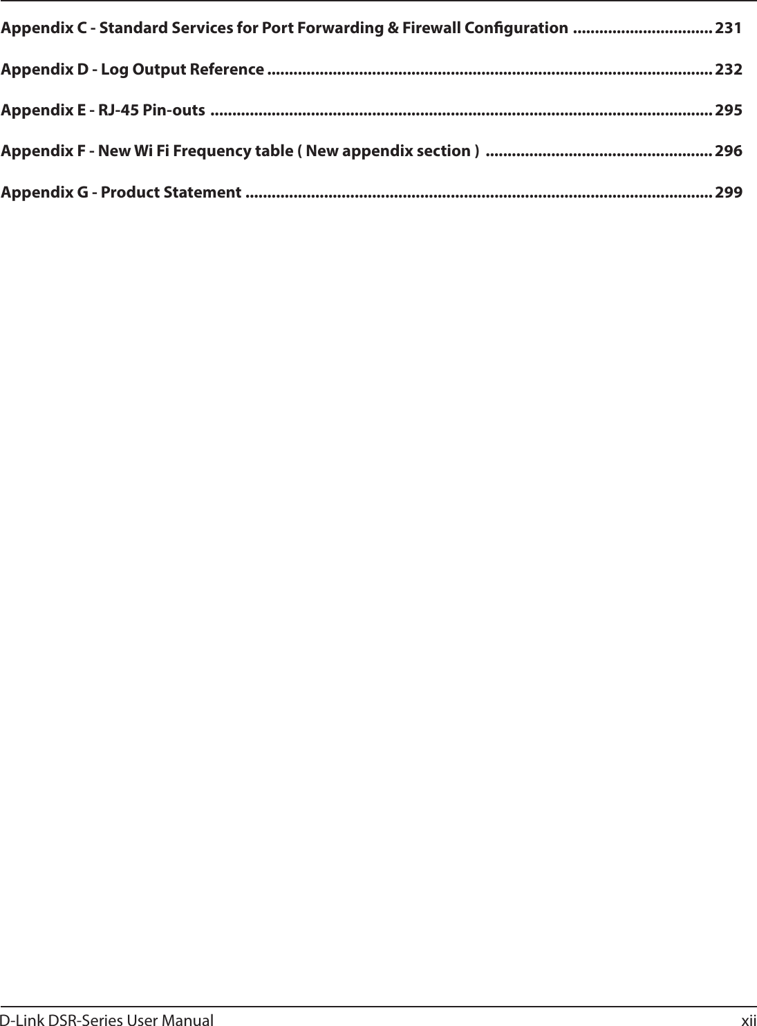
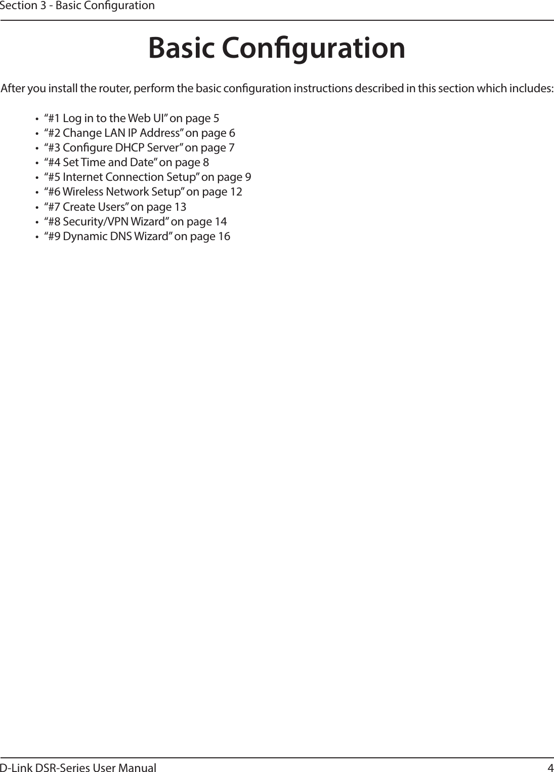
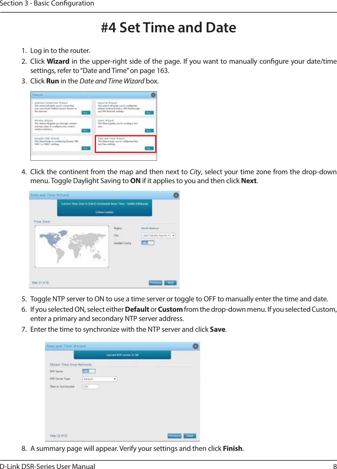
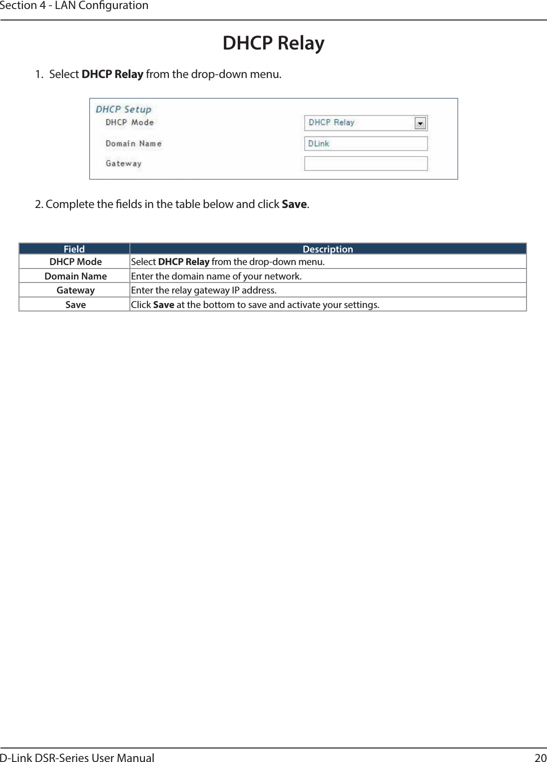
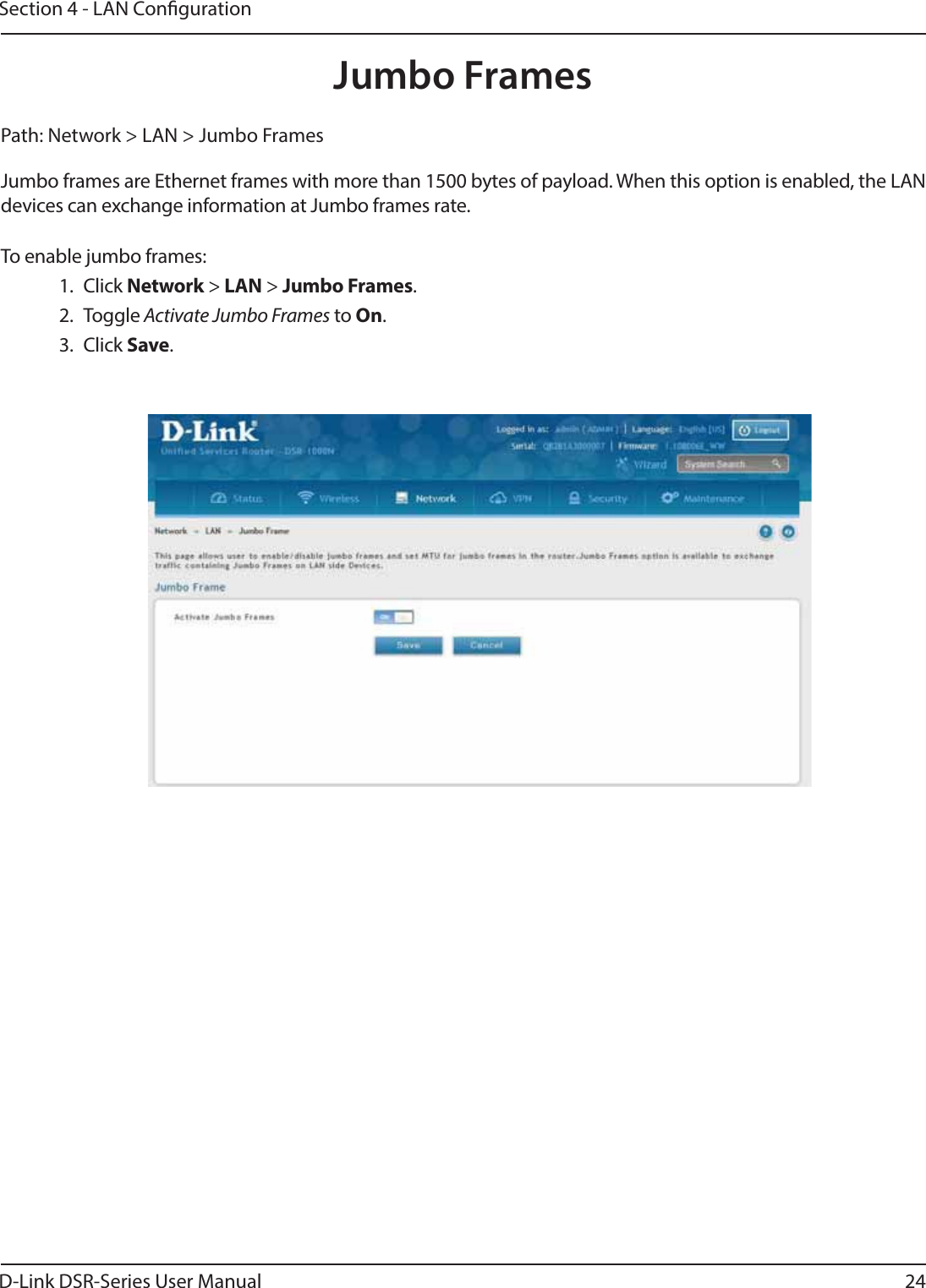
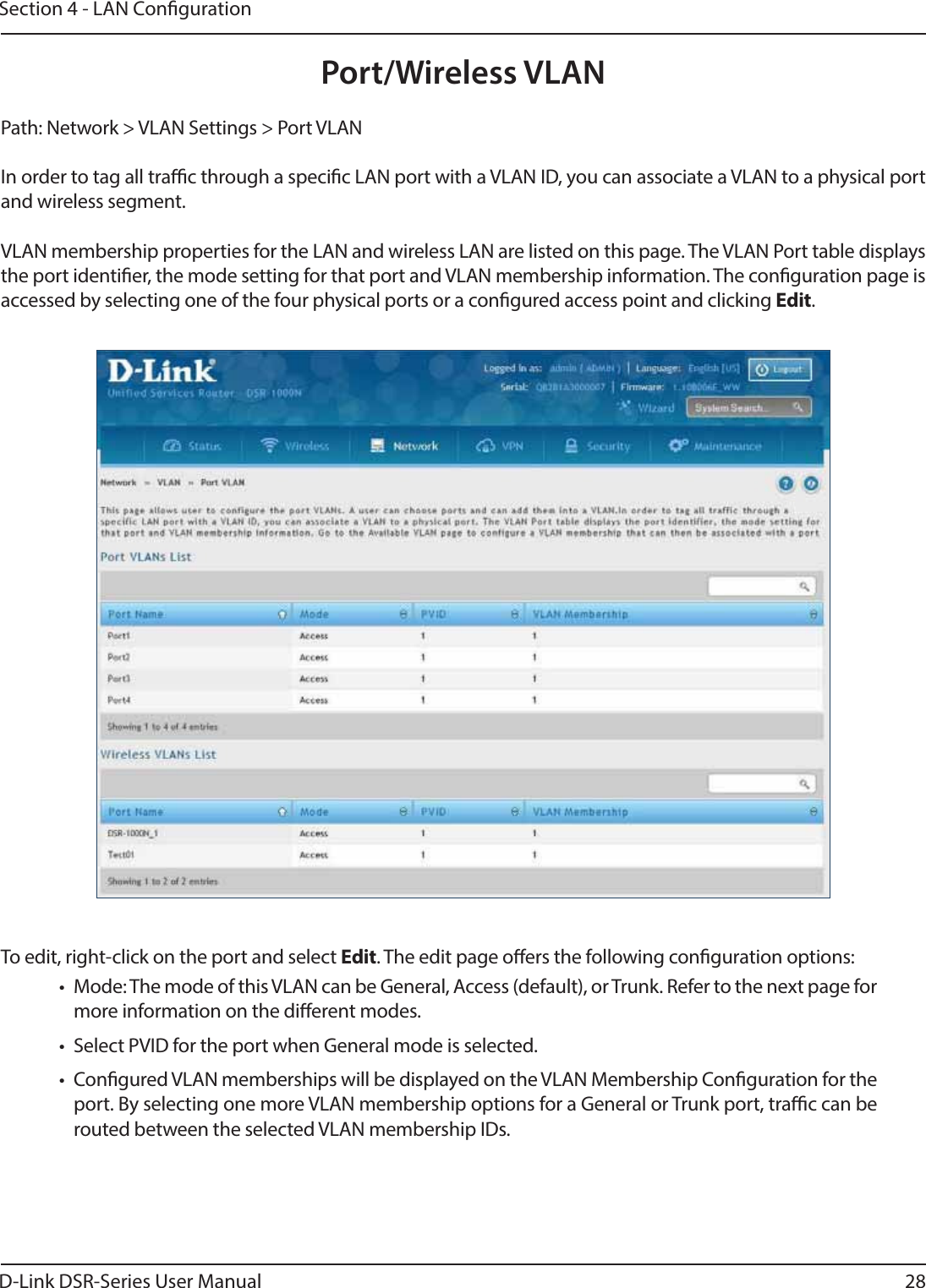
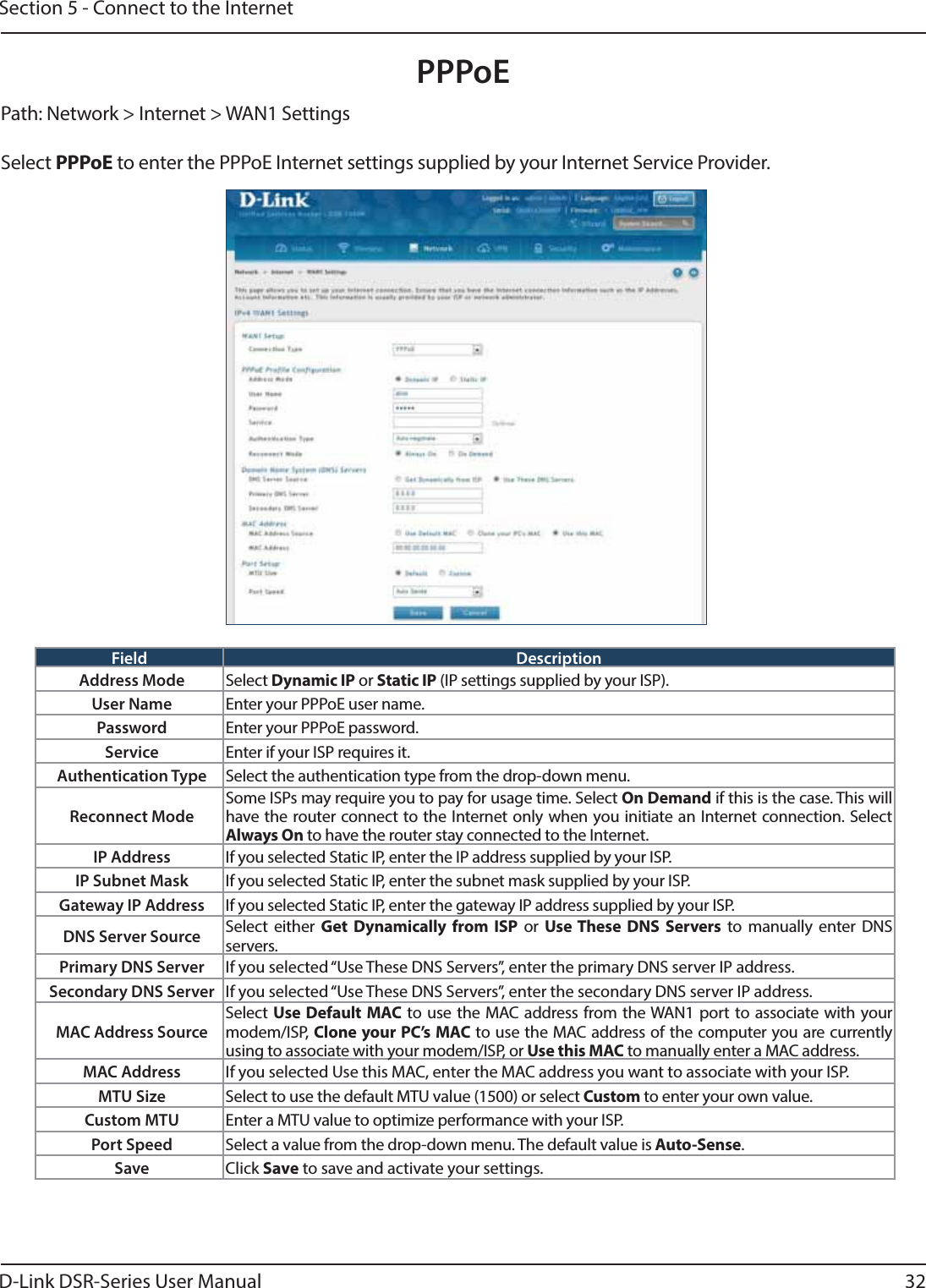
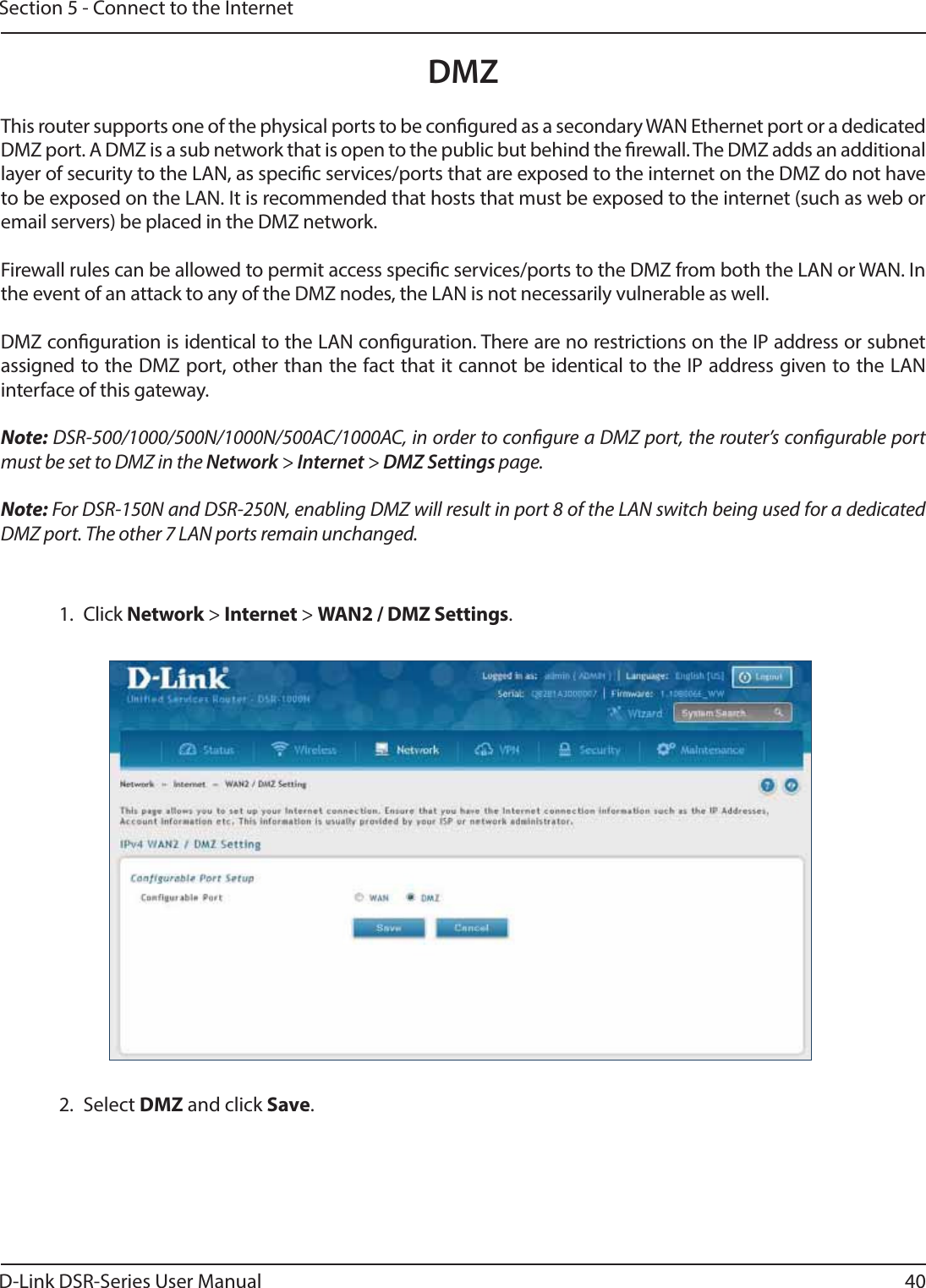
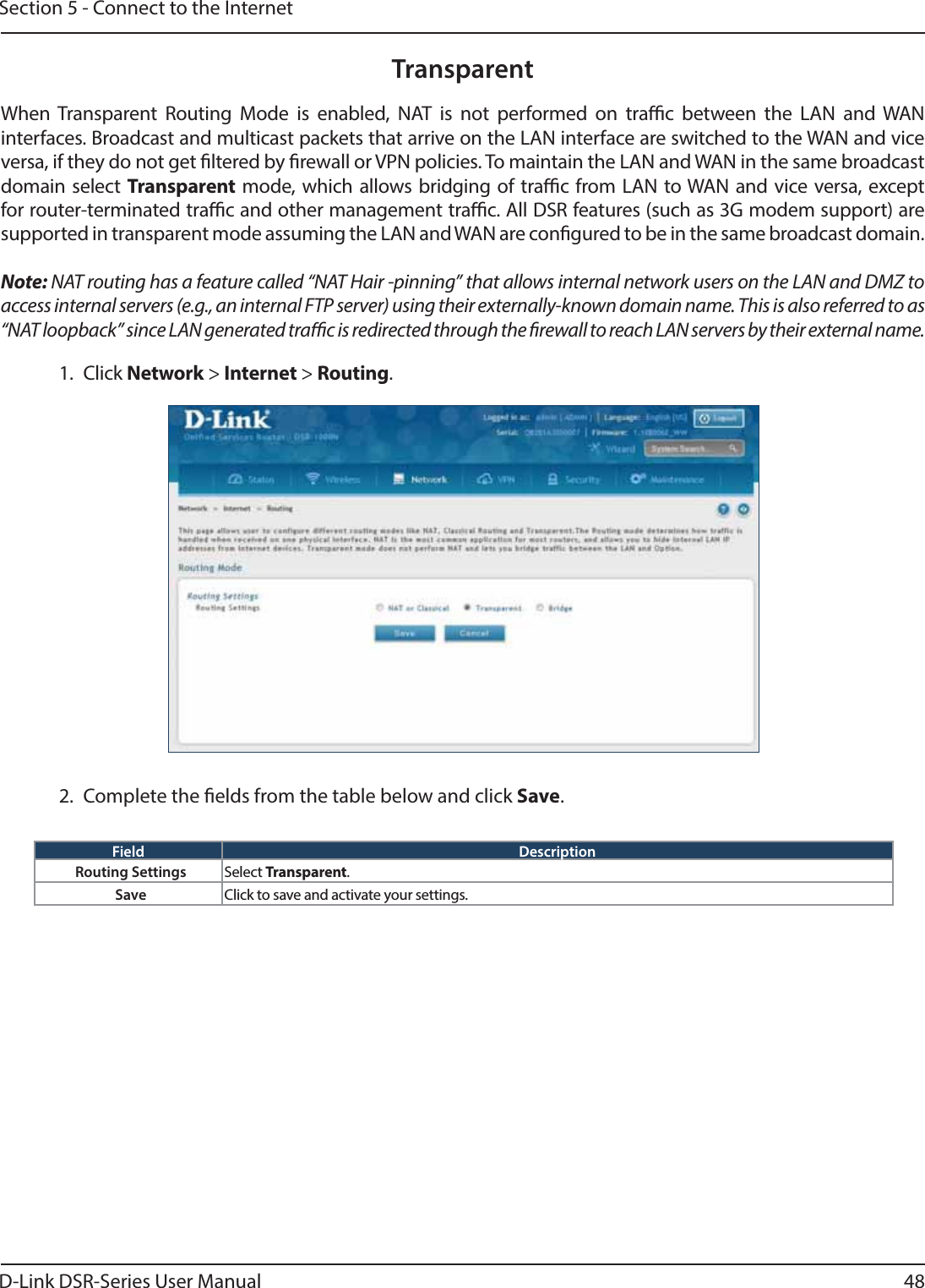
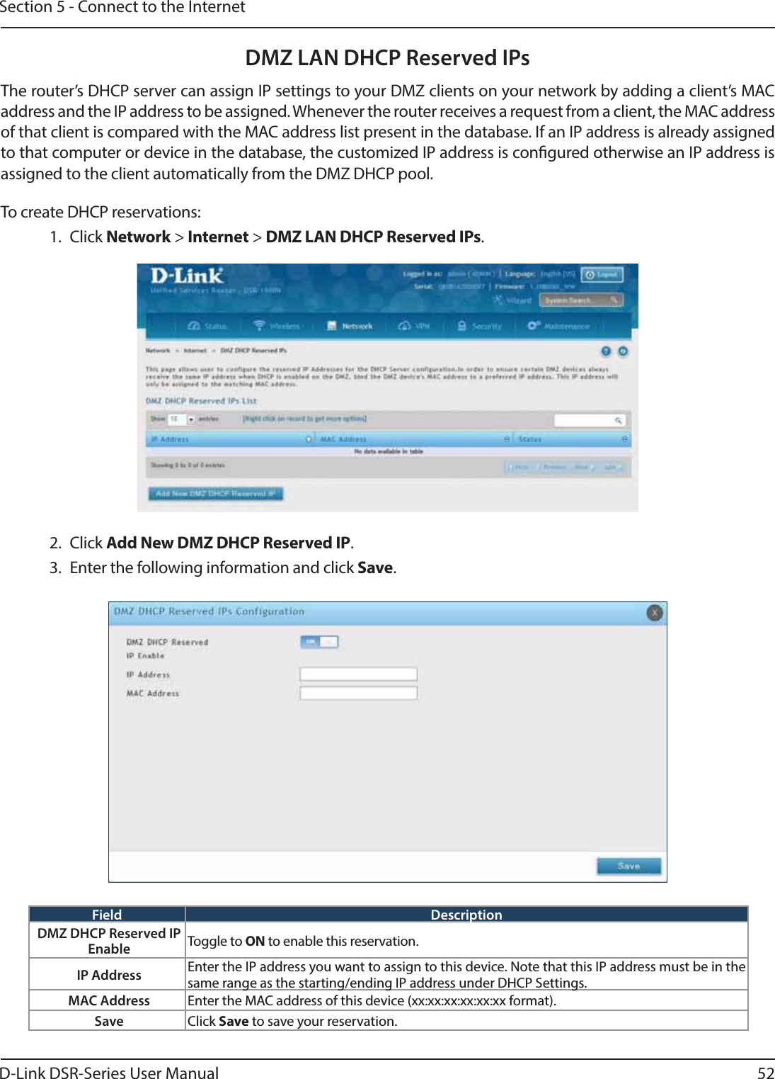
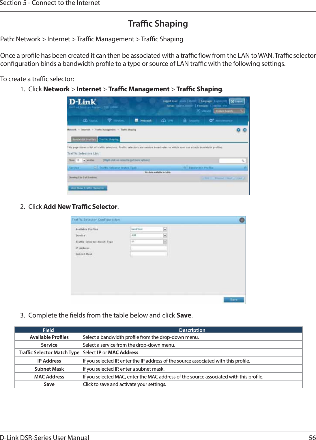
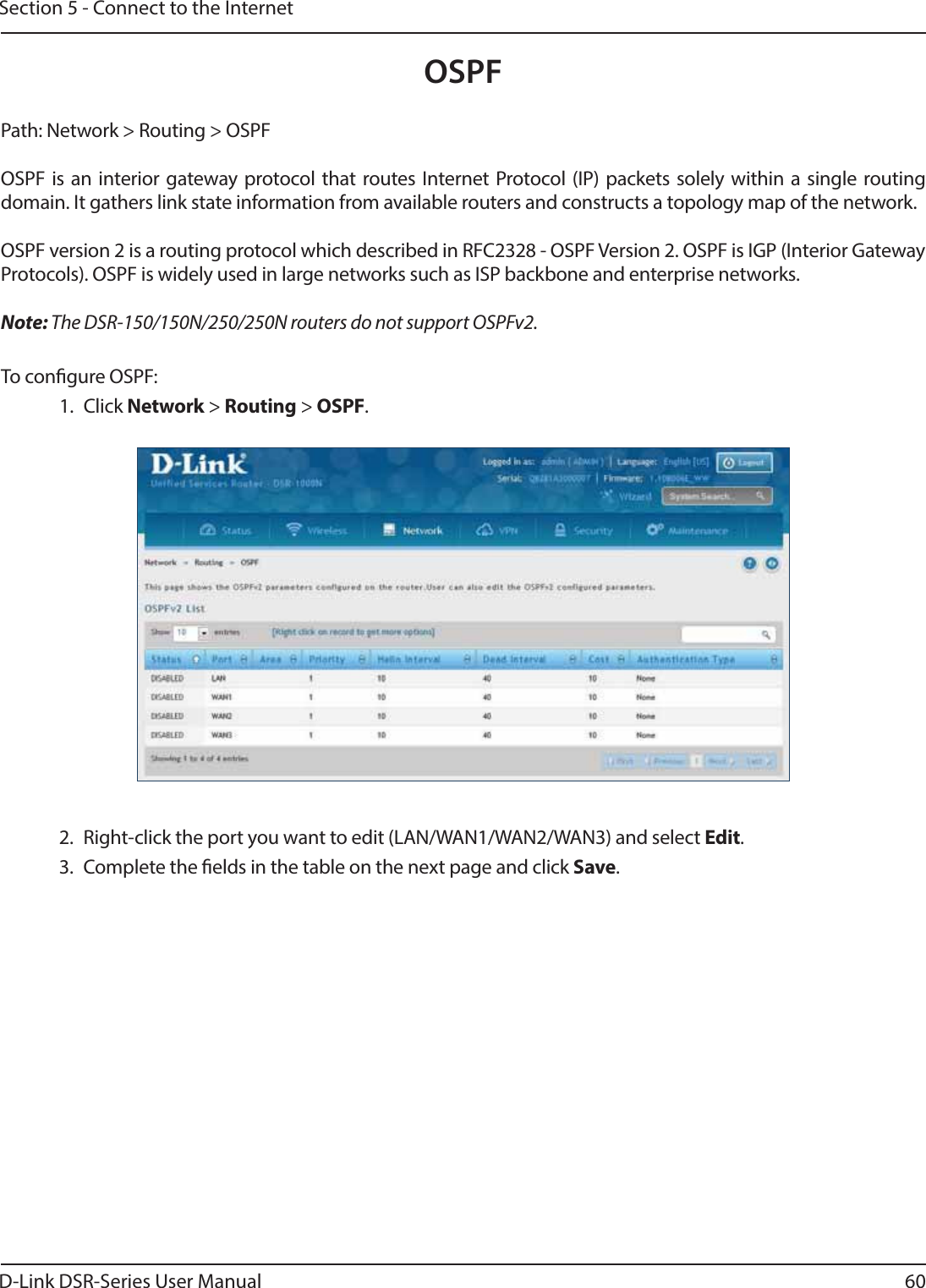
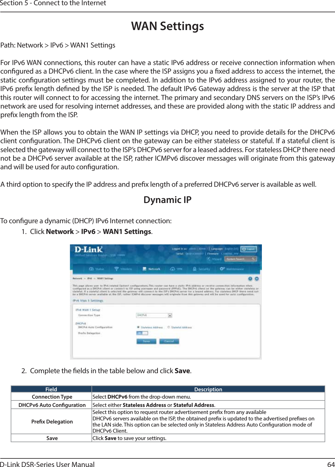
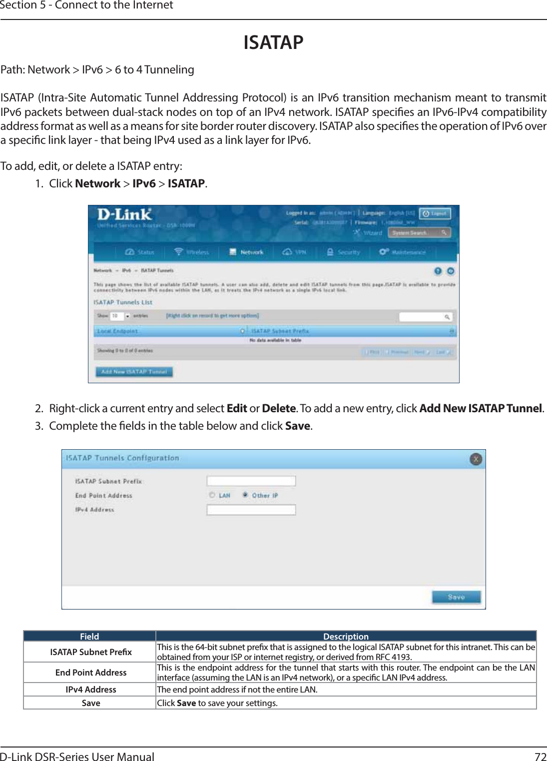
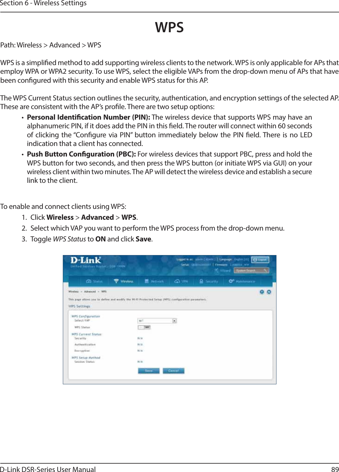
![D-Link DSR-Series User Manual 233Appendix D - Log Output ReferencenimfAdvOptSetWrap: looks like we are reconnecting. “ DEBUG ddns: SQL error: %s ERRORnimfAdvOptSetWrap: Mtu Size: %d DEBUG ddnsDisable failed ERRORnimfAdvOptSetWrap: NIMF table is %s DEBUG ddns: SQL error: %s ERRORnimfAdvOptSetWrap:WAN_MODE TRIGGER DEBUG sqlite3QueryResGet failed.Query:%s ERRORnimfAdvOptSetWrap: MTU: %d DEBUG Failed to call ddns enable ERRORnimfAdvOptSetWrap: MacAddress: %s DEBUG ddns: SQL error: %s ERRORnimfAdvOptSetWrap: old Mtu Flag: %d DEBUG ddnsDisable failed ERRORnimfAdvOptSetWrap: user has changed MTU option DEBUG ddns: SQL error: %s ERRORnimfAdvOptSetWrap: MTU: %d DEBUG sqlite3QueryResGet failed.Query:%s ERRORnimfAdvOptSetWrap: old MTU size: %d DEBUG sqlite3QueryResGet failed.Query:%s ERRORnimfAdvOptSetWrap: old Port Speed Option: %d DEBUG ddnsDisable failed ERRORnimfAdvOptSetWrap: old Mac Address Option: %d DEBUG ddns: SQL error: %s ERRORnimfAdvOptSetWrap: MacAddress: %s DEBUG sqlite3QueryResGet failed.Query:%s ERRORSetting LED [%d]:[%d] For %s DEBUG sqlite3QueryResGet failed.Query:%s ERRORl2tpEnable: command string: %s DEBUG ddnsDisable failed ERRORnimfAdvOptSetWrap: handling reboot scenario DEBUG failed to call ddns enable ERRORnimfAdvOptSetWrap: INDICATOR = %d DEBUG ddns: SQL error: %s ERRORnimfAdvOptSetWrap: UpdateFlag: %d DEBUG ddnsDisable failed ERRORnimfAdvOptSetWrap: returning with status: %s DEBUG sqlite3QueryResGet failed.Query:%s ERRORnimfGetUpdateMacFlag: MacTable Flag is: %d DEBUG Error in executing DB update handler ERRORnimfMacGet: Mac Option changed DEBUG Failed to open the resolv.conf le. Exiting./n ERRORnimfMacGet: Update Flag: %d DEBUG Could not write to the resolv.conf le. Exiting. ERRORnimfMacGet: MacAddress: %s DEBUG Error opening the lanUptime File ERRORnimfMacGet: MacAddress: %s DEBUG Error Opening the lanUptime File. ERRORnimfMacGet: MacAddress: %s DEBUG failed to open %s ERRORnimfMacGet: MacAddress: %s DEBUG failed to open %s ERRORnimfMacGet: MacAddress: %s DEBUG failed to query networkInterface table ERRORnimfMacGet:Mac option Not changed \ DEBUG failed to query networkInterface table ERRORnimfMacGet: MacAddress: %s DEBUG sqlite3QueryResGet failed.Query:%s ERROR](https://usermanual.wiki/D-Link/SR500ACA1/User-Guide-2623752-Page-246.png)
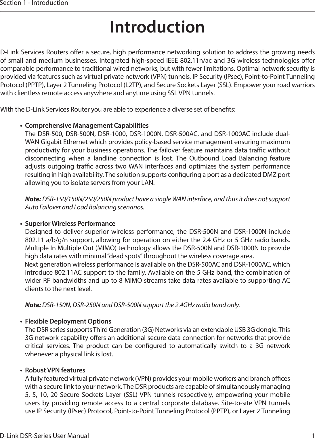
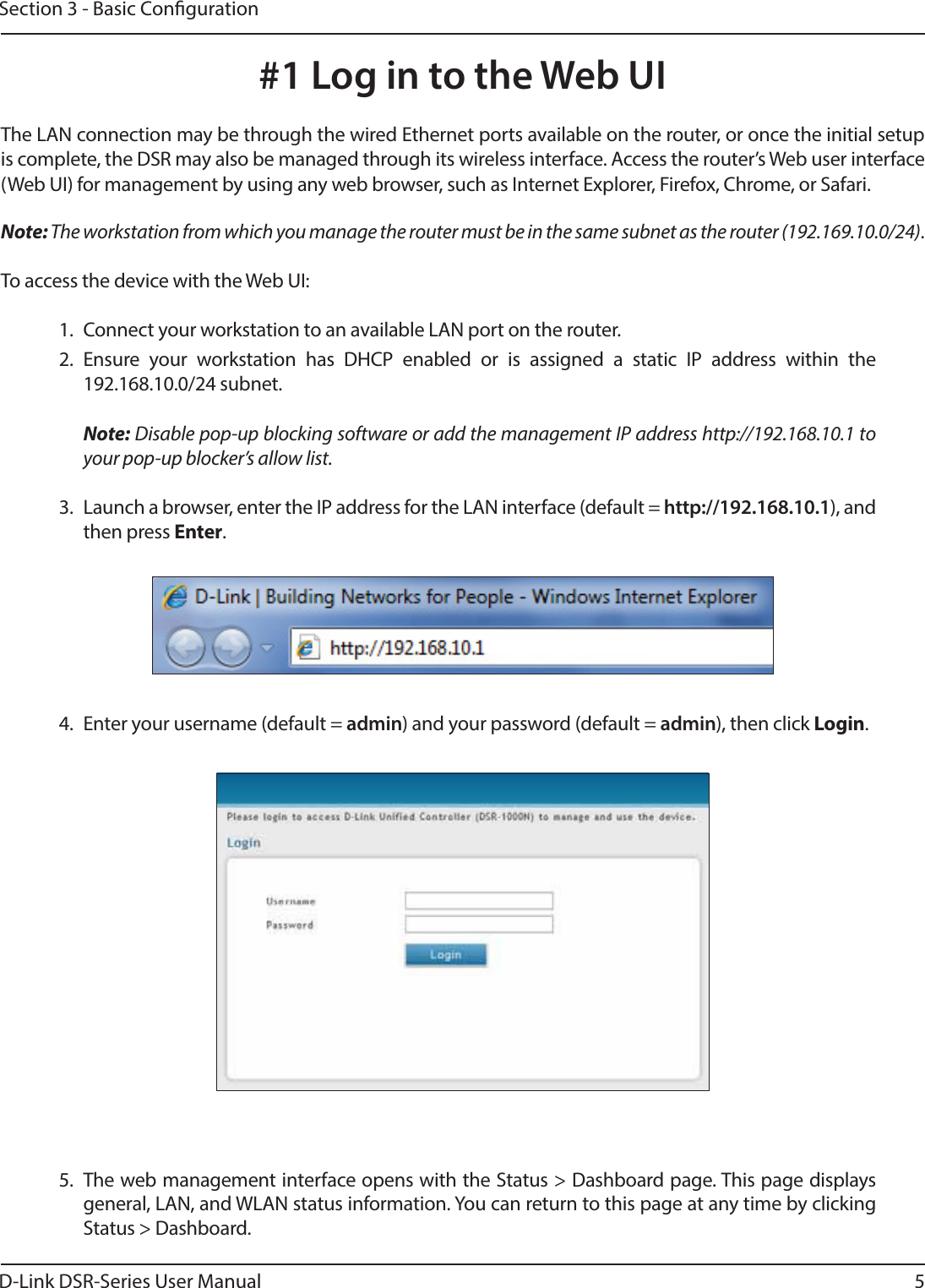
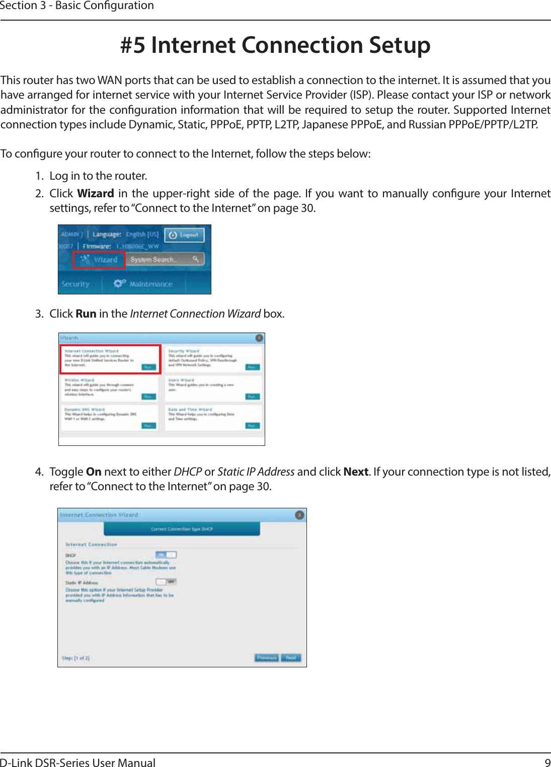
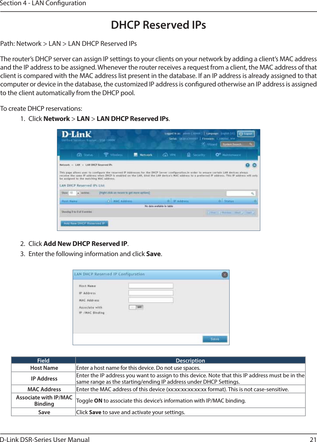
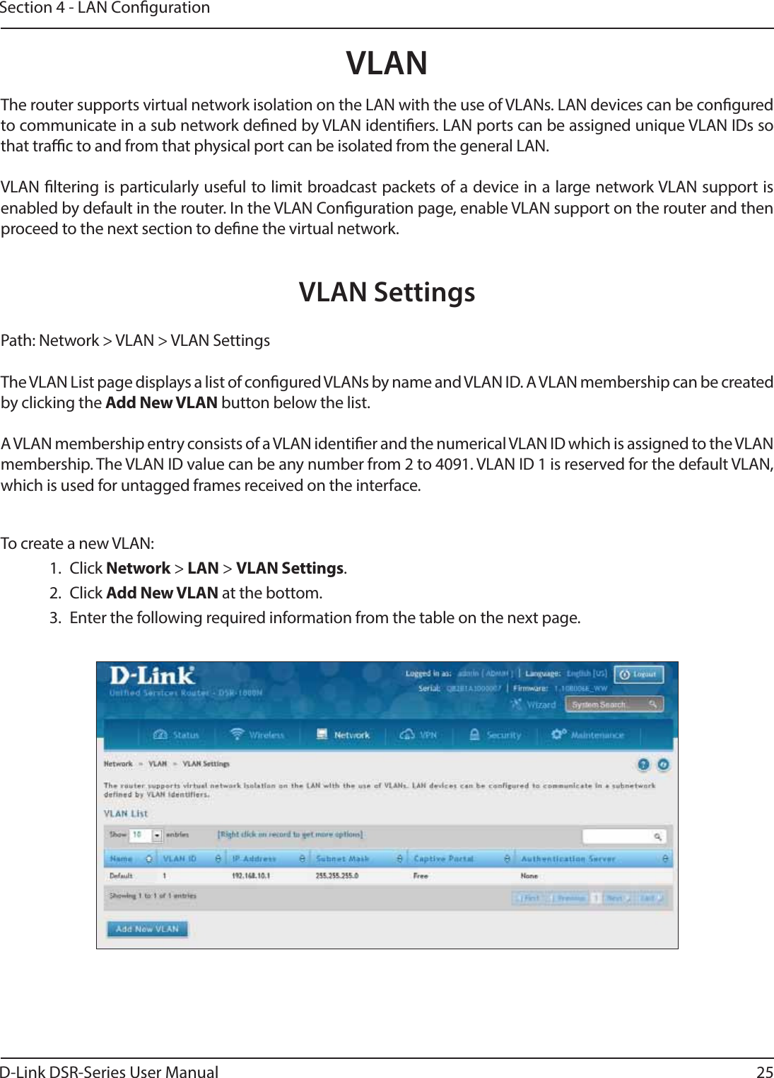
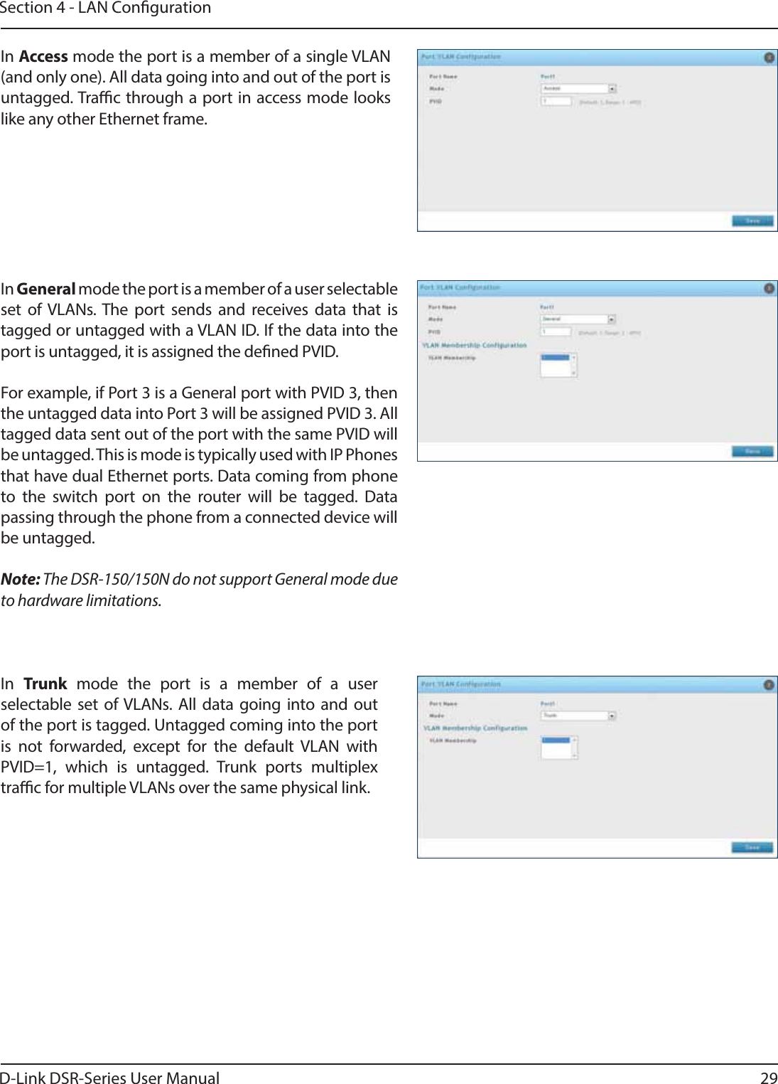
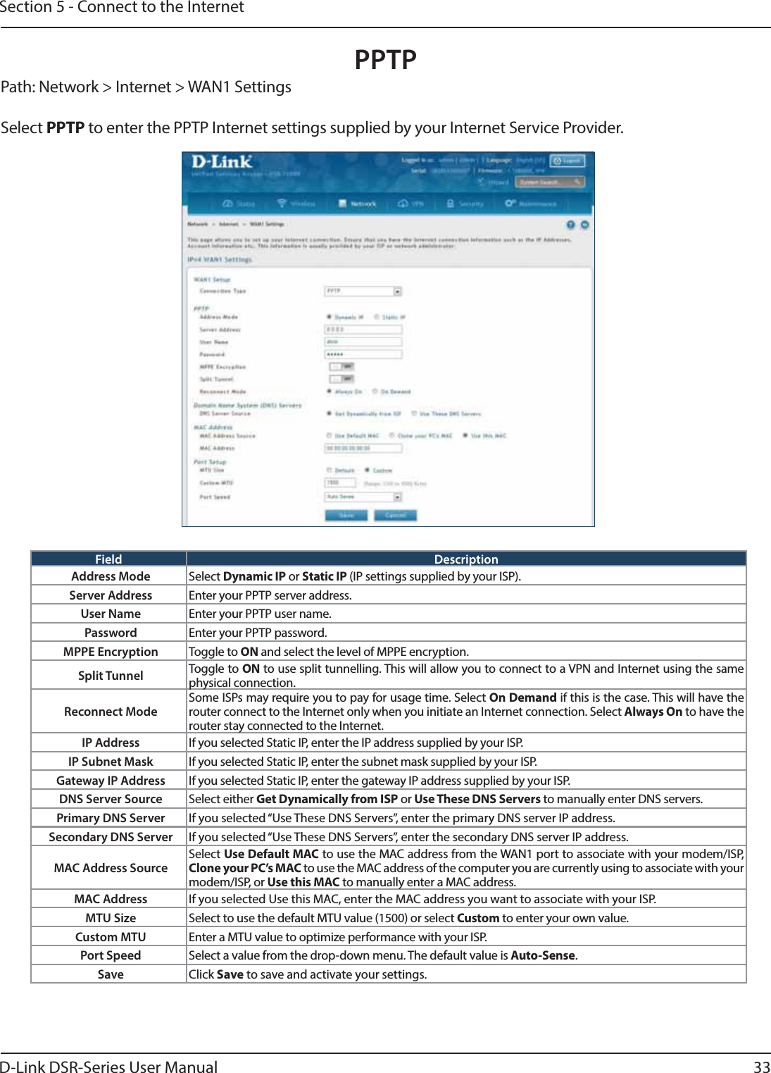
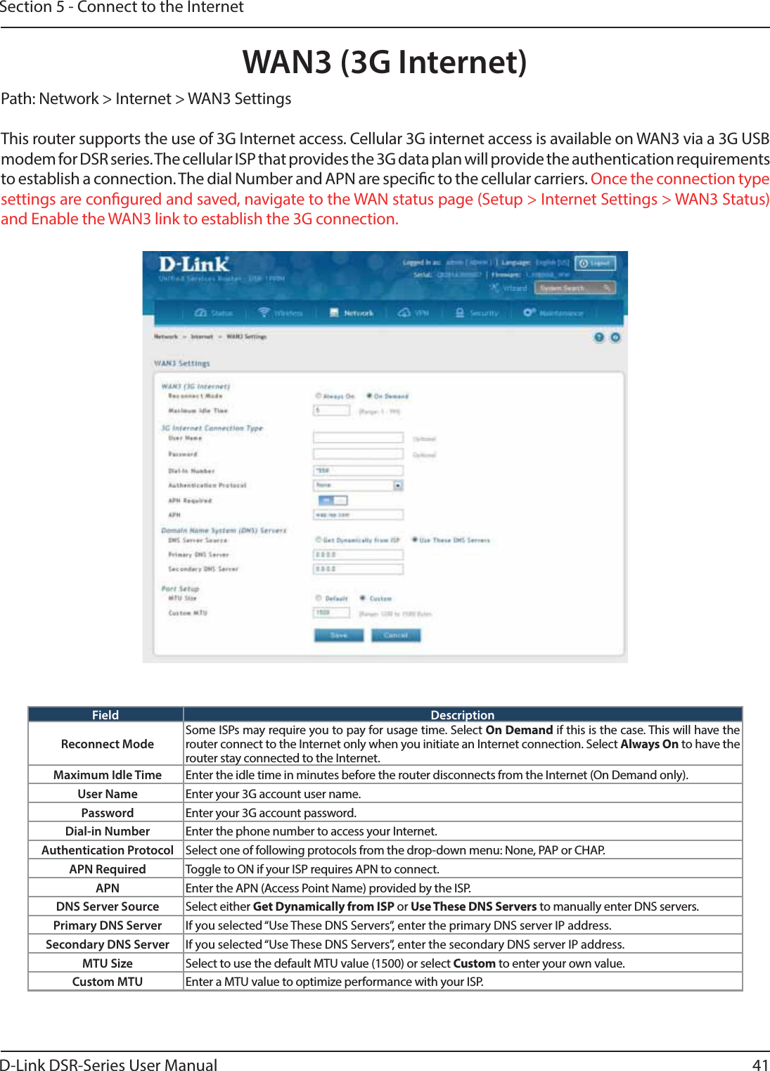
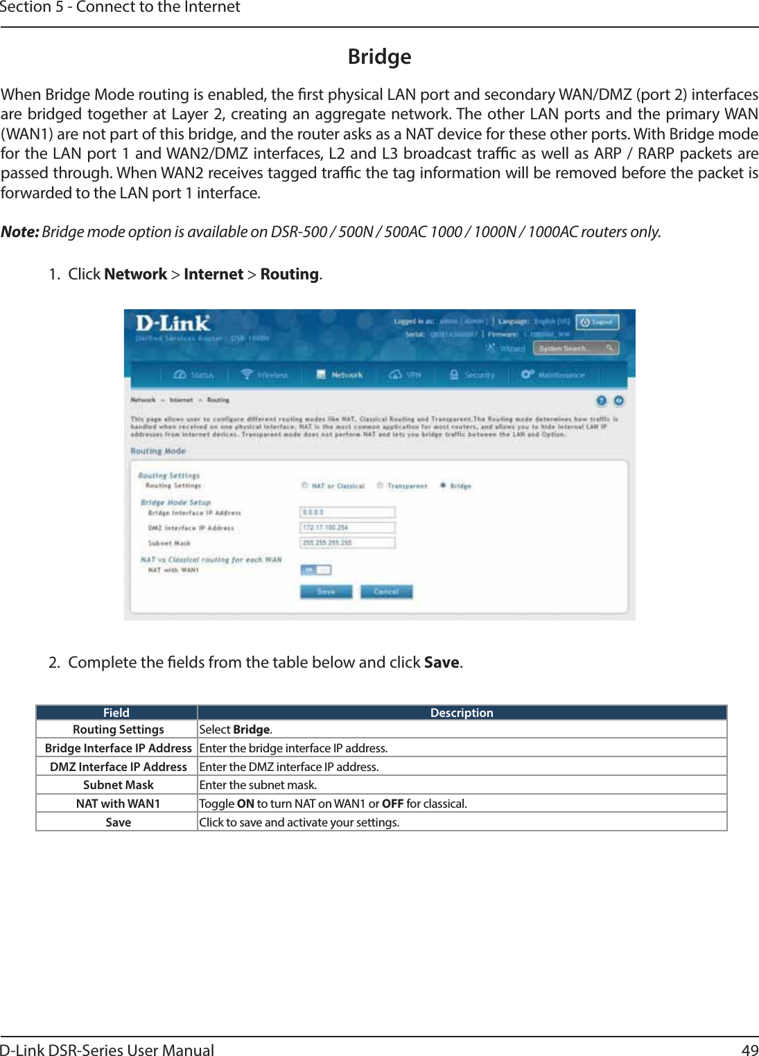
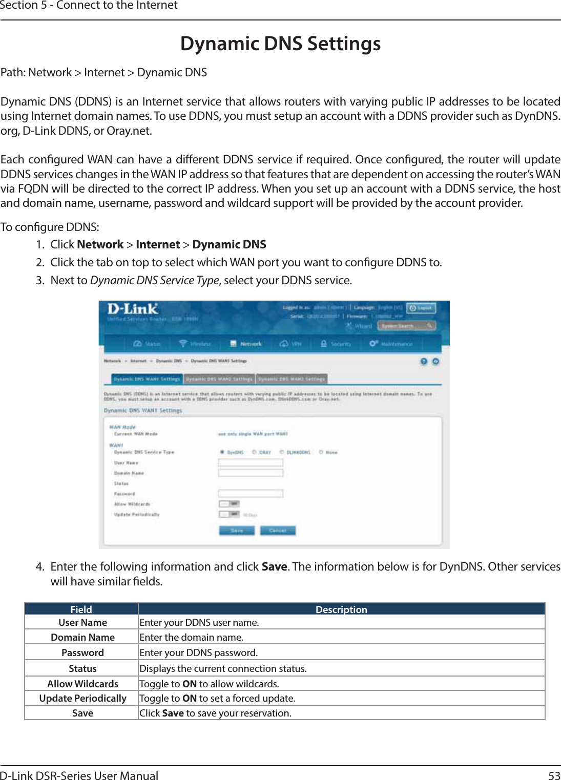
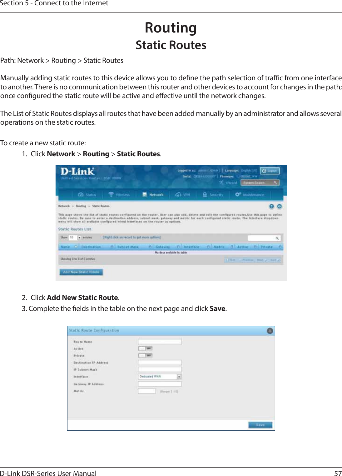
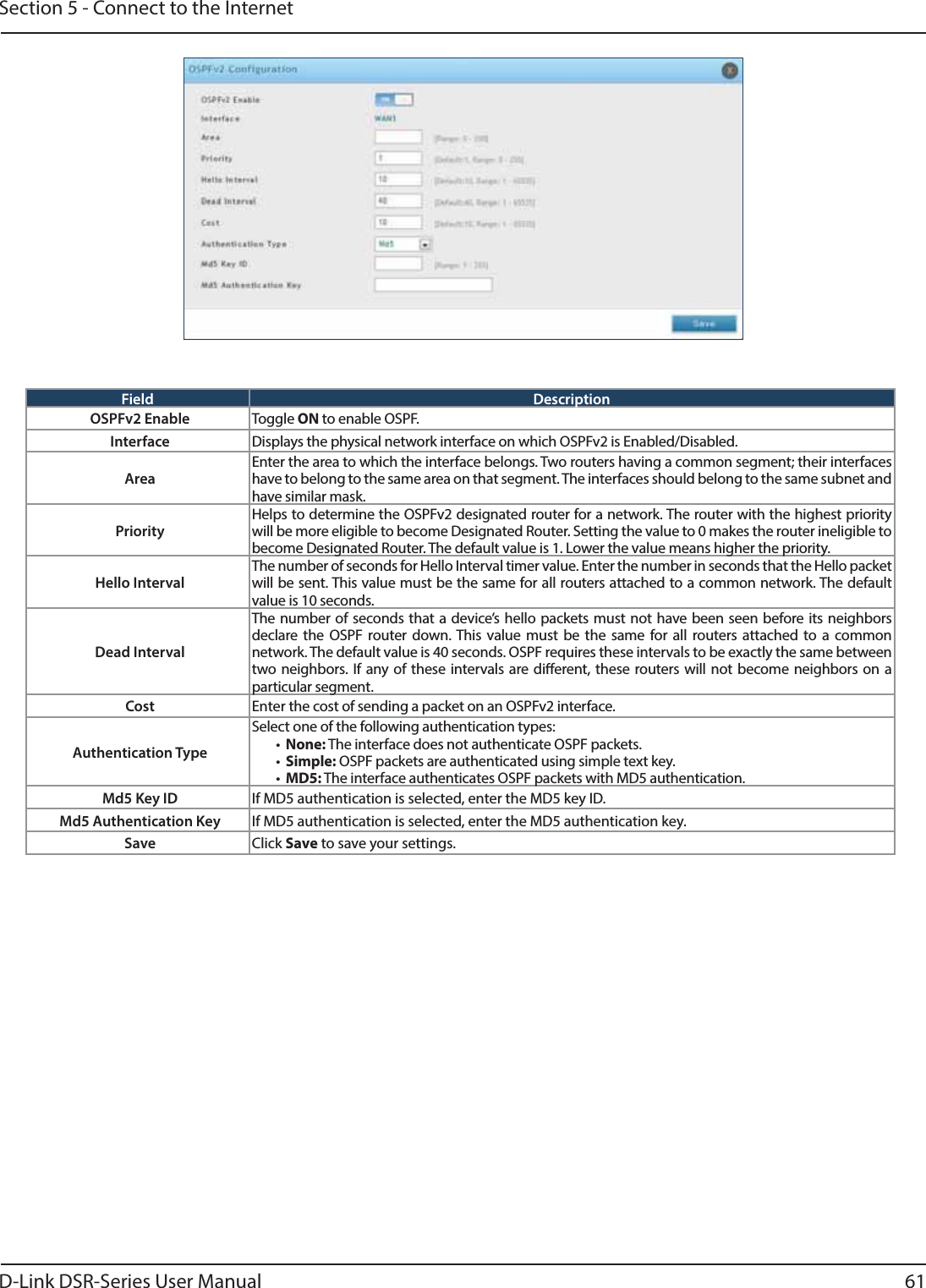
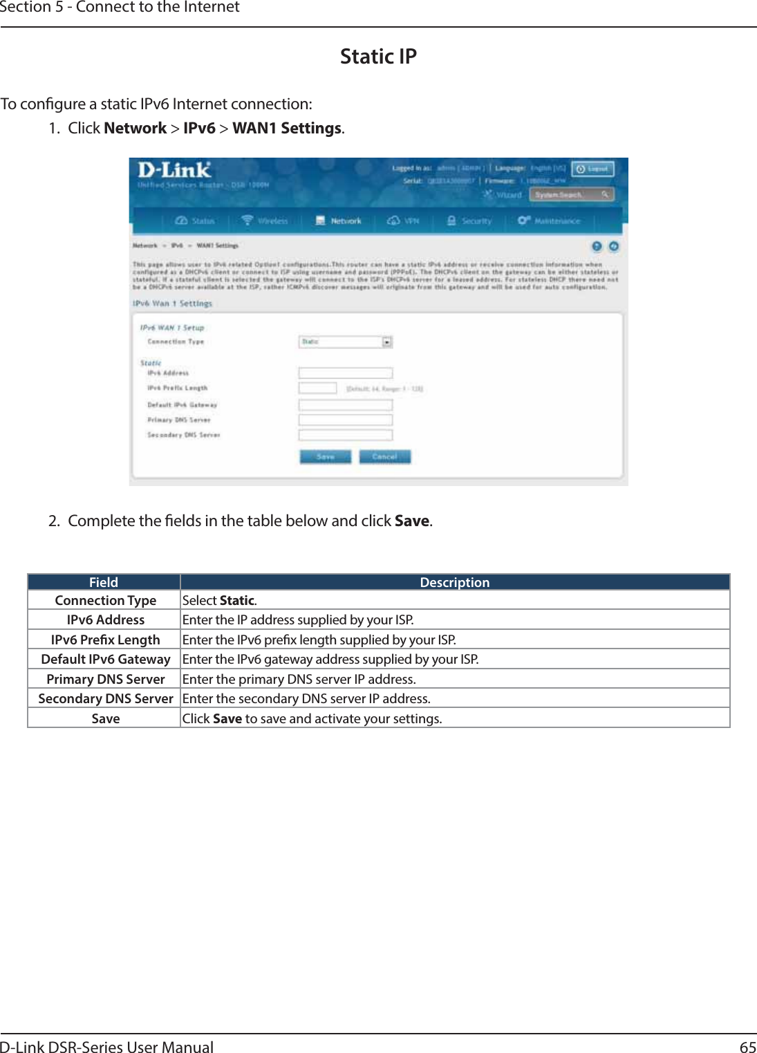
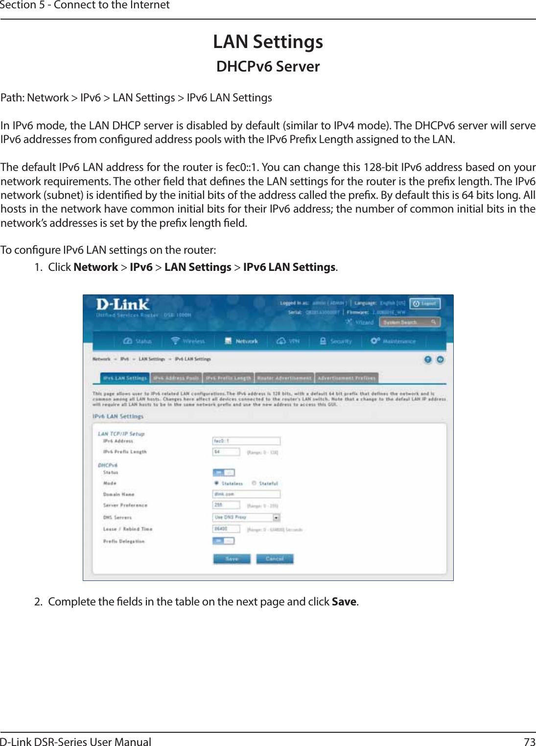
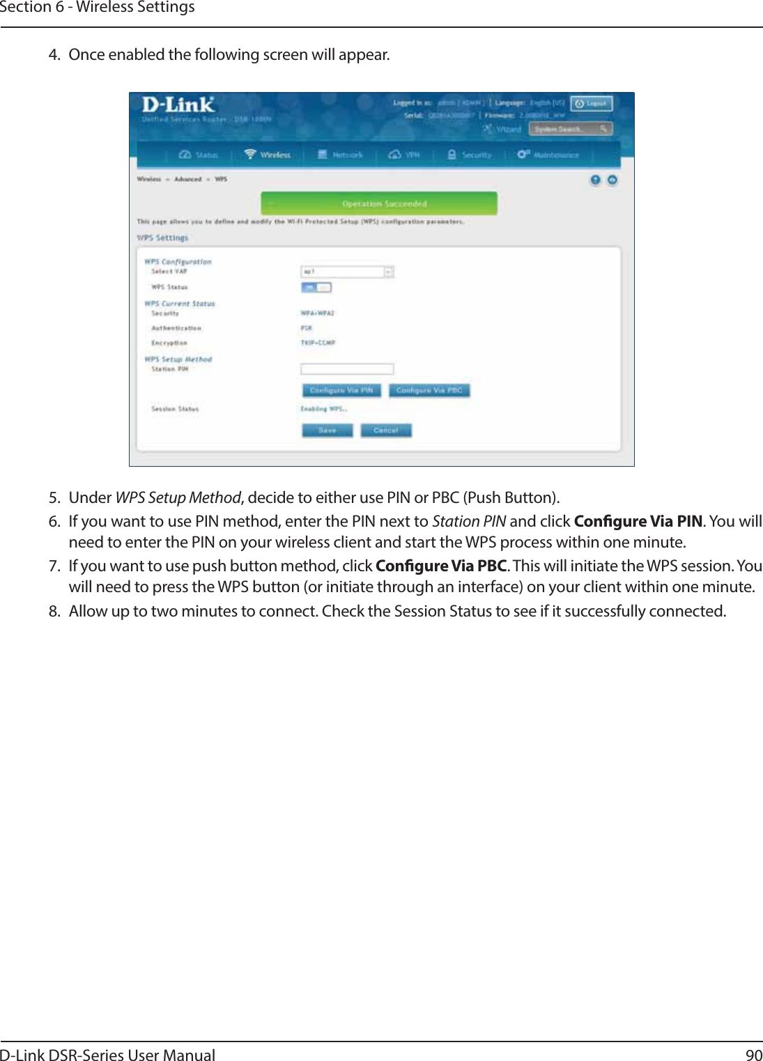
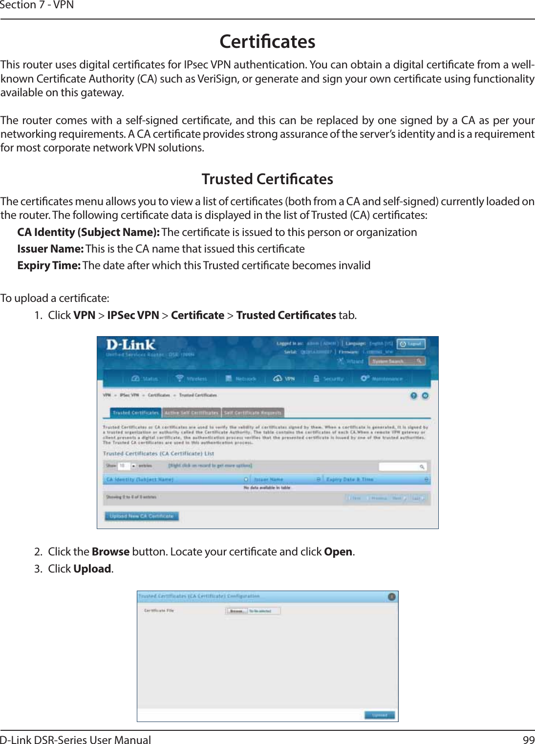
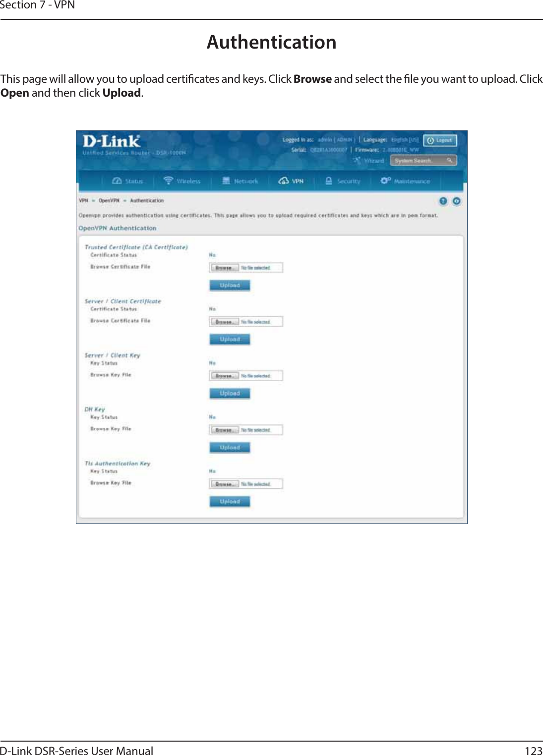
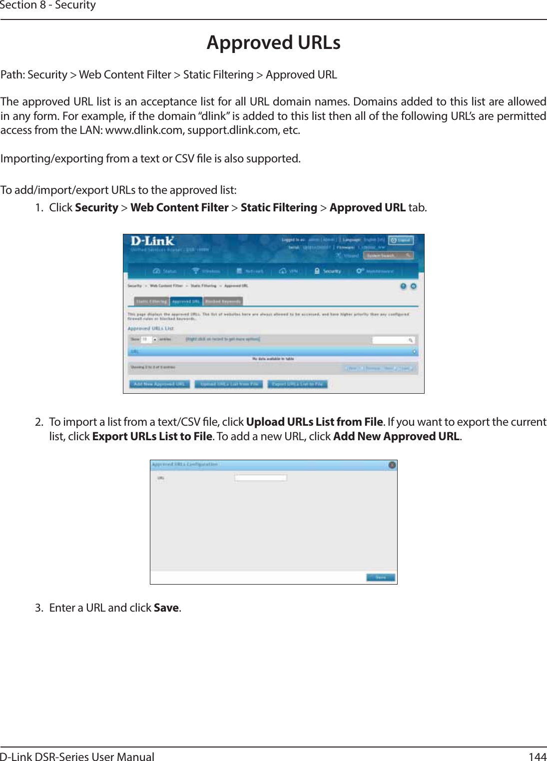
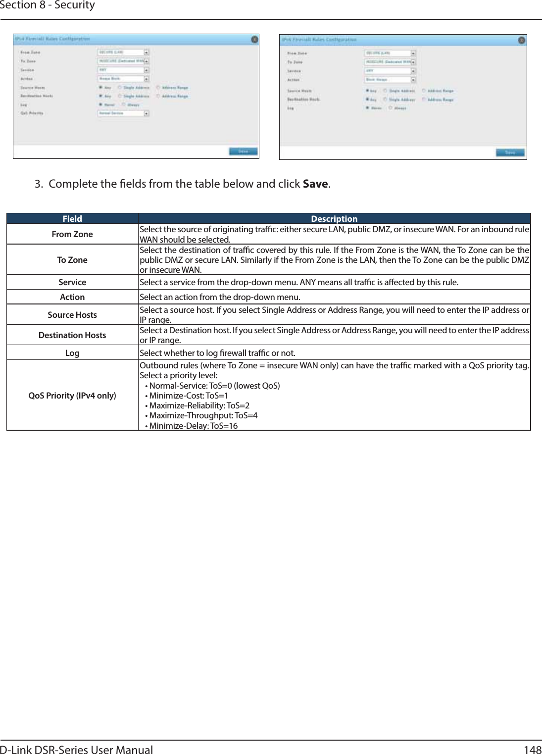
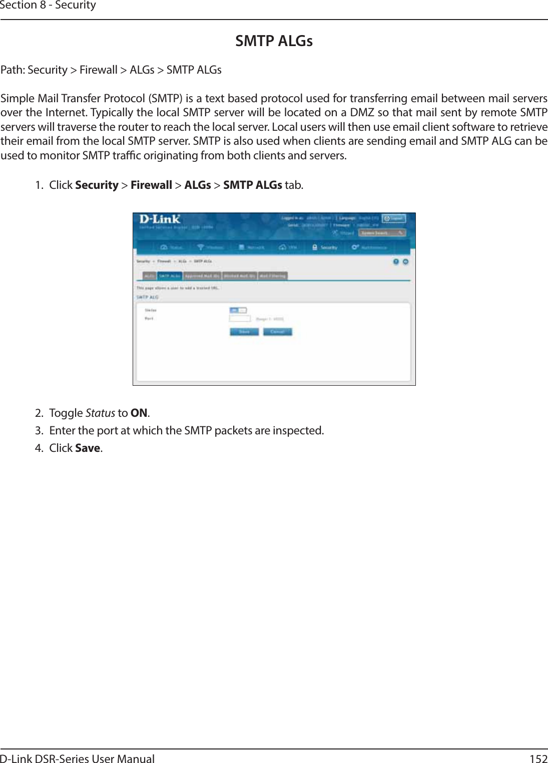
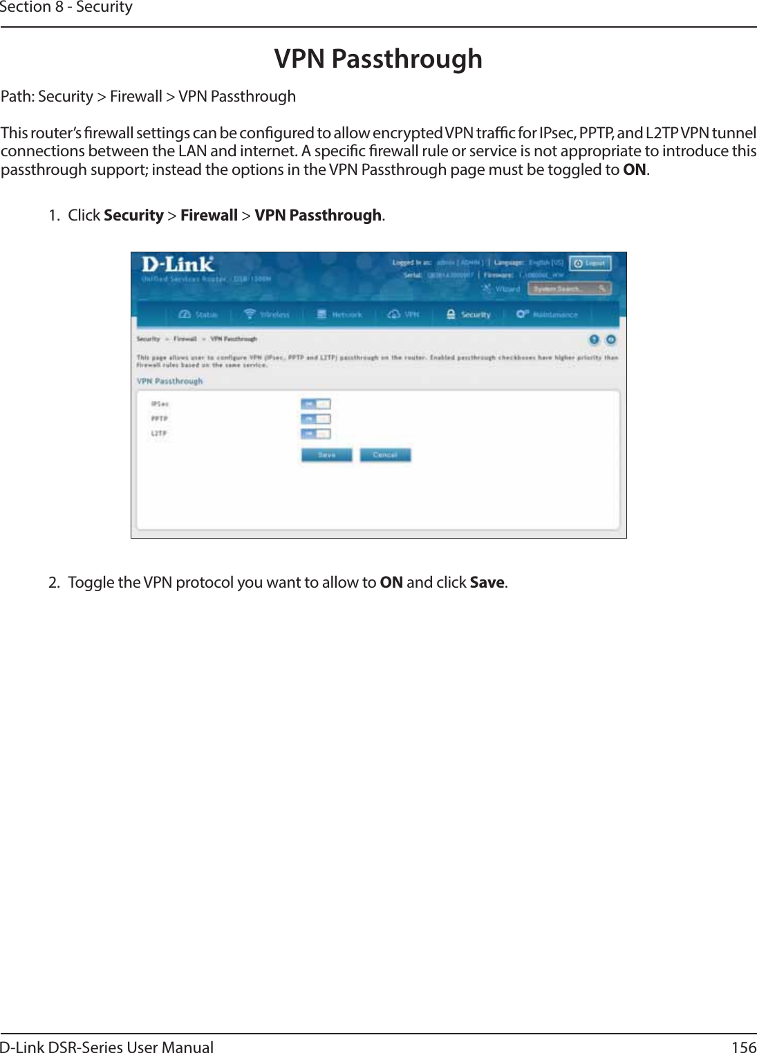
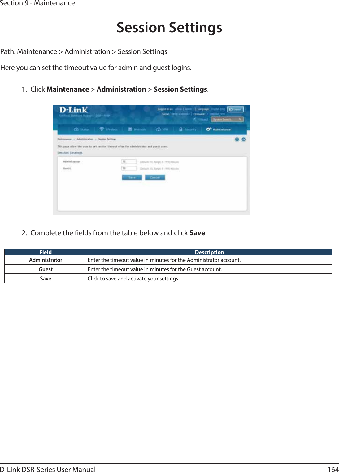
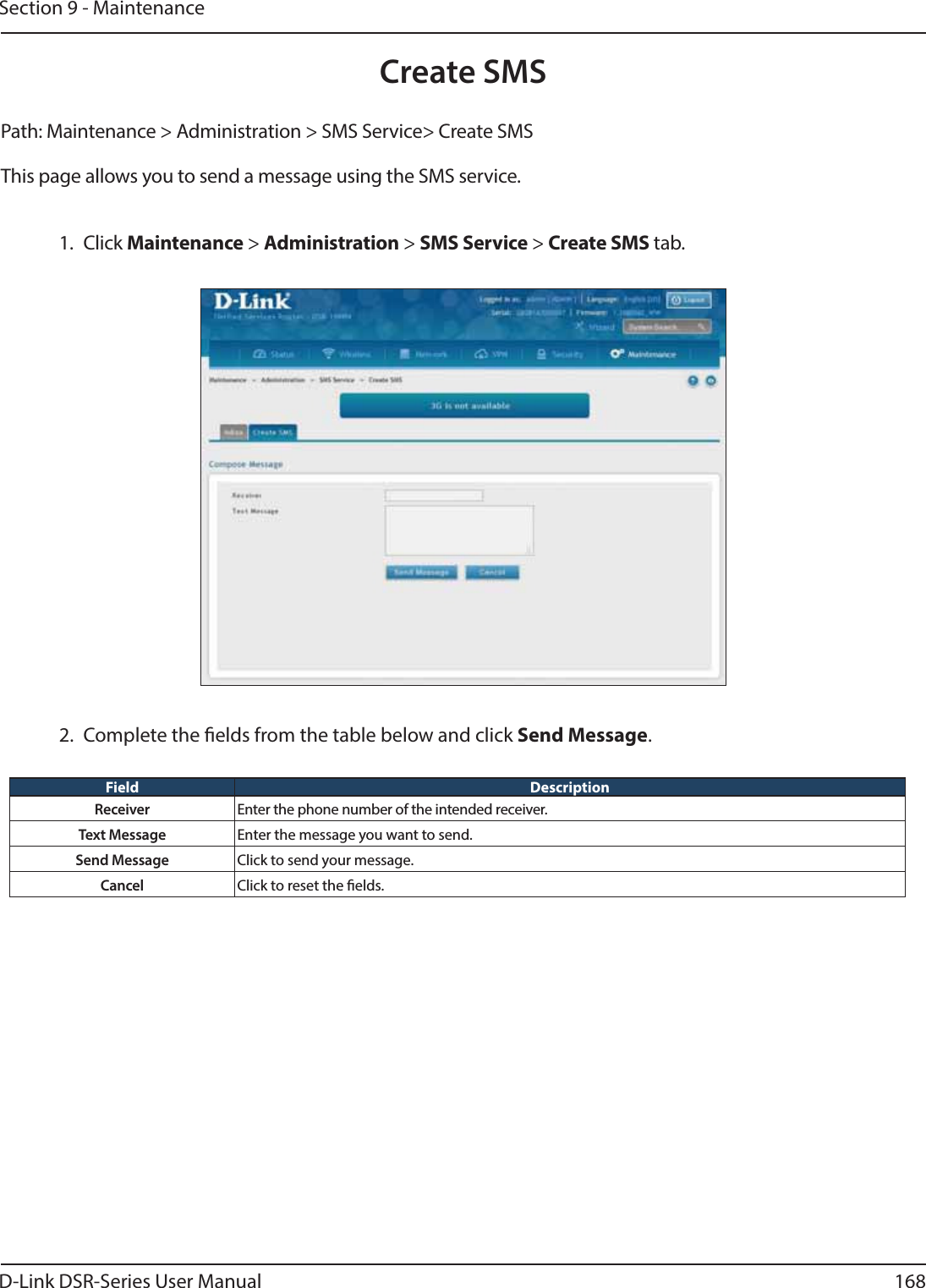
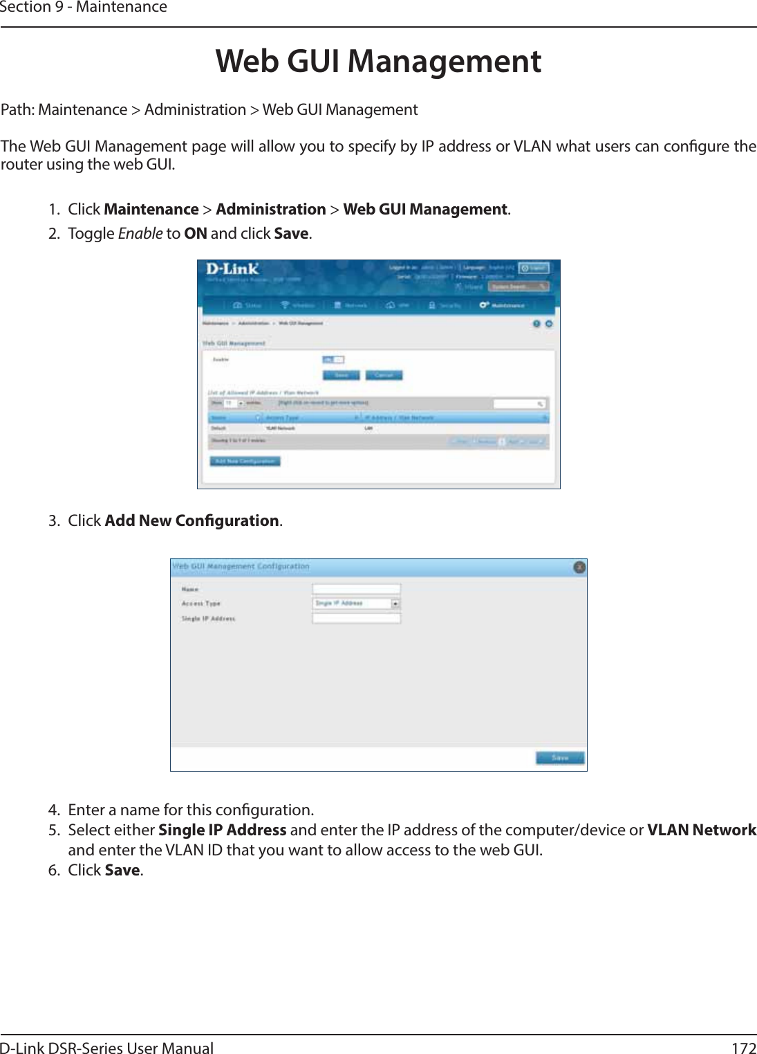
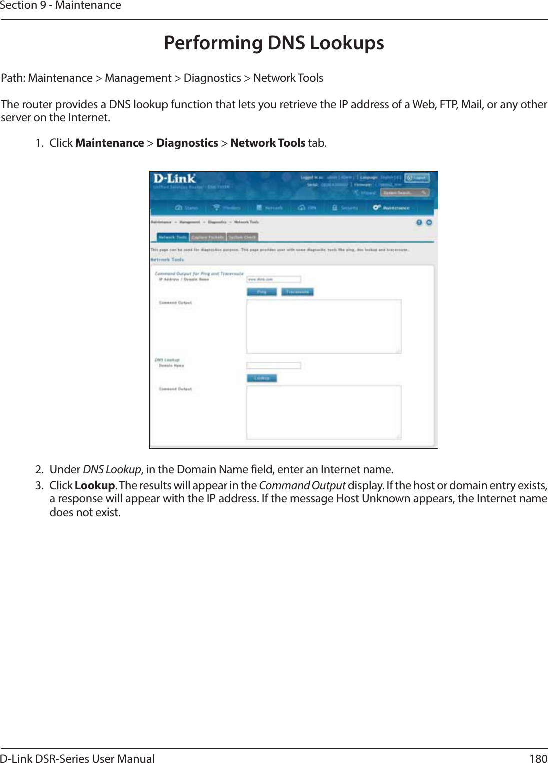
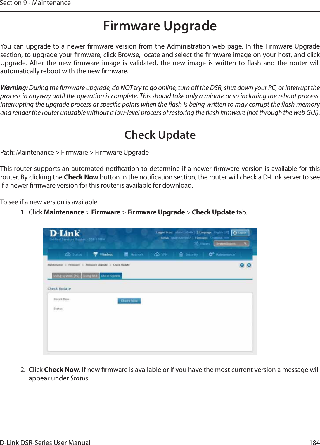
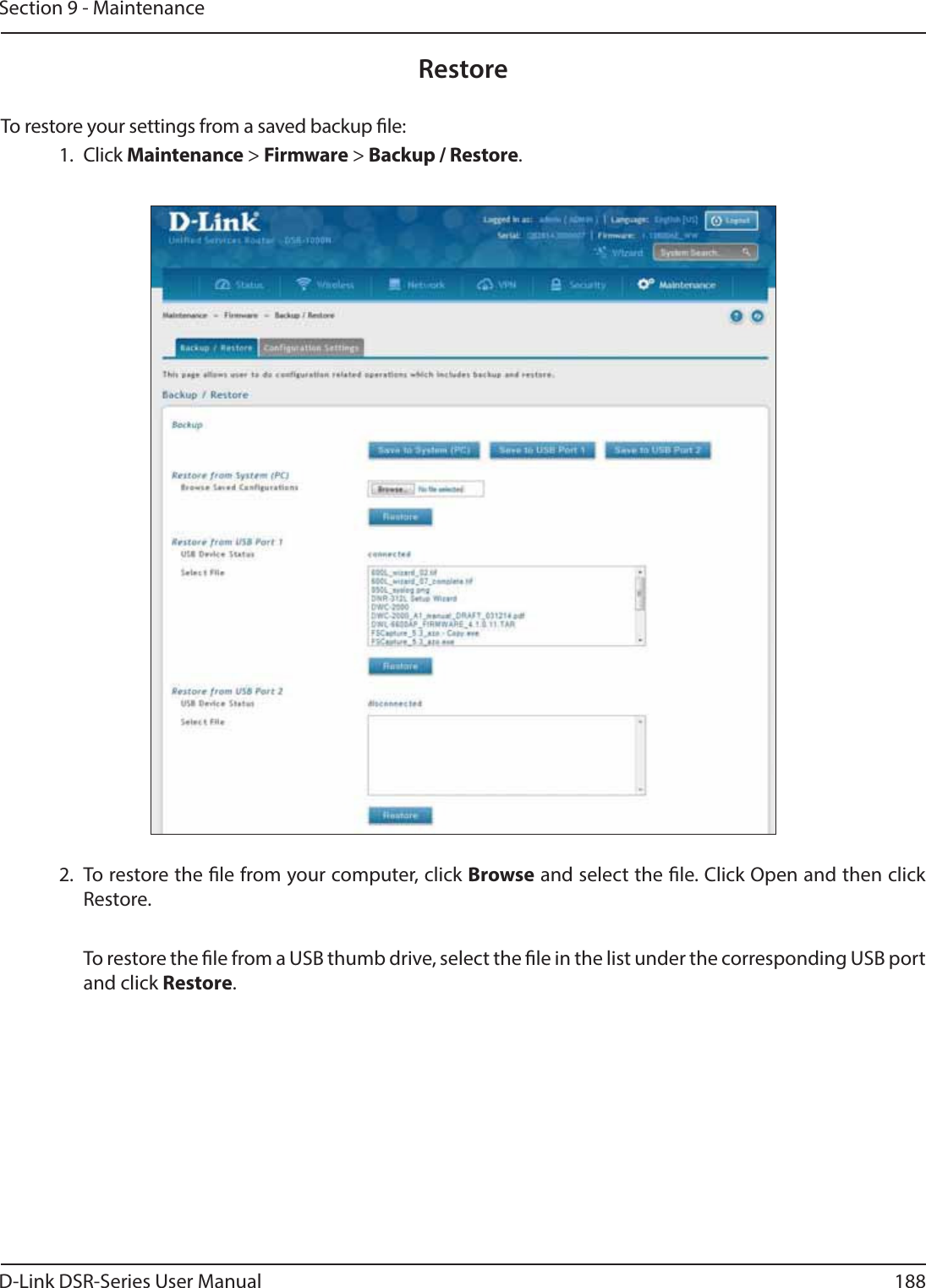
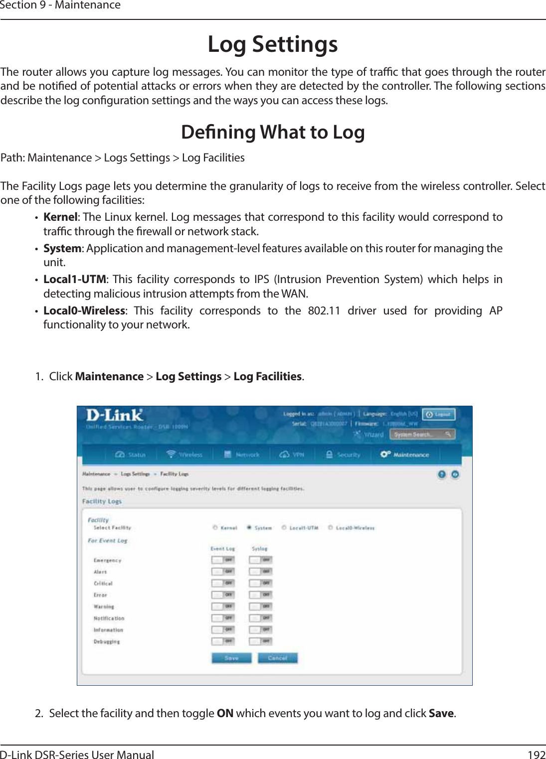
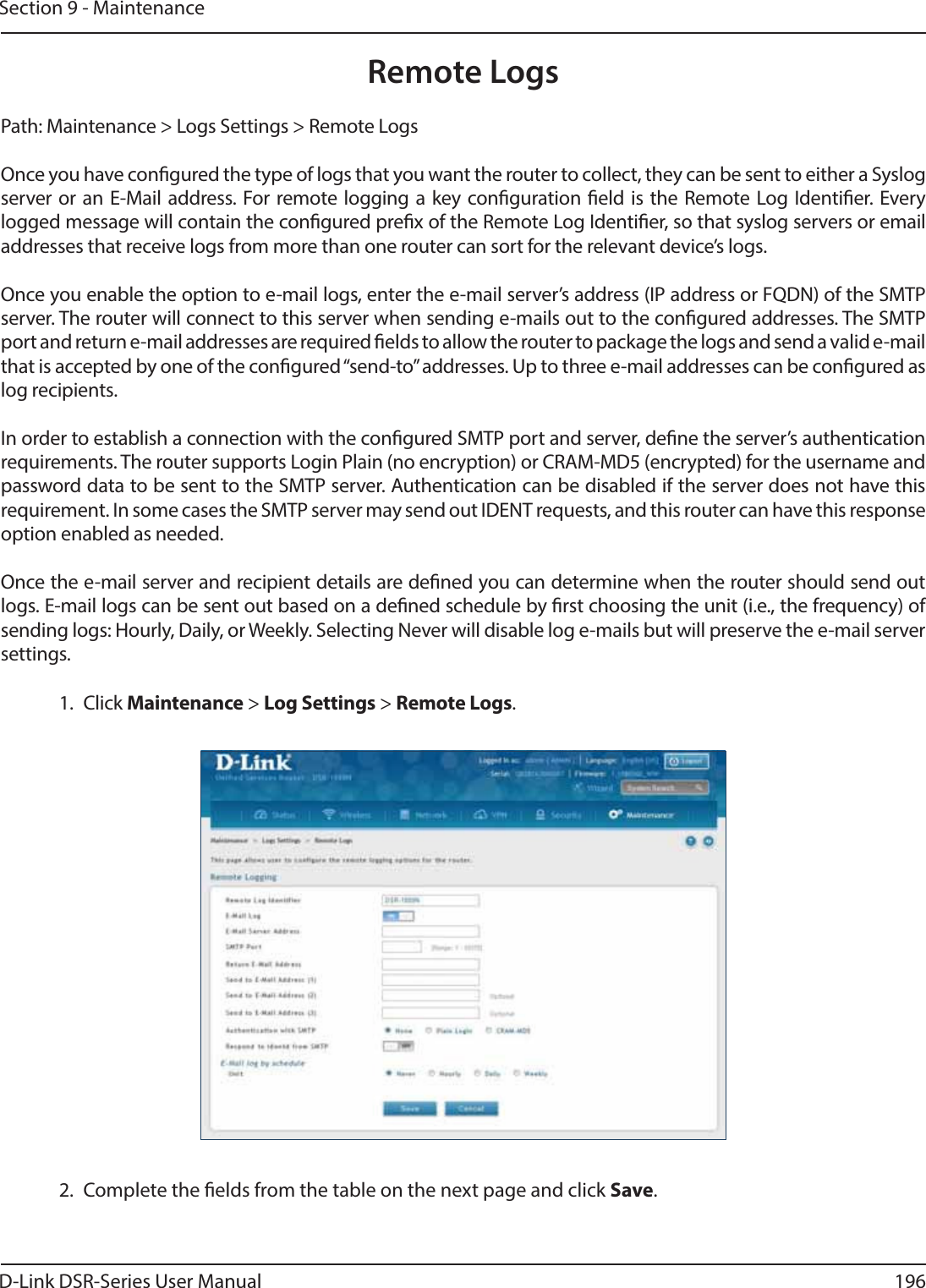
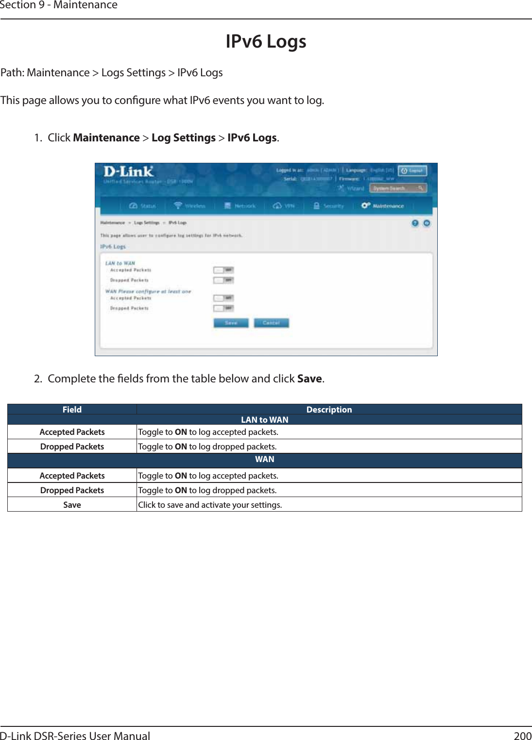
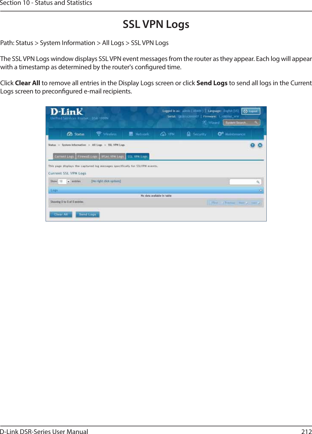
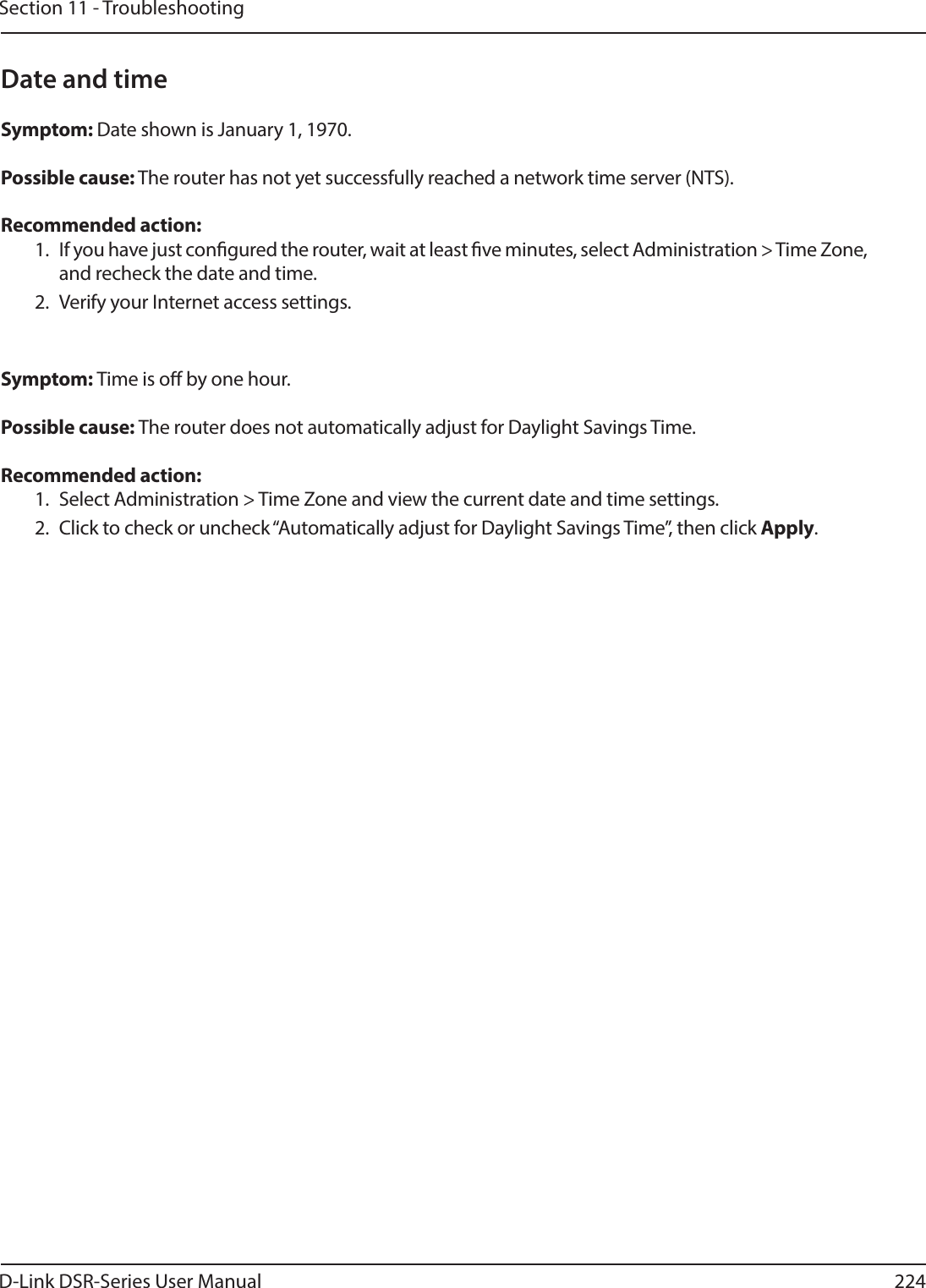
![D-Link DSR-Series User Manual 236Appendix D - Log Output Referencevlan disabled, not applying vlan conguration.. DEBUG disableLan function is failed to disable CongPort” ERRORfailed query %s DEBUG sqlite3QueryResGet failed.Query:%s ERRORfailed query %s DEBUG sqlite3QueryResGet failed.Query:%s ERRORno ports present in this vlanId %d DEBUG Unable to Disable congurable port from ERRORfailed query %s DEBUG congPortTblHandler has failed ERRORvlan disabled, not applying vlan conguration.. DEBUG sqlite3QueryResGet failed.Query:%s ERRORdisabling vlan DEBUG Error in executing DB update handler ERRORenabling vlan DEBUG sqlite3QueryResGet failed ERRORvlan disabled, not applying vlan conguration.. DEBUG Failed to execute switchCong for port\ ERRORno ports present in this vlanId %d DEBUG Failed to execute switchCong for port enable ERRORfailed query %s DEBUG Failed to execute ifcong for port enable ERRORvlan disabled, not applying vlan conguration.. DEBUG Failed to execute ethtool for\ ERRORremoving %s from bridge%s... %s DEBUG Failed to execute switchCong for port disable ERRORadding %s to bridge%d... %s DEBUG Failed to execute ifcong for port disable ERRORrestarting bridge... DEBUG sqlite3QueryResGet failed ERROR[switchCong] Ignoring event on port number %d DEBUG sqlite3_mprintf failed ERRORrestarting bridge... DEBUG sqlite3QueryResGet failed ERRORexecuting %s ... %s DEBUG Failed to execute switchCong for port mirroring ERRORremoving %s from bridge%s... %s DEBUG Usage:%s <DB Name> <Entry Name> <logFile> <subject> ERRORadding %s to bridge%d... %s DEBUG sqlite3QueryResGet failed ERROR[switchCong] Ignoring event on %s DEBUG Could not get all the required variables to email the Logs. ERRORrestarting bridge... DEBUG runSmtpClient failed ERROR[switchCong] Ignoring event on port number %d DEBUG getaddrinfo returned %s ERROR[switchCong] executing %s ... %s DEBUG le not found ERRORrestarting bridge... DEBUG sqlite3QueryResGet failed.Query:%s ERRORUserName: %s DEBUG sqlite3QueryResGet failed.Query:%s ERRORPassword: %s DEBUG sqlite3QueryResGet failed.Query:%s ERRORIspName: %s DEBUG No memory to allocate ERROR](https://usermanual.wiki/D-Link/SR500ACA1/User-Guide-2623752-Page-249.png)
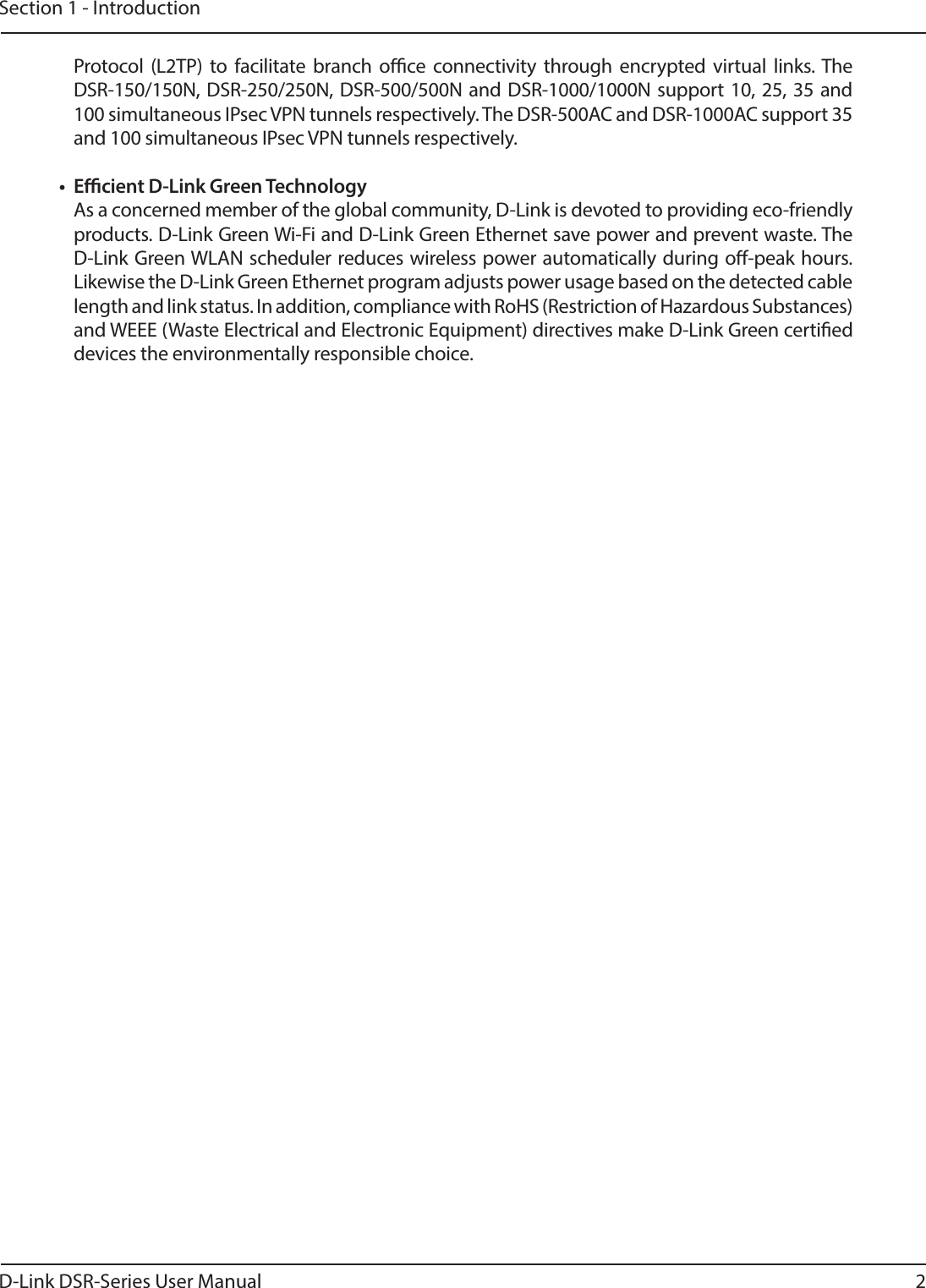
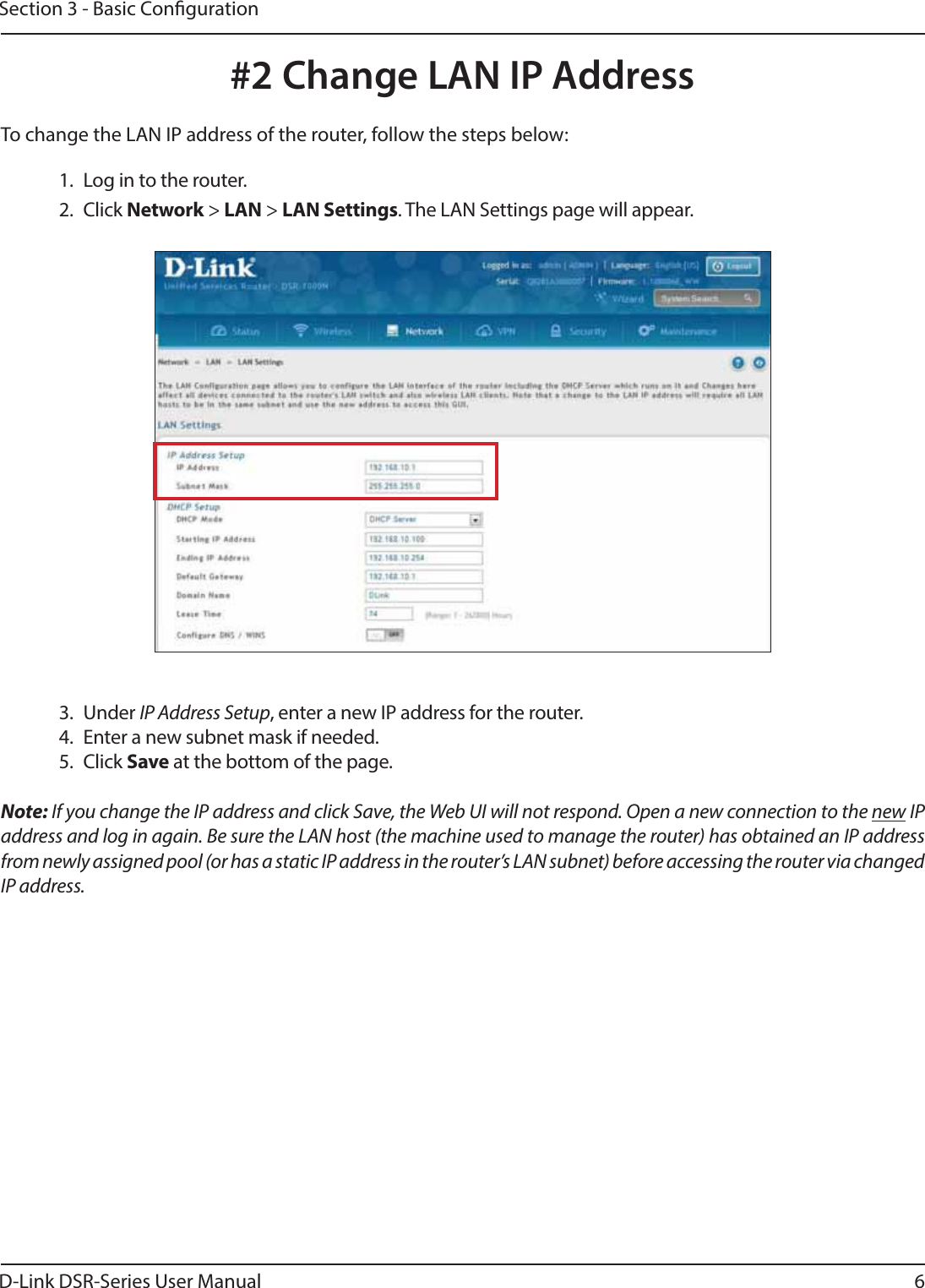
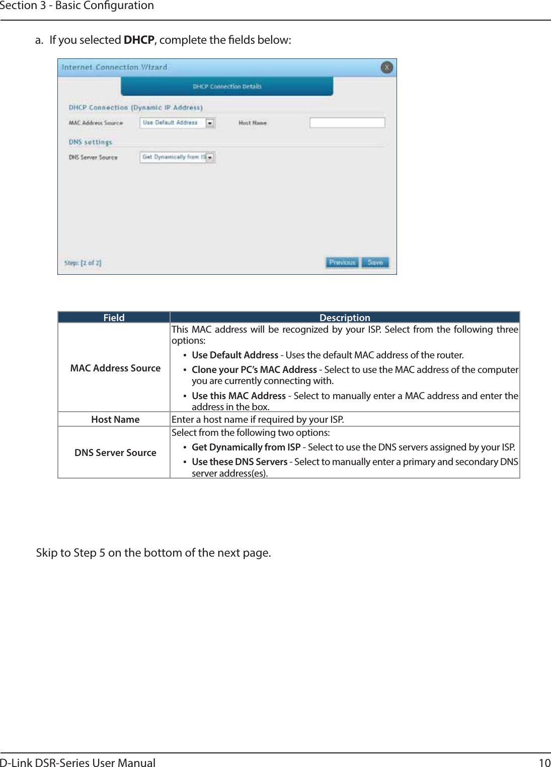
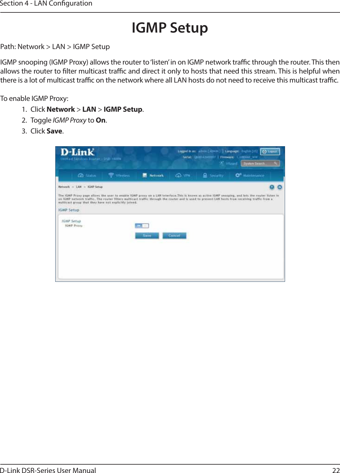
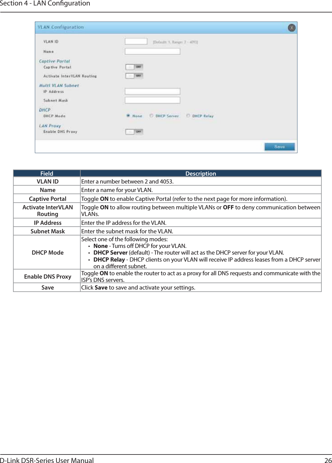
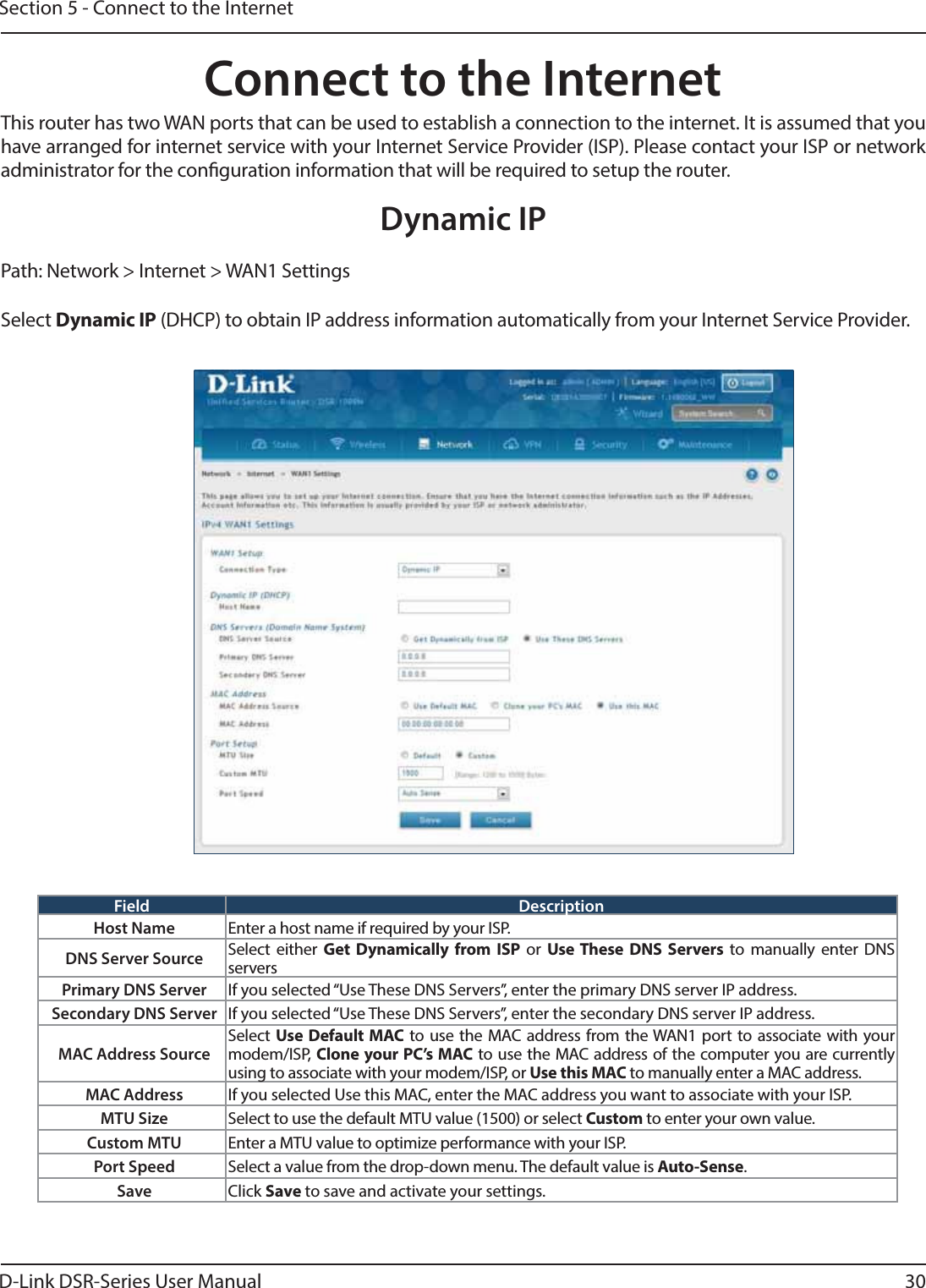
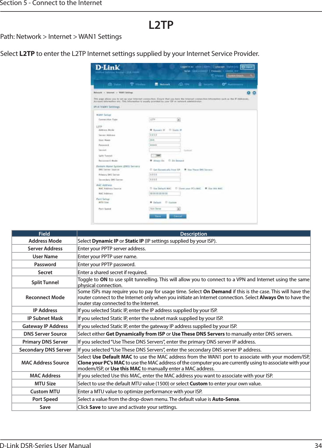
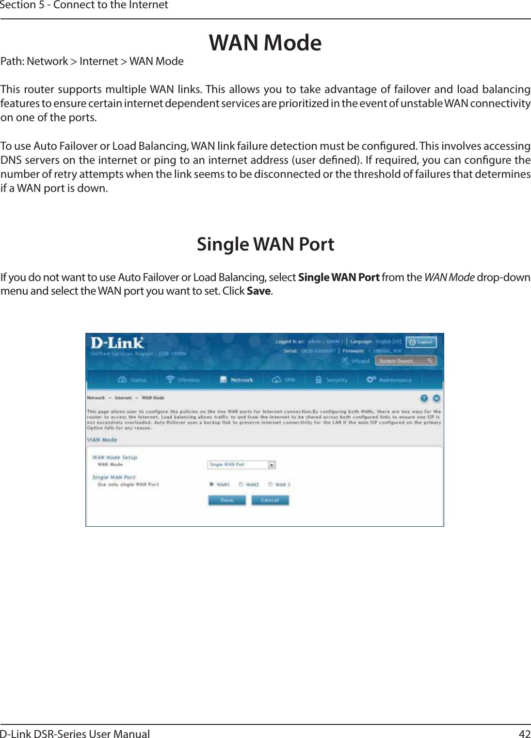
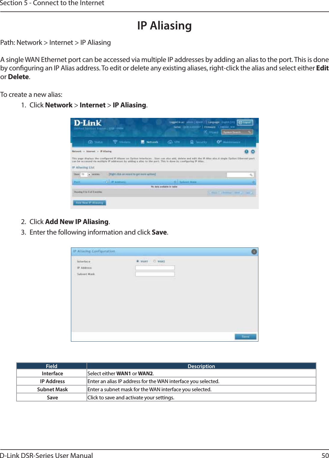
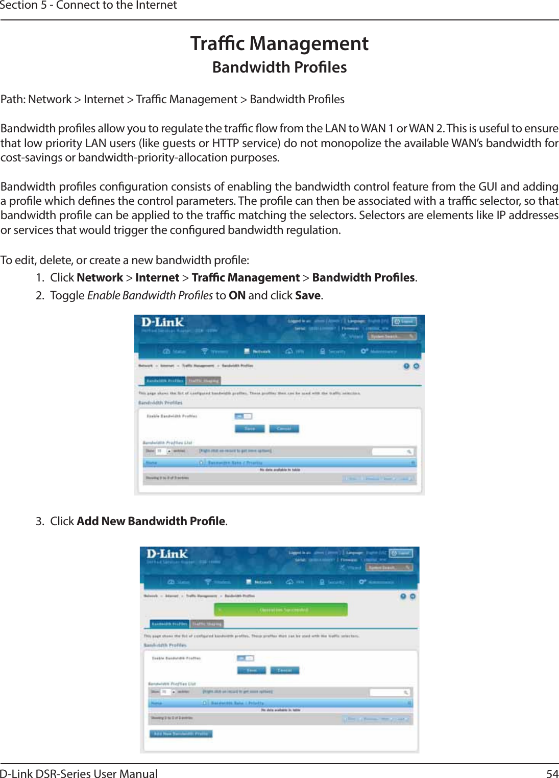
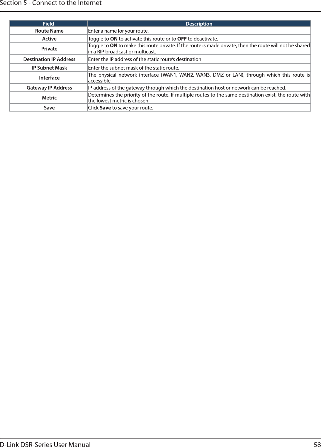
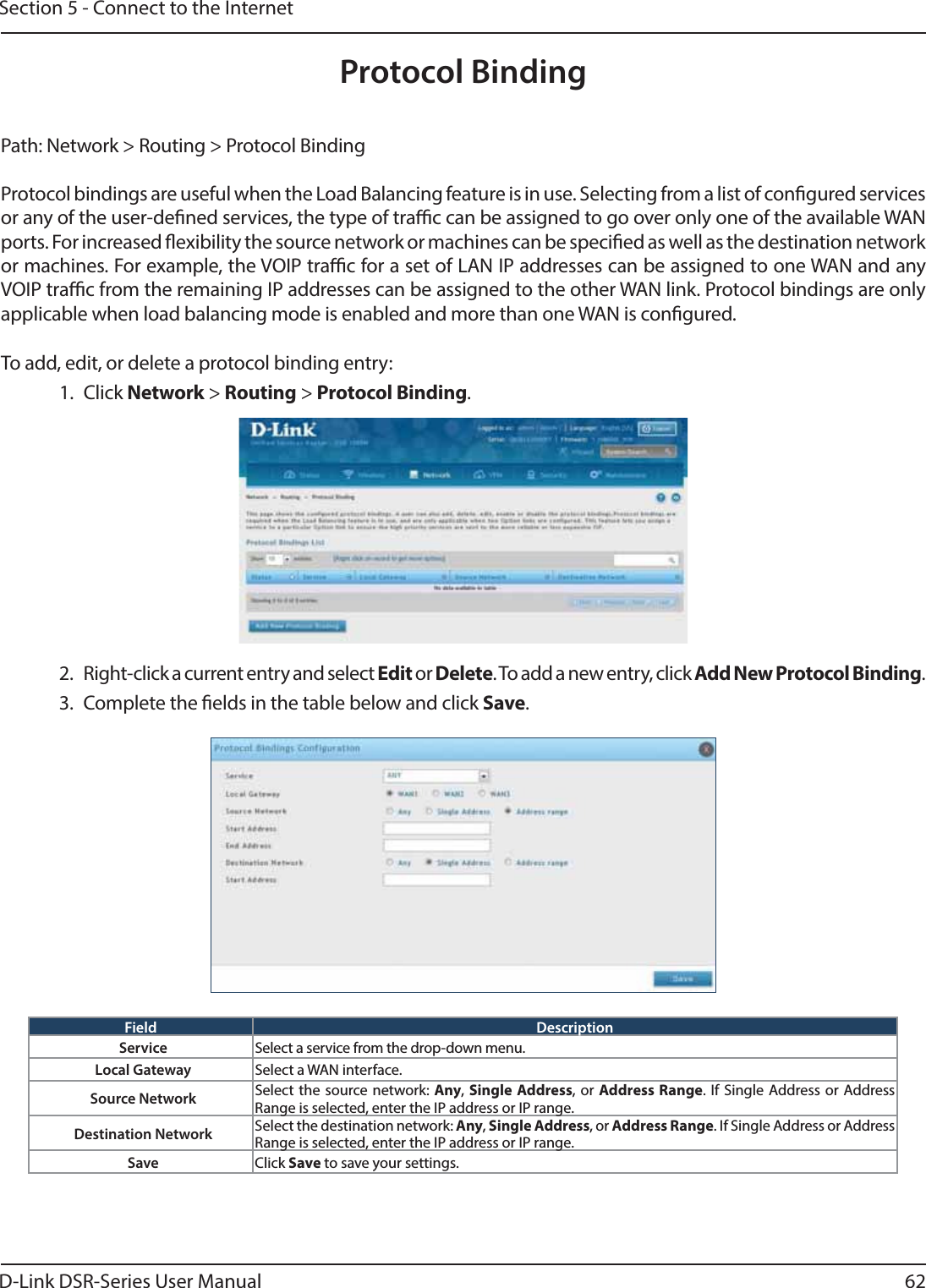
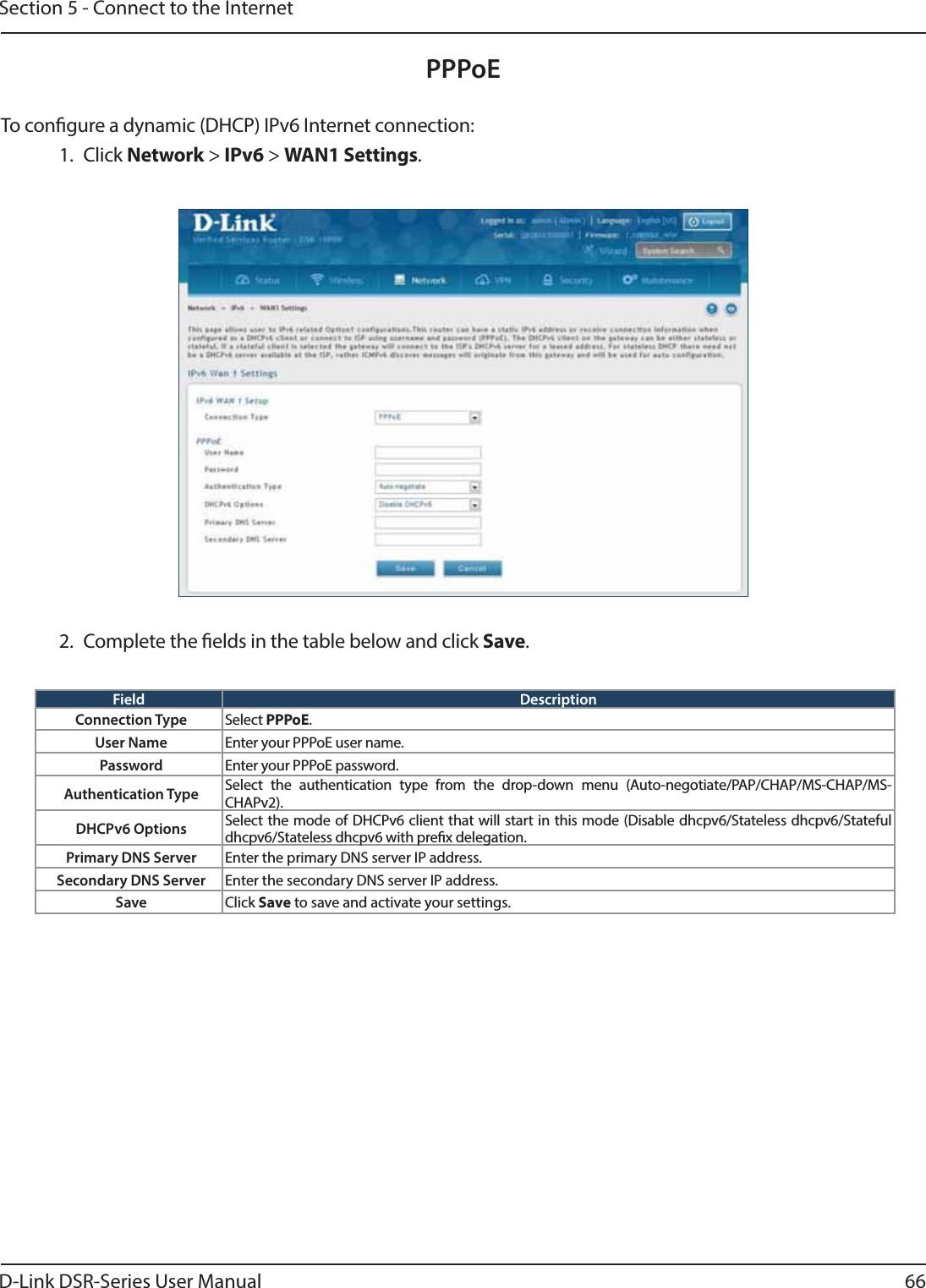
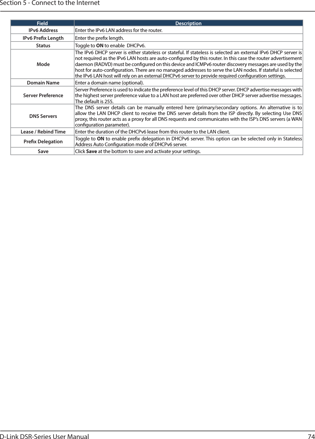
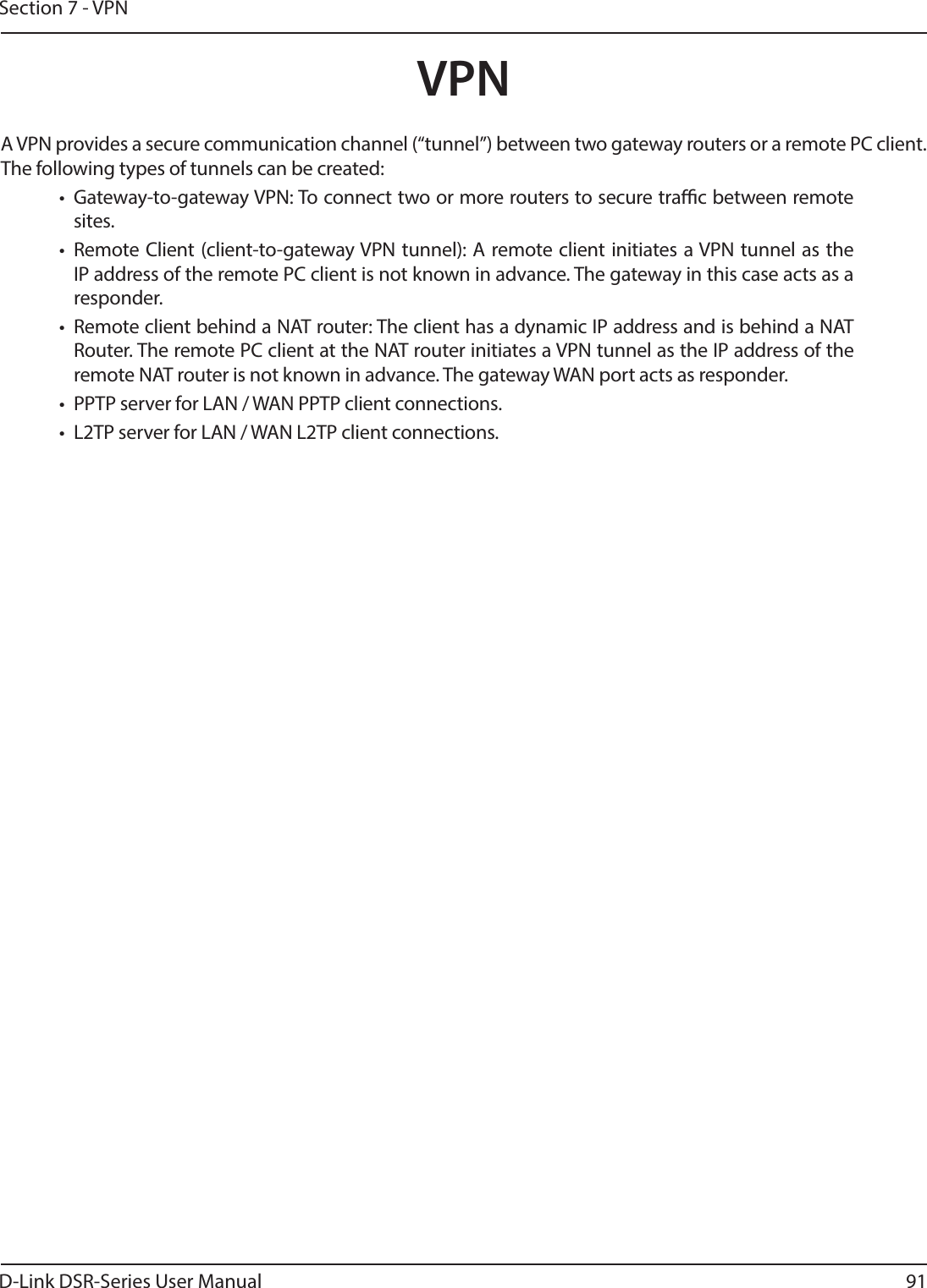
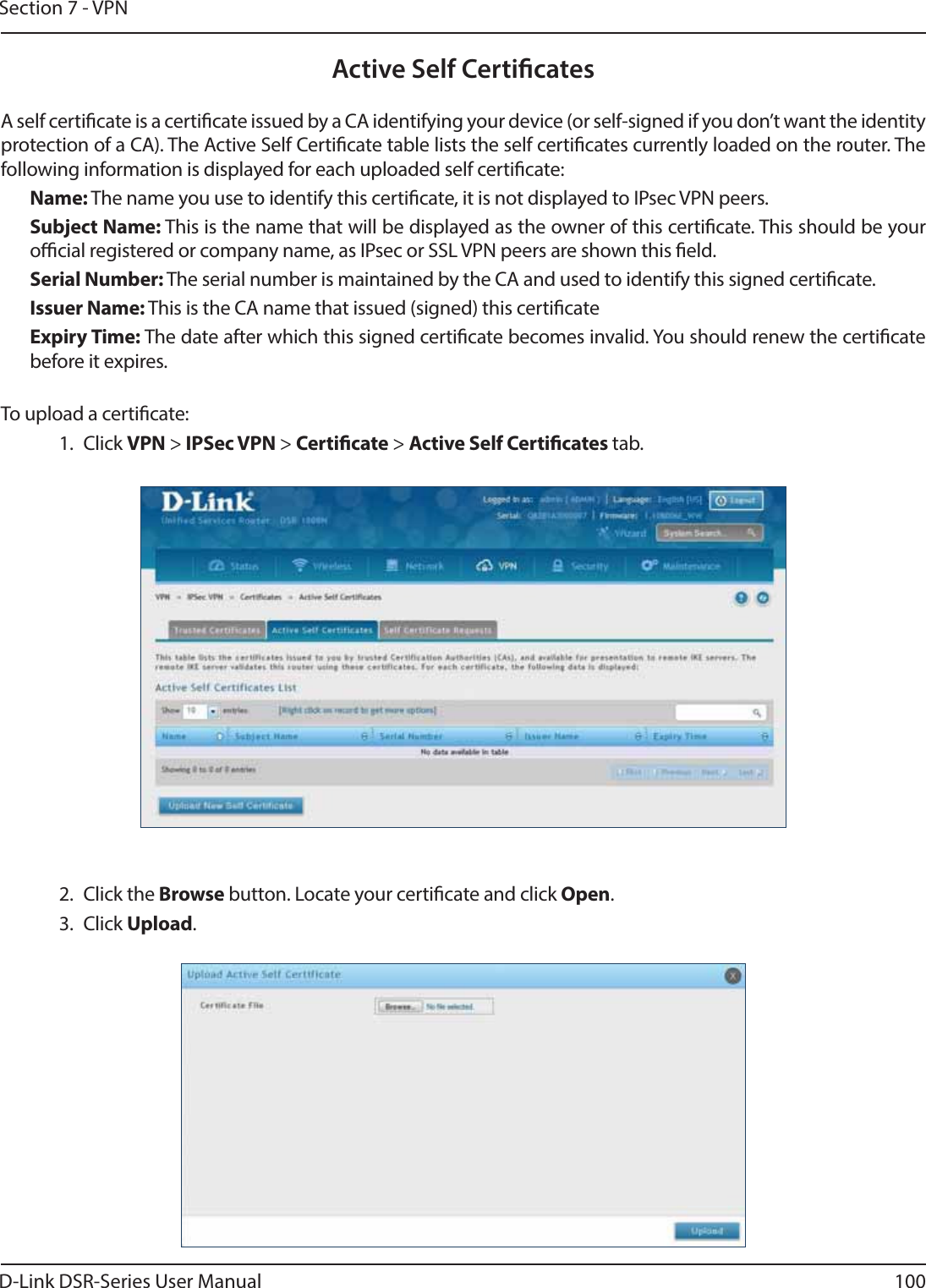
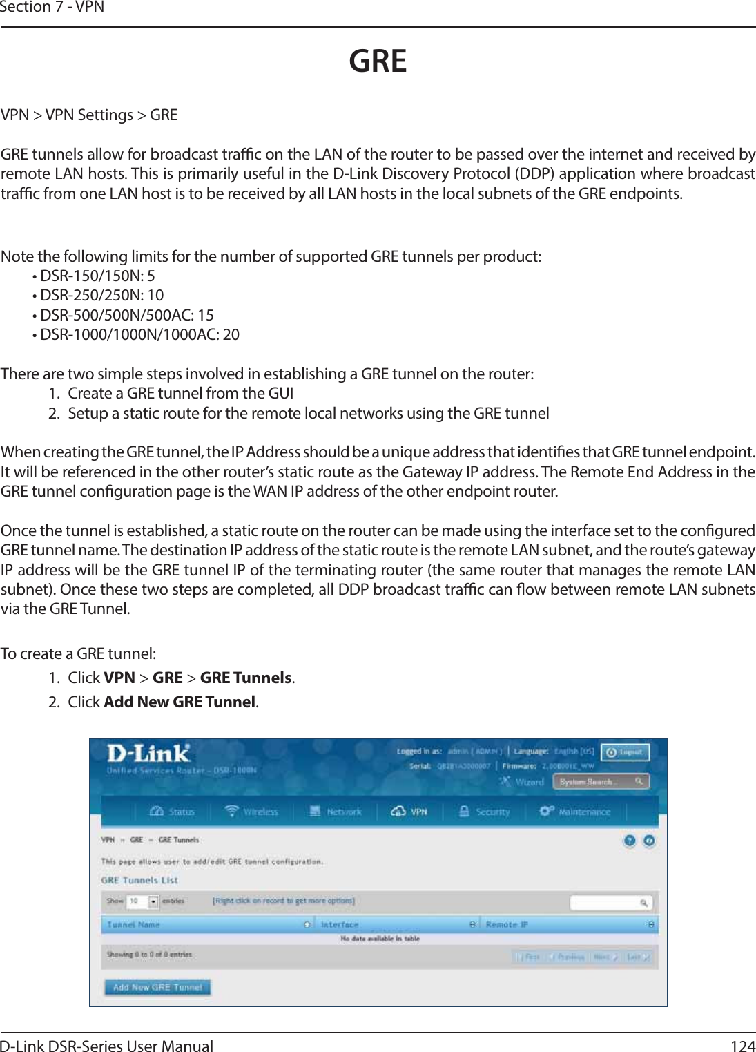
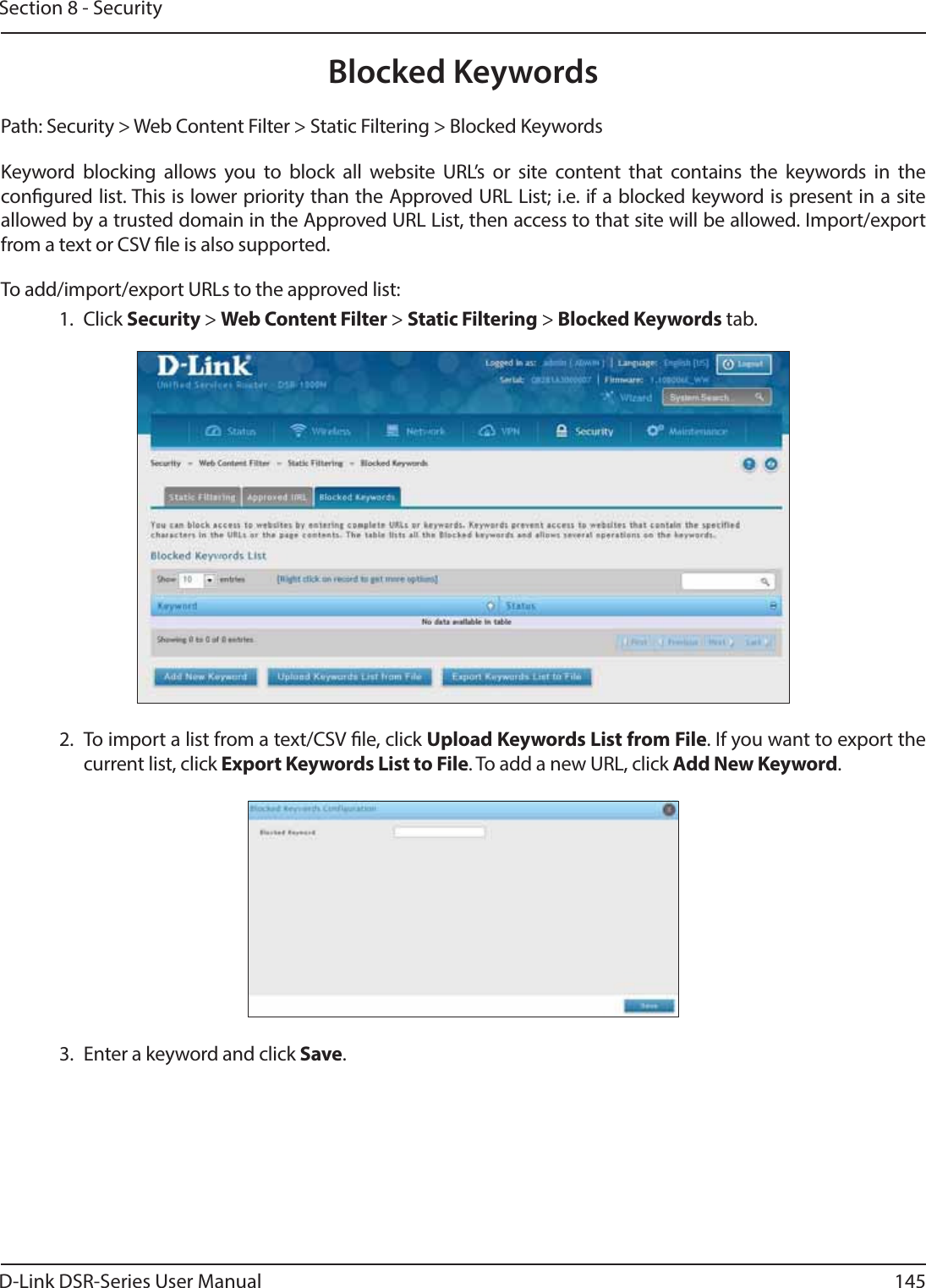
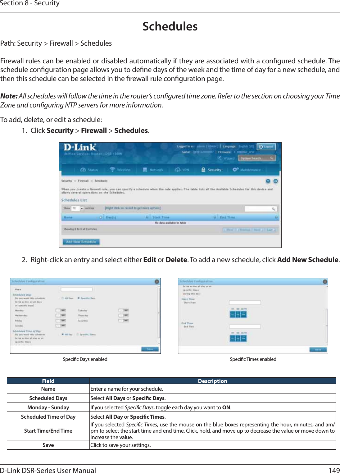
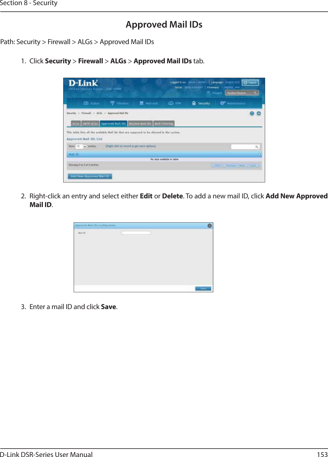
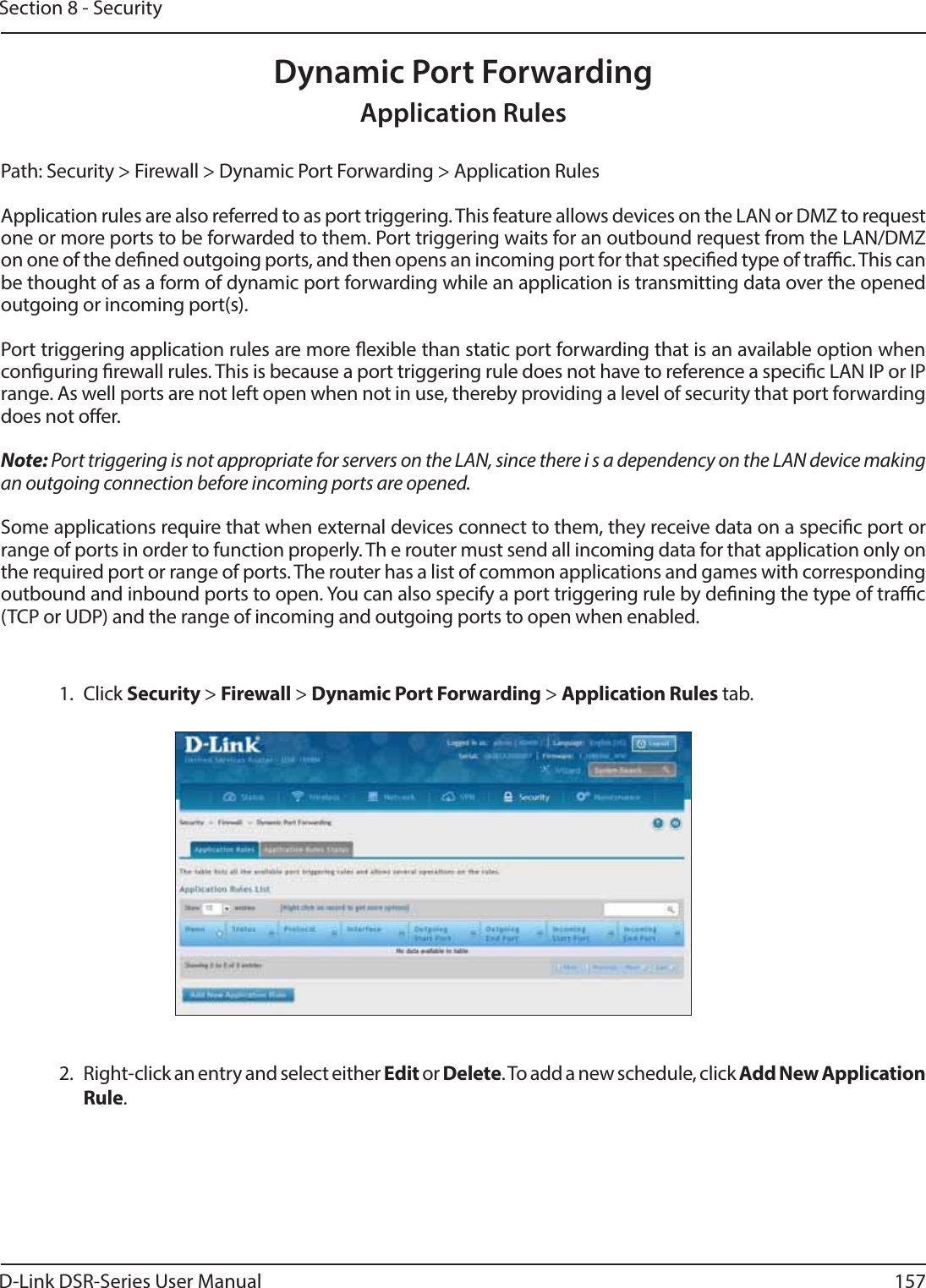
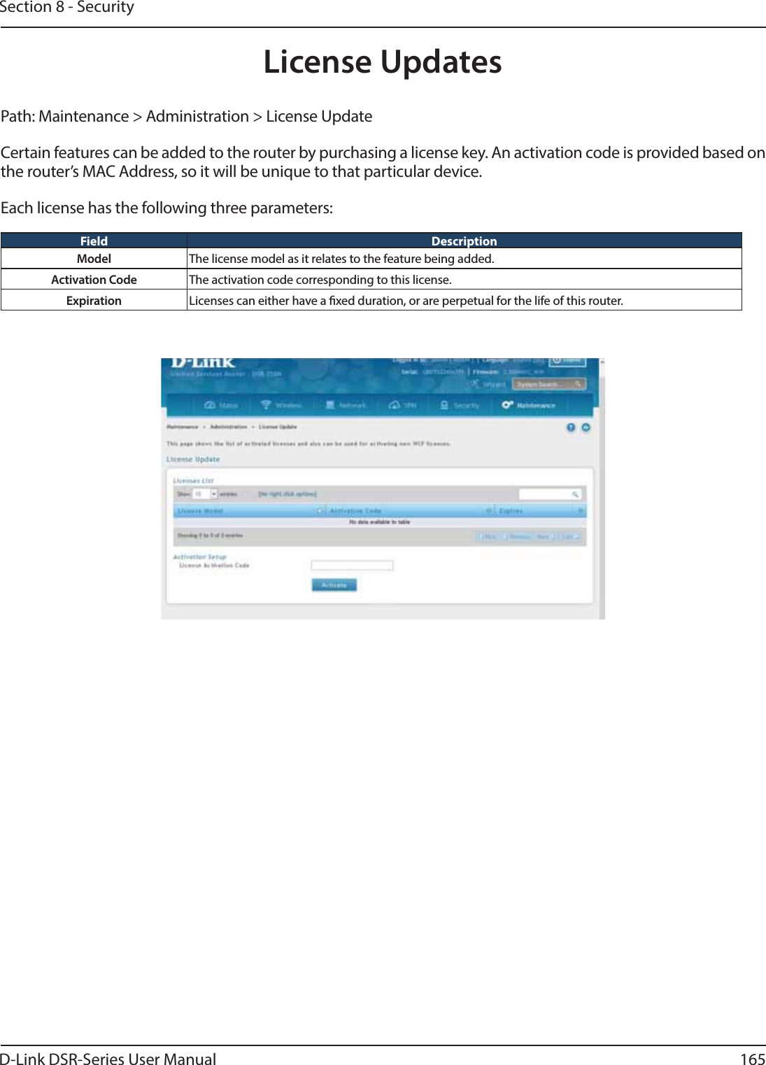
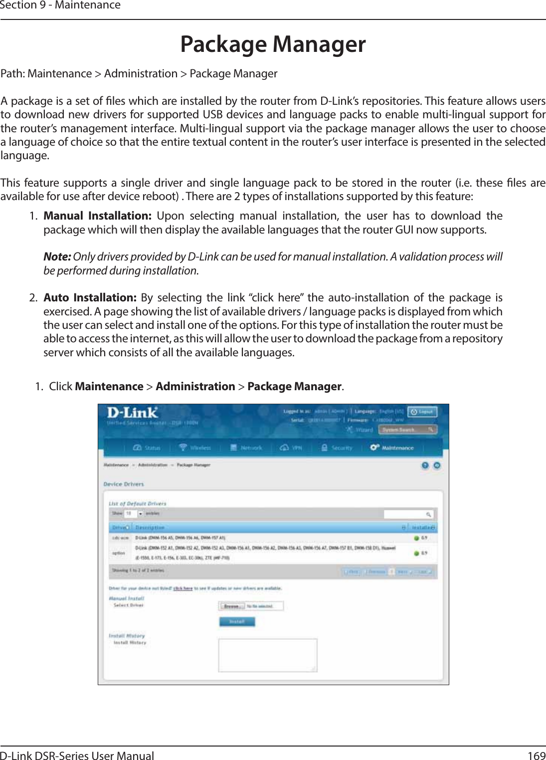
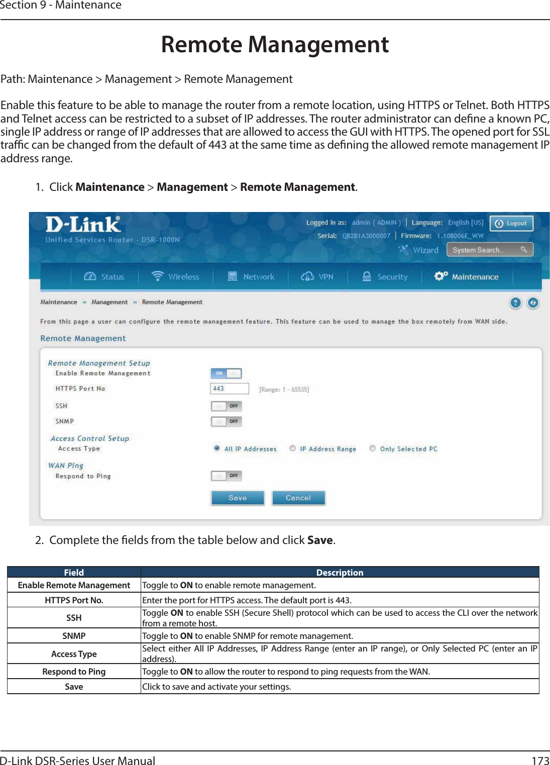
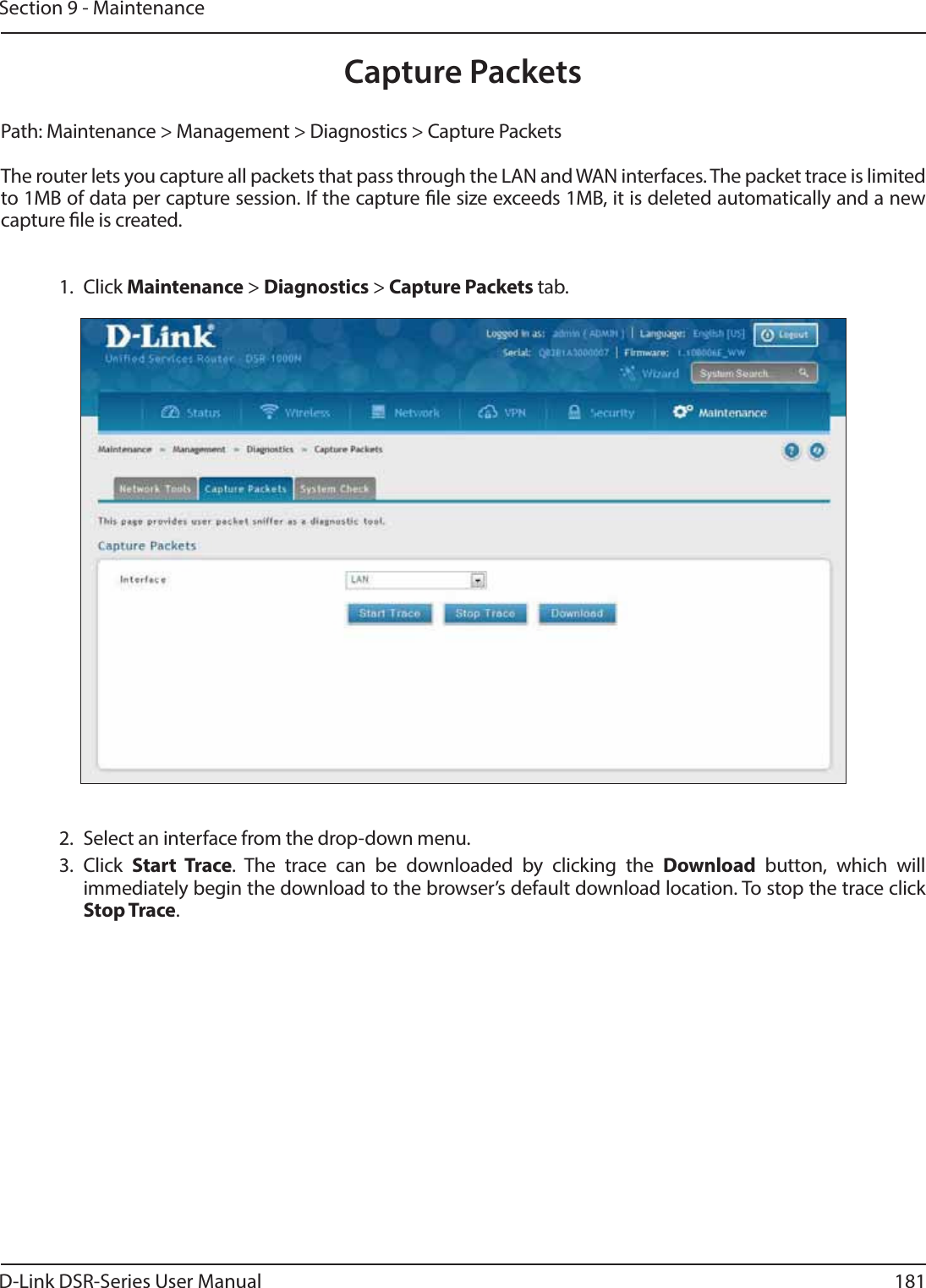
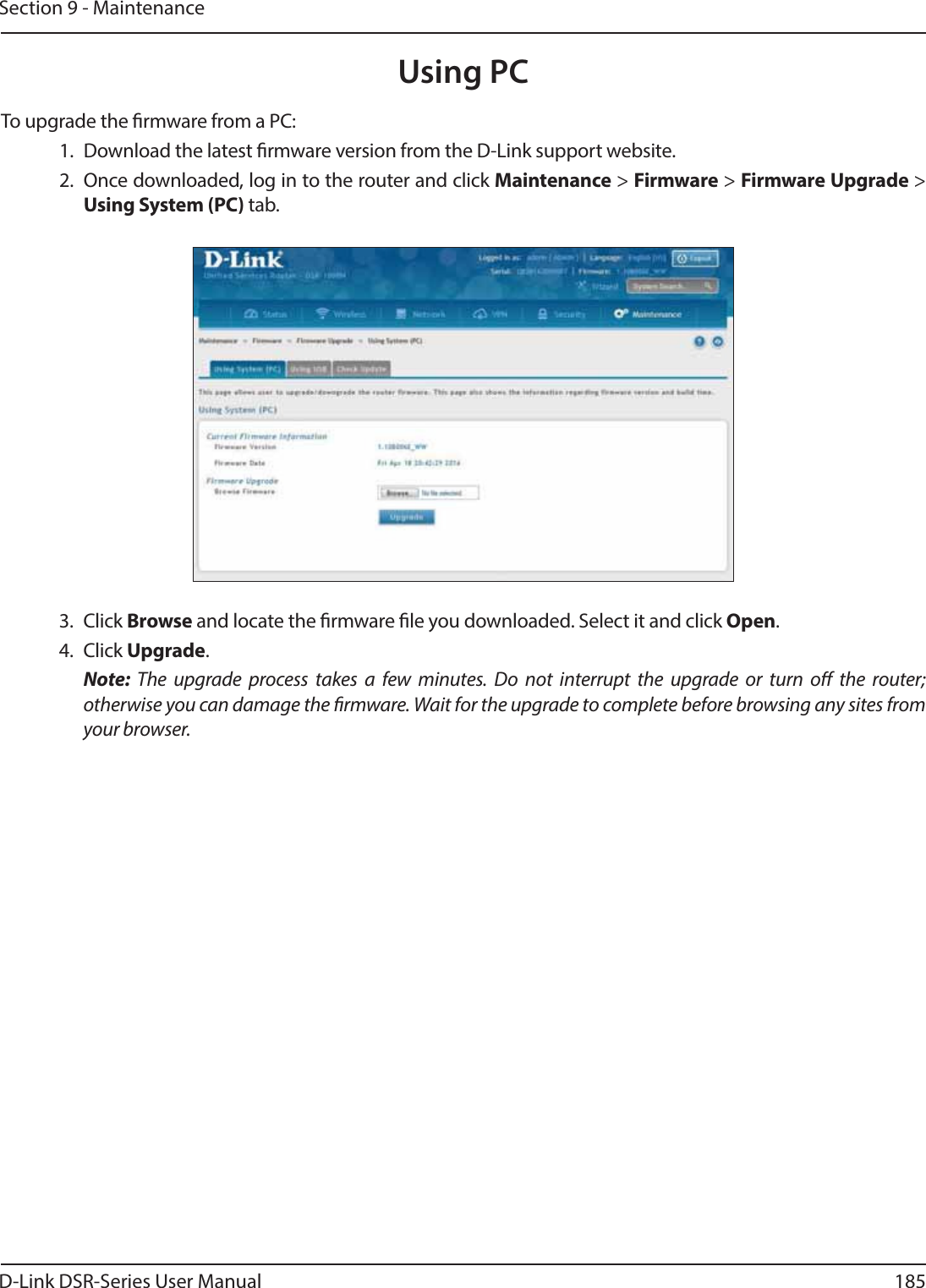
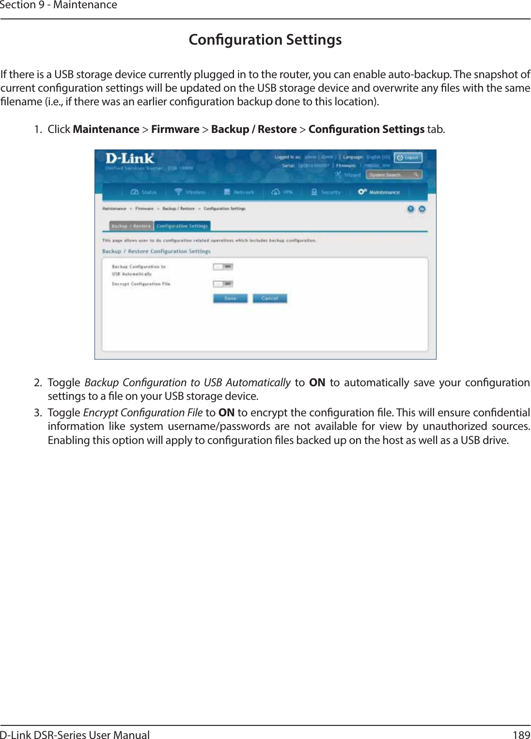
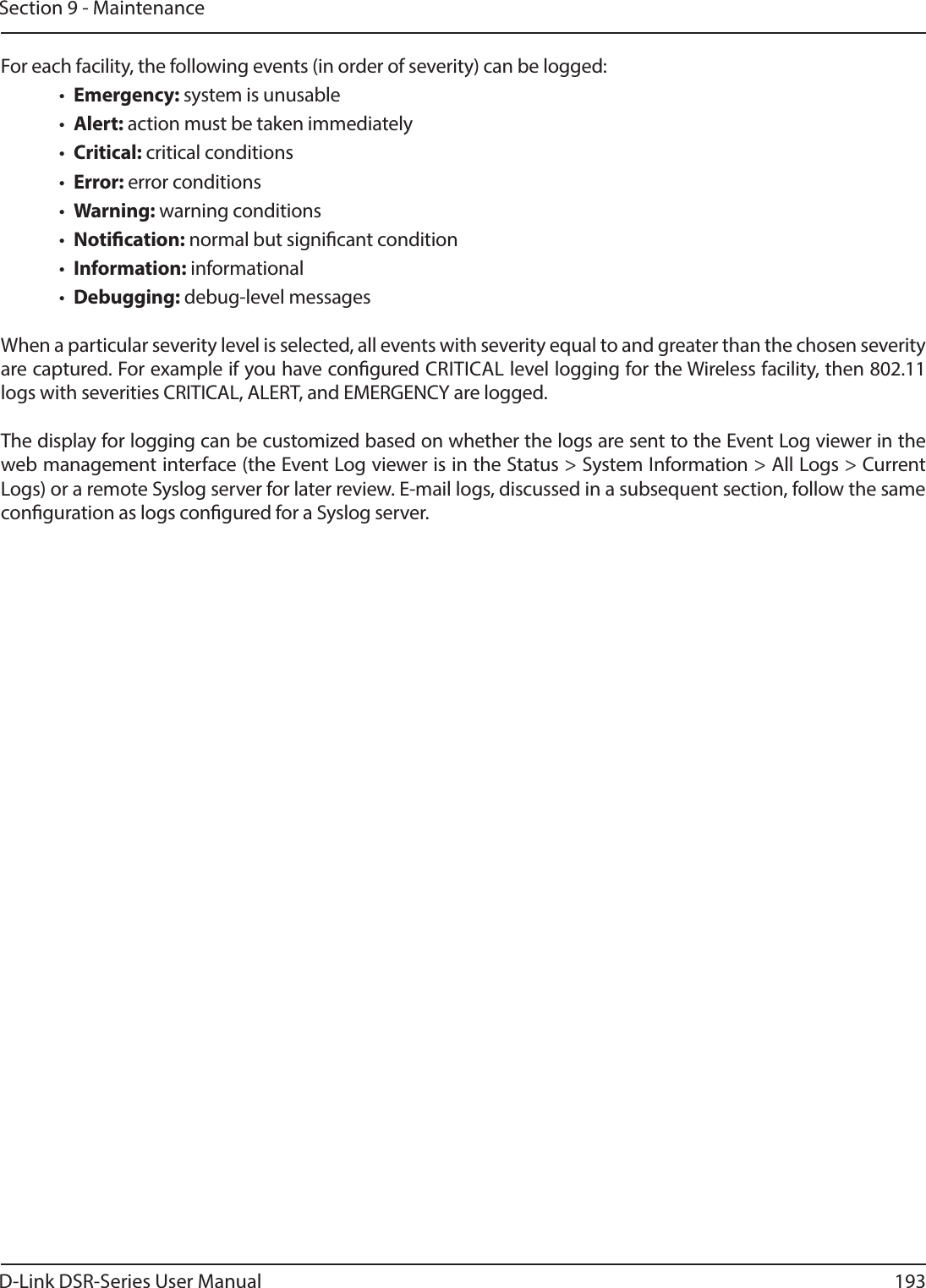
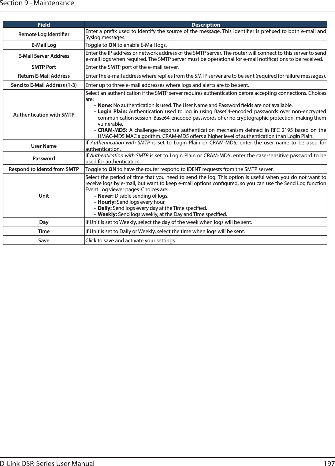
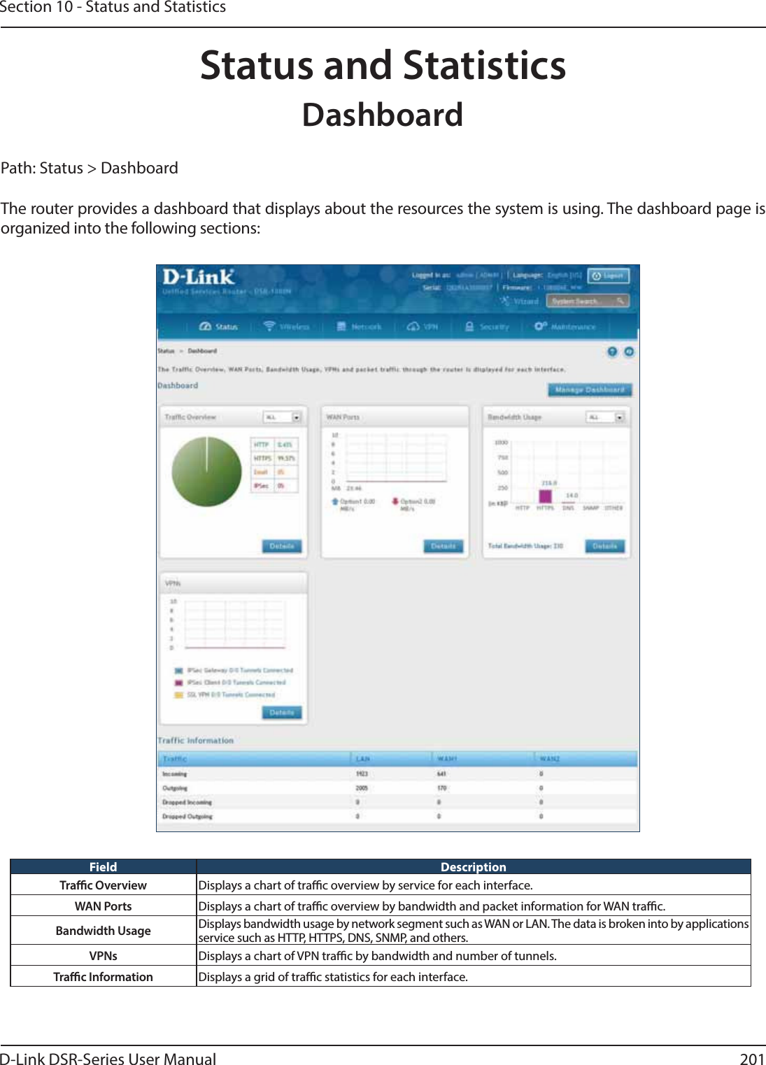
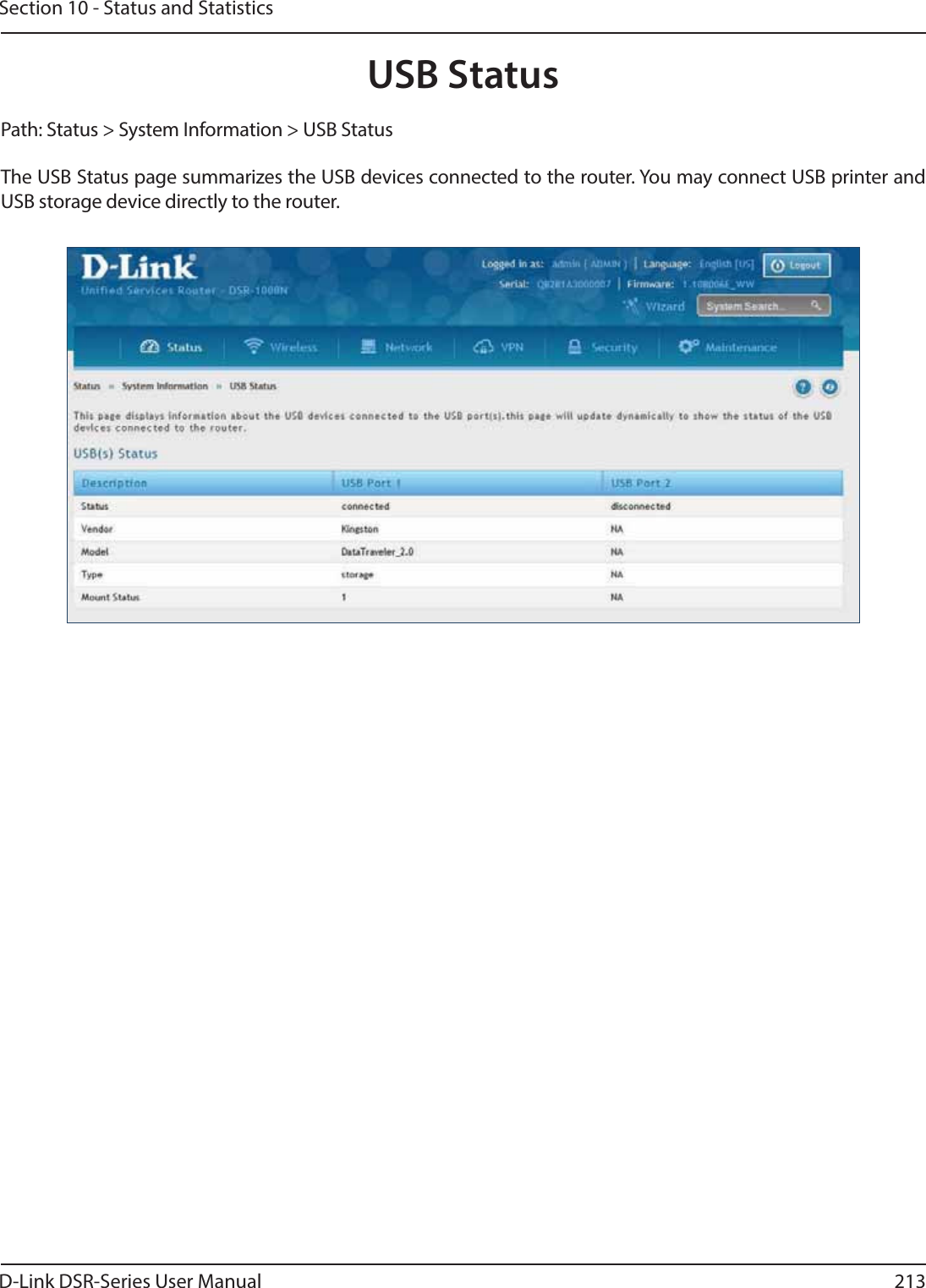
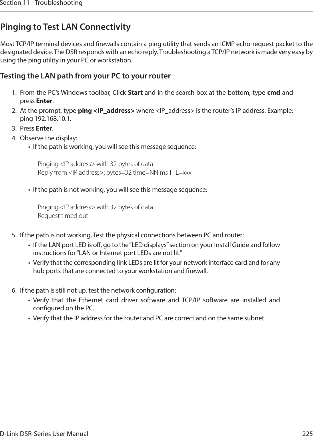
![D-Link DSR-Series User Manual 250Appendix D - Log Output ReferenceFacility: System (Admin)Log Message Severity Log Message SeverityUsage:%s <DBFile> DEBUG unable to register to UMI ERRORCould not open database: %s DEBUG sqlite3QueryResGet failed ERRORCPU LOG File not found DEBUG radSendtoServer: socket: %s ERRORMEM LOG File not found DEBUG radSendtoServer: bind() Failed: %s: %s ERRORcpuMemUsageDBUpdateHandler: update query: %s DEBUG radRecvfromServer: recvfrom() Failed: %s ERRORPrinting the whole list after inserting DEBUG radRecvfromServer: Packet too small from %s:%d: %s ERROR%s at %d(minute) %d(hour) %d(dayOfMonth) %d(month)” DEBUG radCheckMsgAuth: Invalid Message-Authenticator length in” ERRORadpCmdExec exited with return code=%d DEBUG radDictLoad: couldn’t open dictionary %s: %s ERROR %s op=%d row=%d DEBUG radBuildAndSendReq: Invalid Request Code %d ERRORsqlite3_mprintf failed DEBUG radPairAssign: bad attribute value length ERRORsqlite3QueryResGet failed: query=%s DEBUG radPairAssign: unknown attribute type %d ERRORPrinting the whole list after delete DEBUG radPairNew: unknown attribute %d ERROR%s at %d(minute) %d(hour) %d(dayOfMonth) %d(month)” DEBUG radPairGen: Attribute(%d) has invalid length ERRORPrinting the whole list after inserting DEBUG radPairValue: unknown attribute type %d ERROR%s at %d(minute) %d(hour) %d(dayOfMonth) %d(month)” DEBUG radPairValueLen: unknown attribute type %d ERRORemail logs: No logging events enabled DEBUG radPairLocate: Attribute(%d) has invalid length ERROR %s DEBUG radPairUnpackDefault: Unknown-Attribute[%d]: ERRORMail sent and the Database is reset. DEBUG radCongure: can’t open %s: %s ERRORDisabled syslog server DEBUG radCongure: %s: line %d: bogus format: %s ERROREvent logs are full, sending logs to email DEBUG radConfAssert: No AuthServer Specied ERROREmail logs sending failed DEBUG radConfAssert: No Default Timeout Specied ERRORPacking attribute: %s DEBUG radConfAssert: No Default Retry Count Specied ERRORServer found: %s, secret: %s DEBUG radExtractMppeKey: Invalid MS-MPPE-Key Length ERRORPacked Auth. Reqest: code:%d, id:%d, len:%d DEBUG radVendorMessage: Invalid Length in Vendor Message ERRORSending Packet to %x:%d .... DEBUG radVendorMessage: Unknown Vendor ID received:%d ERRORReceiving Reply Packet.... DEBUG radVendorAttrGet: Invalid Length in Vendor Message ERRORVeried Reply Packet Integrity DEBUG radVendorAttrGet: Unknown Vendor ID:%d ERRORGenerated Reply Attribute-Value pairs DEBUG radVendorMessagePack: Unknown Vendor ID:%d ERROR](https://usermanual.wiki/D-Link/SR500ACA1/User-Guide-2623752-Page-263.png)
![D-Link DSR-Series User Manual 253Appendix D - Log Output ReferenceCould not read data from le DEBUG Unable to initialize ntpControl ERRORntpTblHandler DEBUG ntpMgmt : Couldn’t open database %s ERRORstatus: %d DEBUG ERROR : incomplete DB update information ERRORtz: %d DEBUG empty update. nRows=%d nCols=%d ERRORDayLightsaving: %d DEBUG Error in executing DB update handler ERRORpNtpControl->ServerNames[PRIMARY_SERVER]: %s DEBUG requestNtpTime: Invalid addr ERRORpNtpControl->ServerNames[SECONDARY_SERVER]: %s DEBUG failed to take lock for compId: %d ERRORDS: %d DEBUG failed to convert ioctl args to buer for” ERRORpPriServ %s DEBUG request timeout dst(%d) <-- src(%d) ERRORpSecServ %s DEBUG failed to take lock for compId: %d ERRORMaking request from %d --> %d DEBUG umiIoctlArgsToBuf: failed to allocate memory ERRORsent request dst(%d) <-- src(%d) using option %d DEBUG umiRecvFrom: could not allocate memory ERRORreceived request too small!(%d bytes) DEBUG adpMalloc failed ERRORReceived a UMI request from %d DEBUG context with ID: %d already registered ERRORsent a reply src(%d) ---> dst(%d) DEBUG Failed to allocate memory for creating UMI context ERRORumiRegister (%x,%x,%x,%x) DEBUG Failed to create recvSem for UMI context ERRORsrcId=%d(%s) --> destId=%d(%s) cmd=%d inLen=%d outLen=%d DEBUG Failed to create mutex locks for UMI context ERRORwaiting for reply...Giving Up DEBUG Failed to create mutex recvQLock for UMI context ERRORNo request in the list after semTake DEBUG Invalid arguments to umiIoctl ERRORreply timeout DEBUG could not nd the destination context ERRORtimeout after semTake DEBUG memPartAlloc for %d size failed ERRORsrcId=%d(%s) <-- destId=%d(%s) cmd=%d DEBUG memPartAlloc for %d size failed ERROR Un-registerting component with Id %d DEBUG No Handler registered for this UMI context ERRORfailed to send ioctl request: dst(%d) <--- src(%d) DEBUG Couldn’t nd component with ID (%d),” ERRORprocessed a reply dst(%d) <-- src(%d) DEBUG id=%d handler=%x ERRORrequest with no result option dst(%d) <-- src(%d) DEBUG Received NULL buer in umiBufToIoctlArgs() ERRORcmd = %s DEBUG usbMgmtInit: unable to open the database le %s ERRORcmdstring is %s %s:%d DEBUG call to printCong failed ERRORCalling printerCong binary ... DEBUG Failed to Disable Network Storage” ERRORCalling unmount for USB ... DEBUG Some error occurred while removing device ERRORCalling mount for USB ... DEBUG Some error occurred while removing device ERRORusbdevice is %d %s:%d DEBUG Sqlite update failed ERROR](https://usermanual.wiki/D-Link/SR500ACA1/User-Guide-2623752-Page-266.png)
![D-Link DSR-Series User Manual 254Appendix D - Log Output ReferenceQuery string: %s DEBUG Failed to enable printer properly ERRORsqlite3QueryResGet failed.Query:%s DEBUG Failed to mount device on system ERROR%s: 1. usb is already disconnected for old usb type. “ DEBUG Failed to enable network storage device” ERROR%s: 2.call disable for new usb type ! DEBUG Failed to mount device on system ERROR%s: 3. usb is already disconnected for old usb type. “ DEBUG Sqlite update failed ERROR%s: 4. Disabled old usb type . Now “ DEBUG USB1 Touch failed ERRORusbdevice is %d %s:%d DEBUG USB2 Touch failed ERRORUSB: failed to begin transaction: %s DEBUG Sqlite update failed ERRORUSB: SQL error: %s pSetString = %s DEBUG Failed query: %s ERRORUSB: failed to commit transaction: %s DEBUG Failed to execute usb database update handler ERRORUSB: updated table: %s DEBUG Usage:%s <DBFile> <opType> <tblName> <rowId> ERRORUSB: returning with status: %s DEBUG Illegal invocation of snmpCong (%s) ERROR%s:DBUpdate event: Table: %s opCode:%d rowId:%d DEBUG Invalid Community Access Type ERRORexecuting %s status =%d DEBUG Invalid User Access Type ERRORexecuting %s DEBUG Invalid Security Level ERROR%s returned status=%d DEBUG Invalid Authentication Algorithm ERROR%s returned status=%d DEBUG Invalid Privacy Algorithm ERRORsnmpd.conf not found DEBUG Invalid Argument ERROR[SNMP_DEBUG] : Fwrite Successful DEBUG Failed to allocate memory for engineID ERROR[SNMP_DEBUG] : Fwrite failed DEBUG [SNMP_DEBUG]: Failed to get host address ERRORradPairGen: received unknown attribute %d of length %d WARN [SNMP_DEBUG] : FOPEN failed ERRORradPairGen: %s has unknown type WARN sqlite3QueryResGet failed.Query:%s ERRORradPairLocate: unknown attribute %ld of length %d WARN sqlite3QueryResGet failed.Query:%s ERRORradPairLocate: %s has unknown type WARN Invalid Security Level ERRORIllegal invocation of cpuMemUsage (%s) ERROR Invalid Authentication Algorithm ERRORcpuMemUsageDBUpdateHandler: SQL error: %s ERROR Invalid Privacy Algorithm ERRORunable to open the DB le %s ERROR Failed to Get Host Address ERRORumiInit failed ERROR Invalid version ERRORunable to register to UMI ERROR snmp v3 Trap Conguration Failed ERRORError Reading from the Database. ERROR sqlite3QueryResGet failed query:%s ERRORshort DB update event request! ERROR sqlite3QueryResGet failed.Query:%s ERRORError in executing DB update handler ERROR Failed to Open Snmp Conguration File ERROR](https://usermanual.wiki/D-Link/SR500ACA1/User-Guide-2623752-Page-267.png)
![D-Link DSR-Series User Manual 257Appendix D - Log Output ReferenceDisabling attack check for TCP Flood. DEBUG prerouting Firewall Rule add for Relay failed DEBUGDisabling attack check for UDP Flood. DEBUG Deleting MAC Filter Policy for Address %s DEBUGDisabling attack check for IPsec. DEBUG Adding MAC Filter Policy for Address %s DEBUGDisabling attack check for PPTP. DEBUG Disabling Firewall Rules for DMZ host DEBUGDisabling attack check for L2TP. DEBUG Enabling Firewall Rules for DMZ host DEBUGDisabling attack check for UDP Flood. DEBUG Disabling Firewall Rules for Spill Over Load Balancing DEBUGDisabling attack check for IPsec. DEBUG Disabling Firewall Rules for Load Balancing DEBUGDisabling attack check for PPTP. DEBUG Enabling Firewall Rules for Load Balancing DEBUGDisabling attack check for L2TP. DEBUG Enabling Firewall Rules for Spill Over Load Balancing DEBUGEnabling attack check for Block ping to WAN “ DEBUG Enabling Firewall Rules for Auto Failover DEBUGEnabling attack check for Stealth Mode for tcp. DEBUG Enabling Firewall Rules for Load Balancing . DEBUGEnabling attack check for Stealth Mode for udp. DEBUG Enabling Firewall Rules for Spill Over Load Balancing . DEBUGEnabling attack check for TCP Flood. DEBUG Enabling Firewall Rules for Auto Failover DEBUGEnabling attack check for UDP Flood. DEBUG Deleting BlockSites Keyword \ DEBUGEnabling attack check for IPsec. DEBUG Enabling BlockSites Keyword \ DEBUGEnabling attack check for PPTP. DEBUG Disabling BlockSites Keyword \ DEBUGEnabling attack check for L2TP. DEBUG Updating BlockSites Keyword from \ DEBUGEnabling attack check for UDP Flood. DEBUG Inserting BlockSites Keyword \ DEBUGEnabling attack check for IPsec. DEBUG Deleting Trusted Domain \ DEBUGEnabling attack check for PPTP. DEBUG Adding Trusted Domain \ DEBUGEnabling attack check for L2TP. DEBUG Restarting Schedule Based Firewall Rules DEBUGEnabling DoS attack check with %d SyncFlood detect rate, “ DEBUG Enabling Remote SNMP DEBUGDisabling DoS attack check having %d SyncFlood detect rate,” DEBUG Disabling Remote SNMP DEBUGEnabling ICSA Notication Item for ICMP notication. DEBUG Enabling Remote SNMP DEBUGEnabling ICSA Notication Item for Fragmented Packets. DEBUG Disabling DOS Attacks DEBUGEnabling ICSA Notication Item for Multi cast Packets. DEBUG Enabling DOS Attacks DEBUGDisabling ICSA Notication Item for ICMP notication. DEBUG Enabling DOS Attacks DEBUGDisabling ICSA Notication Item for Fragmented Packets. DEBUG Restarting Firewall [%d]:[%d] For %s DEBUGDisabling ICSA Notication Item for Multi cast Packets. DEBUG restartStatus = %d for LogicalIfName = %s DEBUG](https://usermanual.wiki/D-Link/SR500ACA1/User-Guide-2623752-Page-270.png)
![D-Link DSR-Series User Manual 260Appendix D - Log Output ReferenceRestarting Firewall For %s Address Update from %s:%s DEBUG nimfBridgeTblHandler: unable to get interfaceName ERRORDisabling Firewall Rule for MSS packet marking DEBUG nimfBridgeTblHandler: \ ERROREnabling Firewall Rule for MSS packet marking DEBUG nimfBridgeTblHandler: unable to get \ ERROREnabling packet marking rule for %s IDLE timer DEBUG Failed to %s trac from %s to %s to IPS. ERRORDeleted rewall rule %s for service %s with action %s DEBUG Failed to %s trac from %s to %s to IPS. ERROR%s rewall rule %s for service %s with action %s DEBUG failed to start IPS service. ERRORAdded rewall rule %s for service %s with action %s DEBUG Timeout in waiting for IPS service to start. ERRORDeleting inbound(WAN-LAN) rewall rule. DEBUG Usage:%s <DBFile> <opType> <tblName> <rowId> “ ERRORDeleting inbound(WAN-DMZ) rewall rule. DEBUG xlr8NatCong: illegal invocation of (%s) ERRORRIPng disabled. DEBUG Illegal invocation of [%s] ERRORRIPng enabled. DEBUG xlr8NatMgmtTblHandler: failed query: %s ERRORDisable IPv6 rewall rule. DEBUG Could not open le: %s ERROREnable IPv6 rewall rule. DEBUG Rip Error Command Too Long ERRORDeleting IGMP proxy rule. DEBUG No authentication for Ripv1 ERROREnable IGMP proxy rule. DEBUG Invalid Rip Direction ERRORRestarting IGMP rule. DEBUG Invalid Rip Version ERRORTrac meter enabled with no limit type. DEBUG Invalid Password for 1st Key ERRORTrac meter enabled for only download. DEBUG Invalid Time for 1st Key ERRORTrac meter enabled for both directions. DEBUG Invalid Password for 2nd Key ERRORDeleted rewall rule %s for service %s with action %s DEBUG Invalid Time for 2nd Key ERROR%s rewall rule %s for service %s with action %s DEBUG Invalid First KeyId ERRORAdded rewall rule %s for service %s with action %s DEBUG Invalid Second KeyId ERROREnabling Inter VLAN routing. DEBUG Invalid Authentication Type ERRORUpdating inter VLAN routing status. DEBUG ripDisable failed ERRORDeleting inter VLAN routing. DEBUG ripEnable failed ERROR](https://usermanual.wiki/D-Link/SR500ACA1/User-Guide-2623752-Page-273.png)
![D-Link DSR-Series User Manual 266Appendix D - Log Output Referencefrom pnacPDUProcess: code = %d, identier = %d, “ DEBUG eapolRecvKeyMsg: MIC bit must be set ERRORfrom pnacPDUProcess: setting rxResp true DEBUG wpaAuthRecvPTKMsg2: unexpected packet received ERRORfrom pnacPDUProcess: code = %d, identier = %d, “ DEBUG wpaAuthRecvPTKMsg2: mic check failed ERRORfrom pnacPDUProcess: received “ DEBUG wpaAuthRecvPTKMsg2: rsn ie mismatch ERRORfrom pnacPDUProcess: received “ DEBUG wpaAuthRecvPTKMsg4: unexpected packet received ERRORfrom pnacPDUProcess: received PNAC_EAPOL_KEY_PACKET DEBUG wpaAuthRecvPTKMsg4: keyDataLength not zero ERRORdoing pnacTxCannedFail DEBUG wpaAuthRecvPTKMsg4: mic check failed ERRORdoing pnacTxCannedSuccess DEBUG wpaAuthRecvGTKMsg2: unexpected packet received ERRORdoing pnacTxReqId DEBUG secureBit not set in GTK Msg2 ERRORdoing pnacTxReq DEBUG wpaAuthRecvGTKMsg2: keyDataLength not zero ERRORdoing pnacTxStart DEBUG wpaAuthRecvGTKMsg2: mic check failed ERRORdoing pnacTxLogo DEBUG wpaAuthRecvKeyReq: unexpected packet received ERRORdoing pnacTxRspId: 1st cond DEBUG wpaAuthRecvKeyReq: keyDataLength not zero ERRORdoing pnacTxRspId: entering 2nd cond DEBUG wpaAuthRecvKeyReq: mic check failed ERRORfrom pnacTxRspId: code = %d, identier = %d, length = %d, “ DEBUG invalid OUI %x %x %x ERRORdoing pnacTxRspId: 2nd cond DEBUG (%s) invalid OUI %x %x %x ERRORdoing pnacTxRspAuth: 1st cond DEBUG [%s:%d] Cipher in WPA IE : %x ERRORdoing pnacTxRspAuth: 2nd cond DEBUG (%s) invalid OUI %x %x %x ERROR message for unknown port PAE DEBUG short WPA IE (length = %d) received ERRORfrom pnacACToSuppRecvRtn: calling pnacEapPktRecord DEBUG PTK state machine in unknown state. ERRORfrom pnacEapPktRecord: code = %d, identier = %d, “ DEBUG dot11InstallKeys failed ERRORfrom pnacEapPktRecord: received success pkt DEBUG group state machine entered into WPA_AUTH_GTK_INIT ERRORfrom pnacEapPktRecord: received failure pkt DEBUG dot11Malloc failed ERRORfrom pnacEapPktRecord: received request pkt DEBUG dot11Malloc failed ERRORunknown EAP-code %d DEBUG dot11Malloc failed ERRORAuthenticator[%d]: DEBUG aesWrap failed ERRORAuth PAE state = %s DEBUG unknown key descriptor version %d ERRORAuth Reauth state = %s DEBUG dot11Malloc failed ERRORBack auth state = %s DEBUG could not initialize AES128ECB ERROR](https://usermanual.wiki/D-Link/SR500ACA1/User-Guide-2623752-Page-279.png)
![D-Link DSR-Series User Manual 267Appendix D - Log Output ReferenceSupplicant[%d]: DEBUG could not initialize AES-128-ECB ERRORSupp Pae state = %s DEBUG MD5 initialization failed ERRORfrom pnacBackAuthFail: calling pnacTxCannedFail DEBUG RC4 framework initialization failed ERROR%s returned ERROR DEBUG PNAC framework initialization failed ERRORpnacUmiIoctlHandler: cmd: %s(%d) DEBUG ERROR: option value not specied ERROR%s not congured for 802.1x DEBUG ERROR: -u can be used only with -s ERRORcould not process PDU received from the wire DEBUG ERROR: user-name not specied ERRORpnacPDUForward: failed to foward the received PDU DEBUG failed to enable debug ERRORCreating PHY port with AUTH backend : %s SendRtn: %p RecvRtn:%p DEBUG [%s]: failed to convert string to MAC “ ERRORpnacUmiAuthCong: %s not congured for 802.1x DEBUG failed to initialize UMI ERRORpnacSuppRegisterUserInfo: not a valid AC DEBUG pnacPhyPortParamSet:invalid arguments ERRORpnacIfCong: autoAuth Enabled DEBUG pnacPhyPortParamSet:Failed to create socket ERRORpnacSendRtn: no pnac port pae found for “ DEBUG Error from pnacPhyPortParamSet:%s-device invalid ERRORsending portStatus: %s[%d] to dot11 DEBUG Error from pnacPhyPortParamSet:%s-Getting MAC address “ ERRORpnacRecvASInfoMessage: Rkey of length %d set DEBUG pnacPhyPortParamSet:Failed to add 802.1X multicast “ ERRORASSendRtn: %p ASToAuthRecv: %p DEBUG pnacIsInterfaceUp: failed to create a raw socket ERRORadpRand failed:unable to generate random unicast key WARN pnacIsInterfaceUp: failed to get interface ags ERRORusing group key as unicast key WARN failed to allocate buer ERRORIntegrity check failed more than once in last 60 secs. WARN UMI initialization failed ERRORMIC failed twice in last 60 secs, taking countermeasures WARN UMI initialization failed ERRORFailed to set dot11 port status WARN Error from pnacEapDemoAuthLibInit: malloc failed ERRORPTK state machine in NO_STATE. WARN Error from pnacEapDemoAuthRecv: received null EAP pkt ERRORPTK state machine in NO_STATE!! WARN Error from pnacEapDemoAuthRecv: send “ ERROR](https://usermanual.wiki/D-Link/SR500ACA1/User-Guide-2623752-Page-280.png)
![D-Link DSR-Series User Manual 271Appendix D - Log Output ReferenceProle %s does not exist ERROR Error from pnacTxCannedSuccess: eap pkt create failed ERRORProle %s does not exist ERROR Error from pnacTxReqId: eap pkt create failed ERRORinvalid type value %d. supported values are 1,2,3,4 ERROR Error from pnacTxReq: eap pkt create failed ERRORProle %s does not exist ERROR Error from pnacSendRespToServer: malloc failed ERRORinvalid type value %d. supported values are 1,2,3,4 ERROR Error from pnacSendRespToServer: no AS congured ERRORProle %s does not exist ERROR Error from pnacTxStart: basic pkt create failed ERRORinvalid type value %d. supported values are 1,2,3,4 ERROR Error from pnacTxStart: basic pkt create failed ERRORProle %s does not exist ERROR Error from pnacTxRspId: eap pkt create failed ERRORinvalid type value %d. supported values are 1,2,3,4 ERROR Error from pnacTxRspAuth: eap pkt create failed ERRORProle %s does not exist ERROR Error from pnacEapPktRecord: EAP packet too” ERRORinvalid type value %d. supported values are 1,2,3,4 ERROR Error from pnacEapPktRecord: “ ERRORProle %s does not exist ERROR from pnacBackAuthTimeout: calling pnacTxCannedFail ERRORERROR: incomplete DB update information. ERROR hmac_md5: adpHmacContextCreate failed ERRORold values result does not contain 2 rows ERROR hmac_md5:adpHmacInit failed ERRORsqlite3QueryResGet failed ERROR pnacUmiIoctlHandler: invalid cmd: %d ERRORError in executing DB update handler ERROR pnacEapRadAuthSend: Invalid arguments ERRORsqlite3QueryResGet failed ERROR pnacEapRadAuthSend: failed to allocate inbuer ERRORERROR: incomplete DB update information. ERROR pnacXmit : umiIoctl failed[%d] ERRORold values result does not contain 2 rows ERROR pnacPDUForward: Invalid input ERRORsqlite3QueryResGet failed ERROR pnacPDUForward: error in getting port pae information ERRORError in executing DB update handler ERROR pnacPDUForward: error allocating memory ERRORsqlite3QueryResGet failed.Query:%s ERROR pnacUmiIfMacAddrChange: %s not congured for 802.1x ERRORsqlite3QueryResGet failed.Query:%s ERROR pnacUmiIfMacAddrChange: could not process PDU received” ERRORsqlite3QueryResGet failed.Query:%s ERROR pnacUmiPhyPortCong: Invalid cong data ERRORsqlite3QueryResGet failed.Query:%s ERROR pnacUmiPhyPortCong: Invalid backend name specied ERRORstartStopVap failed to stop %s ERROR pnacUmiPhyPortCong: could not create PNAC physical” ERRORInvalid SQLITE operation code - %d ERROR pnacUmiAuthCong: Invalid cong data ERROR./src/dot11/mgmt/dot11Mgmt.c:1177: ADP_ERROR ( ERROR pnacUmiAuthCong: Invalid backend name specied ERRORonly delete event expected on dot11RogueAP. ERROR unable to create new EAP context. ERRORsqlite3QueryResGet failed ERROR unable to apply %s prole on the EAP context. ERRORunhandled database operation %d ERROR pnacUmiAuthCong: could not congure PNAC PAE “ ERROR](https://usermanual.wiki/D-Link/SR500ACA1/User-Guide-2623752-Page-284.png)
![D-Link DSR-Series User Manual 272Appendix D - Log Output Referencesqlite3QueryResGet failed ERROR pnacUmiSuppCong: Invalid cong data ERRORfailed to congure WPS on %s ERROR pnacUmiSuppCong: Invalid backend name specied ERRORsqlite3QueryResGet failed ERROR pnacUmiSuppCong: %s not congured for 802.1x ERRORsqlite3QueryResGet failed ERROR pnacUmiSuppCong: could not PNAC port Access” ERRORsqlite3QueryResGet failed ERROR pnacUmiSuppCong: Failed to register user information ERRORsqlite3QueryResGet failed ERROR pnacPortByMacDecong: port not found ERRORsqlite3QueryResGet failed ERROR pnacPortByMacDecong: port not found ERRORno VAP rows returned. expected one ERROR pnacUmiIfDown: Invalid cong data ERRORmultiple VAP rows returned. expected one ERROR pnacUmiIfDown: Invalid cong data ERRORsqlite3QueryResGet failed ERROR Error from pnacPortDecong: port not congured ERRORinvalid query result. ncols=%d nrows=%d ERROR pnacUmiIfDown: could not de-congure port ERROR%s:VAP(%s) create failed ERROR pnacUmiPhyPortDestroy: Invalid cong data ERRORsqlite3QueryResGet failed ERROR pnacUmiPhyPortDestroy: Invalid cong data ERRORinvalid query result. ncols=%d nrows=%d ERROR pnacUmiPhyPortDestroy: Failed to destroy the port ERROR Invalid cong data ERRORFacility: KernelLog Message Severity Log Message SeverityDNAT: multiple ranges no longer supported DEBUG %s: %s%s:%d -> %s:%d %s, DEBUGDNAT: Target size %u wrong for %u ranges, DEBUG %s: %s%s:%d %s, DEBUGDNAT: wrong table %s, tablename DEBUG %s: Failed to add WDS MAC: %s, dev->name, DEBUGDNAT: hook mask 0x%x bad, hook_mask DEBUG %s: Device already has WDS mac address attached, DEBUG%s%d: resetting MPPC/MPPE compressor, DEBUG %s: Added WDS MAC: %s, dev->name, DEBUG%s%d: wrong oset value: %d, DEBUG %s: WDS MAC address %s is not known by this interface, DEBUG%s%d: wrong length of match value: %d, DEBUG [madwi] %s() : Not enough space., __FUNCTION__ DEBUG%s%d: too big oset value: %d, DEBUG Returning to chan %d, ieeeChan DEBUG%s%d: cannot decode oset value, DEBUG WEP DEBUG%s%d: wrong length code: 0x%X, DEBUG AES DEBUG%s%d: short packet (len=%d), __FUNCTION__, DEBUG AES_CCM DEBUG%s%d: bad sequence number: %d, expected: %d, DEBUG CKIP DEBUG](https://usermanual.wiki/D-Link/SR500ACA1/User-Guide-2623752-Page-285.png)
![D-Link DSR-Series User Manual 273Appendix D - Log Output Reference%s%d: bad sequence number: %d, expected: %d, DEBUG TKIP DEBUGPPPIOCDETACH le->f_count=%d, DEBUG %s: cannot map channel to mode; freq %u ags 0x%x, DEBUGPPP: outbound frame not passed DEBUG %s: %s, vap->iv_dev->name, buf DEBUGPPP: VJ decompression error DEBUG %s: [%s] %s, vap->iv_dev->name, DEBUGPPP: inbound frame not passed DEBUG %s: [%s] %s, vap->iv_dev->name, ether_sprintf(mac), buf DEBUGPPP: reconstructed packet DEBUG [%s:%s] discard %s frame, %s, vap->iv_dev->name, DEBUGPPP: no memory for DEBUG [%s:%s] discard frame, %s, vap->iv_dev->name, DEBUG missed pkts %u..%u, DEBUG [%s:%s] discard %s information element, %s, DEBUG%s%d: resetting MPPC/MPPE compressor, DEBUG [%s:%s] discard information element, %s, DEBUG%s%d: wrong oset value: %d, DEBUG [%s:%s] discard %s frame, %s, vap->iv_dev->name, DEBUG%s%d: wrong length of match value: %d, DEBUG [%s:%s] discard frame, %s, vap->iv_dev->name, DEBUG%s%d: too big oset value: %d, DEBUG ifmedia_add: null ifm DEBUG%s%d: cannot decode oset value, DEBUG Adding entry for DEBUG%s%d: wrong length code: 0x%X, DEBUG ifmedia_set: no match for 0x%x/0x%x, DEBUG%s%d: short packet (len=%d), __FUNCTION__, DEBUG ifmedia_set: target DEBUG%s%d: bad sequence number: %d, expected: %d, DEBUG ifmedia_set: setting to DEBUG%s%d: bad sequence number: %d, expected: %d, DEBUG ifmedia_ioctl: no media found for 0x%x, DEBUGPPPIOCDETACH le->f_count=%d, DEBUG ifmedia_ioctl: switching %s to , dev->name DEBUGPPP: outbound frame not passed DEBUG ifmedia_match: multiple match for DEBUGPPP: VJ decompression error DEBUG <unknown type> DEBUGPPP: inbound frame not passed DEBUG desc->ifmt_string DEBUGPPP: reconstructed packet DEBUG mode %s, desc->ifmt_string DEBUGPPP: no memory for DEBUG <unknown subtype> DEBUG missed pkts %u..%u, DEBUG %s, desc->ifmt_string DEBUG%s: INC_USE_COUNT, now %d, __FUNCTION__, mod_use_count \ DEBUG %s%s, seen_option++ ? , : , DEBUG%s: DEC_USE_COUNT, now %d, __FUNCTION__, mod_use_count \ DEBUG %s%s, seen_option++ ? , : , DEBUGPPPOL2TP %s: _fmt, DEBUG %s, seen_option ? > : DEBUGPPPOL2TP: --> %s, __FUNCTION__) DEBUG %s: %s, dev->name, buf DEBUGPPPOL2TP: <-- %s, __FUNCTION__) DEBUG %s: no memory for sysctl table!, __func__ DEBUG%s: recv: , tunnel->name DEBUG %s: no memory for VAP name!, __func__ DEBUG%s: xmit:, session->name DEBUG %s: failed to register sysctls!, vap->iv_dev->name DEBUG](https://usermanual.wiki/D-Link/SR500ACA1/User-Guide-2623752-Page-286.png)
![D-Link DSR-Series User Manual 274Appendix D - Log Output Reference%s: xmit:, session->name DEBUG %s: no memory for new proc entry (%s)!, __func__, DEBUG%s: module use_count is %d, __FUNCTION__, mod_use_count DEBUG %s: 0x%p len %u, tag, p, len DEBUGPPPOL2TP %s: _fmt, DEBUG %03d:, i DEBUGPPPOL2TP: --> %s, __FUNCTION__) DEBUG %02x, ((u_int8_t *)p)[i] DEBUGPPPOL2TP: <-- %s, __FUNCTION__) DEBUG rst dierence at byte %u, i DEBUG%s: recv: , tunnel->name DEBUG %s: , t->name DEBUG%s: xmit:, session->name DEBUG FAIL: ieee80211_crypto_newkey failed DEBUG%s: xmit:, session->name DEBUG FAIL: ieee80211_crypto_setkey failed DEBUGPPPOL2TP %s: _fmt, DEBUG FAIL: unable to allocate skbu DEBUGPPPOL2TP: --> %s, __FUNCTION__) DEBUG FAIL: wep decap failed DEBUGPPPOL2TP: <-- %s, __FUNCTION__) DEBUG FAIL: decap botch; length mismatch DEBUG%s: recv: , tunnel->name DEBUG FAIL: decap botch; data does not compare DEBUG%s: xmit:, session->name DEBUG FAIL: wep encap failed DEBUG%s: xmit:, session->name DEBUG FAIL: encap data length mismatch DEBUGIRQ 31 is triggered DEBUG FAIL: encrypt data does not compare DEBUG[%s:%d] , __func__, __LINE__\ DEBUG PASS DEBUG\t[R%s %#0x %#0x 0x%08x%08x], (status == ERROR ? # : ), page, addr, (uint32_t)(*pValue >> 32), (uint32_t)(*pValue & 0x)DEBUG %u of %u 802.11i WEP test vectors passed, pass, total DEBUG\t[W%s %#0x %#0x 0x%08x%08x], (status == ERROR ? # : ), page, addr, (uint32_t)(value >> 32), (uint32_t)(value & 0x)DEBUG %s: 0x%p len %u, tag, p, len DEBUG%s: mac_add %02X:%02X:%02X:%02X:%02X:%02X, dev->name, addr[0], addr[1], addr[2], addr[3], addr[4], addr[5]DEBUG %03d:, i DEBUG%s: mac_del %02X:%02X:%02X:%02X:%02X:%02X, dev->name, addr[0], addr[1], addr[2], addr[3], addr[4], addr[5]DEBUG %02x, ((u_int8_t *)p)[i] DEBUG%s: mac_kick %02X:%02X:%02X:%02X:%02X:%02X, dev->name, addr[0], addr[1], addr[2], addr[3], addr[4], addr[5]DEBUG rst dierence at byte %u, i DEBUG%s: mac_undened %02X:%02X:%02X:%02X:%02X:%02X, dev->name, addr[0], addr[1], addr[2], addr[3], addr[4], addr[5]DEBUG %s: , t->name DEBUG%s: addr_add %02X:%02X:%02X:%02X:%02X:%02X, dev->name, addr[0], addr[1], addr[2], addr[3], addr[4], addr[5]DEBUG FAIL: ieee80211_crypto_newkey failed DEBUG%s: addr_del %02X:%02X:%02X:%02X:%02X:%02X, dev->name, addr[0], addr[1], addr[2], addr[3], addr[4], addr[5]DEBUG FAIL: ieee80211_crypto_setkey failed DEBUG%s: mac_undened %02X:%02X:%02X:%02X:%02X:%02X, dev->name, addr[0], addr[1], addr[2], addr[3], addr[4], addr[5]DEBUG FAIL: unable to allocate skbu DEBUG%s: set_oat %d;%d, DEBUG FAIL: ccmp encap failed DEBUG](https://usermanual.wiki/D-Link/SR500ACA1/User-Guide-2623752-Page-287.png)
![D-Link DSR-Series User Manual 275Appendix D - Log Output ReferenceIRQ 32 is triggered DEBUG FAIL: encap data length mismatch DEBUGip_nish_output2: No header cache and no neighbour! DEBUG FAIL: encrypt data does not compare DEBUGa guy asks for address mask. Who is it? DEBUG FAIL: ccmp decap failed DEBUGicmp v4 hw csum failure) DEBUG FAIL: decap botch; length mismatch DEBUGexpire>> %u %d %d %d, expire, DEBUG FAIL: decap botch; data does not compare DEBUGexpire++ %u %d %d %d, expire, DEBUG PASS DEBUGrt_cache @%02x: %u.%u.%u.%u, hash, DEBUG %u of %u 802.11i AES-CCMP test vectors passed, pass, total DEBUGrt_bind_peer(0) @%p, NET_CALLER(iph) DEBUG %s: 0x%p len %u, tag, p, len DEBUGip_rt_advice: redirect to DEBUG %03d:, i DEBUGip_rt_bug: %u.%u.%u.%u -> %u.%u.%u.%u, %s, DEBUG %02x, ((u_int8_t *)p)[i] DEBUGudp cork app bug 2) DEBUG rst dierence at byte %u, i DEBUGudp cork app bug 3) DEBUG ieee80211_crypto_newkey failed DEBUGudp v4 hw csum failure.) DEBUG ieee80211_crypto_setkey failed DEBUGUDP: short packet: From %u.%u.%u.%u:%u %d/%d to %u.%u.%u.%u:%u, DEBUG unable to allocate skbu DEBUGUDP: bad checksum. From %d.%d.%d.%d:%d to %d.%d.%d.%d:%d ulen %d, DEBUG tkip enmic failed DEBUG%s: lookup policy [list] found=%s, DEBUG enmic botch; length mismatch DEBUG%s: called: [output START], __FUNCTION__ DEBUG enmic botch DEBUG%s: ow dst=%s, __FUNCTION__, XFRMSTRADDR(->4_dst, family) DEBUG tkip encap failed DEBUG%s: ow src=%s, __FUNCTION__, XFRMSTRADDR(->4_src, family) DEBUG encrypt phase1 botch DEBUG%s: ow dst=%s, __FUNCTION__, XFRMSTRADDR(->6_dst, family) DEBUG encrypt data length mismatch DEBUG%s: ow src=%s, __FUNCTION__, XFRMSTRADDR(->6_src, family) DEBUG encrypt data does not compare DEBUGa guy asks for address mask. Who is it? DEBUG tkip decap failed DEBUGicmp v4 hw csum failure) DEBUG decrypt phase1 botch DEBUGexpire>> %u %d %d %d, expire, DEBUG decrypt data does not compare DEBUGexpire++ %u %d %d %d, expire, DEBUG decap botch; length mismatch DEBUGrt_cache @%02x: %u.%u.%u.%u, hash, DEBUG decap botch; data does not compare DEBUGrt_bind_peer(0) @%p, NET_CALLER(iph) DEBUG tkip demic failed DEBUGip_rt_advice: redirect to DEBUG 802.11i TKIP test vectors passed DEBUGip_rt_bug: %u.%u.%u.%u -> %u.%u.%u.%u, %s, DEBUG %s, buf DEBUGUDP: short packet: From %u.%u.%u.%u:%u %d/%d to %u.%u.%u.%u:%u, DEBUG Atheros HAL assertion failure: %s: line %u: %s, DEBUG](https://usermanual.wiki/D-Link/SR500ACA1/User-Guide-2623752-Page-288.png)
![D-Link DSR-Series User Manual 276Appendix D - Log Output ReferenceUDP: bad checksum. From %d.%d.%d.%d:%d to %d.%d.%d.%d:%d ulen %d, DEBUG ath_hal: logging to %s %s, ath_hal_logle, DEBUGa guy asks for address mask. Who is it? DEBUG ath_hal: logging disabled DEBUGb_add_ifaddr: bug: prim == NULL DEBUG %s%s, sep, ath_hal_buildopts[i] DEBUGb_del_ifaddr: bug: prim == NULL DEBUG ath_pci: No devices found, driver not installed. DEBUGexpire>> %u %d %d %d, expire, DEBUG _fmt, __VA_ARGS__ DEBUGexpire++ %u %d %d %d, expire, DEBUG %s: Warning, using only %u entries in %u key cache, DEBUGrt_cache @%02x: %u.%u.%u.%u, hash, DEBUG %s: TX99 support enabled, dev->name DEBUGrt_bind_peer(0) @%p, DEBUG %s:grppoll Buf allocation failed ,__func__ DEBUGip_rt_advice: redirect to DEBUG %s: %s: unable to start recv logic, DEBUGip_rt_bug: %u.%u.%u.%u -> %u.%u.%u.%u, %s, DEBUG %s: %s: unable to start recv logic, DEBUG%s: lookup policy [list] found=%s, DEBUG %s: no skbu, __func__ DEBUG%s: called: [output START], __FUNCTION__ DEBUG %s: hardware error; resetting, dev->name DEBUG%s: ow dst=%s, __FUNCTION__, XFRMSTRADDR(->4_dst, family) DEBUG %s: rx FIFO overrun; resetting, dev->name DEBUG%s: ow src=%s, __FUNCTION__, XFRMSTRADDR(->4_src, family) DEBUG %s: unable to reset hardware: ‘%s’ (HAL status %u) DEBUG%s: ow dst=%s, __FUNCTION__, XFRMSTRADDR(->6_dst, family) DEBUG %s: unable to start recv logic, dev->name DEBUG%s: ow src=%s, __FUNCTION__, XFRMSTRADDR(->6_src, family) DEBUG %s: %s: unable to reset hardware: ‘%s’ (HAL status %u), DEBUGa guy asks for address mask. Who is it? DEBUG %s: %s: unable to start recv logic, DEBUGicmp v4 hw csum failure) DEBUG ath_mgtstart: discard, no xmit buf DEBUGexpire>> %u %d %d %d, expire, DEBUG %s: [%02u] %-7s , tag, ix, ciphers[hk->kv_type] DEBUGexpire++ %u %d %d %d, expire, DEBUG %02x, hk->kv_val[i] DEBUGrt_cache @%02x: %u.%u.%u.%u, hash, DEBUG mac %s, ether_sprintf(mac) DEBUGrt_bind_peer(0) @%p, NET_CALLER(iph) DEBUG %s , sc->sc_splitmic ? mic : rxmic DEBUGip_rt_advice: redirect to DEBUG %02x, hk->kv_mic[i] DEBUG](https://usermanual.wiki/D-Link/SR500ACA1/User-Guide-2623752-Page-289.png)
![D-Link DSR-Series User Manual 277Appendix D - Log Output Referenceip_rt_bug: %u.%u.%u.%u -> %u.%u.%u.%u, %s, DEBUG txmic DEBUGUDP: short packet: From %u.%u.%u.%u:%u %d/%d to %u.%u.%u.%u:%u, DEBUG %02x, hk->kv_txmic[i] DEBUGUDP: bad checksum. From %d.%d.%d.%d:%d to %d.%d.%d.%d:%d ulen %d, DEBUG %s: unable to update h/w beacon queue parameters, DEBUGREJECT: ECHOREPLY no longer supported. DEBUG %s: stuck beacon; resetting (bmiss count %u), DEBUGipt_rpc: only valid for PRE_ROUTING, FORWARD, POST_ROUTING, LOCAL_IN and/or LOCAL_OUT targets.DEBUG move data from NORMAL to XR DEBUGip_nat_init: can’t setup rules. DEBUG moved %d buers from NORMAL to XR, index DEBUGip_nat_init: can’t register in hook. DEBUG move buers from XR to NORMAL DEBUGip_nat_init: can’t register out hook. DEBUG moved %d buers from XR to NORMAL, count DEBUGip_nat_init: can’t register adjust in hook. DEBUG %s:%d %s, __FILE__, __LINE__, __func__ DEBUGip_nat_init: can’t register adjust out hook. DEBUG %s:%d %s, __FILE__, __LINE__, __func__ DEBUGip_nat_init: can’t register local out hook. DEBUG %s: no buer (%s), dev->name, __func__ DEBUGip_nat_init: can’t register local in hook. DEBUG %s: no skbu (%s), dev->name, __func__ DEBUGipt_hook: happy cracking. DEBUG %s: HAL qnum %u out of range, max %u!, DEBUGip_conntrack: can’t register pre-routing defrag hook. DEBUG grppoll_start: grppoll Buf allocation failed DEBUGip_conntrack: can’t register local_out defrag hook. DEBUG %s: HAL qnum %u out of range, max %u!, DEBUGip_conntrack: can’t register pre-routing hook. DEBUG %s: AC %u out of range, max %u!, DEBUGip_conntrack: can’t register local out hook. DEBUG %s: unable to update hardware queue DEBUGip_conntrack: can’t register local in helper hook. DEBUG %s: bogus frame type 0x%x (%s), dev->name, DEBUGip_conntrack: can’t register postrouting helper hook. DEBUG ath_stoprecv: rx queue 0x%x, link %p, DEBUGip_conntrack: can’t register post-routing hook. DEBUG %s: %s: unable to reset channel %u (%u MHz) DEBUGip_conntrack: can’t register local in hook. DEBUG %s: %s: unable to restart recv logic, DEBUGip_conntrack: can’t register to sysctl. DEBUG %s: unable to allocate channel table, dev->name DEBUGip_conntrack_rtsp v IP_NF_RTSP_VERSION loading DEBUG %s: unable to allocate channel table, dev->name DEBUG](https://usermanual.wiki/D-Link/SR500ACA1/User-Guide-2623752-Page-290.png)
![D-Link DSR-Series User Manual 278Appendix D - Log Output Referenceip_conntrack_rtsp: max_outstanding must be a positive integer DEBUG %s: unable to collect channel list from HAL; DEBUGip_conntrack_rtsp: setup_timeout must be a positive integer DEBUG R (%p %llx) %08x %08x %08x %08x %08x %08x %c, DEBUGip_conntrack_rtsp: ERROR registering port %d, ports[i] DEBUG T (%p %llx) %08x %08x %08x %08x %08x %08x %08x %08x %c, DEBUGip_nat_rtsp v IP_NF_RTSP_VERSION loading DEBUG %s: no memory for sysctl table!, __func__ DEBUG%s: Sorry! Cannot nd this match option., __FILE__ DEBUG %s: no memory for device name storage!, __func__ DEBUGipt_time loading DEBUG %s: failed to register sysctls!, sc->sc_dev->name DEBUGipt_time unloaded DEBUG %s: mac %d.%d phy %d.%d, dev->name, DEBUGip_conntrack_irc: max_dcc_channels must be a positive integer DEBUG 5 GHz radio %d.%d 2 GHz radio %d.%d, DEBUGip_conntrack_irc: ERROR registering port %d, DEBUG radio %d.%d, ah->ah_analog5GhzRev >> 4, DEBUGip_nat_h323: ip_nat_mangle_tcp_packet DEBUG radio %d.%d, ah->ah_analog5GhzRev >> 4, DEBUGip_nat_h323: ip_nat_mangle_udp_packet DEBUG %s: Use hw queue %u for %s trac, DEBUGip_nat_h323: out of expectations DEBUG %s: Use hw queue %u for CAB trac, dev->name, DEBUGip_nat_h323: out of RTP ports DEBUG %s: Use hw queue %u for beacons, dev->name, DEBUGip_nat_h323: out of TCP ports DEBUG Could not nd Board Conguration Data DEBUGip_nat_q931: out of TCP ports DEBUG Could not nd Radio Conguration data DEBUGip_nat_ras: out of TCP ports DEBUG ath_ahb: No devices found, driver not installed. DEBUGip_nat_q931: out of TCP ports DEBUG _fmt, __VA_ARGS__ DEBUGip_conntrack_core: Frag of proto %u., DEBUG _fmt, __VA_ARGS__ DEBUGBroadcast packet! DEBUG xlr8NatIpFinishOutput: Err.. skb2 == NULL ! DEBUGShould bcast: %u.%u.%u.%u->%u.%u.%u.%u (sk=%p, ptype=%u), DEBUG xlr8NatSoftCtxEnqueue: Calling xlr8NatIpFinishOutput () .., status DEBUGip_conntrack version %s (%u buckets, %d max) DEBUGxlr8NatSoftCtxEnqueue: xlr8NatIpFinishOutput () returned [%d], statusDEBUGERROR registering port %d, DEBUG icmpExceptionHandler: Exception! DEBUGnetlter PSD loaded - (c) astaro AG DEBUG fragExceptionHandler: Exception! DEBUG](https://usermanual.wiki/D-Link/SR500ACA1/User-Guide-2623752-Page-291.png)
![D-Link DSR-Series User Manual 279Appendix D - Log Output Referencenetlter PSD unloaded - (c) astaro AG DEBUG algExceptionHandler: Exception! DEBUG%s , SELF DEBUG dnsExceptionHandler: Exception! DEBUG%s , LAN DEBUG IPsecExceptionHandler: Exception! DEBUG%s , WAN DEBUG ESP Packet Src:%x Dest:%x Sport:%d dport:%d secure:%d spi:%d isr:%p, DEBUGTRUNCATED DEBUG xlr8NatConntrackPreHook: We found the valid context, DEBUGSRC=%u.%u.%u.%u DST=%u.%u.%u.%u , DEBUG xlr8NatConntrackPreHook: Not a secured packet. DEBUGLEN=%u TOS=0x%02X PREC=0x%02X TTL=%u ID=%u , DEBUG xlr8NatConntrackPreHook: isr=[%p], pIsr DEBUGFRAG:%u , ntohs(ih->frag_o) & IP_OFFSET DEBUG xlr8NatConntrackPreHook: secure=[%d], secure DEBUGTRUNCATED DEBUG Context found for ESP %p,pFlowEntry->post.pIsr[0] DEBUGPROTO=TCP DEBUG xlr8NatConntrackPreHook: New connection. DEBUGINCOMPLETE [%u bytes] , DEBUG xlr8NatConntrackPostHook: postSecure=[%d] postIsr=[%p %p], DEBUGSPT=%u DPT=%u , DEBUG proto %d spi %d <-------> proto %d spi %d,pPktInfo->proto,pPktInfo->spi, DEBUGSEQ=%u ACK=%u , DEBUG IPSEC_INF Clock skew detected DEBUGWINDOW=%u , ntohs(th->window) DEBUG IPSEC_ERR [%s:%d]: Max (%d) No of SA Limit reached, DEBUGRES=0x%02x , (u8)(ntohl(tcp_ag_word(th) & TCP_RESERVED_BITS) >> 22) DEBUG IPSEC_ERR [%s:%d]: Max (%d) No of SA Limit reached, DEBUGURGP=%u , ntohs(th->urg_ptr) DEBUG IPSEC_ERR [%s:%d]: time(secs): %u DEBUGTRUNCATED DEBUG ERROR: Failed to add entry to IPsec sa table DEBUG%02X, op[i] DEBUG ERROR: Failed to add entry to IPsec sa table DEBUGPROTO=UDP DEBUG ERROR: Failed to add entry to IPsec sa table DEBUGINCOMPLETE [%u bytes] , DEBUG ERROR: Failed to add entry to IPsec sa table DEBUGSPT=%u DPT=%u LEN=%u , DEBUG ERROR: Failed to add entry to IPsec sa table DEBUGSPT=%u DPT=%u LEN=%u , DEBUG ERROR: Failed to add entry to IPsec sa table DEBUGPROTO=ICMP DEBUG unknown oid ‘%s’, varName DEBUGINCOMPLETE [%u bytes] , DEBUG could not nd oid pointer for ‘%s’, varName DEBUGTYPE=%u CODE=%u , ich->type, ich->code DEBUG unRegistering IPsecMib ..... DEBUGINCOMPLETE [%u bytes] , DEBUG ERROR: Failed to add entry to IPsec sa table DEBUGID=%u SEQ=%u , DEBUG ERROR: Failed to add entry to IPsec sa table DEBUG](https://usermanual.wiki/D-Link/SR500ACA1/User-Guide-2623752-Page-292.png)
![D-Link DSR-Series User Manual 280Appendix D - Log Output ReferencePARAMETER=%u , DEBUG ERROR: Failed to add entry to IPsec sa table DEBUGGATEWAY=%u.%u.%u.%u , DEBUG ERROR: Failed to add entry to IPsec sa table DEBUGMTU=%u , ntohs(ich->un.frag.mtu) DEBUG ERROR: Failed to add entry to IPsec sa table DEBUGPROTO=AH DEBUG ERROR: Failed to add entry to IPsec sa table DEBUGINCOMPLETE [%u bytes] , DEBUG unknown oid ‘%s’, varName DEBUGSPI=0x%x , ntohl(ah->spi) DEBUG could not nd oid pointer for ‘%s’, varName DEBUGPROTO=ESP DEBUG unRegistering IPsecMib ..... DEBUGINCOMPLETE [%u bytes] , DEBUG . %u.%u.%u.%u, NIPQUAD(trt->rt_dst) DEBUGSPI=0x%x , ntohl(eh->spi) DEBUG %02x, *p DEBUGPROTO=%u , ih->protocol DEBUG . %u.%u.%u.%u, NIPQUAD(trt->rt_dst) DEBUGUID=%u , skb->sk->sk_socket->le->f_uid DEBUG %02x, *p DEBUG<%d>%sIN=%s OUT=%s , loginfo->u.log.level, DEBUG . %u.%u.%u.%u, NIPQUAD(trt->rt_dst) DEBUGlevel_string DEBUG %02x, *p DEBUG%sIN=%s OUT=%s , DEBUG . %u.%u.%u.%u, NIPQUAD(trt->rt_dst) DEBUG%s , prex == NULL ? loginfo->prex : prex DEBUG %02x, *p DEBUG IN= DEBUG unable to register vIPsec kernel comp to UMI DEBUG OUT= DEBUG unregistering VIPSECK from UMI .... DEBUGPHYSIN=%s , physindev->name DEBUG in vIPsecKIoctlHandler cmd - %d, cmd DEBUGPHYSOUT=%s , physoutdev->name DEBUG %s: Error. DST Refcount value less than 1 (%d), DEBUGMAC= DEBUG for %s DEVICE refcnt: %d ,pDst->dev->name, DEBUG%02x%c, *p, DEBUG %s: Got Null m:%p *m:%p sa:%p *sa:%p,__func__,ppBufMgr, DEBUGNAT: no longer support implicit source local NAT DEBUG %s Got Deleted SA:%p state:%d,__func__,pIPsecInfo,pIPsecInfo->state DEBUGNAT: packet src %u.%u.%u.%u -> dst %u.%u.%u.%u, DEBUG %s: %s: fmt, __FILE__, __FUNCTION__ , ## args) INFOSNAT: multiple ranges no longer supported DEBUG %s: %s: fmt, __FILE__, __FUNCTION__ , ## args) INFOformat,##args) DEBUG ipt_TIME: format, ## args) INFOversion DEBUGIPT_ACCOUNT_NAME : checkentry() wrong parameters (not equals existing table parameters).INFOoset_before=%d, oset_after=%d, correction_pos=%u, x->oset_before, x->oset_after, x->correction_posDEBUG IPT_ACCOUNT_NAME : checkentry() too big netmask. INFOip_ct_h323: DEBUGIPT_ACCOUNT_NAME : checkentry() failed to allocate %zu for new table %s., sizeof(struct t_ipt_account_table), info->nameINFOip_ct_h323: incomplete TPKT (fragmented?) DEBUG IPT_ACCOUNT_NAME : checkentry() wrong network/netmask. INFOip_ct_h245: decoding error: %s, DEBUGaccount: Wrong netmask given by netmask parameter (%i). Valid is 32 to 0., netmaskINFOip_ct_h245: packet dropped DEBUG IPT_ACCOUNT_NAME : checkentry() failed to create procfs entry. INFOip_ct_q931: decoding error: %s, DEBUG IPT_ACCOUNT_NAME : checkentry() failed to register match. INFOip_ct_q931: packet dropped DEBUG failed to create procfs entry . INFOip_ct_ras: decoding error: %s, DEBUG MPPE/MPPC encryption/compression module registered INFO](https://usermanual.wiki/D-Link/SR500ACA1/User-Guide-2623752-Page-293.png)
![D-Link DSR-Series User Manual 281Appendix D - Log Output Referenceip_ct_ras: packet dropped DEBUG MPPE/MPPC encryption/compression module unregistered INFOERROR registering port %d, DEBUG PPP generic driver version PPP_VERSION INFOERROR registering port %d, DEBUG MPPE/MPPC encryption/compression module registered INFOipt_connlimit [%d]: src=%u.%u.%u.%u:%d dst=%u.%u.%u.%u:%d %s, DEBUG MPPE/MPPC encryption/compression module unregistered INFOipt_connlimit [%d]: src=%u.%u.%u.%u:%d dst=%u.%u.%u.%u:%d new, DEBUG PPP generic driver version PPP_VERSION INFOipt_connlimit: Oops: invalid ct state ? DEBUG PPPoL2TP kernel driver, %s, INFOipt_connlimit: Hmm, kmalloc failed :-( DEBUG PPPoL2TP kernel driver, %s, INFOipt_connlimit: src=%u.%u.%u.%u mask=%u.%u.%u.%u DEBUG PPPoL2TP kernel driver, %s, INFO_lvl PPPOL2TP: _fmt, ##args DEBUG failed to create procfs entry . INFO %02X, ptr[length] DEBUG proc dir not created .. INFO %02X, ((unsigned char *) m->msg_iov[i].iov_base)[j] DEBUG Initialzing Product Data modules INFO %02X, skb->data[i] DEBUG De initializing by \ INFO_lvl PPPOL2TP: _fmt, ##args DEBUG kernel UMI module loaded INFO %02X, ptr[length] DEBUG kernel UMI module unloaded INFO %02X, ((unsigned char *) m->msg_iov[i].iov_base)[j] DEBUG Loading bridge module INFO %02X, skb->data[i] DEBUG Unloading bridge module INFO_lvl PPPOL2TP: _fmt, ##args DEBUG unsupported command %d, cmd INFO %02X, ptr[length] DEBUG Loading ifDev module INFO %02X, ((unsigned char *) m->msg_iov[i].iov_base)[j] DEBUG Unloading ifDev module INFO %02X, skb->data[i] DEBUG ERROR#%d in alloc_chrdev_region, result INFOKERN_EMERG THE value read is %d,value*/ DEBUG ERROR#%d in cdev_add, result INFOKERN_EMERG Factory Reset button is pressed DEBUG using bcm switch %s, bcmswitch INFOKERN_EMERG Returing error in INTR registration DEBUG privlegedID %d wanporttNo: %d, privlegedID,wanportNo INFOKERN_EMERG Initialzing Factory defaults modules DEBUG Loading mii INFOFailed to allocate memory for pSipListNode DEBUG Unloading mii INFOSIPALG: Memeory allocation failed for pSipNodeEntryTbl DEBUG %s: Version 0.1 INFOpkt-err %s, pktInfo.error DEBUG %s: driver unloaded, dev_info INFOpkt-err %s, pktInfo.error DEBUG wlan: %s backend registered, be->iab_name INFOpkt-err %s, pktInfo.error DEBUG wlan: %s backend unregistered, INFO%s Len=%d, msg, len DEBUG wlan: %s acl policy registered, iac->iac_name INFO%02x , ((uint8_t *) ptr)[i] DEBUG wlan: %s acl policy unregistered, iac->iac_name INFOEnd DEBUG %s, tmpbuf INFOCVM_MOD_EXP_BASE MISMATCH cmd=%x base=%x, cmd, DEBUG VLAN2 INFOop->sizeofptr = %ld, op->sizeofptr DEBUG VLAN3 INFOopcode cmd = %x, cmd DEBUG VLAN4 <%d %d>, INFOmodexp opcode received DEBUG %s: %s, dev_info, version INFOMemory Allocation failed DEBUG %s: driver unloaded, dev_info INFOmodexpcrt opcode received DEBUG %s, buf INFOkmalloc failed DEBUG %s: %s (, dev_info, ath_hal_version INFOkmalloc failed DEBUG %s: driver unloaded, dev_info INFOkmalloc failed DEBUG %s: %s: mem=0x%lx, irq=%d hw_base=0x%p, INFOkmalloc failed DEBUG %s: %s, dev_info, version INFOkmalloc Failed DEBUG %s: driver unloaded, dev_info INFO](https://usermanual.wiki/D-Link/SR500ACA1/User-Guide-2623752-Page-294.png)
![D-Link DSR-Series User Manual 283Appendix D - Log Output Reference3. selecting hop: %d lastHopSelected = %d , selHop, lastHopSelected DEBUG %s: driver unloaded, dev_info INFObwMonitor multipath selection enabled DEBUG ath_pci: switching rfkill capability %s, INFObwMonitor multipath selection disabled DEBUG Unknown autocreate mode: %s, INFOweightedHopPrefer set to %d ,weightedHopPrefer DEBUG %s: %s: mem=0x%lx, irq=%d, INFObwMonitor sysctl registration failed DEBUG %s: %s, dev_info, version INFObwMonitor sysctl registered DEBUG %s: driver unloaded, dev_info INFObwMonitor sysctl not registered DEBUG %s: %s, dev_info, version INFOUnregistered bwMonitor sysctl DEBUG %s: unloaded, dev_info INFOCONFIG_SYSCTL enabled ... DEBUG %s: %s, dev_info, version INFOInitialized bandwidth monitor ... DEBUG %s: unloaded, dev_info INFORemoved bandwidth monitor ... DEBUG %s: %s, dev_info, version INFOOops.. AES_GCM_encrypt failed (keylen:%u),key->cvm_keylen DEBUG %s: unloaded, dev_info INFOOops.. AES_GCM_decrypt failed (keylen:%u),key->cvm_keylen DEBUG failed to create procfs entry . INFO%s, msg DEBUG ICMP: %u.%u.%u.%u: INFO%02x%s, data[i], DEBUG ICMP: %u.%u.%u.%u: Source INFOFailed to set AES encrypt key DEBUG Wrong address mask %u.%u.%u.%u from INFOFailed to set AES encrypt key DEBUG Redirect from %u.%u.%u.%u on %s about INFOAES %s Encrypt Test Duration: %d:%d, hard ? Hard : Soft, DEBUG IP: routing cache hash table of %u buckets, %ldKbytes, INFOFailed to set AES encrypt key DEBUG source route option %u.%u.%u.%u -> %u.%u.%u.%u, INFOFailed to set AES encrypt key DEBUG ICMP: %u.%u.%u.%u: INFOAES %s Decrypt Test Duration: %d:%d, hard ? Hard : Soft, DEBUG ICMP: %u.%u.%u.%u: Source INFOFailed to set AES encrypt key DEBUG Wrong address mask %u.%u.%u.%u from INFOFailed to set AES encrypt key DEBUG Redirect from %u.%u.%u.%u on %s about INFOFailed to set AES encrypt key DEBUG IP: routing cache hash table of %u buckets, %ldKbytes, INFOFailed to set AES encrypt key DEBUG source route option %u.%u.%u.%u -> %u.%u.%u.%u, INFO](https://usermanual.wiki/D-Link/SR500ACA1/User-Guide-2623752-Page-296.png)
![D-Link DSR-Series User Manual 284Appendix D - Log Output ReferenceFailed to set DES encrypt key[%d], i DEBUG Wrong address mask %u.%u.%u.%u from INFOFailed to set DES decrypt key[%d], i DEBUG Redirect from %u.%u.%u.%u on %s about INFOFailed to set DES encrypt key[%d], i DEBUG source route option INFOFailed to set DES decrypt key[%d], i DEBUG ICMP: %u.%u.%u.%u: INFOFailed to set DES encrypt key DEBUG ICMP: %u.%u.%u.%u: Source INFOFailed to set DES decrypt key DEBUG Wrong address mask %u.%u.%u.%u from INFOFailed to set DES encrypt key DEBUG Redirect from %u.%u.%u.%u on %s about INFOFailed to set DES decrypt key DEBUG IP: routing cache hash table of %u buckets, %ldKbytes, INFOAES Software Test: DEBUG source route option %u.%u.%u.%u -> %u.%u.%u.%u, INFOAES Software Test %s, aesSoftTest(0) ? Failed : Passed DEBUG IPsec: device unregistering: %s, dev->name INFOAES Hardware Test: DEBUG IPsec: device down: %s, dev->name INFOAES Hardware Test %s, aesHardTest(0) ? Failed : Passed DEBUG mark: only supports 32bit mark WARNING3DES Software Test: DEBUG ipt_time: invalid argument WARNING3DES Software Test %s, des3SoftTest(0) ? Failed : Passed DEBUG ipt_time: IPT_DAY didn’t matched WARNING3DES Hardware Test: DEBUG ./Logs_kernel.txt:45:KERN_WARNING WARNING3DES Hardware Test %s, des3HardTest(0) ? Failed : Passed DEBUG ./Logs_kernel.txt:59:KERN_WARNING WARNINGDES Software Test: DEBUG ipt_LOG: not logging via system console WARNINGDES Software Test %s, desSoftTest(0) ? Failed : Passed DEBUG %s: wrong options length: %u, fname, opt_len WARNINGDES Hardware Test: DEBUG %s: options rejected: o[0]=%02x, o[1]=%02x, WARNINGDES Hardware Test %s, desHardTest(0) ? Failed : Passed DEBUG %s: wrong options length: %u, WARNINGSHA Software Test: DEBUG %s: options rejected: o[0]=%02x, o[1]=%02x, WARNINGSHA Software Test %s, shaSoftTest(0) ? Failed : Passed DEBUG %s: don’t know what to do: o[5]=%02x, WARNINGSHA Hardware Test: DEBUG %s: wrong options length: %u, fname, opt_len WARNINGSHA Hardware Test %s, shaHardTest(0) ? Failed : Passed DEBUG %s: options rejected: o[0]=%02x, o[1]=%02x, WARNINGMD5 Software Test: DEBUG %s: wrong options length: %u, WARNINGMD5 Software Test %s, md5SoftTest(0) ? Failed : Passed DEBUG %s: options rejected: o[0]=%02x, o[1]=%02x, WARNINGMD5 Hardware Test: DEBUG %s: don’t know what to do: o[5]=%02x, WARNINGMD5 Hardware Test %s, md5HardTest(0) ? Failed : Passed DEBUG *** New port %d ***, ntohs(expinfo->natport) WARNINGAES Software Test: %d iterations, iter DEBUG ** skb len %d, dlen %d,(*pskb)->len, WARNINGAES Software Test Duration: %d:%d, DEBUG ********** Non linear skb WARNINGAES Hardware Test: %d iterations, iter DEBUG End of sdp %p, nexthdr WARNINGAES Hardware Test Duration: %d:%d, DEBUG %s: unknown pairwise cipher %d, WARNING3DES Software Test: %d iterations, iter DEBUG %s: unknown group cipher %d, WARNING3DES Software Test Duration: %d:%d, DEBUG %s: unknown SIOCSIWAUTH ag %d, WARNING3DES Hardware Test: %d iterations, iter DEBUG %s: unknown SIOCGIWAUTH ag %d, WARNING3DES Hardware Test Duration: %d:%d, DEBUG %s: unknown algorithm %d, WARNINGDES Software Test: %d iterations, iter DEBUG %s: key size %d is too large, WARNINGDES Software Test Duration: %d:%d, DEBUG try_module_get failed \ WARNINGDES Hardware Test: %d iterations, iter DEBUG %s: request_irq failed, dev->name WARNING](https://usermanual.wiki/D-Link/SR500ACA1/User-Guide-2623752-Page-297.png)
![D-Link DSR-Series User Manual 285Appendix D - Log Output ReferenceDES Hardware Test Duration: %d:%d, DEBUG try_module_get failed WARNINGSHA Software Test: %d iterations, iter DEBUG try_module_get failed \ WARNINGSHA Software Test Duration: %d:%d, DEBUG %s: unknown pairwise cipher %d, WARNINGSHA Hardware Test: %d iterations, iter DEBUG %s: unknown group cipher %d, WARNINGSHA Hardware Test Duration: %d:%d, DEBUG %s: unknown SIOCSIWAUTH ag %d, WARNINGMD5 Software Test: %d iterations, iter DEBUG %s: unknown SIOCGIWAUTH ag %d, WARNINGMD5 Software Test Duration: %d:%d, DEBUG %s: unknown algorithm %d, WARNINGMD5 Hardware Test: %d iterations, iter DEBUG %s: key size %d is too large, WARNINGMD5 Hardware Test Duration: %d:%d, DEBUG unable to load %s, scan_modnames[mode] WARNING./pnac/src/pnac/linux/kernel/xcalibur.c:209:#dene DEBUG_PRINTK printk DEBUG Failed to mkdir /proc/net/madwi WARNINGbcmDeviceInit: registration failed DEBUG try_module_get failed WARNINGbcmDeviceInit: pCdev Add failed DEBUG %s: request_irq failed, dev->name WARNING REG Size == 8 Bit DEBUG too many virtual ap’s (already got %d), sc->sc_nvaps WARNING Value = %x ::: At Page = %x : Addr = %x DEBUG %s: request_irq failed, dev->name WARNING REG Size == 16 Bit DEBUG rix %u (%u) bad ratekbps %u mode %u, WARNING Value = %x ::: At Page = %x : Addr = %x DEBUG cix %u (%u) bad ratekbps %u mode %u, WARNING REG Size == 32 Bit DEBUG %s: no rates for %s?, WARNING Value = %x ::: At Page = %x : Addr = %x DEBUG no rates yet! mode %u, sc->sc_curmode WARNING REG Size == 64 Bit DEBUG %u.%u.%u.%u sent an invalid ICMP WARNING REG Size is not in 8/16/32/64 DEBUG dst cache overow WARNING Written Value = %x ::: At Page = %x : Addr = %x DEBUG Neighbour table overow. WARNINGbcm_ioctl :Unknown Ioctl Case : DEBUG host %u.%u.%u.%u/if%d ignores WARNING=========Register Dump for Port Number # %d=========,port DEBUG martian destination %u.%u.%u.%u from WARNING%s : Read Status=%s data=%#x,regName[j], DEBUG martian source %u.%u.%u.%u from WARNING%s : Read Status=%s data=%#x,regName[j], DEBUG ll header: WARNINGpowerDeviceInit: device registration failed DEBUG %u.%u.%u.%u sent an invalid ICMP WARNINGpowerDeviceInit: adding device failed DEBUG dst cache overow WARNING%s: Error: Big jump in pn number. TID=%d, from %x %x to %x %x. DEBUG Neighbour table overow. WARNING%s: The MIC is corrupted. Drop this frame., __func__ DEBUG host %u.%u.%u.%u/if%d ignores WARNING%s: The MIC is OK. Still use this frame and update PN., __func__ DEBUG martian destination %u.%u.%u.%u from WARNINGADDBA send failed: recipient is not a 11n node DEBUG martian source %u.%u.%u.%u from WARNINGCannot Set Rate: %x, value DEBUG ll header: WARNINGGetting Rate Series: %x,vap->iv_xed_rate.series DEBUG %u.%u.%u.%u sent an invalid ICMP WARNINGGetting Retry Series: %x,vap->iv_xed_rate.retries DEBUG dst cache overow WARNINGIC Name: %s,ic->ic_dev->name DEBUG Neighbour table overow. WARNING](https://usermanual.wiki/D-Link/SR500ACA1/User-Guide-2623752-Page-298.png)
![D-Link DSR-Series User Manual 286Appendix D - Log Output Referenceusage: rtparams rt_idx <0|1> per <0..100> probe_intval <0..100> DEBUG host %u.%u.%u.%u/if%d ignores WARNINGusage: acparams ac <0|3> RTS <0|1> aggr scaling <0..4> min mbps <0..250> DEBUG martian source %u.%u.%u.%u from WARNINGusage: hbrparams ac <2> enable <0|1> per_low <0..50> DEBUG ll header: WARNING%s(): ADDBA mode is AUTO, __func__ DEBUG martian destination %u.%u.%u.%u from WARNING%s(): Invalid TID value, __func__ DEBUG %u.%u.%u.%u sent an invalid ICMP WARNING%s(): ADDBA mode is AUTO, __func__ DEBUG dst cache overow WARNING%s(): Invalid TID value, __func__ DEBUG Neighbour table overow. WARNING%s(): Invalid TID value, __func__ DEBUG host %u.%u.%u.%u/if%d ignores WARNINGAddba status IDLE DEBUG martian destination %u.%u.%u.%u from WARNING%s(): ADDBA mode is AUTO, __func__ DEBUG martian source %u.%u.%u.%u from WARNING%s(): Invalid TID value, __func__ DEBUG ll header: WARNINGError in ADD- no node available DEBUG Unable to create ip_set_list ERROR%s(): Channel capabilities do not match, chan ags 0x%x, DEBUG Unable to create ip_set_hash ERROR%s: cannot map channel to mode; freq %u ags 0x%x, DEBUG ip_conntrack_in: Frag of proto %u (hook=%u), ERRORic_get_currentCountry not initialized yet DEBUG Unable to register netlter socket option ERRORCountry ie is %c%c%c, DEBUG Unable to create ip_conntrack_hash ERROR%s: wrong state transition from %d to %d, DEBUG Unable to create ip_conntrack slab cache ERROR%s: wrong state transition from %d to %d, DEBUG Unable to create ip_expect slab cache ERROR%s: wrong state transition from %d to %d, DEBUG Unable to create ip_set_iptreeb slab cache ERROR%s: wrong state transition from %d to %d, DEBUG Unable to create ip_set_iptreed slab cache ERROR%s: wrong state transition from %d to %d, DEBUG %s: cannot allocate space for %scompressor, fname, ERROR%s: wrong state transition from %d to %d, DEBUG %s: cannot allocate space for MPPC history, ERRORieee80211_deliver_l2uf: no buf available DEBUG %s: cannot allocate space for MPPC history, ERROR%s: %s, vap->iv_dev->name, buf /* NB: no */ DEBUG %s: cannot load ARC4 module, fname ERROR%s: [%s] %s, vap->iv_dev->name, DEBUG %s: cannot load SHA1 module, fname ERROR%s: [%s] %s, vap->iv_dev->name, ether_sprintf(mac), buf DEBUG %s: CryptoAPI SHA1 digest size too small, fname ERROR[%s:%s] discard %s frame, %s, vap->iv_dev->name, DEBUG %s: cannot allocate space for SHA1 digest, fname ERROR](https://usermanual.wiki/D-Link/SR500ACA1/User-Guide-2623752-Page-299.png)
![D-Link DSR-Series User Manual 287Appendix D - Log Output Reference[%s:%s] discard frame, %s, vap->iv_dev->name, DEBUG %s%d: trying to write outside history ERROR[%s:%s] discard %s information element, %s, DEBUG %s%d: trying to write outside history ERROR[%s:%s] discard information element, %s, DEBUG %s%d: trying to write outside history ERROR[%s:%s] discard %s frame, %s, vap->iv_dev->name, DEBUG %s%d: too big uncompressed packet: %d, ERROR[%s:%s] discard frame, %s, vap->iv_dev->name, DEBUG %s%d: encryption negotiated but not an ERRORHBR list dumpNode\tAddress\t\t\tState\tTrigger\tBlock DEBUG %s%d: error - not an MPPC or MPPE frame ERRORNodes informationAddress\t\t\tBlock\t\tDroped VI frames DEBUG Kernel doesn’t provide ARC4 and/or SHA1 algorithms ERROR%d\t %2.2x:%2.2x:%2.2x:%2.2x:%2.2x:%2.2x\t%s\t%s\t%s, DEBUG PPP: not interface or channel?? ERROR%2.2x:%2.2x:%2.2x:%2.2x:%2.2x:%2.2x\t%s\t\t%d, DEBUG PPP: no memory (VJ compressor) ERROR[%d]\tFunction\t%s, j, ni->node_trace[i].funcp DEBUG failed to register PPP device (%d), err ERROR[%d]\tMacAddr\t%s, j, DEBUG PPP: no memory (VJ comp pkt) ERROR[%d]\tDescp\t\t%s, j, ni->node_trace[i].descp DEBUG PPP: no memory (comp pkt) ERROR[%d]\tValue\t\t%llu(0x%llx), j, ni->node_trace[i].value, DEBUG ppp: compressor dropped pkt ERRORifmedia_add: null ifm DEBUG PPP: no memory (fragment) ERRORAdding entry for DEBUG PPP: VJ uncompressed error ERRORifmedia_set: no match for 0x%x/0x%x, DEBUG ppp_decompress_frame: no memory ERRORifmedia_set: target DEBUG ppp_mp_reconstruct bad seq %u < %u, ERRORifmedia_set: setting to DEBUG PPP: couldn’t register device %s (%d), ERRORifmedia_ioctl: switching %s to , dev->name DEBUG ppp: destroying ppp struct %p but dead=%d ERRORifmedia_match: multiple match for DEBUG ppp: destroying undead channel %p !, ERROR<unknown type> DEBUG PPP: removing module but units remain! ERRORdesc->ifmt_string DEBUG PPP: failed to unregister PPP device ERROR mode %s, desc->ifmt_string DEBUG %s: cannot allocate space for %scompressor, fname, ERROR <unknown subtype> DEBUG %s: cannot allocate space for MPPC history, ERROR %s, desc->ifmt_string DEBUG %s: cannot allocate space for MPPC history, ERROR%s%s, seen_option++ ? , : , DEBUG %s: cannot load ARC4 module, fname ERROR%s%s, seen_option++ ? , : , DEBUG %s: cannot load SHA1 module, fname ERROR%s, seen_option ? > : DEBUG %s: CryptoAPI SHA1 digest size too small, fname ERROR](https://usermanual.wiki/D-Link/SR500ACA1/User-Guide-2623752-Page-300.png)
![D-Link DSR-Series User Manual 288Appendix D - Log Output Reference%s: %s, dev->name, buf DEBUG %s: cannot allocate space for SHA1 digest, fname ERROR%s: no memory for sysctl table!, __func__ DEBUG %s%d: trying to write outside history ERROR%s: failed to register sysctls!, vap->iv_dev->name DEBUG %s%d: trying to write outside history ERRORAtheros HAL assertion failure: %s: line %u: %s, DEBUG %s%d: trying to write outside history ERRORath_hal: logging to %s %s, ath_hal_logle, DEBUG %s%d: too big uncompressed packet: %d, ERRORath_hal: logging disabled DEBUG %s%d: encryption negotiated but not an ERROR%s%s, sep, ath_hal_buildopts[i] DEBUG %s%d: error - not an MPPC or MPPE frame ERRORath_pci: No devices found, driver not installed. DEBUG Kernel doesn’t provide ARC4 and/or SHA1 algorithms ERROR---:%d pri:%d qd:%u ad:%u sd:%u tot:%u amp:%d %02x:%02x:%02x, DEBUG PPP: not interface or channel?? ERRORSC Pushbutton Notify on %s::%s,dev->name,vap->iv_dev->name DEBUG PPP: no memory (VJ compressor) ERRORCould not nd Board Conguration Data DEBUG failed to register PPP device (%d), err ERRORCould not nd Radio Conguration data DEBUG PPP: no memory (comp pkt) ERROR%s: No device, __func__ DEBUG ppp: compressor dropped pkt ERRORath_ahb: No devices found, driver not installed. DEBUG PPP: no memory (VJ comp pkt) ERRORPKTLOG_TAG %s:proc_dointvec failed, __FUNCTION__ DEBUG PPP: no memory (comp pkt) ERRORPKTLOG_TAG %s:proc_dointvec failed, __FUNCTION__ DEBUG PPP: no memory (fragment) ERROR%s: failed to register sysctls!, proc_name DEBUG PPP: VJ uncompressed error ERRORPKTLOG_TAG %s: proc_mkdir failed, __FUNCTION__ DEBUG ppp_decompress_frame: no memory ERRORPKTLOG_TAG %s: pktlog_attach failed for %s, DEBUG ppp_mp_reconstruct bad seq %u < %u, ERRORPKTLOG_TAG %s:allocation failed for pl_info, __FUNCTION__ DEBUG PPP: couldn’t register device %s (%d), ERRORPKTLOG_TAG %s:allocation failed for pl_info, __FUNCTION__ DEBUG ppp: destroying ppp struct %p but dead=%d ERRORPKTLOG_TAG %s: create_proc_entry failed for %s, DEBUG ppp: destroying undead channel %p !, ERRORPKTLOG_TAG %s: sysctl register failed for %s, DEBUG PPP: removing module but units remain! ERRORPKTLOG_TAG %s: page fault out of range, __FUNCTION__ DEBUG PPP: failed to unregister PPP device ERRORPKTLOG_TAG %s: page fault out of range, __FUNCTION__ DEBUG JBD: bad block at oset %u, ERRORPKTLOG_TAG %s: Log buer unavailable, __FUNCTION__ DEBUG JBD: corrupted journal superblock ERRORPKTLOG_TAG DEBUG JBD: bad block at oset %u, ERROR](https://usermanual.wiki/D-Link/SR500ACA1/User-Guide-2623752-Page-301.png)
![D-Link DSR-Series User Manual 289Appendix D - Log Output ReferenceLogging should be disabled before changing bufer size DEBUG JBD: Failed to read block at oset %u, ERROR%s:allocation failed for pl_info, __func__ DEBUG JBD: error %d scanning journal, err ERROR%s: Unable to allocate buer, __func__ DEBUG JBD: IO error %d recovering block ERROR%s:allocation failed for pl_info, __func__ DEBUG ./Logs_kernel.txt:303:KERN_ERR ERROR%s: Unable to allocate buer, __func__ DEBUG ./Logs_kernel.txt:304:KERN_ERR ERRORAtheros HAL assertion failure: %s: line %u: %s, DEBUG JBD: recovery pass %d ended at ERRORath_hal: logging to %s %s, ath_hal_logle, DEBUG %s: %s:%d: BAD SESSION MAGIC \ ERRORath_hal: logging disabled DEBUG %s: %s:%d: BAD TUNNEL MAGIC \ ERROR%s%s, sep, ath_hal_buildopts[i] DEBUG msg->msg_namelen wrong, %d, msg->msg_namelen ERRORfailed to allocate rx descriptors: %d, error DEBUG addr family wrong: %d, usin->sin_family ERRORath_stoprecv: rx queue %p, link %p, DEBUG udp addr=%x/%hu, usin->sin_addr.s_addr, usin->sin_port ERRORno mpdu (%s), __func__ DEBUG %s: %s:%d: BAD TUNNEL MAGIC ERRORReset rx chain mask. Do internal reset. (%s), __func__ DEBUG %s: %s:%d: BAD TUNNEL MAGIC ERROROS_CANCEL_TIMER failed!! DEBUG socki_lookup: socket le changed! ERROR%s: unable to allocate channel table, __func__ DEBUG %s: %s:%d: BAD TUNNEL MAGIC ERROR%s: unable to collect channel list from hal; DEBUG %s: %s:%d: BAD SESSION MAGIC \ ERROR%s: cannot map channel to mode; freq %u ags 0x%x, DEBUG %s: %s:%d: BAD TUNNEL MAGIC \ ERROR%s: unable to reset channel %u (%uMhz) DEBUG msg->msg_namelen wrong, %d, msg->msg_namelen ERROR%s: unable to restart recv logic, DEBUG addr family wrong: %d, usin->sin_family ERROR%s: start DFS WAIT period on channel %d, __func__,sc->sc_curchan.channel DEBUG udp addr=%x/%hu, usin->sin_addr.s_addr, usin->sin_port ERROR%s: cancel DFS WAIT period on channel %d, __func__, sc->sc_curchan.channel DEBUG %s: %s:%d: BAD TUNNEL MAGIC ERRORNon-DFS channel, cancelling previous DFS wait timer channel %d, sc->sc_curchan.channel DEBUG %s: %s:%d: BAD TUNNEL MAGIC ERROR%s: unable to reset hardware; hal status %u DEBUG socki_lookup: socket le changed! ERROR%s: unable to start recv logic, __func__ DEBUG %s: %s:%d: BAD TUNNEL MAGIC ERROR%s: unable to start recv logic, __func__ DEBUG %s: %s:%d: BAD SESSION MAGIC \ ERROR%s: unable to reset hardware; hal status %u, DEBUG %s: %s:%d: BAD TUNNEL MAGIC \ ERRORhardware error; reseting DEBUG msg->msg_namelen wrong, %d, msg->msg_namelen ERROR](https://usermanual.wiki/D-Link/SR500ACA1/User-Guide-2623752-Page-302.png)
![D-Link DSR-Series User Manual 290Appendix D - Log Output Referencerx FIFO overrun; reseting DEBUG addr family wrong: %d, usin->sin_family ERROR%s: During Wow Sleep and got BMISS, __func__ DEBUG udp addr=%x/%hu, usin->sin_addr.s_addr, usin->sin_port ERRORAC\tRTS \tAggr Scaling\tMin Rate(Kbps)\tHBR \tPER LOW THRESHOLD DEBUG %s: %s:%d: BAD TUNNEL MAGIC ERRORBE\t%s\t\t%d\t%6d\t\t%s\t%d, DEBUG %s: %s:%d: BAD TUNNEL MAGIC ERRORBK\t%s\t\t%d\t%6d\t\t%s\t%d, DEBUG socki_lookup: socket le changed! ERRORVI\t%s\t\t%d\t%6d\t\t%s\t%d, DEBUG %s: %s:%d: BAD TUNNEL MAGIC ERRORVO\t%s\t\t%d\t%6d\t\t%s\t%d, DEBUG rebootHook: null function pointer ERROR--%d,%p,%lu:0x%x 0x%x 0x%p 0x%x 0x%x 0x%x 0x%x, DEBUG Bad ioctl command ERRORbb state: 0x%08x 0x%08x, bbstate(sc, 4ul), bbstate(sc, 5ul) DEBUG fResetMod: Failed to congure gpio pin ERROR%08x %08x %08x %08x %08x %08x %08x %08x%08x %08x %08x %08x, DEBUG fResetMod: Failed to register interrupt handler ERRORnoise oor: (%d, %d) (%d, %d) (%d, %d), DEBUG registering char device failed ERROR%p: %08x %08x %08x %08x %08x %08x %08x %08x %08x %08x %08x %08x, DEBUG unregistering char device failed ERROR--%d,%p,%lu:0x%x 0x%x 0x%p 0x%x 0x%x 0x%x 0x%x, DEBUG proc entry delete failed ERROR%08x %08x %08x %08x %08x %08x %08x %08x%08x %08x %08x %08x, DEBUG proc entry initialization failed ERROR%s: unable to allocate device object., __func__ DEBUG testCompHandler: received %s from %d, (char *)pInBuf, ERROR%s: unable to attach hardware; HAL status %u, DEBUG UMI proto registration failed %d,ret ERROR%s: HAL ABI msmatch; DEBUG AF_UMI registration failed %d,ret ERROR%s: Warning, using only %u entries in %u key cache, DEBUG umi initialization failed %d,ret ERRORunable to setup a beacon xmit queue! DEBUG kernel UMI registration failed! ERRORunable to setup CAB xmit queue! DEBUG ./Logs_kernel.txt:447:KERN_ERR ERRORunable to setup xmit queue for BE trac! DEBUG ERROR msm not found properly %d, len %d, msm, ERROR%s DFS attach failed, __func__ DEBUG ModExp returned Error ERROR%s: Invalid interface id = %u, __func__, if_id DEBUG ModExp returned Error ERROR%s:grppoll Buf allocation failed ,__func__ DEBUG %s: 0x%p len %u, tag, p, (unsigned int)len ERROR%s: unable to start recv logic, DEBUG %03d:, i ERROR%s: Invalid interface id = %u, __func__, if_id DEBUG %02x, ((unsigned char *)p)[i] ERROR%s: unable to allocate channel table, __func__ DEBUG mic check failed ERROR%s: Tx Antenna Switch. Do internal reset., __func__ DEBUG %s: 0x%p len %u, tag, p, (unsigned int)len ERROR](https://usermanual.wiki/D-Link/SR500ACA1/User-Guide-2623752-Page-303.png)
![D-Link DSR-Series User Manual 291Appendix D - Log Output ReferenceRadar found on channel %d (%d MHz), DEBUG %03d:, i ERROREnd of DFS wait period DEBUG %02x, ((unsigned char *)p)[i] ERROR%s error allocating beacon, __func__ DEBUG mic check failed ERRORfailed to allocate UAPSD QoS NULL tx descriptors: %d, error DEBUG [%s] Wrong parameters, __func__ ERRORfailed to allocate UAPSD QoS NULL wbuf DEBUG [%s] Wrong Key length, __func__ ERROR%s: unable to allocate channel table, __func__ DEBUG [%s] Wrong parameters, __func__ ERROR%s: unable to update h/w beacon queue parameters, DEBUG [%s] Wrong Key length, __func__ ERRORALREADY ACTIVATED DEBUG [%s] Wrong parameters, __func__ ERROR%s: missed %u consecutive beacons, DEBUG [%s] Wrong Key length, __func__ ERROR%s: busy times: rx_clear=%d, rx_frame=%d, tx_frame=%d, __func__, rx_clear, rx_frame, tx_frame DEBUG [%s] Wrong parameters, __func__ ERROR%s: unable to obtain busy times, __func__ DEBUG [%s] Wrong Key length, __func__ ERROR%s: beacon is ocially stuck, DEBUG [%s]: Wrong parameters, __func__ ERRORBusy environment detected DEBUG [%s] Wrong Key Length %d, __func__, des_key_len ERRORInteference detected DEBUG [%s] Wrong parameters %d, __func__, des_key_len ERRORrx_clear=%d, rx_frame=%d, tx_frame=%d, DEBUG [%s] Wrong Key Length %d, __func__, des_key_len ERROR%s: resume beacon xmit after %u misses, DEBUG [%s] Wrong parameters, __func__ ERROR%s: stuck beacon; resetting (bmiss count %u), DEBUG [%s] Wrong Key Length, __func__ ERROREMPTY QUEUE DEBUG [%s] Wrong parameters, __func__ ERRORSWRInfo: seqno %d isswRetry %d retryCnt %d,wh ? (*(u_int16_t *)&wh->i_seq[0]) >> 4 : 0, bf->bf_isswretry,bf->bf_swretriesDEBUG [%s] Wrong Key Length, __func__ ERRORBuer #%08X --> Next#%08X Prev#%08X Last#%08X,bf, TAILQ_NEXT(bf,bf_list), DEBUG [%s] Wrong parameters, __func__ ERROR Stas#%08X ag#%08X Node#%08X, bf->bf_status, bf->bf_ags, bf->bf_node DEBUG [%s] Wrong parameters, __func__ ERRORDescr #%08X --> Next#%08X Data#%08X Ctl0#%08X Ctl1#%08X, bf->bf_daddr, ds->ds_link, ds->ds_data, ds->ds_ctl0, ds->ds_ctl1DEBUG [%s] Wrong parameters, __func__ ERROR Ctl2#%08X Ctl3#%08X Sta0#%08X Sta1#%08X,ds->ds_hw[0], ds->ds_hw[1], lastds->ds_hw[2], lastds->ds_hw[3]DEBUG [%s] Wrong parameters, __func__ ERRORError entering wow mode DEBUG device name=%s not found, pReq->ifName ERRORWakingup due to wow signal DEBUG unable to register KIFDEV to UMI ERROR%s, wowStatus = 0x%x, __func__, wowStatus DEBUG ERROR: %s: Timeout at page %#0x addr %#0x ERROR](https://usermanual.wiki/D-Link/SR500ACA1/User-Guide-2623752-Page-304.png)
![D-Link DSR-Series User Manual 292Appendix D - Log Output ReferencePattern added already DEBUG ERROR: %s: Timeout at page %#0x addr %#0x ERRORError : All the %d pattern are in use. Cannot add a new pattern , MAX_NUM_PATTERN DEBUG Invalid IOCTL %#08x, cmd ERRORPattern added to entry %d ,i DEBUG %s: unable to register device, dev->name ERRORRemove wake up pattern DEBUG ath_pci: 32-bit DMA not available ERRORmask = %p pat = %p ,maskBytes,patternBytes DEBUG ath_pci: cannot reserve PCI memory region ERRORmask = %x pat = %x ,(u_int32_t)maskBytes, (u_int32_t)patternBytes DEBUG ath_pci: cannot remap PCI memory region) ; ERRORPattern Removed from entry %d ,i DEBUG ath_pci: no memory for device state ERRORError : Pattern not found DEBUG %s: unable to register device, dev->name ERRORPPM STATE ILLEGAL %x %x, forcePpmStateCur, afp->forceState DEBUG ath_dev_probe: no memory for device state ERRORFORCE_PPM %4d %6.6x %8.8x %8.8x %8.8x %3.3x %4.4x, DEBUG %s: no memory for device state, __func__ ERRORfailed to allocate tx descriptors: %d, error DEBUG kernel MIBCTL registration failed! ERRORfailed to allocate beacon descripotrs: %d, error DEBUG Bad ioctl command ERRORfailed to allocate UAPSD descripotrs: %d, error DEBUG WpsMod: Failed to congure gpio pin ERRORhal qnum %u out of range, max %u!, DEBUG WpsMod: Failed to register interrupt handler ERRORHAL AC %u out of range, max %zu!, DEBUG registering char device failed ERRORHAL AC %u out of range, max %zu!, DEBUG unregistering char device failed ERROR%s: unable to update hardware queue %u!, DEBUG %s:%d - ERROR: non-NULL node pointer in %p, %p<%s>! ERRORMulticast Q: DEBUG %s:%d - ERROR: non-NULL node pointer in %p, %p<%s>! ERROR%p , buf DEBUG can’t alloc name %s, name ERRORbuf ags - 0x%08x --------- , buf->bf_ags DEBUG %s: unable to register device, dev->name ERRORbuf status - 0x%08x, buf->bf_status DEBUG failed to automatically load module: %s; \ ERROR# frames in aggr - %d, length of aggregate - %d, length of frame - %d, sequence number - %d, tidno - %d, DEBUG Unable to load needed module: %s; no support for \ ERRORisdata: %d isaggr: %d isampdu: %d ht: %d isretried: %d isxretried: %d shpreamble: %d isbar: %d ispspoll: %d aggrburst: %d calcairtime: %d qosnulleosp: %d,DEBUG Module \%s\ is not known, buf ERROR%p: 0x%08x 0x%08x 0x%08x 0x%08x 0x%08x 0x%08x 0x%08x 0x%08x 0x%08x 0x%08x, DEBUG Error loading module \%s\, buf ERROR0x%08x 0x%08x 0x%08x 0x%08x 0x%08x 0x%08x 0x%08x 0x%08x 0x%08x 0x%08x, DEBUG Module \%s\ failed to initialize, buf ERROR0x%08x 0x%08x 0x%08x 0x%08x, DEBUG ath_pci: 32-bit DMA not available ERRORsc_txq[%d] : , i DEBUG ath_pci: cannot reserve PCI memory region ERRORtid %p pause %d : , tid, tid->paused DEBUG ath_pci: cannot remap PCI memory region) ; ERROR%d: %p , j, tid->tx_buf[j] DEBUG ath_pci: no memory for device state ERROR%p , buf DEBUG %s: unable to attach hardware: ‘%s’ (HAL status %u), ERRORaxq_q: DEBUG %s: HAL ABI mismatch; ERROR](https://usermanual.wiki/D-Link/SR500ACA1/User-Guide-2623752-Page-305.png)
![D-Link DSR-Series User Manual 293Appendix D - Log Output Reference%s: unable to reset hardware; hal status %u, __func__, status DEBUG %s: failed to allocate descriptors: %d, ERROR****ASSERTION HIT**** DEBUG %s: unable to setup a beacon xmit queue!, ERRORMacAddr=%s, DEBUG %s: unable to setup CAB xmit queue!, ERRORTxBufIdx=%d, i DEBUG %s: unable to setup xmit queue for %s trac!, ERRORTid=%d, tidno DEBUG %s: unable to register device, dev->name ERRORAthBuf=%p, tid->tx_buf[i] DEBUG %s: autocreation of VAP failed: %d, ERROR%s: unable to reset hardware; hal status %u, DEBUG ath_dev_probe: no memory for device state ERROR%s: unable to reset hardware; hal status %u, DEBUG kdot11RogueAPEnable called with NULL argument. ERROR%s: unable to start recv logic, DEBUG kdot11RogueAPEnable: can not add more interfaces ERROR_fmt, __VA_ARGS__ \ DEBUG kdot11RogueAPGetState called with NULL argument. ERRORsample_pri=%d is a multiple of refpri=%d, sample_pri, refpri DEBUG kdot11RogueAPDisable called with NULL argument. ERROR===========ft->ft_numlters=%u===========, ft->ft_numlters DEBUG %s: SKB does not exist., __FUNCTION__ ERRORlter[%d] lterID = %d rf_numpulses=%u; rf->rf_minpri=%u; rf->rf_maxpri=%u; rf->rf_threshold=%u; rf->rf_lterlen=%u; rf->rf_mindur=%u; rf->rf_maxdur=%u,j, rf->rf_pulseid,DEBUG %s: recvd invalid skb ERRORNOL DEBUG unable to register KIFDEV to UMI ERRORWARNING!!! 10 minute CAC period as channel is a weather radar channel DEBUG The system is going to factory defaults........!!! CRITICAL%s disable detects, __func__ DEBUG %s, msg CRITICAL%s enable detects, __func__ DEBUG %02x, *(data + i) CRITICAL%s disable FFT val=0x%x , __func__, val DEBUG Inside crypt_open in driver ###### CRITICAL%s enable FFT val=0x%x , __func__, val DEBUG Inside crypt_release in driver ###### CRITICAL%s debug level now = 0x%x , __func__, dfs_debug_level DEBUG Inside crypt_init module in driver @@@@@@@@ CRITICALRateTable:%d, maxvalidrate:%d, ratemax:%d, pRc->rateTableSize,k,pRc->rateMaxPhy DEBUG Inside crypt_cleanup module in driver @@@@@@@@ CRITICAL%s: txRate value of 0x%x is bad., __FUNCTION__, txRate DEBUG SKB is null : %p ,skb CRITICALValid Rate Table:- DEBUG DST is null : %p ,dst CRITICAL Index:%d, value:%d, code:%x, rate:%d, ag:%x, i, (int)validRateIndex[i], DEBUG DEV is null %p %p ,dev,dst CRITICALRateTable:%d, maxvalidrate:%d, ratemax:%d, pRc->rateTableSize,k,pRc->rateMaxPhy DEBUG Packet is Fragmented %d,pBufMgr->len CRITICALCan’t allocate memory for ath_vap. DEBUGMarked the packet proto:%d sip:%x dip:%x sport:%d dport:%d spi:%d,isr:%p:%p %pCRITICALUnable to add an interface for ath_dev. DEBUG SAV CHECK FAILED IN DECRYPTION CRITICAL%s: [%02u] %-7s , tag, ix, ciphers[hk->kv_type] DEBUG FAST PATH Breaks on BUF CHECK CRITICAL%02x, hk->kv_val[i] DEBUG FAST PATH Breaks on DST CHECK CRITICAL mac %02x-%02x-%02x-%02x-%02x-%02x, mac[0], mac[1], mac[2], mac[3], mac[4], mac[5] DEBUGFAST PATH Breaks on MTU %d %d %d,bufMgrLen(pBufMgr),mtu,dst_mtu(pDst->path)CRITICAL](https://usermanual.wiki/D-Link/SR500ACA1/User-Guide-2623752-Page-306.png)
![D-Link DSR-Series User Manual 294Appendix D - Log Output Reference mac 00-00-00-00-00-00 DEBUGFAST PATH Breaks on MAX PACKET %d %d,bufMgrLen(pBufMgr),IP_MAX_PACKETCRITICAL%02x, hk->kv_mic[i] DEBUG SAV CHECK FAILED IN ENCRYPTION CRITICAL txmic DEBUGMatch Found proto %d spi %d,pPktInfo->proto,pFlowEntry->pre.spiCRITICAL%02x, hk->kv_txmic[i] DEBUGPRE: proto: %u srcip:%u.%u.%u.%u sport :%u dstip: %u.%u.%u.%u dport: %u,CRITICALCannot support setting tx and rx keys individually DEBUGPOST: proto: %u srcip:%u.%u.%u.%u sport :%u dstip: %u.%u.%u.%u dport: %u,CRITICALbogus frame type 0x%x (%s), DEBUG Clearing the ISR %p,p CRITICALERROR: ieee80211_encap ret NULL DEBUG PROTO:%d %u.%u.%u.%u--->%u.%u.%u.%u, CRITICALERROR: ath_amsdu_attach not called DEBUG ESP-DONE: %p %p,sav,m CRITICAL%s: no memory for cwm attach, __func__ DEBUG ESP-BAD: %p %p,sav,m CRITICAL%s: error - acw NULL. Possible attach failure, __func__ DEBUG Bug in ip_route_input_slow(). CRITICAL%s: unable to abort tx dma, __func__ DEBUG Bug in ip_route_input_slow(). CRITICAL%s: no memory for attach, __func__ DEBUG Bug in ip_route_input \ CRITICALFailed to initiate PBC based enrolle association DEBUG Bug in ip_route_input_slow(). CRITICALKERN_EMERG Returing error in INTR registration DEBUG AH: Assigning the secure ags for sav :%p,sav CRITICALKERN_EMERG Initialzing Wps module DEBUGESP: Assigning the secure ags for sav :%p skb:%p src:%x dst:%x,sav,skb,ip->ip_src.s_addr,ip->ip_dst.s_addrCRITICAL%s:%d %s, __FILE__, __LINE__, __func__ DEBUG%s Buer %d mtu %d path mtu %d header %d trailer %d,__func__,bufMgrLen(pBufMgr),mtu,dst_mtu(pDst->path),pDst->header_len,pDst->trailer_lenCRITICAL](https://usermanual.wiki/D-Link/SR500ACA1/User-Guide-2623752-Page-307.png)
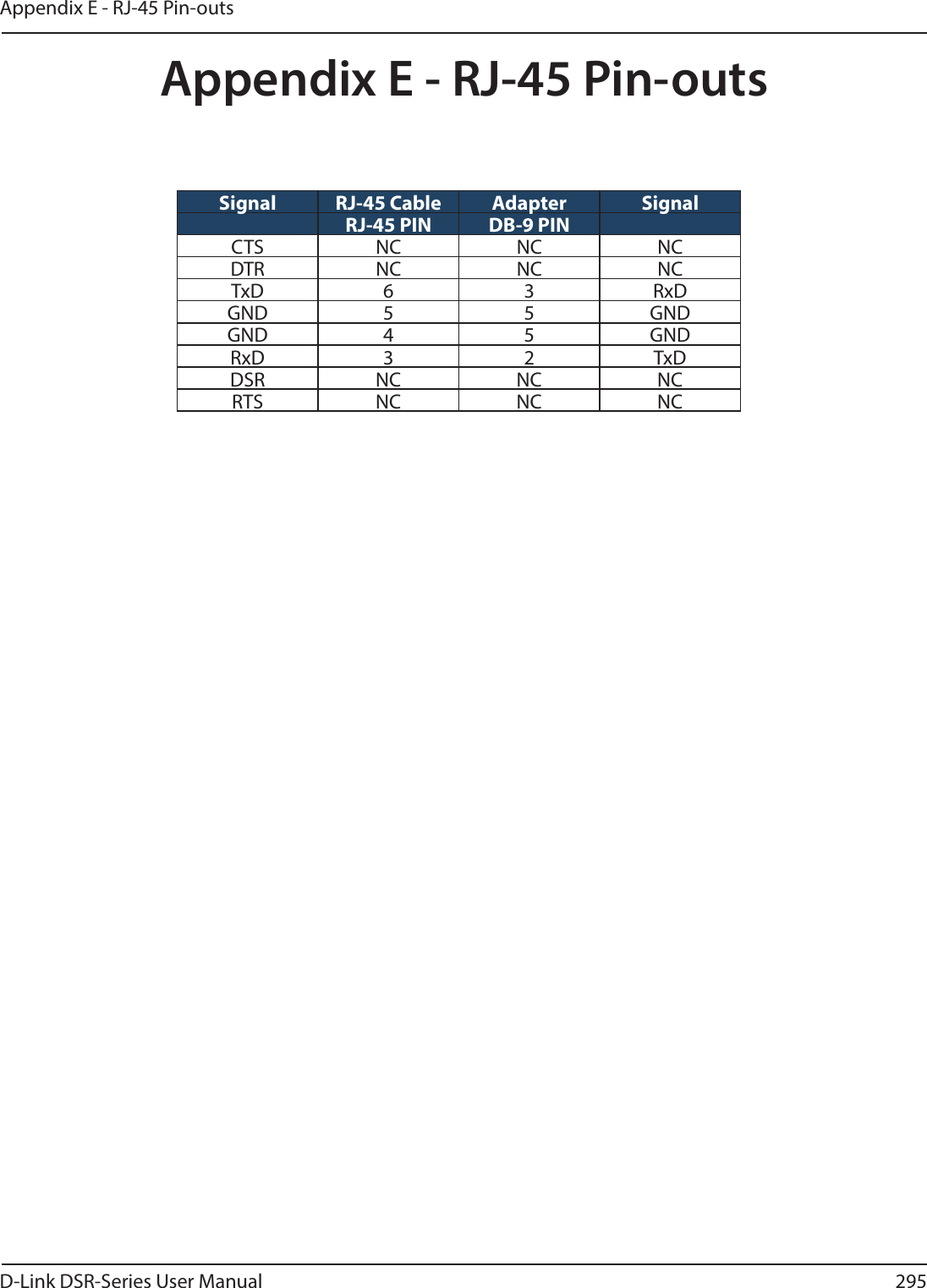
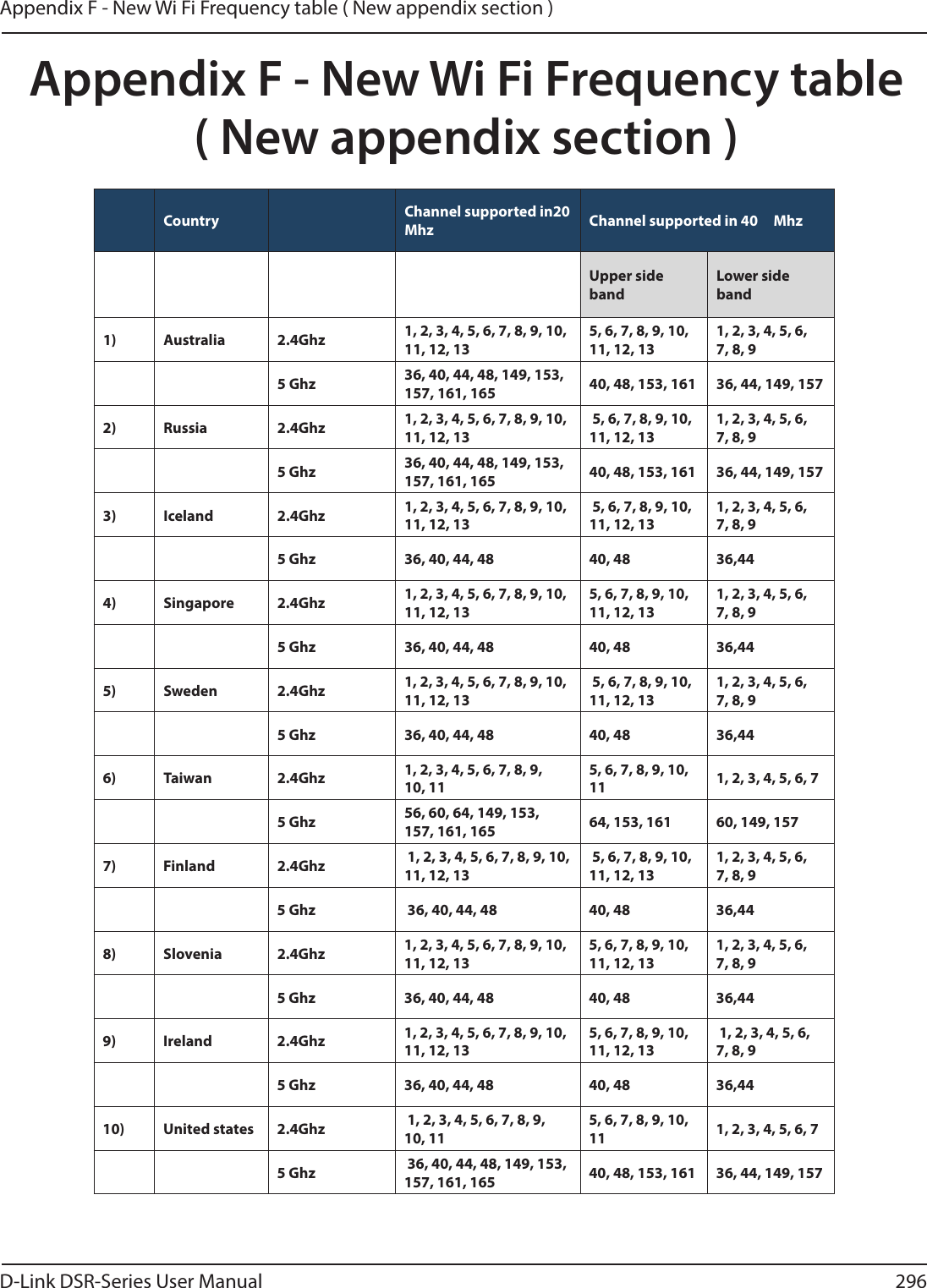
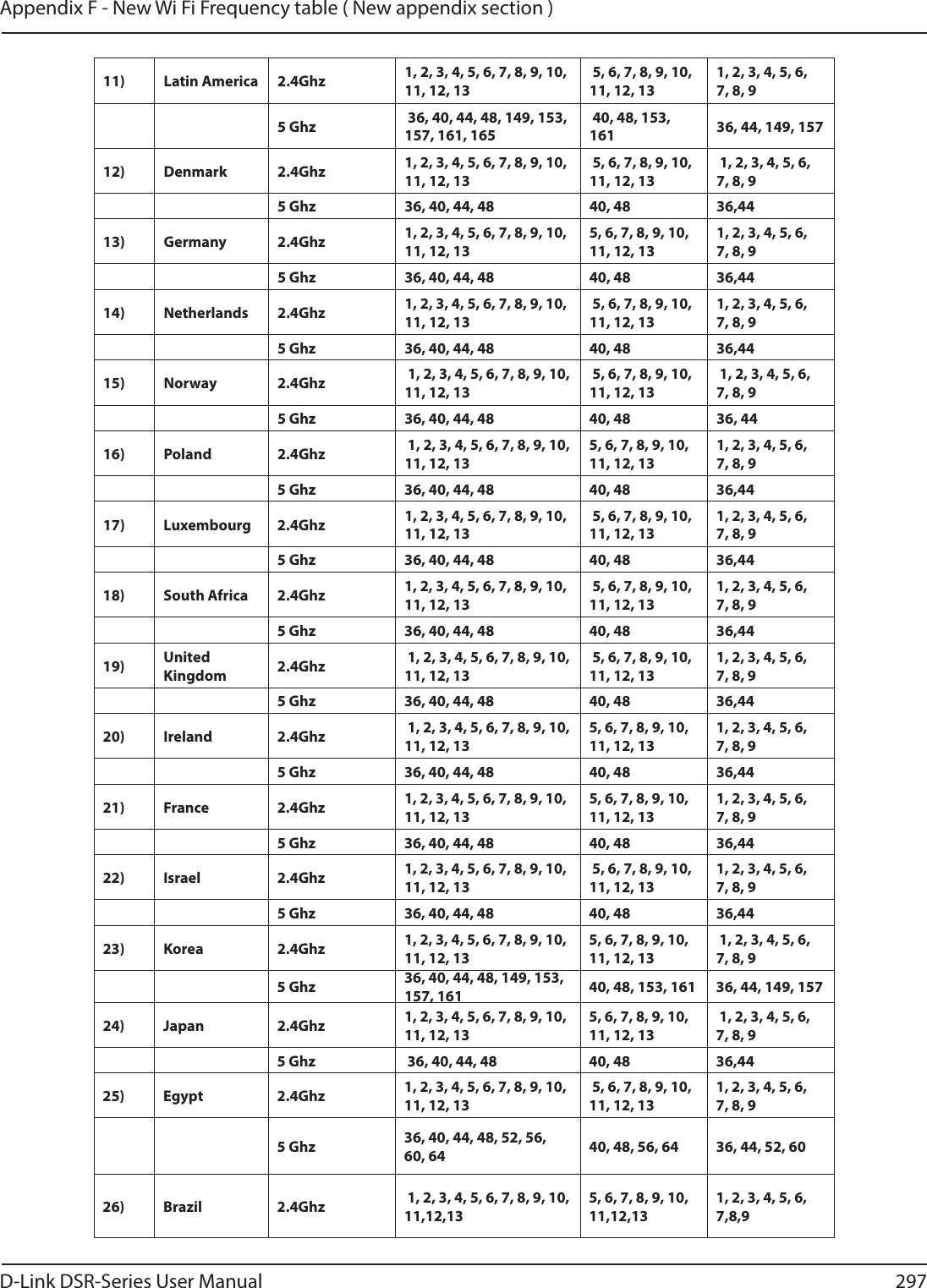
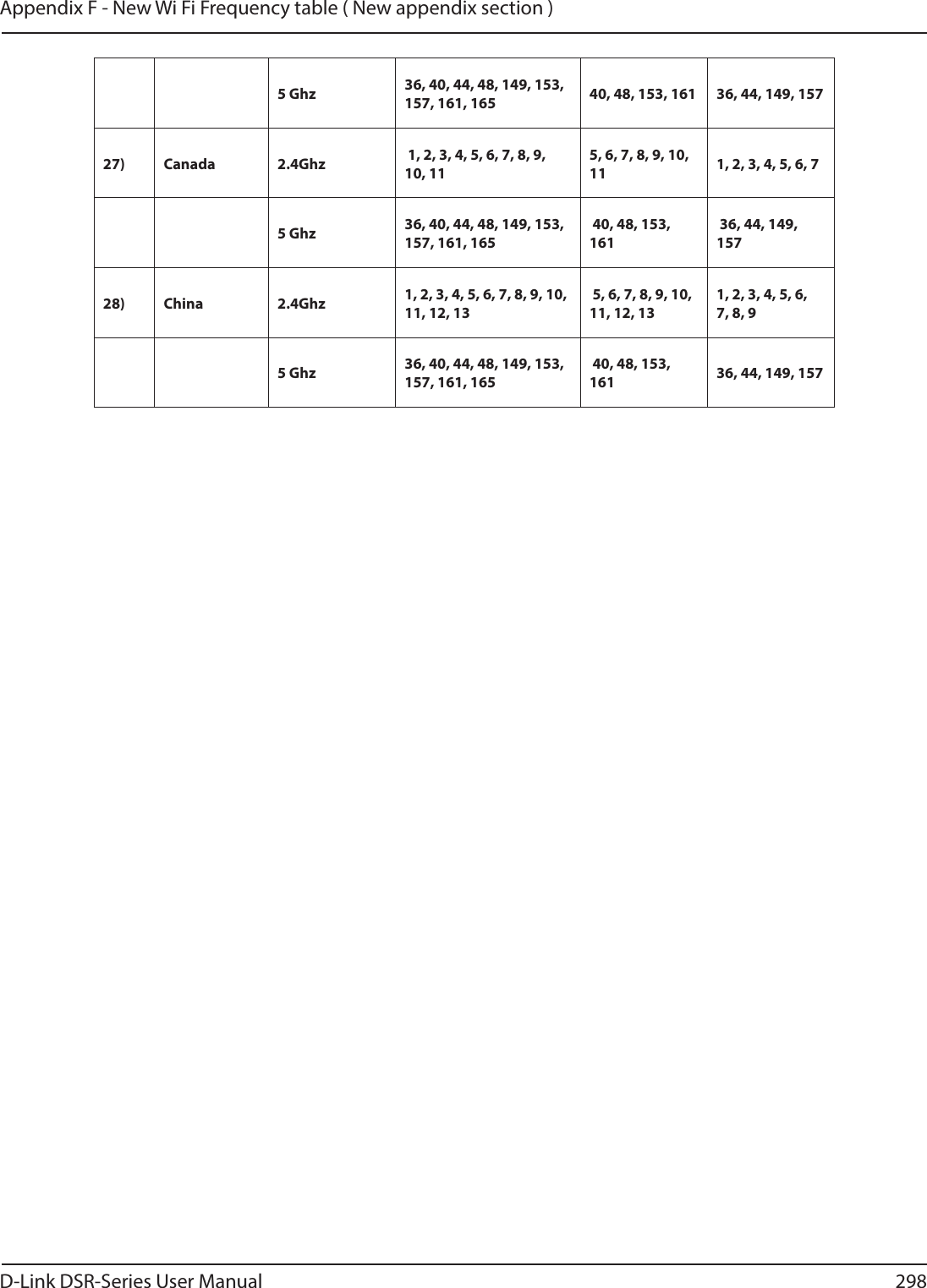
![D-Link DSR-Series User Manual 302Appendix G - Product StatementČesky [Czech][D-Link Corporation] tímto prohlašuje, že tento [DSR-1000N] je ve shodě se základními požadavky a dalšími příslušnými ustanoveními směrnice 1999/5/ES.Dansk [Danish]Undertegnede [D-Link Corporation] erklærer herved, at følgende udstyr [DSR-1000N] overholder de væsentlige krav og øvrige relevante krav i direktiv 1999/5/EF.Deutsch [German]Hiermit erklärt [D-Link Corporation], dass sich das Gerät [DSR-1000N] in Übereinstimmung mit den grundlegenden Anforderungen und den übrigen einschlägigen Bestimmungen der Richtlinie 1999/5/EG bendet.Eesti [Estonian]Käesolevaga kinnitab [D-Link Corporation] seadme [DSR-1000N] vastavust direktiivi 1999/5/EÜ põhinõuetele ja nimetatud direktiivist tulenevatele teistele asjakohastele sätetele.English Hereby, [D-Link Corporation], declares that this [DSR-1000N] is in compliance with the essential requirements and other relevant provisions of Directive 1999/5/EC.Español [Spanish]Por medio de la presente [D-Link Corporation] declara que el [DSR-1000N] cumple con los requisitos esenciales y cualesquiera otras disposiciones aplicables o exigibles de la Directiva 1999/5/CE.Ελληνική [Greek]ΜΕ ΤΗΝ ΠΑΡΟΥΣΑ [D-Link Corporation] ΗΛΝΕΙ ΟΤΙ [DSR-1000N] ΣΥΜΜΟΡΦΝΕΤΑΙ ΠΡΟΣ ΤΙΣ ΟΥΣΙΕΙΣ ΑΠΑΙΤΗΣΕΙΣ ΚΑΙ ΤΙΣ ΛΟΙΠΕΣ ΣΧΕΤΙΚΕΣ ΙΑΤΑΞΕΙΣ ΤΗΣ ΟΗΓΙΑΣ 1999/5/ΕΚ.Français [French]Par la présente [D-Link Corporation] déclare que l’appareil [DSR-1000N] est conforme aux exigences essentielles et aux autres dispositions pertinentes de la directive 1999/5/CE.Italiano [Italian]Con la presente [D-Link Corporation] dichiara che questo [DSR-1000N] è conforme ai requisiti essenziali ed alle altre disposizioni pertinenti stabilite dalla direttiva 1999/5/CE.Latviski [Latvian]Ar šo [D-Link Corporation] deklarē, ka [DSR-1000N] atbilst Direktīvas 1999/5/EK būtiskajām prasībām un citiem ar to saistītajiem noteikumiem.Lietuvių [Lithuanian] Šiuo [D-Link Corporation] deklaruoja, kad šis [DSR-1000N] atitinka esminius reikalavimus ir kitas 1999/5/EB Direktyvos nuostatas.Nederlands [Dutch]Hierbij verklaart [D-Link Corporation] dat het toestel [DSR-1000N] in overeenstemming is met de essentiële eisen en de andere relevante bepalingen van richtlijn 1999/5/EG.Malti [Maltese]Hawnhekk, [D-Link Corporation], jiddikjara li dan [DSR-1000N] jikkonforma mal-ħtiġijiet essenzjali u ma provvedimenti oħrajn relevanti li hemm d-Dirrettiva 1999/5/EC.Magyar [Hungarian]Alulírott, [D-Link Corporation] nyilatkozom, hogy a [DSR-1000N] megfelel a vonatkozó alapvetõ követelményeknek és az 1999/5/EC irányelv egyéb elõírásainak.Polski [Polish]Niniejszym [D-Link Corporation] oświadcza, że [DSR-1000N] jest zgodny z zasadniczymi wymogami oraz pozostałymi stosownymi postanowieniami Dyrektywy 1999/5/EC.](https://usermanual.wiki/D-Link/SR500ACA1/User-Guide-2623752-Page-315.png)
![D-Link DSR-Series User Manual 303Appendix G - Product StatementPortuguês [Portuguese][D-Link Corporation] declara que este [DSR-1000N]está conforme com os requisitos essenciais e outras disposições da Directiva 1999/5/CE.Slovensko [Slovenian][D-Link Corporation] izjavlja, da je ta [DSR-1000N] v skladu z bistvenimi zahtevami in ostalimi relevantnimi določili direktive 1999/5/ES.Slovensky [Slovak][D-Link Corporation] týmto vyhlasuje, že [DSR-1000N] spĺňa základné požiadavky a všetky príslušné ustanovenia Smernice 1999/5/ES.Suomi [Finnish][D-Link Corporation] vakuuttaa täten että [DSR-1000N] tyyppinen laite on direktiivin 1999/5/EY oleellisten vaatimusten ja sitä koskevien direktiivin muiden ehtojen mukainen.Svenska [Swedish]Härmed intygar [D-Link Corporation] att denna [DSR-1000N] står I överensstämmelse med de väsentliga egenskapskrav och övriga relevanta bestämmelser som framgår av direktiv 1999/5/EG.](https://usermanual.wiki/D-Link/SR500ACA1/User-Guide-2623752-Page-316.png)
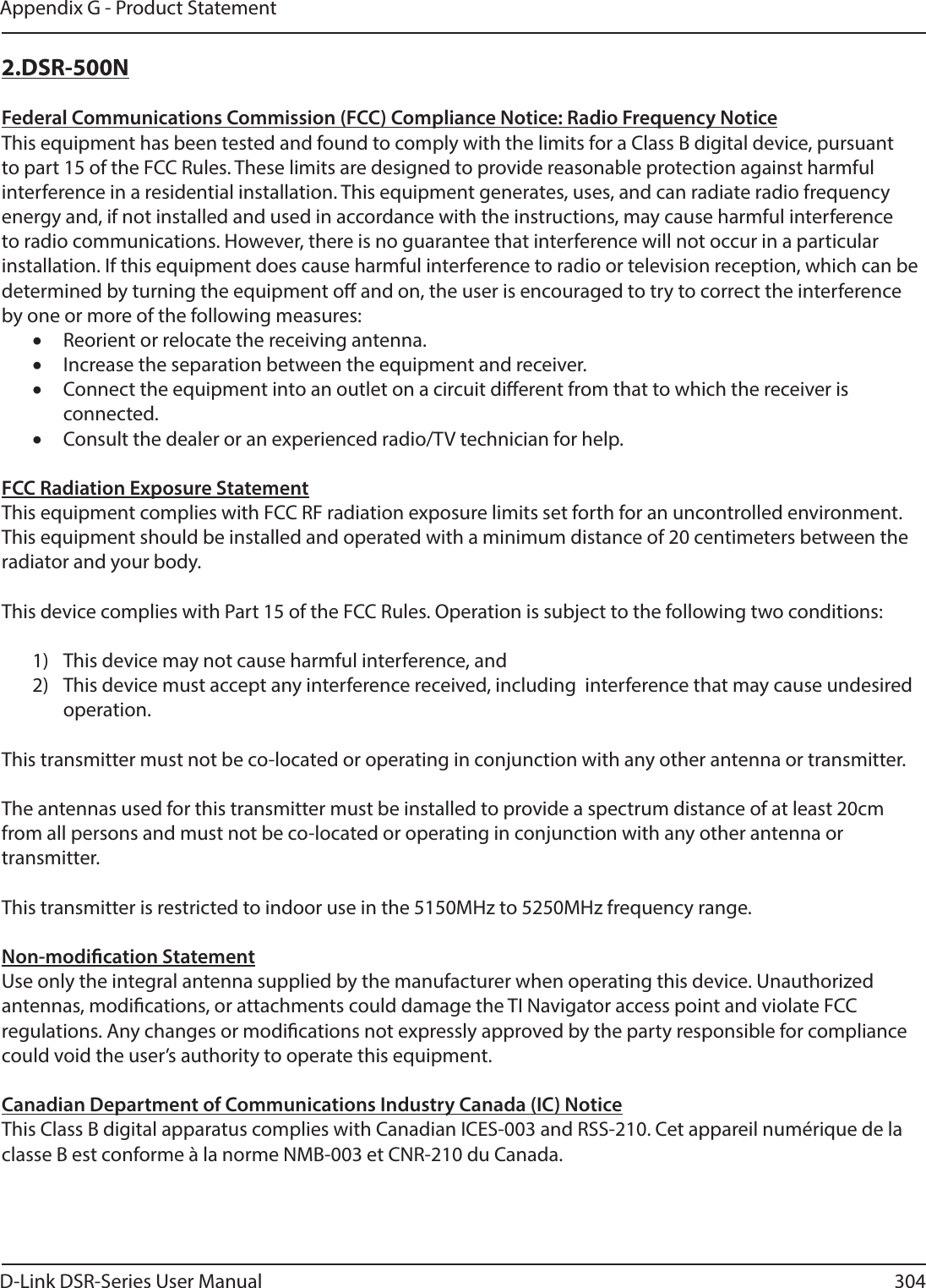
![D-Link DSR-Series User Manual 306Appendix G - Product StatementýHVN\>&]HFK@>'/LQN&RUSRUDWLRQ@WtPWRSURKODãXMHåHWHQWR>'651@MHYHVKRGČVH]iNODGQtPLSRåDGDYN\DGDOãtPLSĜtVOXãQêPLXVWDQRYHQtPLVPČUQLFH(6'DQVN>'DQLVK@8QGHUWHJQHGH>'/LQN&RUSRUDWLRQ@HUNOUHUKHUYHGDWI¡OJHQGHXGVW\U>'651@RYHUKROGHUGHYVHQWOLJHNUDYRJ¡YULJHUHOHYDQWHNUDYLGLUHNWLY()'HXWVFK>*HUPDQ@+LHUPLWHUNOlUW>'/LQN&RUSRUDWLRQ@GDVVVLFKGDV*HUlW>'651@LQhEHUHLQVWLPPXQJPLWGHQJUXQGOHJHQGHQ$QIRUGHUXQJHQXQGGHQEULJHQHLQVFKOlJLJHQ%HVWLPPXQJHQGHU5LFKWOLQLH(*EH¿QGHW(HVWL>(VWRQLDQ@.lHVROHYDJDNLQQLWDE>'/LQN&RUSRUDWLRQ@VHDGPH>'651@YDVWDYXVWGLUHNWLLYL(hS}KLQ}XHWHOHMDQLPHWDWXGGLUHNWLLYLVWWXOHQHYDWHOHWHLVWHOHDVMDNRKDVWHOHVlWHWHOH(QJOLVK +HUHE\>'/LQN&RUSRUDWLRQ@GHFODUHVWKDWWKLV>'651@LVLQFRPSOLDQFHZLWKWKHHVVHQWLDOUHTXLUHPHQWVDQGRWKHUUHOHYDQWSURYLVLRQVRI'LUHFWLYH(&(VSDxRO>6SDQLVK@3RUPHGLRGHODSUHVHQWH>'/LQN&RUSRUDWLRQ@GHFODUDTXHHO>'651@FXPSOHFRQORVUHTXLVLWRVHVHQFLDOHV\FXDOHVTXLHUDRWUDVGLVSRVLFLRQHVDSOLFDEOHVRH[LJLEOHVGHOD'LUHFWLYD&(ǼȜȜȘȞȚțȒ>*UHHN@ȂǼȉǾȃȆǹȇȅȊȈǹ>'/LQN&RUSRUDWLRQ@ǻǾȁȍȃǼǿȅȉǿ>'651@ȈȊȂȂȅȇĭȍȃǼȉǹǿȆȇȅȈȉǿȈȅȊȈǿȍǻǼǿȈǹȆǹǿȉǾȈǼǿȈȀǹǿȉǿȈȁȅǿȆǼȈȈȋǼȉǿȀǼȈǻǿǹȉǹȄǼǿȈȉǾȈȅǻǾīǿǹȈǼȀ)UDQoDLV>)UHQFK@3DUODSUpVHQWH>'/LQN&RUSRUDWLRQ@GpFODUHTXHO¶DSSDUHLO>'651@HVWFRQIRUPHDX[H[LJHQFHVHVVHQWLHOOHVHWDX[DXWUHVGLVSRVLWLRQVSHUWLQHQWHVGHODGLUHFWLYH&(,WDOLDQR>,WDOLDQ@&RQODSUHVHQWH>'/LQN&RUSRUDWLRQ@GLFKLDUDFKHTXHVWR>'651@qFRQIRUPHDLUHTXLVLWLHVVHQ]LDOLHGDOOHDOWUHGLVSRVL]LRQLSHUWLQHQWLVWDELOLWHGDOODGLUHWWLYD&(/DWYLVNL>/DWYLDQ@$UãR>'/LQN&RUSRUDWLRQ@GHNODUƝND>'651@DWELOVW'LUHNWƯYDV(.EnjWLVNDMƗPSUDVƯEƗPXQFLWLHPDUWRVDLVWƯWDMLHPQRWHLNXPLHP/LHWXYLǐ>/LWKXDQLDQ@âLXR>'/LQN&RUSRUDWLRQ@GHNODUXRMDNDGãLV>'651@DWLWLQNDHVPLQLXVUHLNDODYLPXVLUNLWDV(%'LUHNW\YRVQXRVWDWDV1HGHUODQGV>'XWFK@+LHUELMYHUNODDUW>'/LQN&RUSRUDWLRQ@GDWKHWWRHVWHO>'651@LQRYHUHHQVWHPPLQJLVPHWGHHVVHQWLsOHHLVHQHQGHDQGHUHUHOHYDQWHEHSDOLQJHQYDQULFKWOLMQ(*0DOWL>0DOWHVH@+DZQKHNN>'/LQN&RUSRUDWLRQ@MLGGLNMDUDOLGDQ>'651@MLNNRQIRUPDPDOƫWLƥLMLHWHVVHQ]MDOLXPDSURYYHGLPHQWLRƫUDMQUHOHYDQWLOLKHPP¿G'LUUHWWLYD(&0DJ\DU>+XQJDULDQ@$OXOtURWW>'/LQN&RUSRUDWLRQ@Q\LODWNR]RPKRJ\D>'651@PHJIHOHODYRQDWNR]yDODSYHW}N|YHWHOPpQ\HNQHNpVD](&LUiQ\HOYHJ\pEHO}tUiVDLQDN3ROVNL>3ROLVK@1LQLHMV]\P>'/LQN&RUSRUDWLRQ@RĞZLDGF]DĪH>'651@MHVW]JRGQ\]]DVDGQLF]\PLZ\PRJDPLRUD]SR]RVWDá\PLVWRVRZQ\PLSRVWDQRZLHQLDPL'\UHNW\Z\(&](https://usermanual.wiki/D-Link/SR500ACA1/User-Guide-2623752-Page-319.png)
![D-Link DSR-Series User Manual 307Appendix G - Product Statement3RUWXJXrV>3RUWXJXHVH@>'/LQN&RUSRUDWLRQ@GHFODUDTXHHVWH>'651@HVWiFRQIRUPHFRPRVUHTXLVLWRVHVVHQFLDLVHRXWUDVGLVSRVLo}HVGD'LUHFWLYD&(6ORYHQVNR>6ORYHQLDQ@>'/LQN&RUSRUDWLRQ@L]MDYOMDGDMHWD>'651@YVNODGX]ELVWYHQLPL]DKWHYDPLLQRVWDOLPLUHOHYDQWQLPLGRORþLOLGLUHNWLYH(66ORYHQVN\>6ORYDN@>'/LQN&RUSRUDWLRQ@WêPWRY\KODVXMHåH>'651@VSĎĖD]iNODGQpSRåLDGDYN\DYãHWN\SUtVOXãQpXVWDQRYHQLD6PHUQLFH(66XRPL>)LQQLVK@>'/LQN&RUSRUDWLRQ@YDNXXWWDDWlWHQHWWl>'651@W\\SSLQHQODLWHRQGLUHNWLLYLQ(<ROHHOOLVWHQYDDWLPXVWHQMDVLWlNRVNHYLHQGLUHNWLLYLQPXLGHQHKWRMHQPXNDLQHQ6YHQVND>6ZHGLVK@+lUPHGLQW\JDU>'/LQN&RUSRUDWLRQ@DWWGHQQD>'651@VWnU,|YHUHQVVWlPPHOVHPHGGHYlVHQWOLJDHJHQVNDSVNUDYRFK|YULJDUHOHYDQWDEHVWlPPHOVHUVRPIUDPJnUDYGLUHNWLY(*](https://usermanual.wiki/D-Link/SR500ACA1/User-Guide-2623752-Page-320.png)
![D-Link DSR-Series User Manual 308Appendix G - Product Statement3.DSR-250NFederal Communication Commission Interference StatementThis equipment has been tested and found to comply with the limits for a Class B digital device, pursuant to Part 15 of the FCC Rules. These limits are designed to provide reasonable protection against harmful interference in a residential installation. This equipment generates, uses and can radiate radio frequency energy and, if not installed and used in accordance with the instructions, may cause harmful interference to radio communications. However, there is no guarantee that interference will not occur in a particular installation. If this equipment does cause harmful interference to radio or television reception, which can be determined by turning the equipment o and on, the user is encouraged to try to correct the interference by one of the following measures:x Reorient or relocate the receiving antenna.x Increase the separation between the equipment and receiver.x Connect the equipment into an outlet on a circuit dierent from that to which the receiver is connected.x Consult the dealer or an experienced radio/TV technician for help.FCC Caution: Any changes or modications not expressly approved by the party responsible for compliance could void the user’s authority to operate this equipment.This device complies with Part 15 of the FCC Rules. Operation is subject to the following two conditions: (1) This device may not cause harmful interference, and (2) this device must accept any interference received, including interference that may cause undesired operation.RSS-GEN 7.1.4:User Manual for Transmitters with Detachable AntennasThe user manual of transmitter devices equipped with detachable antennas shall contain the following information in a conspicuous location:This device has been designed to operate with the antennas listed below, and having a maximum gain of [1.8] dB. Antennas not included in this list or having a gain greater than [1.8] dB are strictly prohibited for use with this device. The required antenna impedance is [50] ohms.RSS-GEN 7.1.5To reduce potential radio interference to other users, the antenna type and its gain should be so chosen that the equivalent isotropically radiated power (e.i.r.p.) is not more than that permitted for successful communication.Le présent appareil est conforme aux CNR d’Industrie Canada applicables aux appareils radio exempts de licence. L’exploitation est autorisée aux deux conditions suivantes: (1) l’appareil ne doit pas produire de brouillage, et (2) l’utilisateur de l’appareil doit accepter tout brouillage radioélectrique subi, même si le brouillage est susceptible d’en comSpromettre le fonctionnement.Is herewith conrmed to comply with the requirements set out in the Council Directive on the Approximation of the Laws of the Member States relating to Electromagnetic Compatibility (2004/108/](https://usermanual.wiki/D-Link/SR500ACA1/User-Guide-2623752-Page-321.png)
![D-Link DSR-Series User Manual 313Appendix G - Product StatementČesky [Czech][Jméno výrobce] tímto prohlašuje, že tento [typ zařízení] je ve shodě se základními požadavky a dalšími příslušnými ustanoveními směrnice 1999/5/ES.Dansk [Danish]Undertegnede [fabrikantens navn] erklærer herved, at følgende udstyr [udstyrets typebetegnelse] overholder de væsentlige krav og øvrige relevante krav i direktiv 1999/5/EF.Deutsch [German]Hiermit erklärt [Name des Herstellers], dass sich das Gerät [Gerätetyp] in Übereinstimmung mit den grundlegenden Anforderungen und den übrigen einschlägigen Bestimmungen der Richtlinie 1999/5/EG bendet.Eesti [Estonian]Käesolevaga kinnitab [tootja nimi = name of manufacturer] seadme [seadme tüüp = type of equipment] vastavust direktiivi 1999/5/EÜ põhinõuetele ja nimetatud direktiivist tulenevatele teistele asjakohastele sätetele.English Hereby, [name of manufacturer], declares that this [type of equipment] is in compliance with the essential requirements and other relevant provisions of Directive 1999/5/EC.Español [Spanish]Por medio de la presente [nombre del fabricante] declara que el [clase de equipo] cumple con los requisitos esenciales y cualesquiera otras disposiciones aplicables o exigibles de la Directiva 1999/5/CE.Ελληνική [Greek]ΜΕ ΤΗΝ ΠΑΡΟΥΣΑ [name of manufacturer] ΗΛΝΕΙ ΟΤΙ [type of equipment] ΣΥΜΜΟΡΦΝΕΤΑΙ ΠΡΟΣ ΤΙΣ ΟΥΣΙΕΙΣ ΑΠΑΙΤΗΣΕΙΣ ΚΑΙ ΤΙΣ ΛΟΙΠΕΣ ΣΧΕΤΙΚΕΣ ΙΑΤΑΞΕΙΣ ΤΗΣ ΟΗΓΙΑΣ 1999/5/ΕΚ.Français [French]Par la présente [nom du fabricant] déclare que l’appareil [type d’appareil] est conforme aux exigences essentielles et aux autres dispositions pertinentes de la directive 1999/5/CE.Italiano [Italian]Con la presente [nome del costruttore] dichiara che questo [tipo di apparecchio] è conforme ai requisiti essenziali ed alle altre disposizioni pertinenti stabilite dalla direttiva 1999/5/CE.Latviski [Latvian]Ar šo [name of manufacturer / izgatavotāja nosaukums] deklarē, ka [type of equipment / iekārtas tips] atbilst Direktīvas 1999/5/EK būtiskajām prasībām un citiem ar to saistītajiem noteikumiem.Lietuvių [Lithuanian] Šiuo [manufacturer name] deklaruoja, kad šis [equipment type] atitinka esminius reikalavimus ir kitas 1999/5/EB Direktyvos nuostatas.Nederlands [Dutch]Hierbij verklaart [naam van de fabrikant] dat het toestel [type van toestel] in overeenstemming is met de essentiële eisen en de andere relevante bepalingen van richtlijn 1999/5/EG.Malti [Maltese]Hawnhekk, [isem tal-manifattur], jiddikjara li dan [il-mudel tal-prodott] jikkonforma mal-ħtiġijiet essenzjali u ma provvedimenti oħrajn relevanti li hemm d-Dirrettiva 1999/5/EC.Magyar [Hungarian]Alulírott, [gyártó neve] nyilatkozom, hogy a [... típus] megfelel a vonatkozó alapvetõ követelményeknek és az 1999/5/EC irányelv egyéb elõírásainak.Polski [Polish]Niniejszym [nazwa producenta] oświadcza, że [nazwa wyrobu] jest zgodny z zasadniczymi wymogami oraz pozostałymi stosownymi postanowieniami Dyrektywy 1999/5/EC.Português [Portuguese][Nome do fabricante] declara que este [tipo de equipamento] está conforme com os requisitos essenciais e outras disposições da Directiva 1999/5/CE.Slovensko [Slovenian][Ime proizvajalca] izjavlja, da je ta [tip opreme] v skladu z bistvenimi zahtevami in ostalimi relevantnimi določili direktive 1999/5/ES.Slovensky [Slovak][Meno výrobcu] týmto vyhlasuje, že [typ zariadenia] spĺňa základné požiadavky a všetky príslušné ustanovenia Smernice 1999/5/ES.Suomi [Finnish][Valmistaja=manufacturer] vakuuttaa täten että [type of equipment = laitteen tyyppimerkintä] tyyppinen laite on direktiivin 1999/5/EY oleellisten vaatimusten ja sitä koskevien direktiivin muiden ehtojen mukainen.Svenska [Swedish]Härmed intygar [företag] att denna [utrustningstyp] står I överensstämmelse med de väsentliga egenskapskrav och övriga relevanta bestämmelser som framgår av direktiv 1999/5/EG.](https://usermanual.wiki/D-Link/SR500ACA1/User-Guide-2623752-Page-326.png)