D Link WL6700APA1 802.11n Dual-band Unified Access Point User Manual
D Link Corporation 802.11n Dual-band Unified Access Point
UserManual.wiki
>
D Link
>
WL6700APA1 User Manual
User manual
Navigation menu
Upload a User Manual
Namespaces
Wiki Guide
HTML
PDF
Info
Views
User Manual
Discussion / Help
Navigation
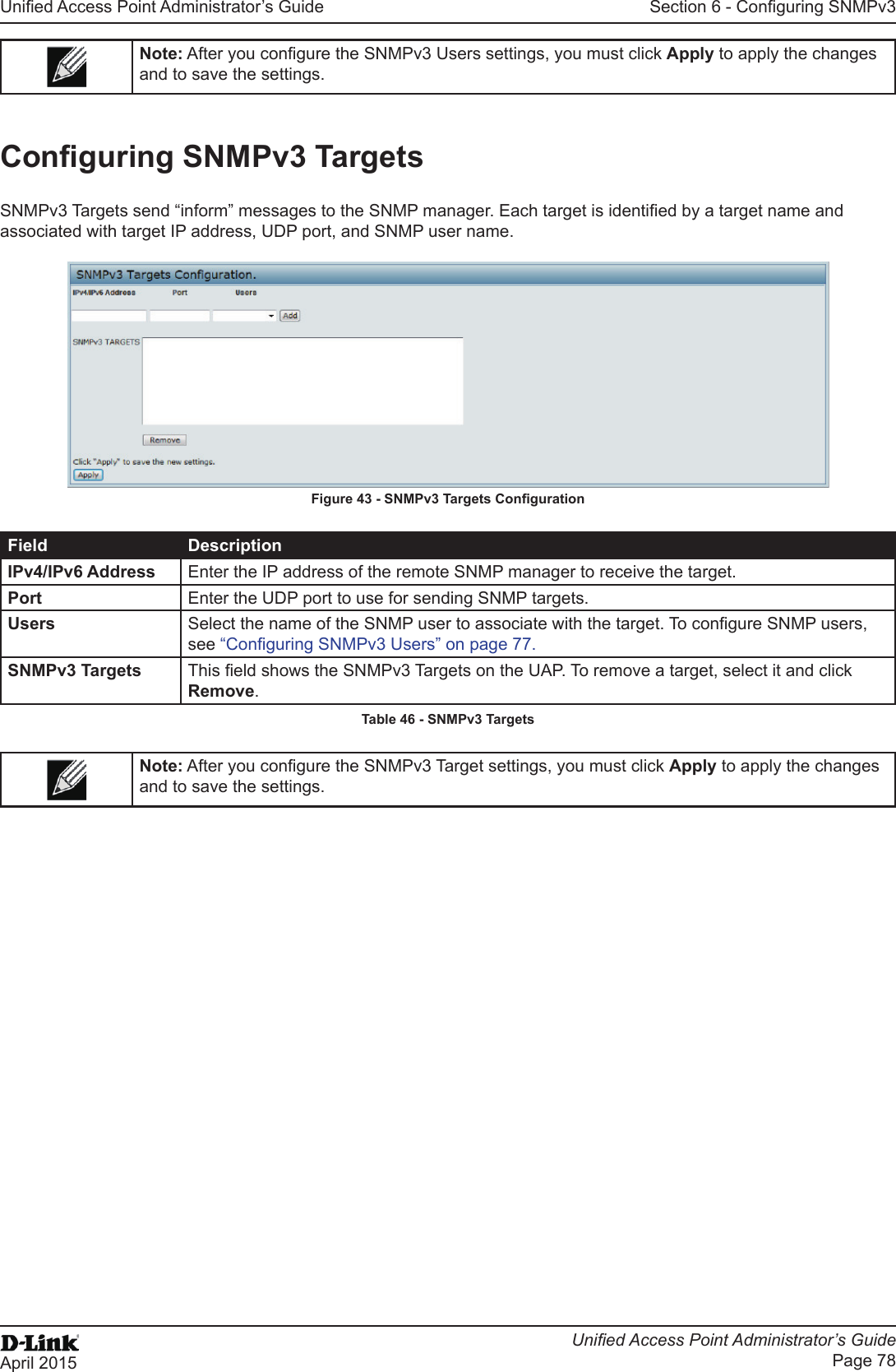
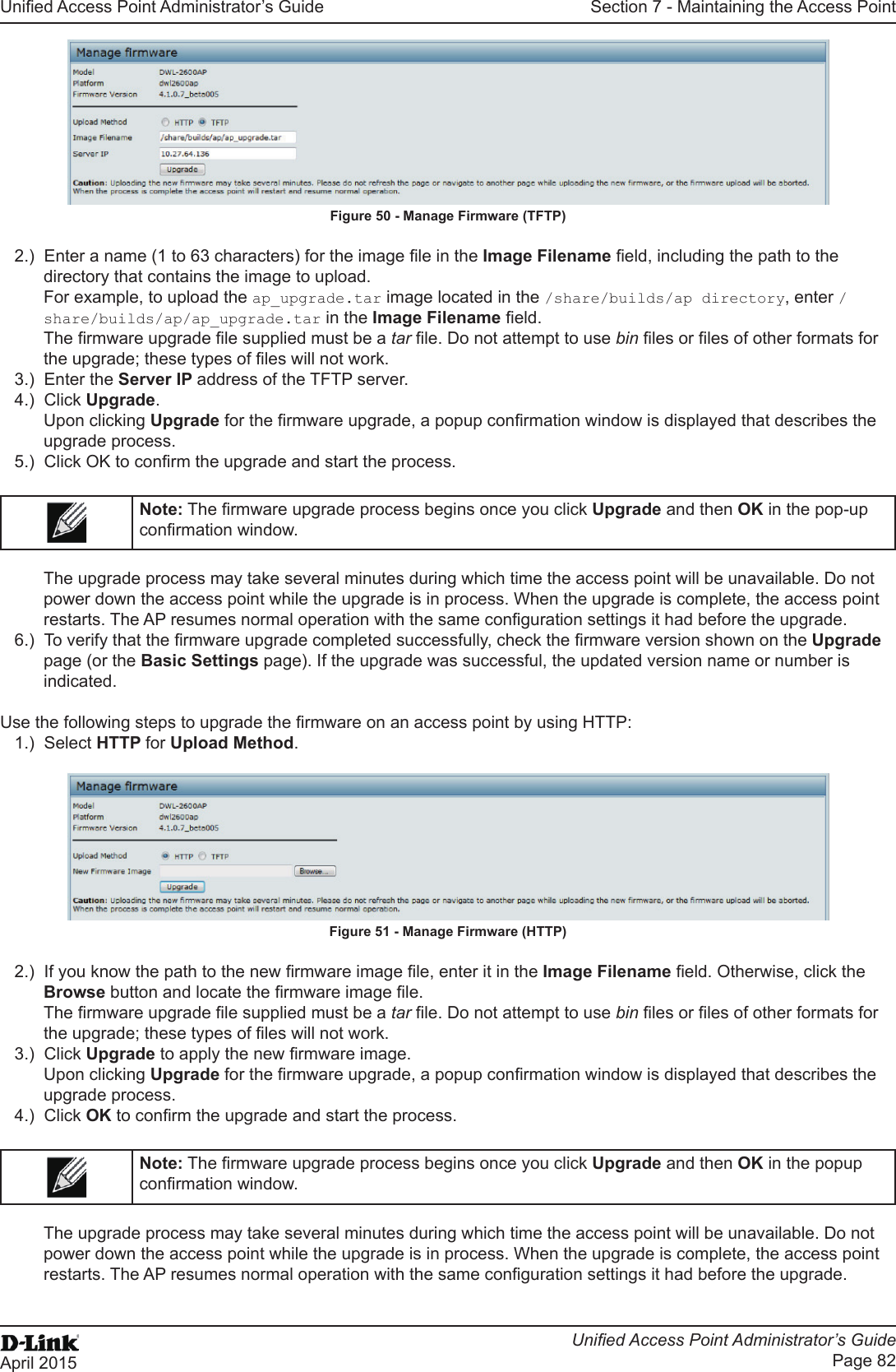
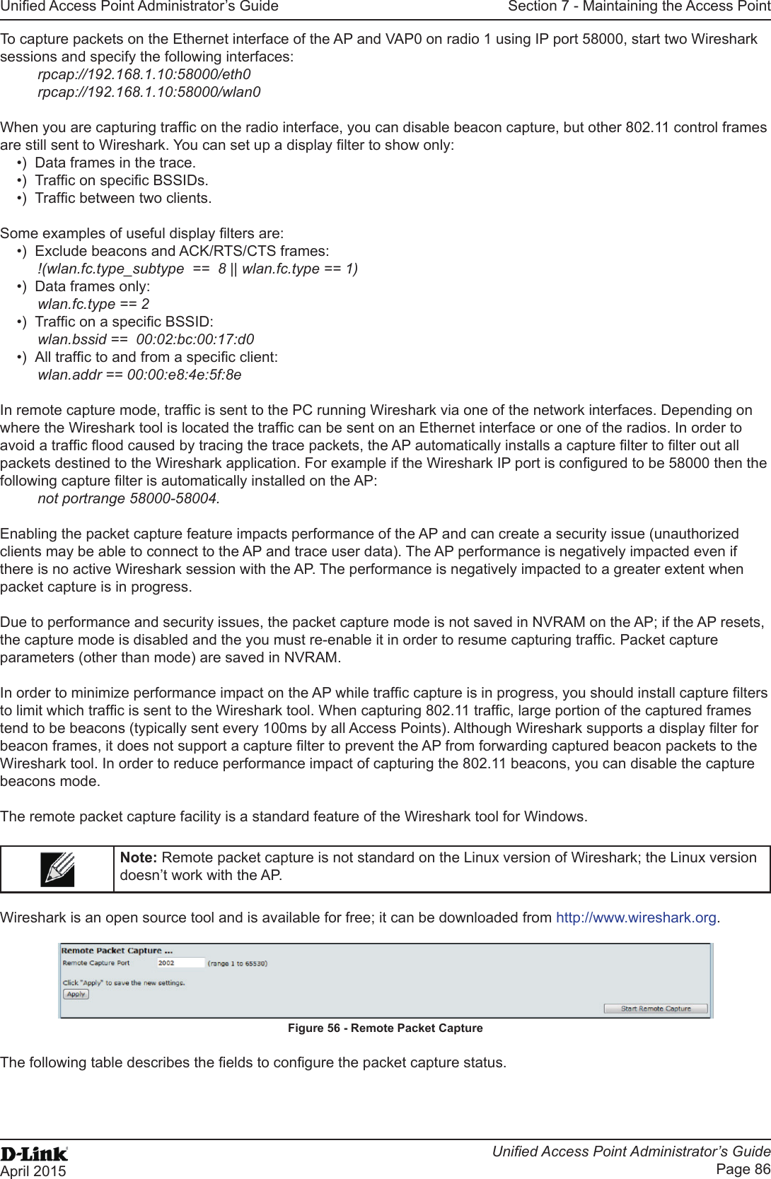
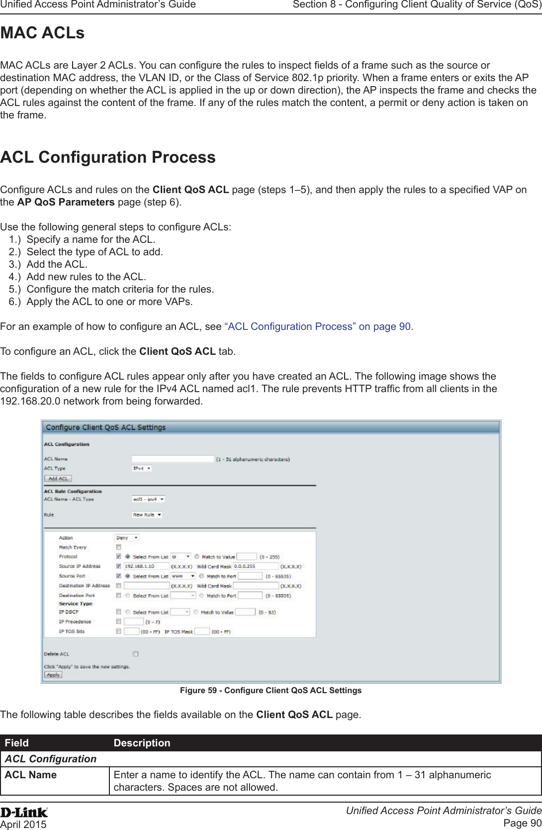
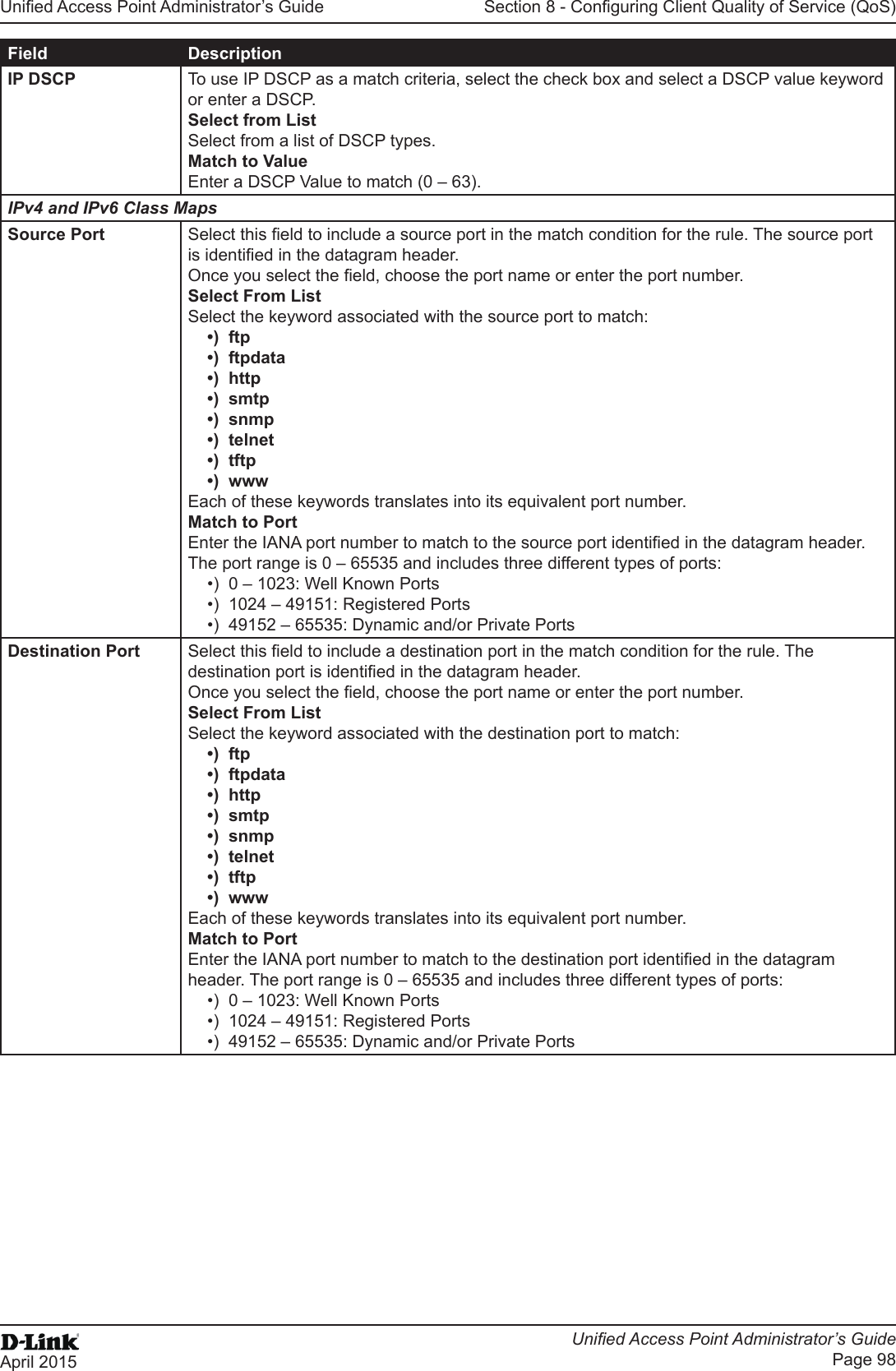
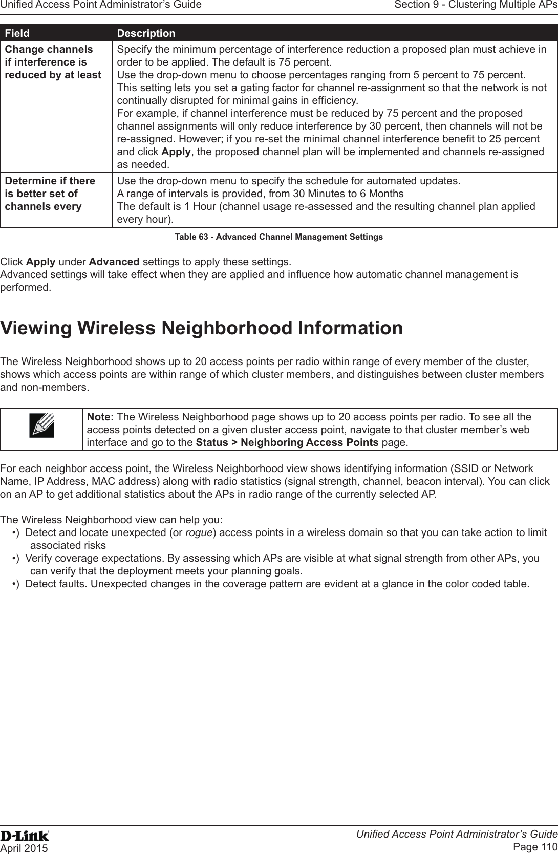
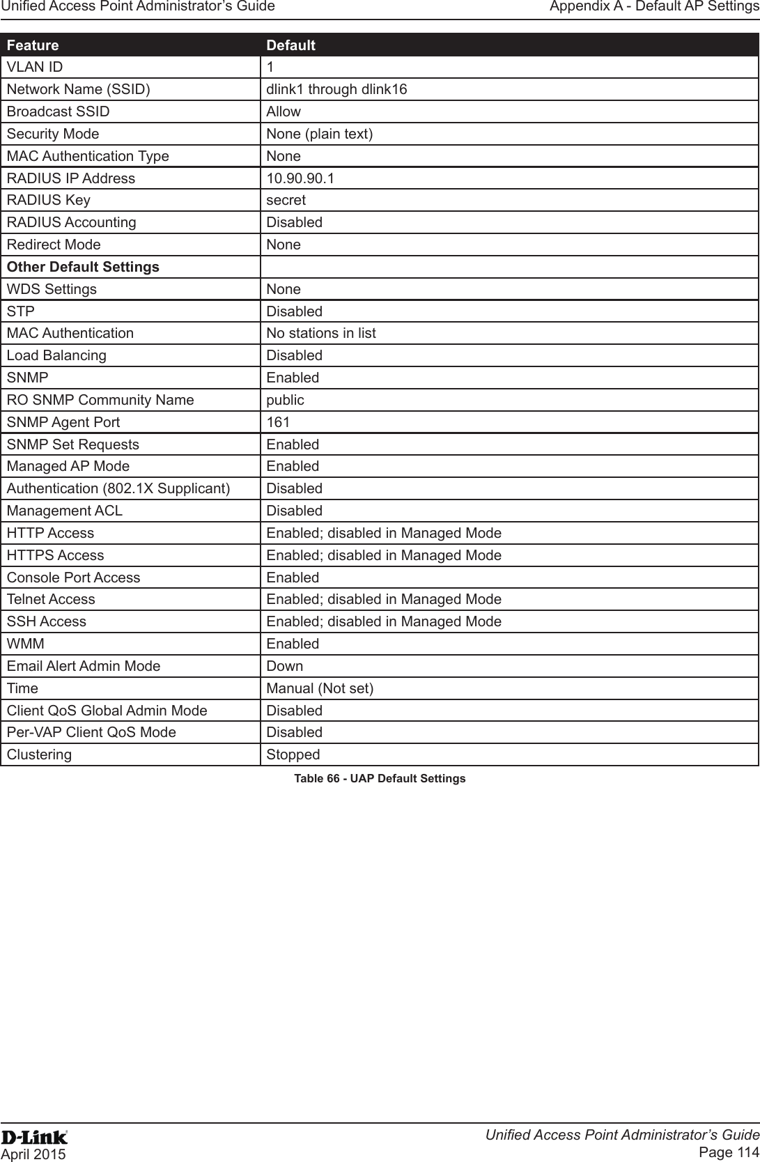
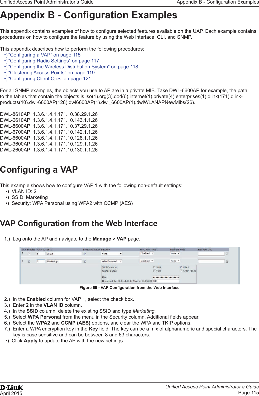
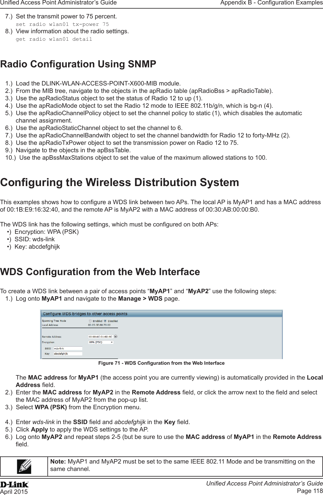
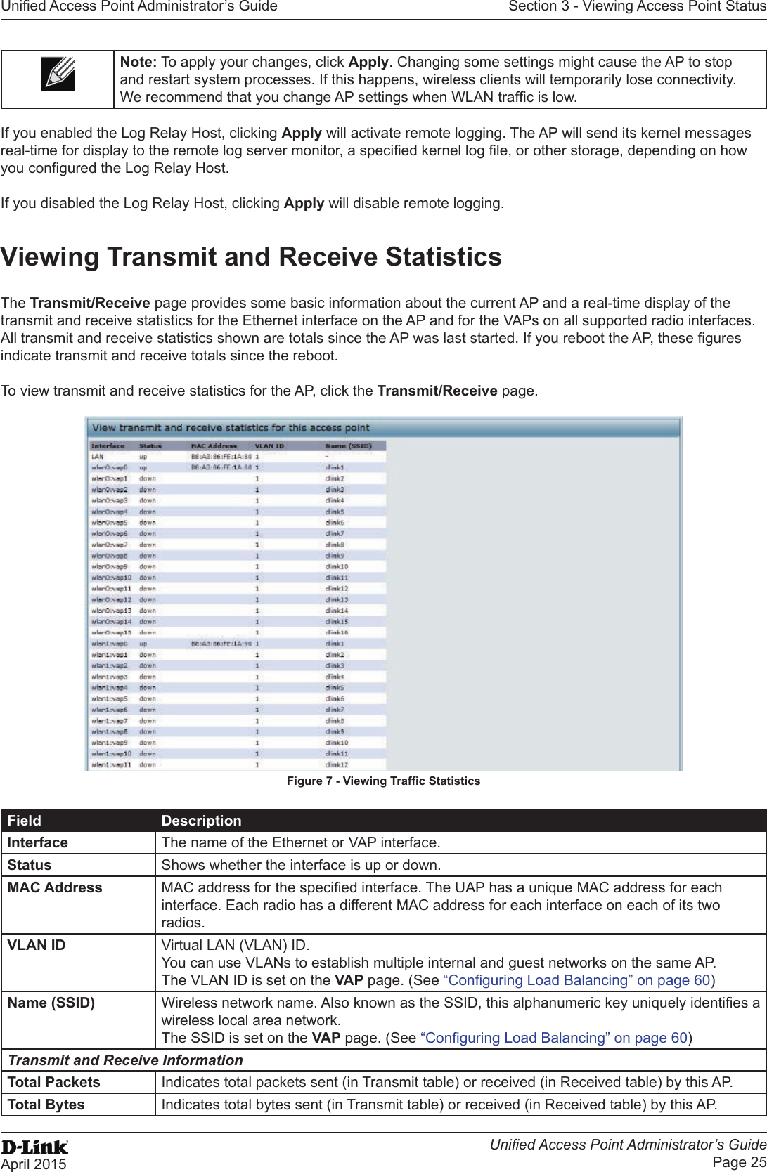
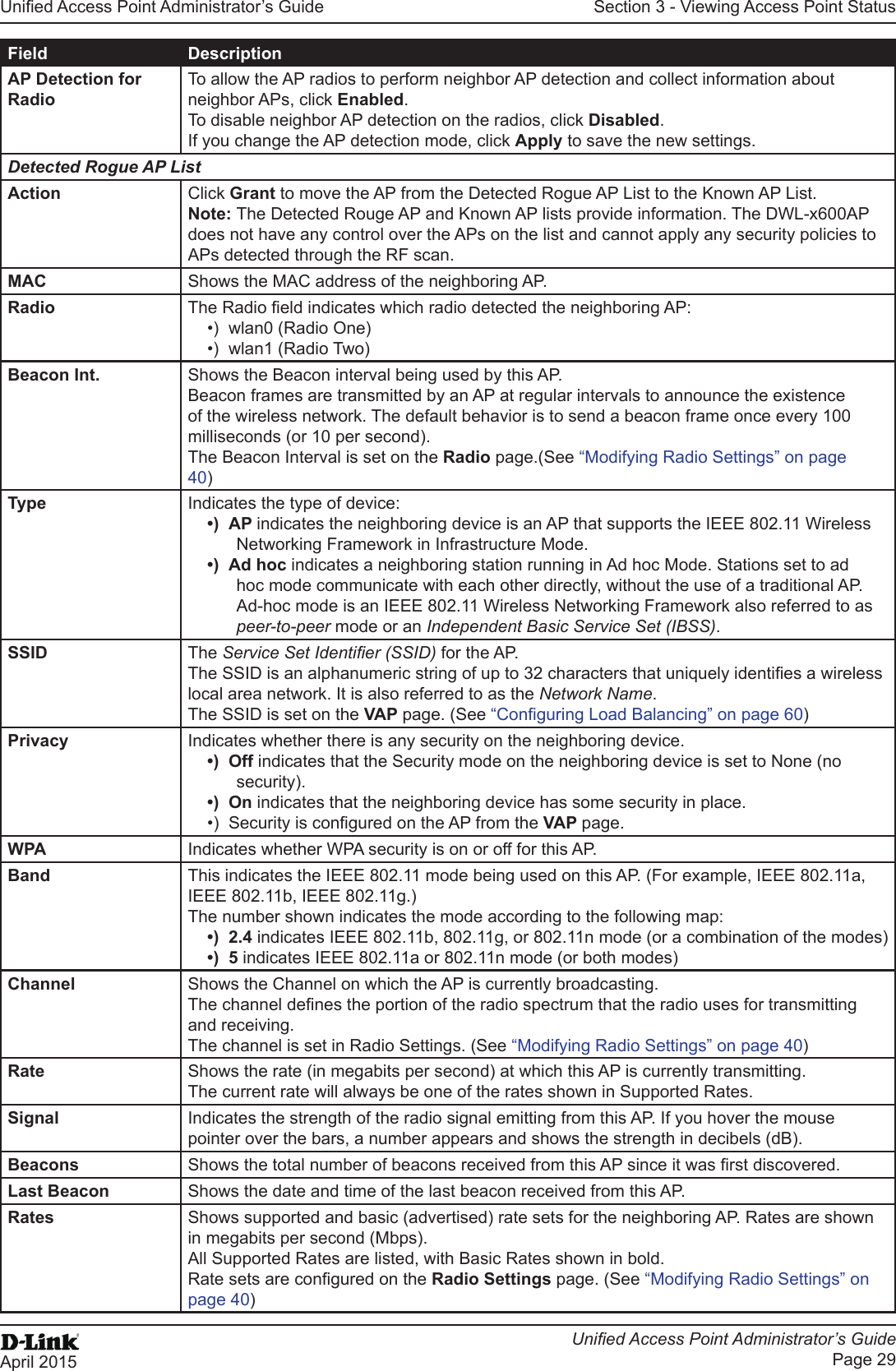
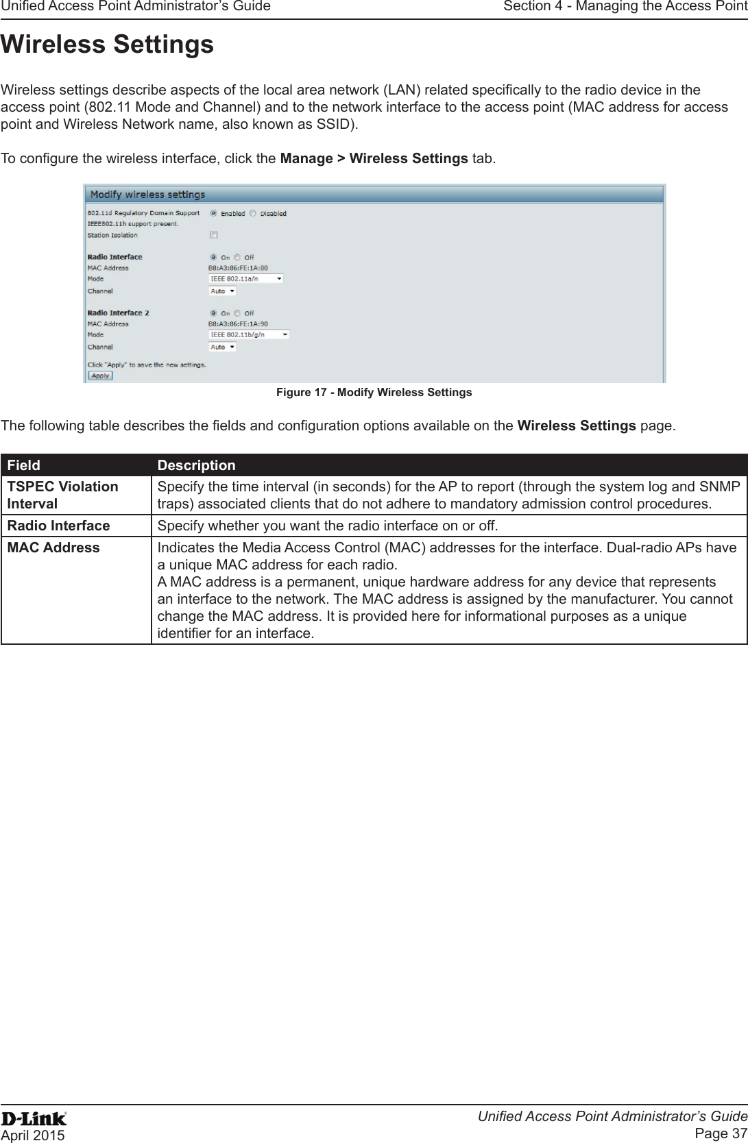
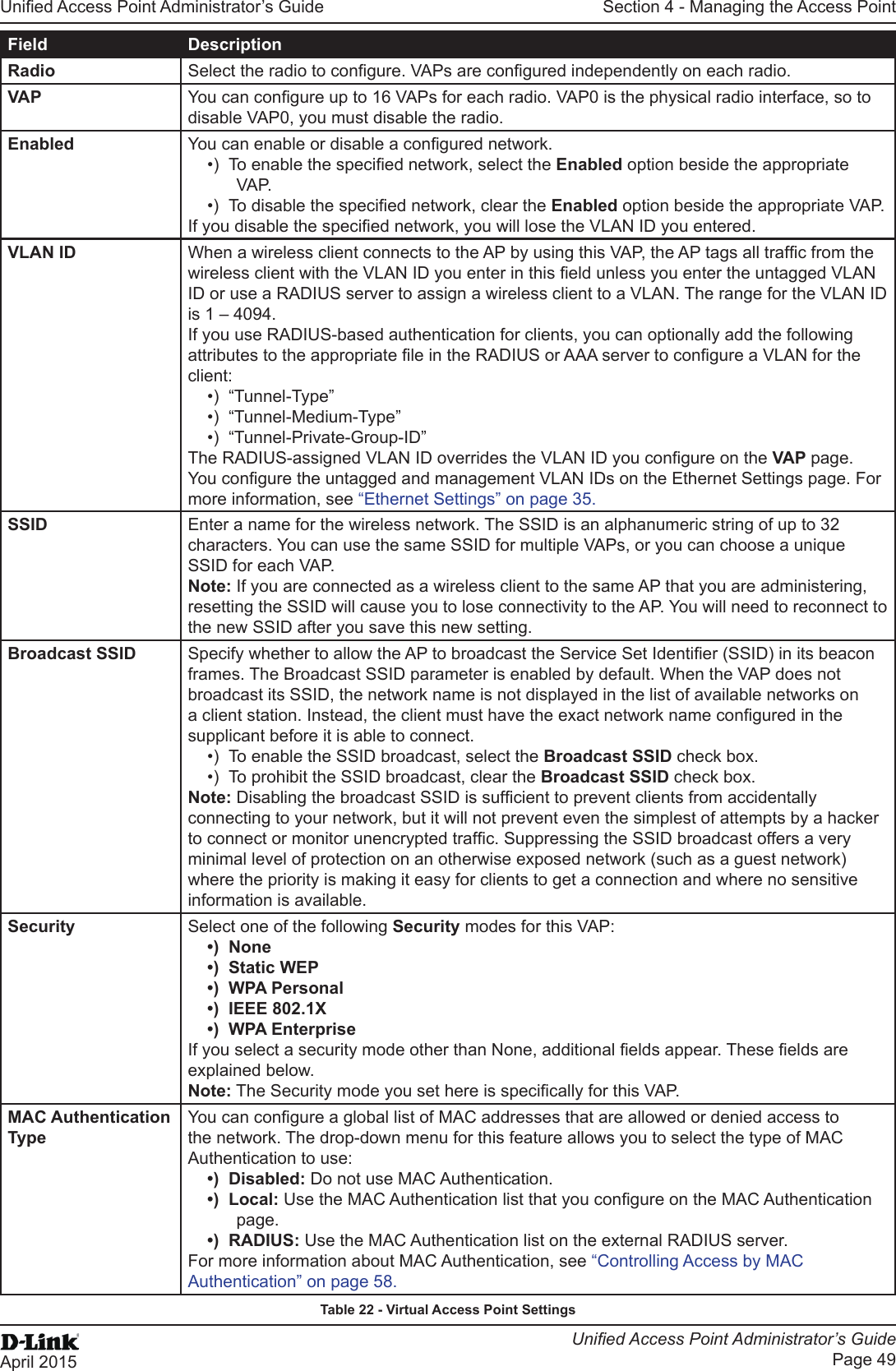
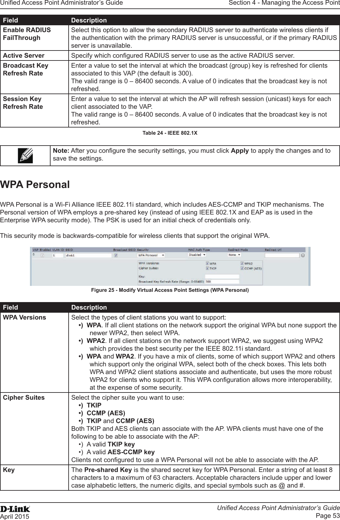
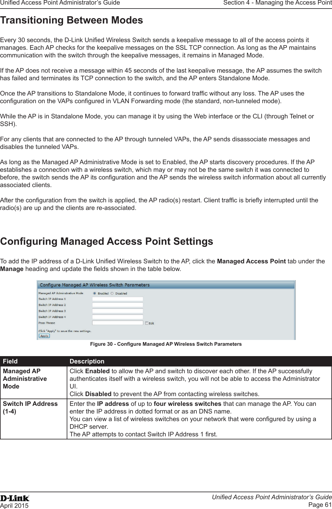
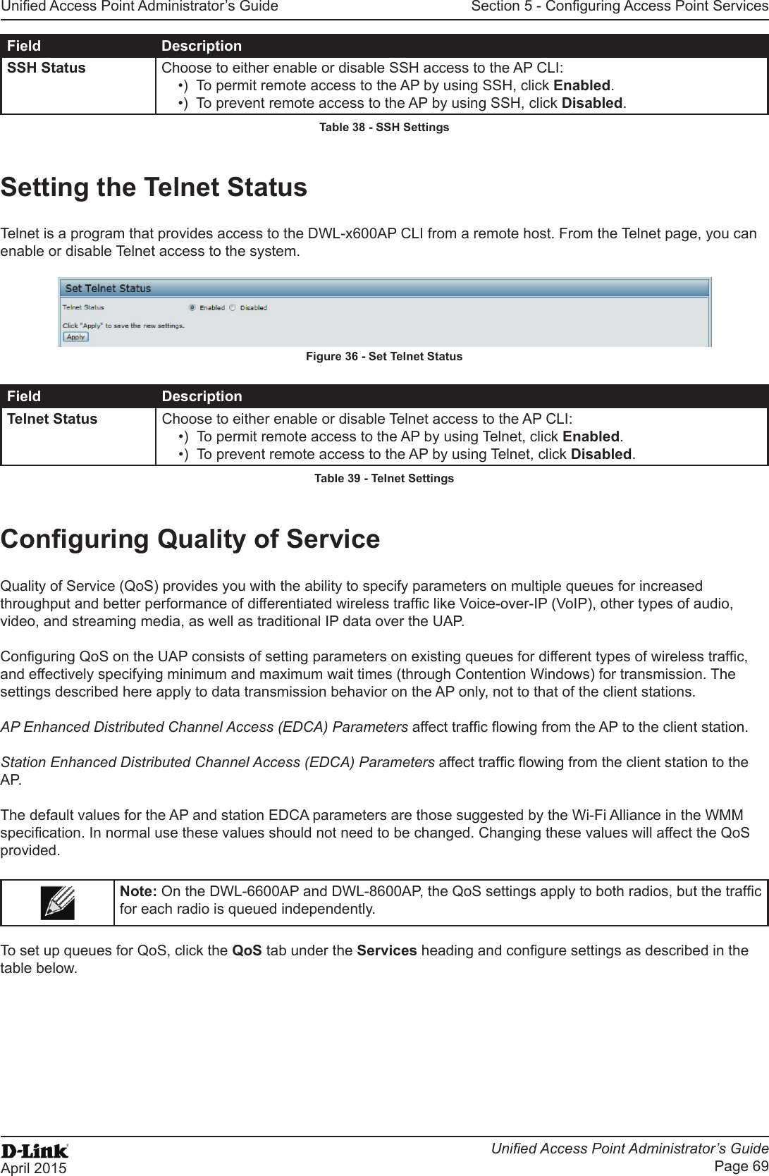
![Unied Access Point Administrator’s GuideUnied Access Point Administrator’s GuidePage 9April 2015Section 1 - About This DocumentSection 1 - About This DocumentThis guide describes setup, conguration, administration and maintenance for the D-Link DWL-x600AP Unied Access Point (UAP) on a wireless network.Document OrganizationThe Unied Access Point Administrator’s Guide contains the following sections:•) “Section 1 - About This Document” on page 9•) “Section 2 - Getting Started” on page 11•) “Section 3 - Viewing Access Point Status” on page 22•) “Section 4 - Managing the Access Point” on page 35•) “Section 5 - Conguring Access Point Services” on page 65•) “Section 6 - Conguring SNMPv3” on page 75•) “Section 7 - Maintaining the Access Point” on page 79•) “Section 8 - Conguring Client Quality of Service (QoS)” on page 88•) “Section 9 - Clustering Multiple APs” on page 104•) “Appendix A - Default AP Settings” on page 113•) “Appendix B - Conguration Examples” on page 115Additional DocumentationThe following documentation provides additional information about Unied Access Point software:•) The Unied Access Point CLI Command Reference describes the commands available from the command-line interface (CLI) for managing, monitoring, and conguring the switch.•) The User Manual for the D-Link Unied Wired and Wireless System provides information about setting up and managing the Unied Wireless Switch (UWS), including information about how to use the switch to manage multiple UAPs. •) Release notes for the D-Link Unied Wired and Wireless System detail the platform-specic functionality of the software packages, including issues and workarounds.Document ConventionsThis section describes the conventions this document uses.Note: A note provides more information about a feature or technology and cross-references to related topics.Caution! A caution provides information about critical aspects of AP conguration, combinations of settings, events, or procedures that can adversely affect network connectivity, security, and so on.The following table describes the typographical conventions used in this guide.Symbol Example DescriptionBold Click Apply to save your settings. Menu titles, page names, and button names.Blue Text See “Document Conventions” on page 9Hyperlink text.Courier Font WLAN-AP# show network Screen text, le names, commands, user-typed command-line entries.Courier Font ItalicsValue Command parameter, which might be a variable or xed value.Square Brackets [ ] [Value] Indicates an optional xed parameter.](https://usermanual.wiki/D-Link/WL6700APA1/User-Guide-2662295-Page-9.png)
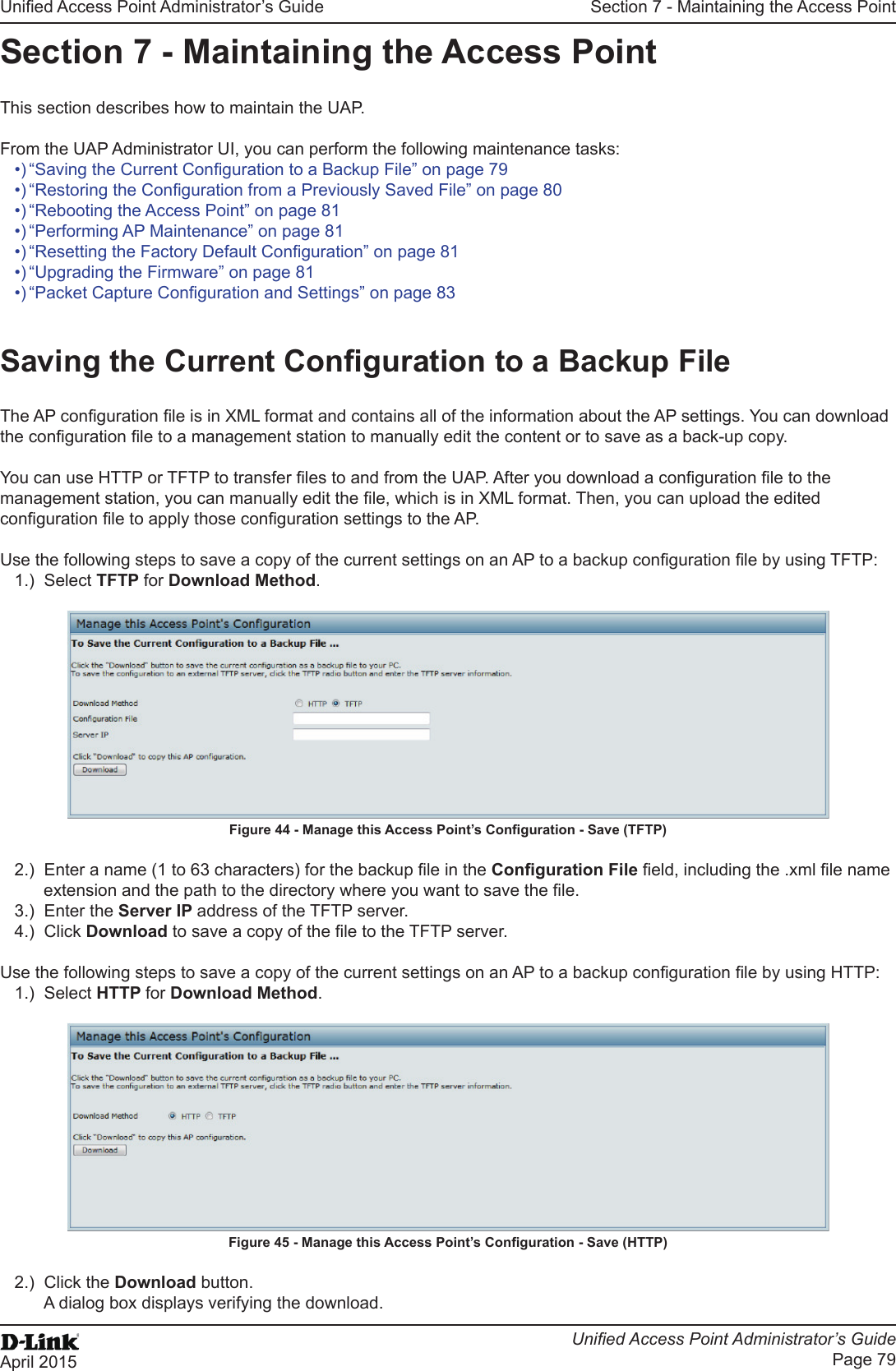
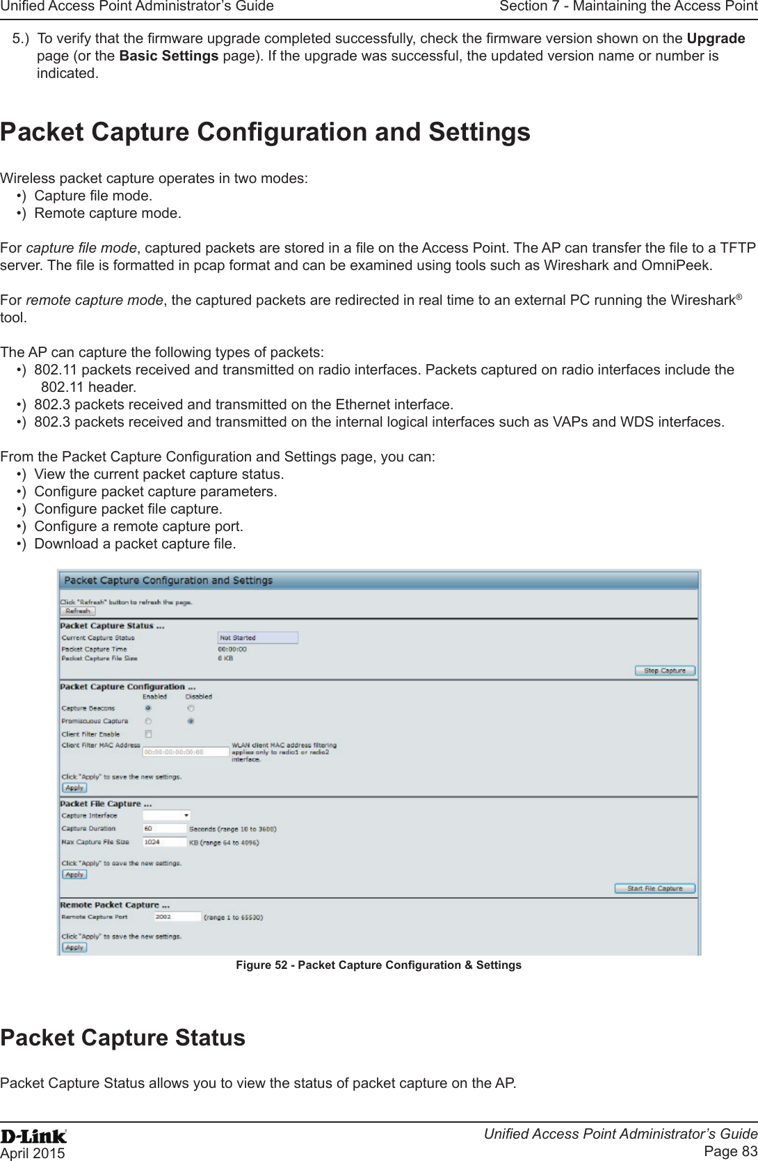
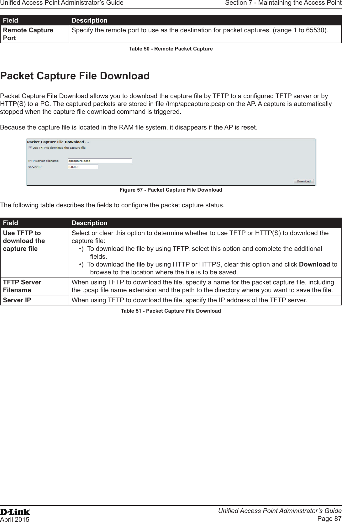
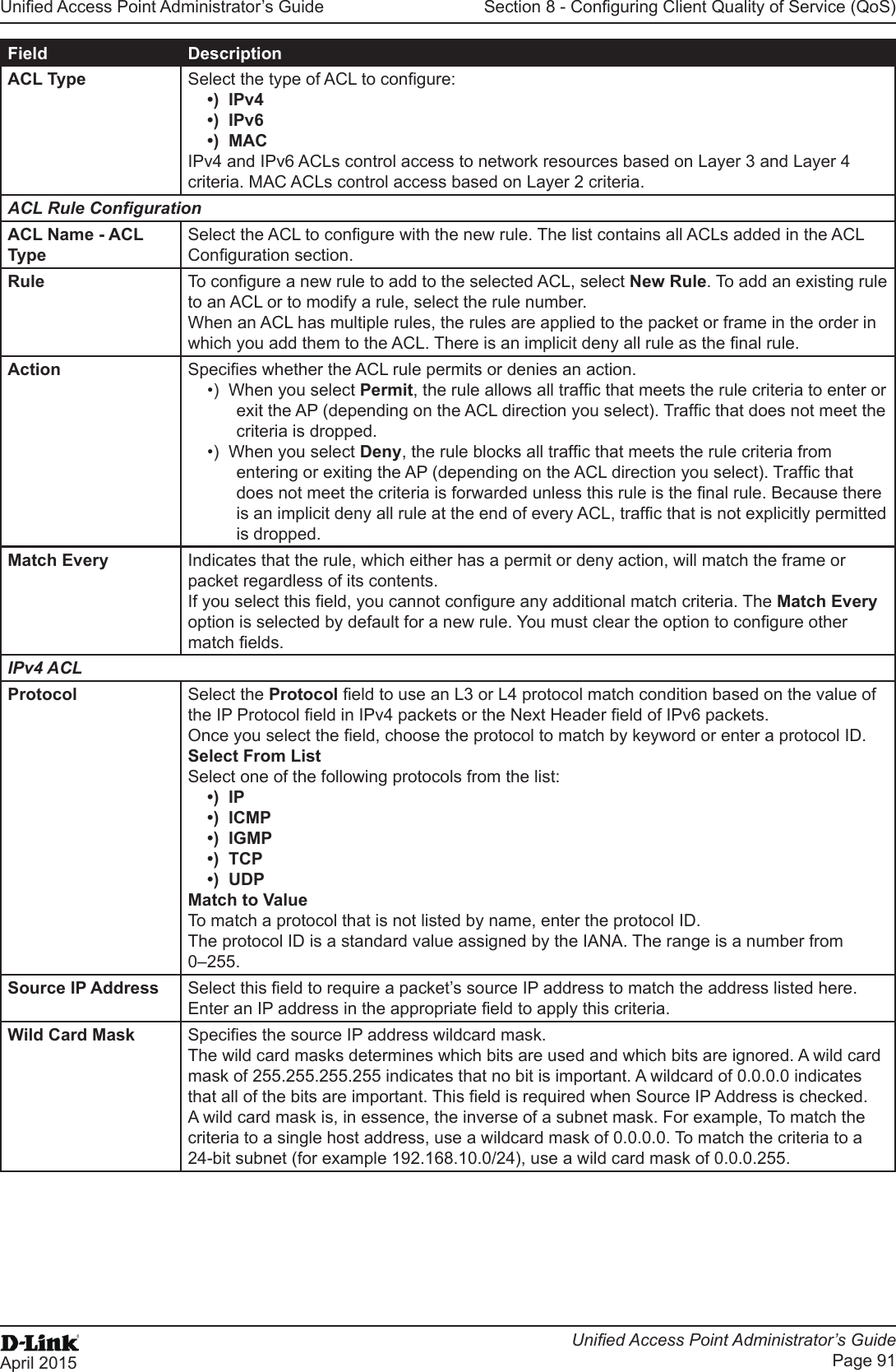
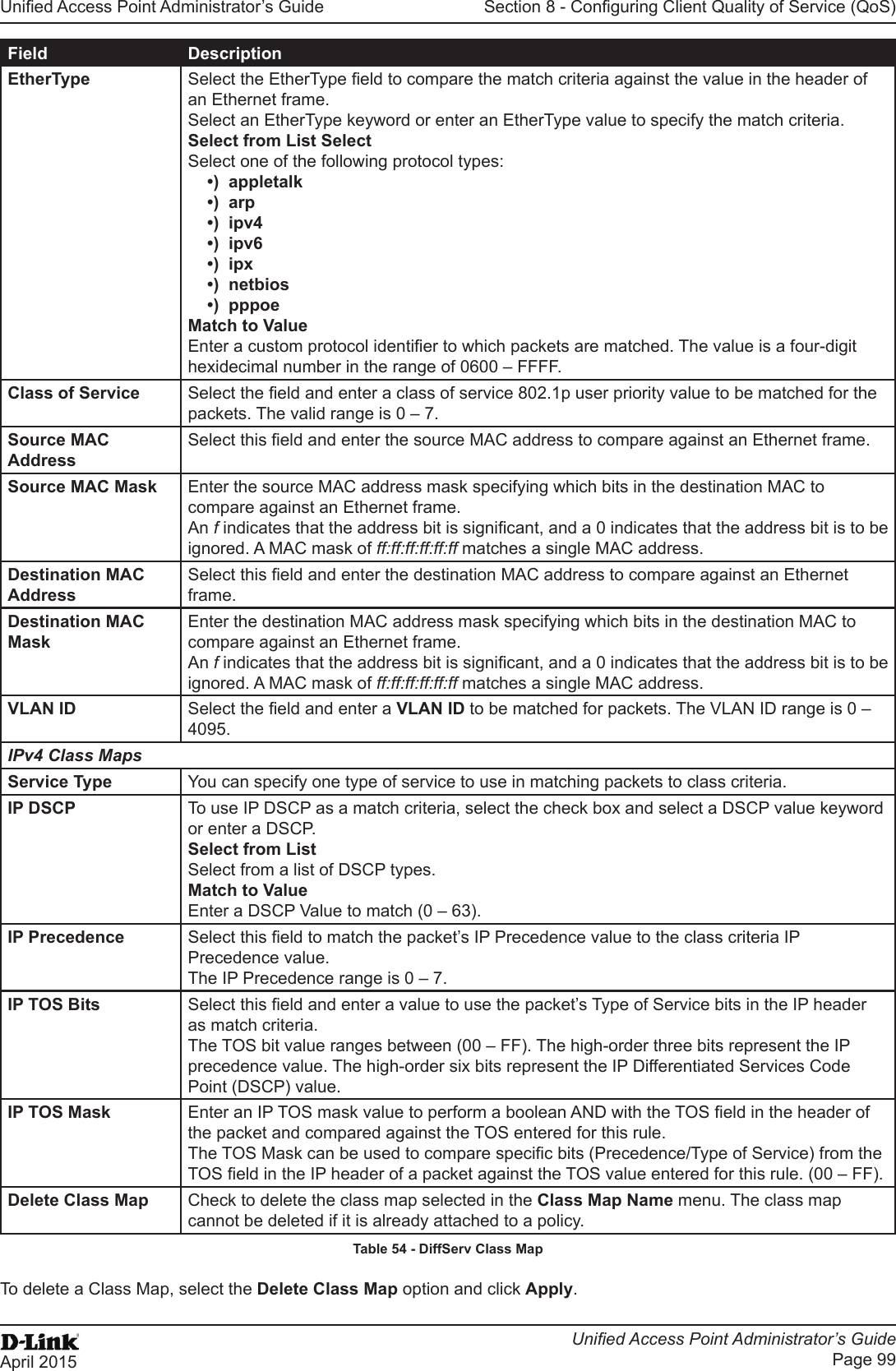
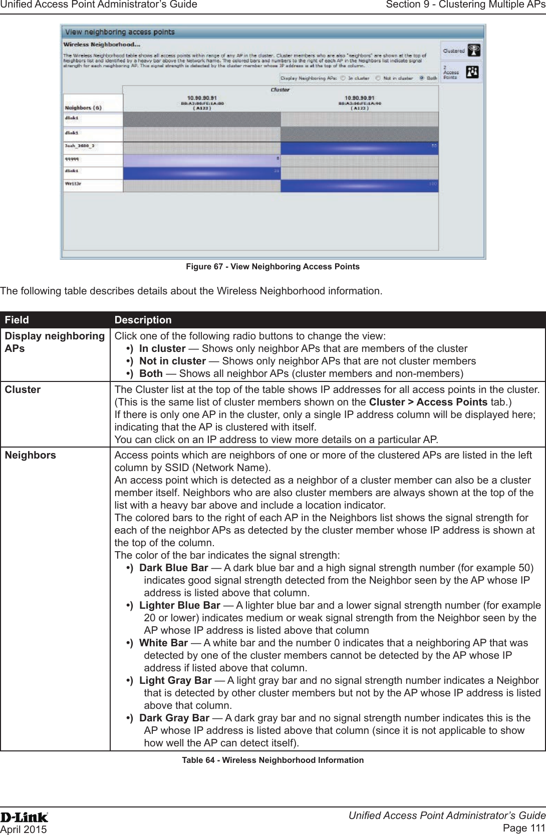
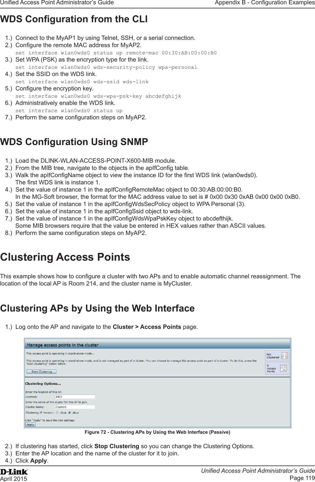
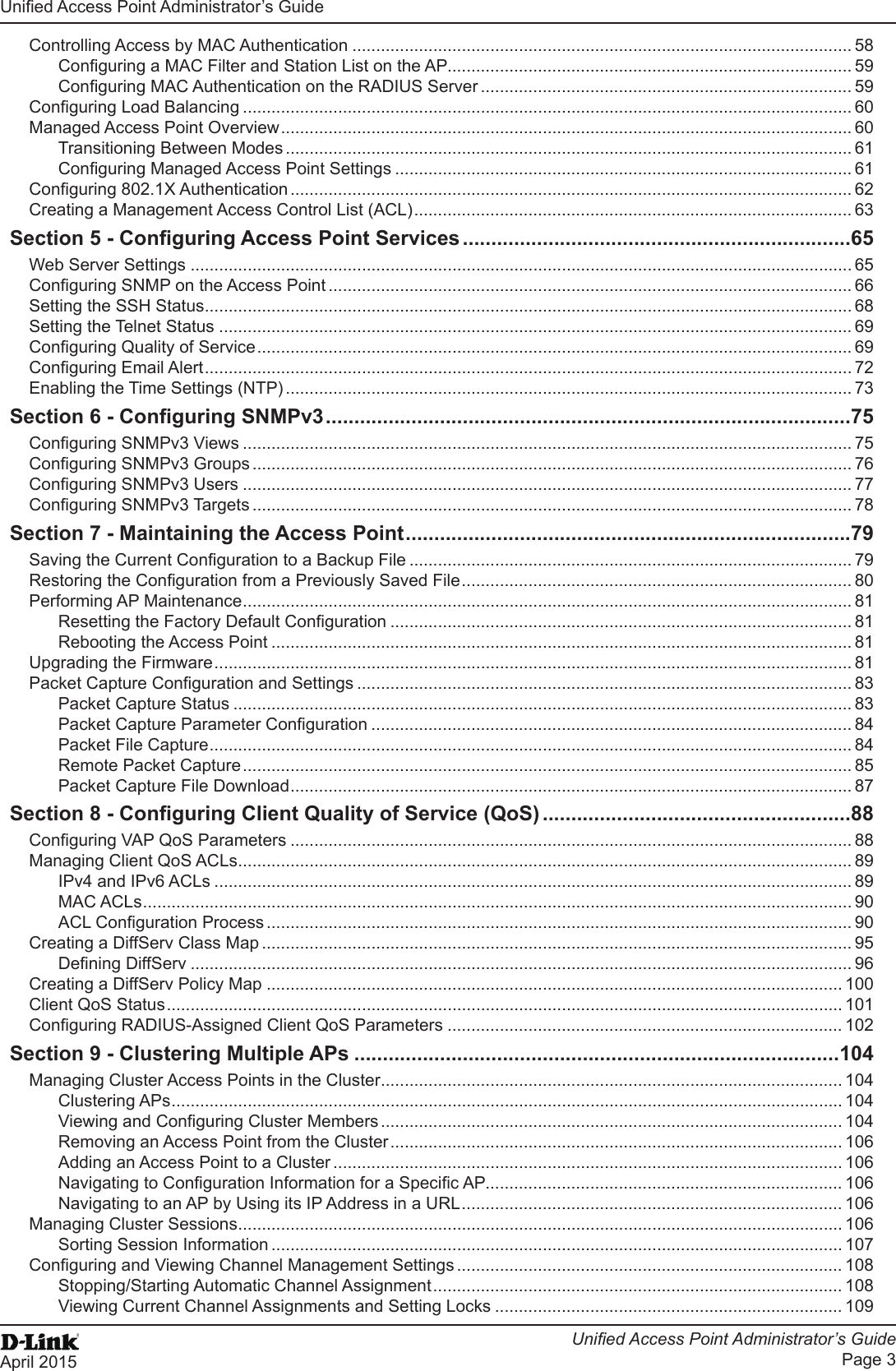
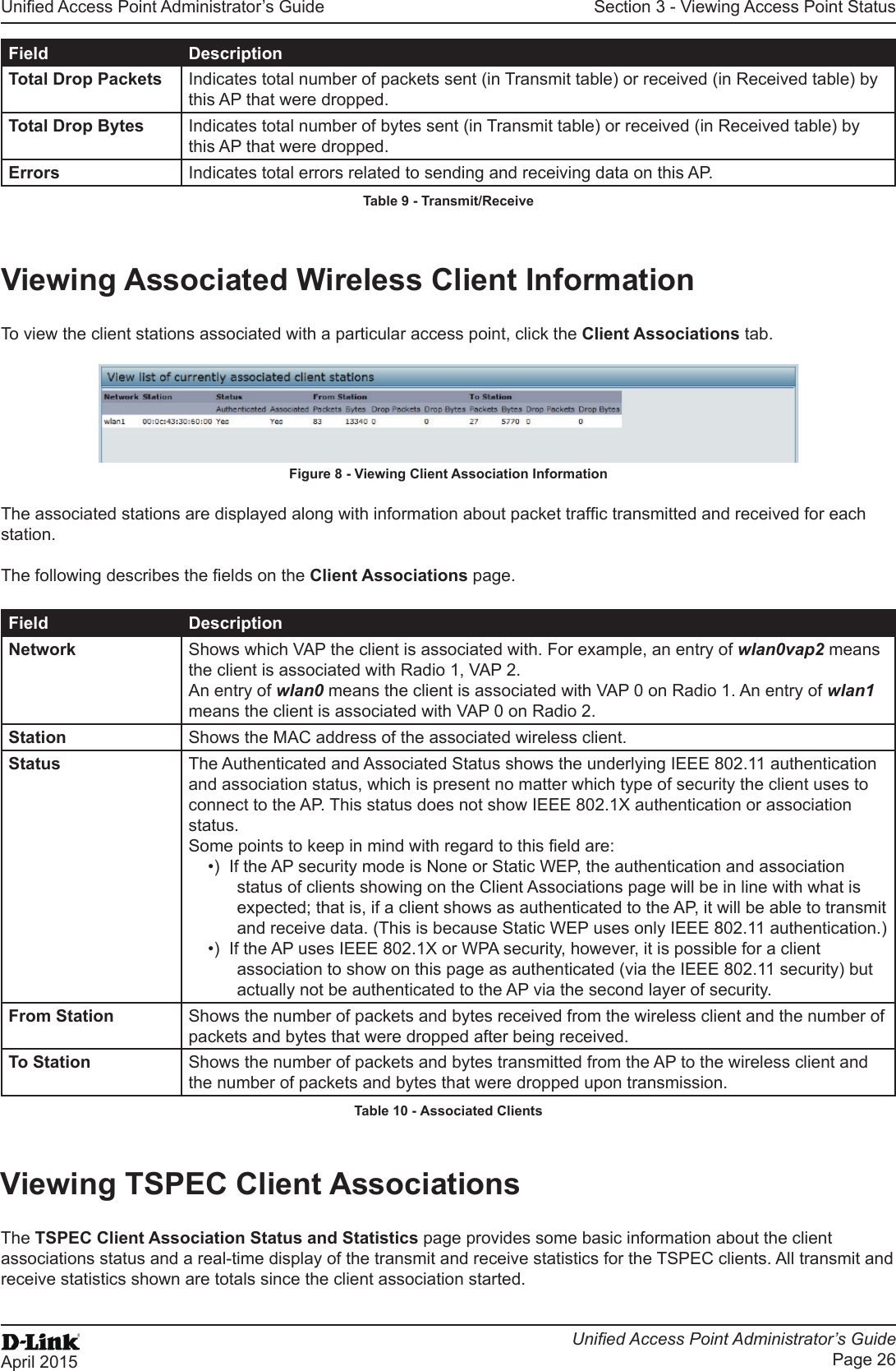
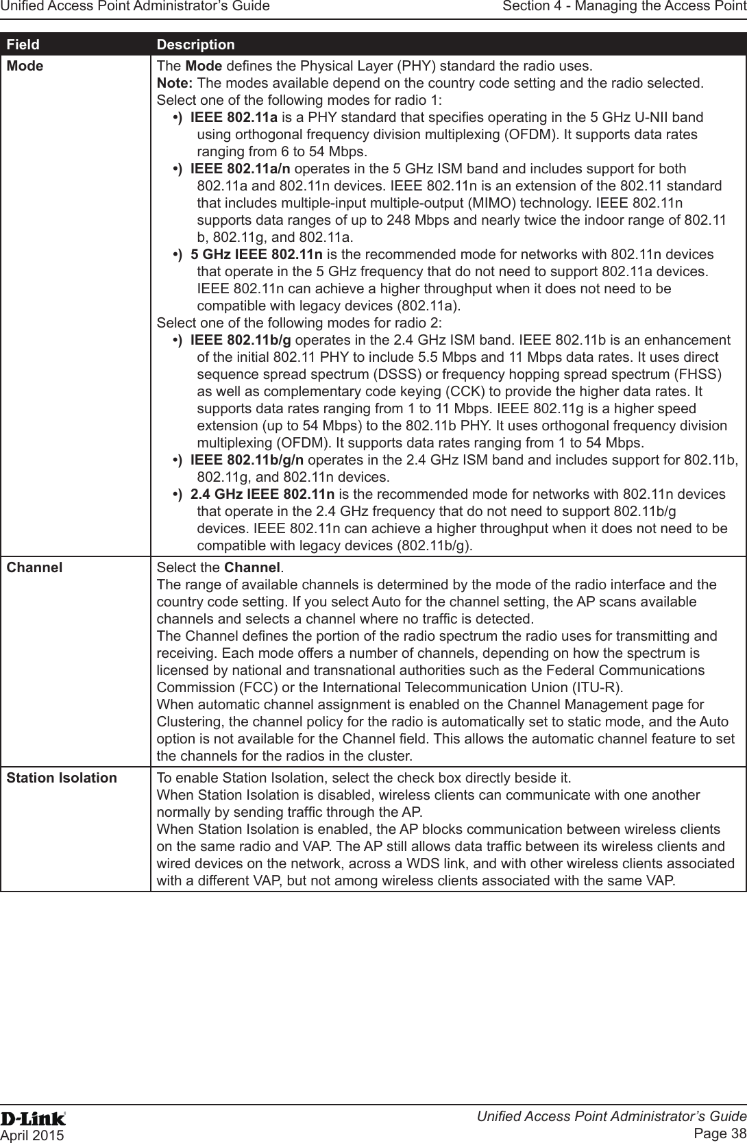
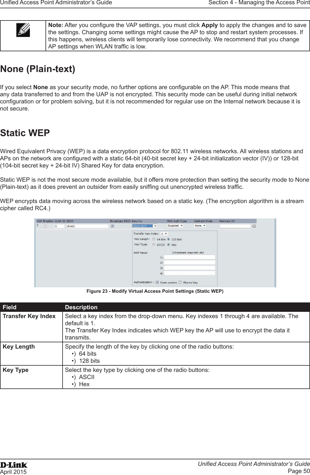
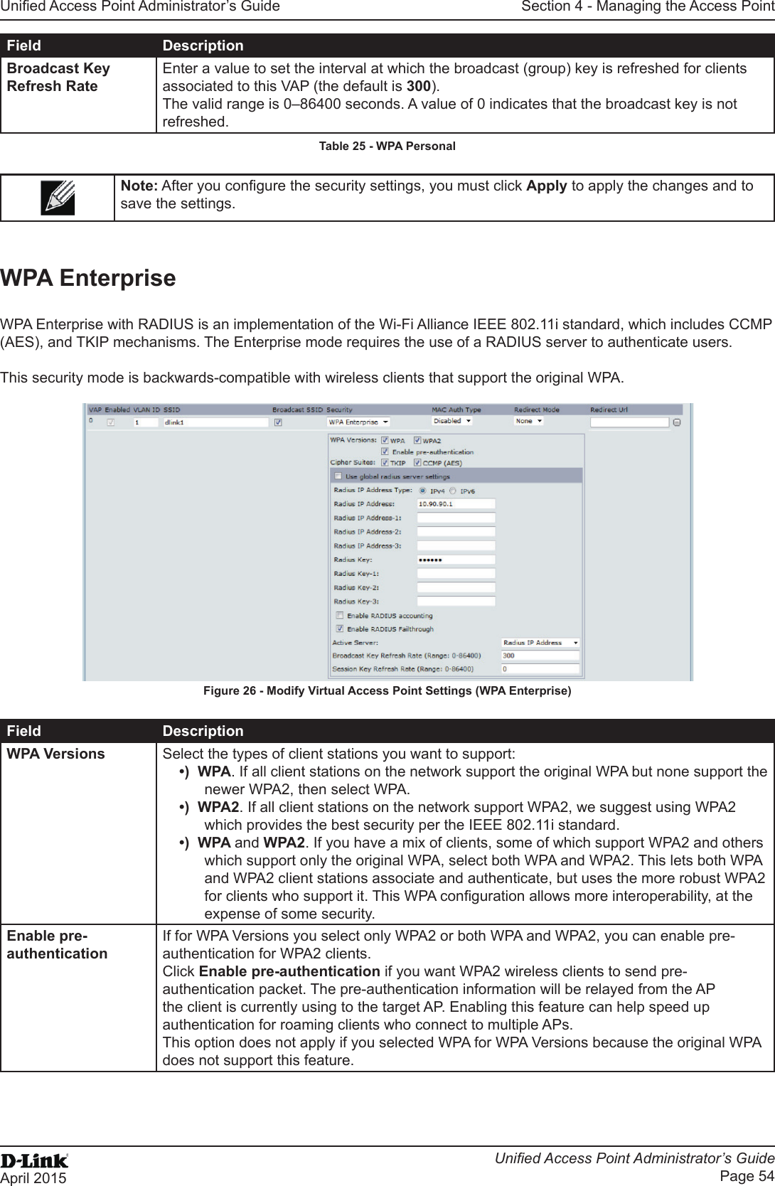
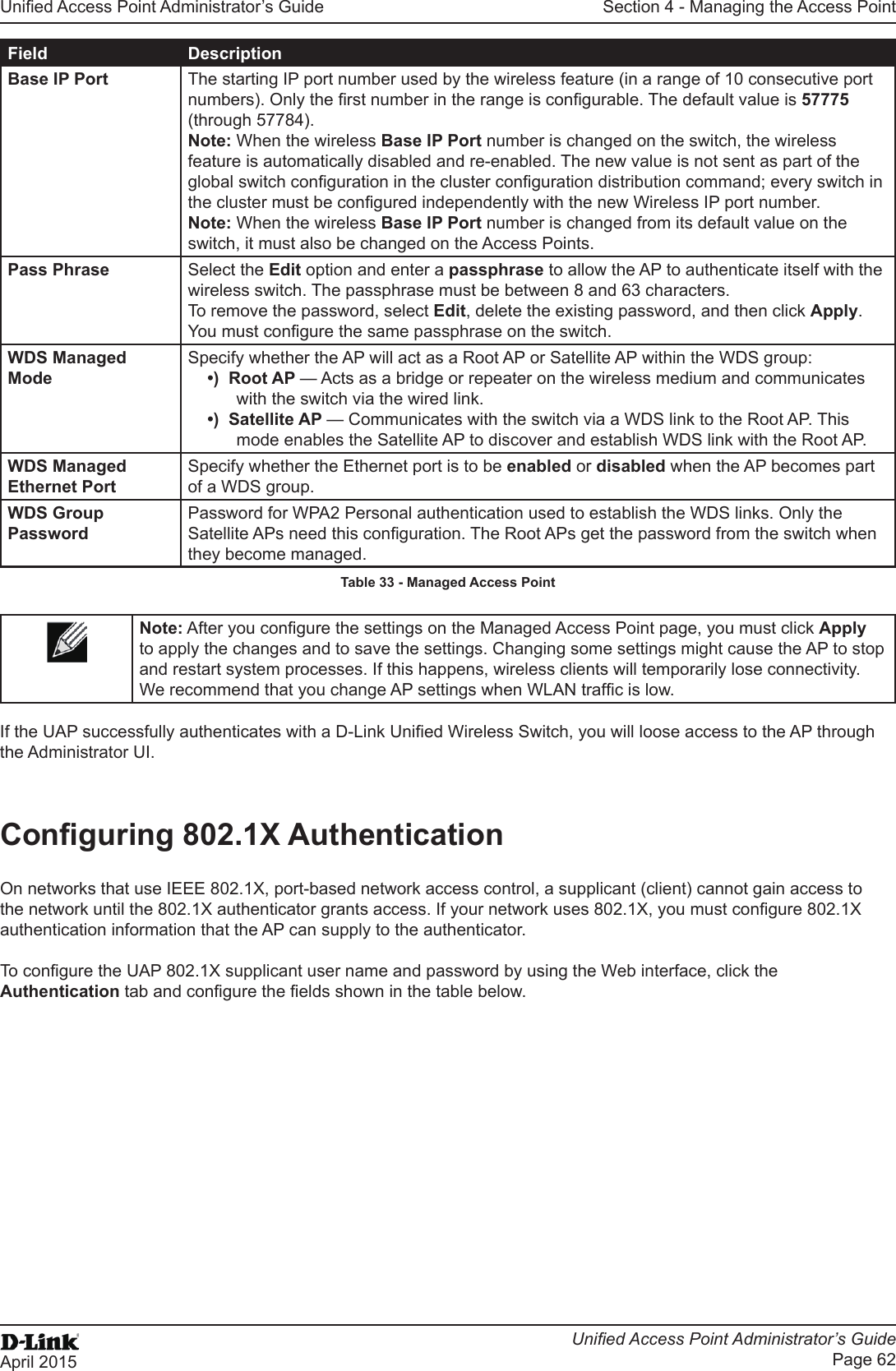
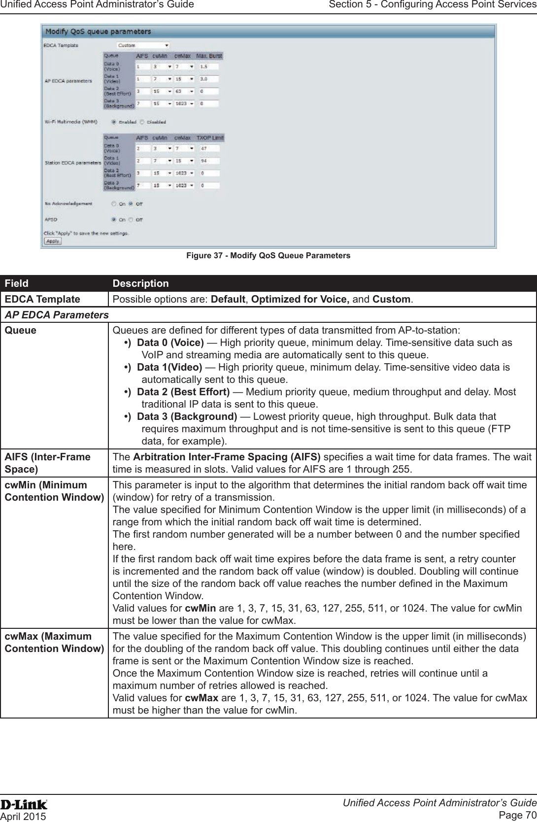
![Unied Access Point Administrator’s GuideUnied Access Point Administrator’s GuidePage 10April 2015Section 1 - About This DocumentSymbol Example DescriptionCurly Braces {} {Choice1 | Choice2} Indicates that you must select a parameter from the list of choices.Vertical Bars | Choice1 | Choice2 Separates the mutually exclusive choices.Braces within square brackets [{}][{Choice1 | Choice2}] Indicate a choice within an optional element.Table 1 - Typographical ConventionsOnline Help, Supported Browsers, and LimitationsOnline help for the UAP Administration Web pages provides information about all elds and features available from the user interface (UI). The information in the online help is a subset of the information available in the Unied Access Point Administrator’s Guide.Online help information corresponds to each page on the UAP Administration UI. For information about the settings on the current page, click the Help link on the upper right side of a page. The following gure shows an example of the online help available from the links on the user interface.Figure 1 - Administrator UI Online Help](https://usermanual.wiki/D-Link/WL6700APA1/User-Guide-2662295-Page-10.png)
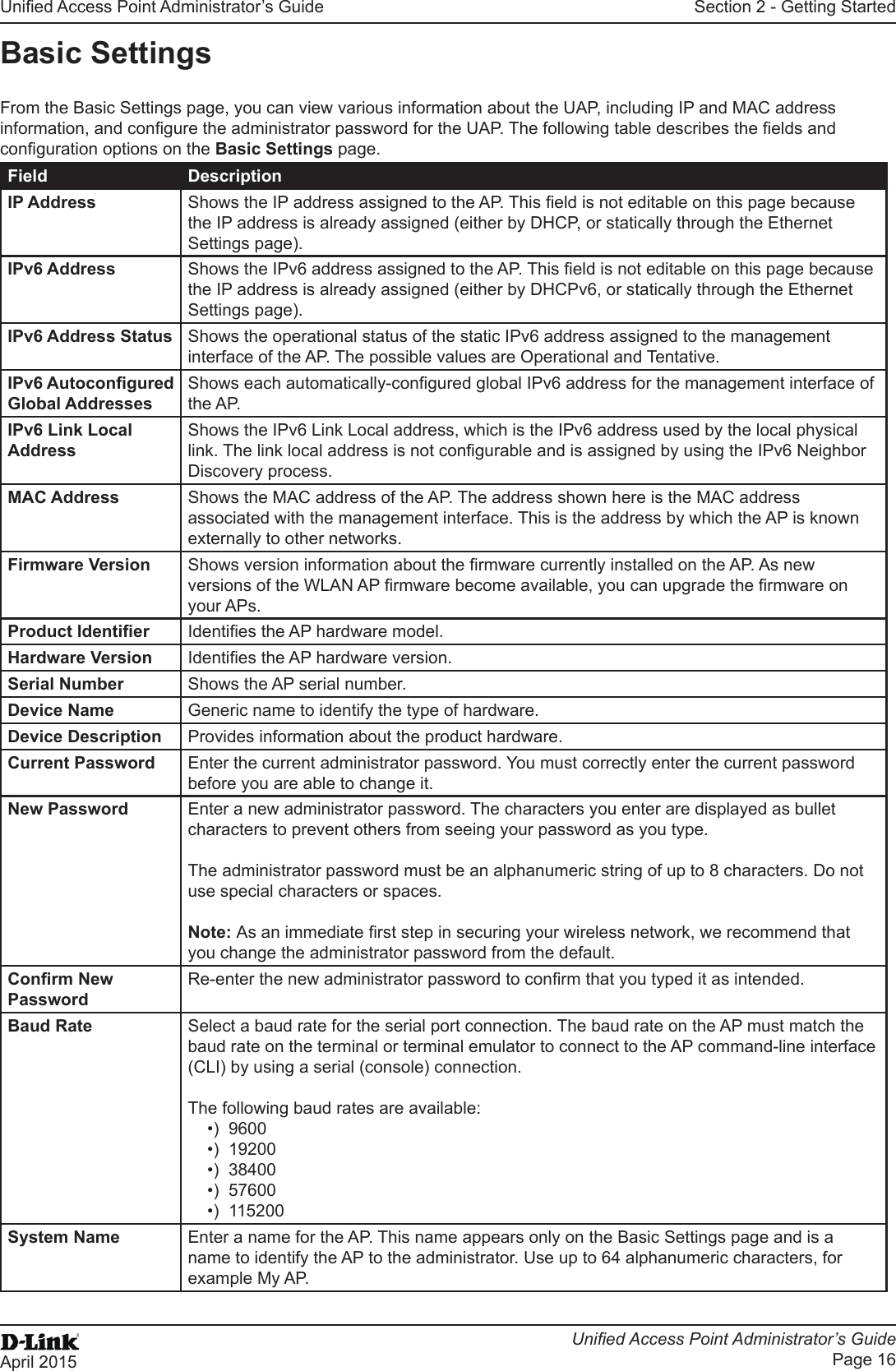
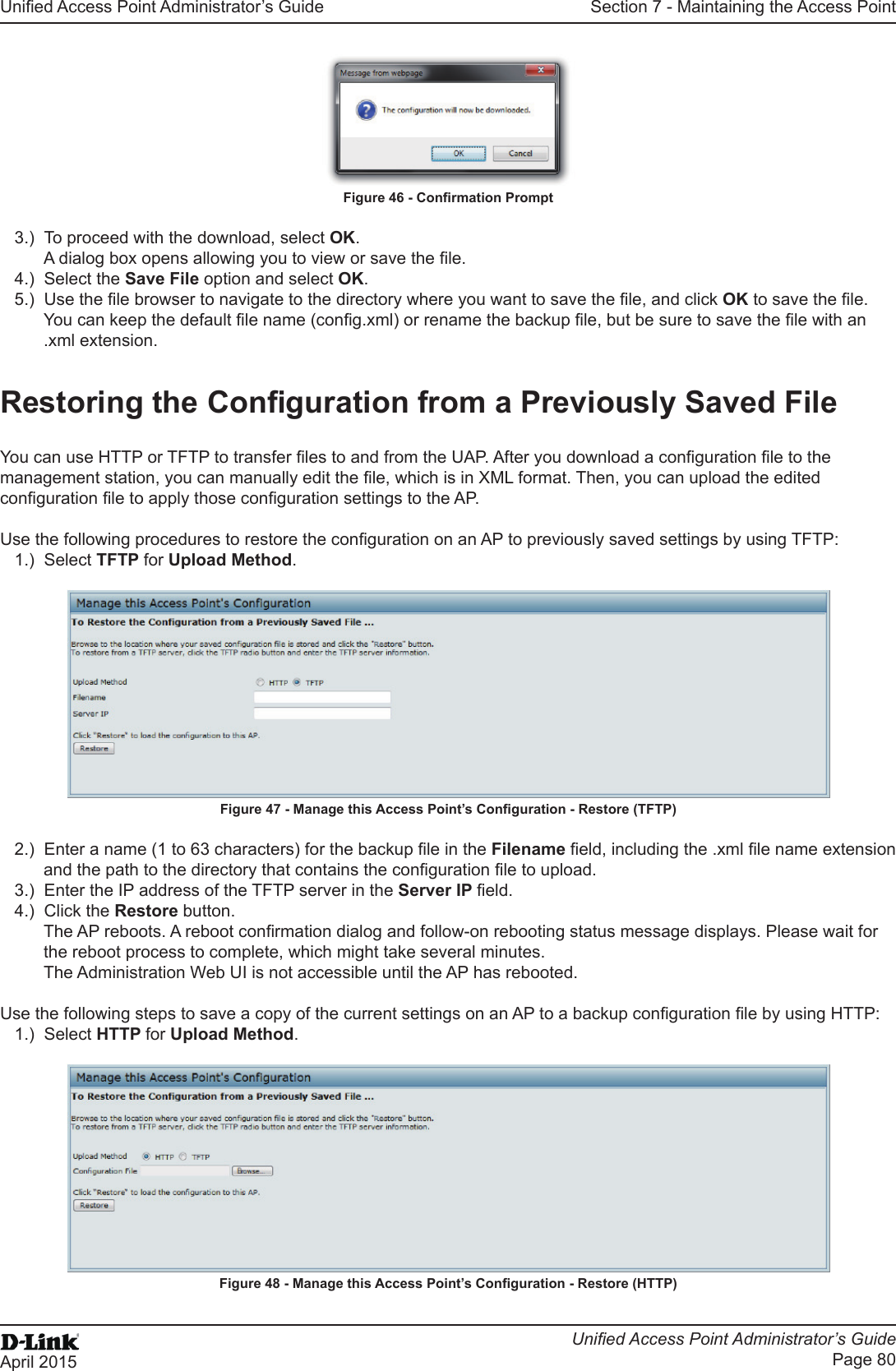
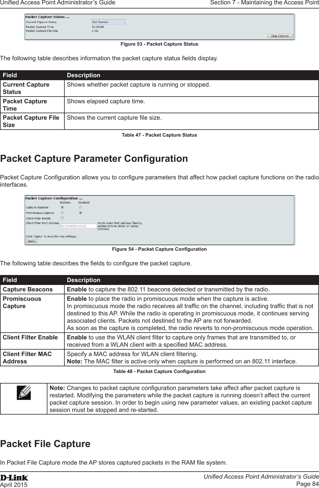
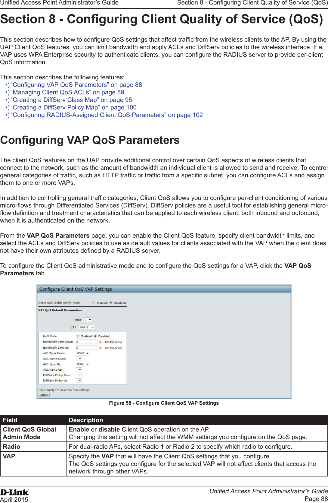
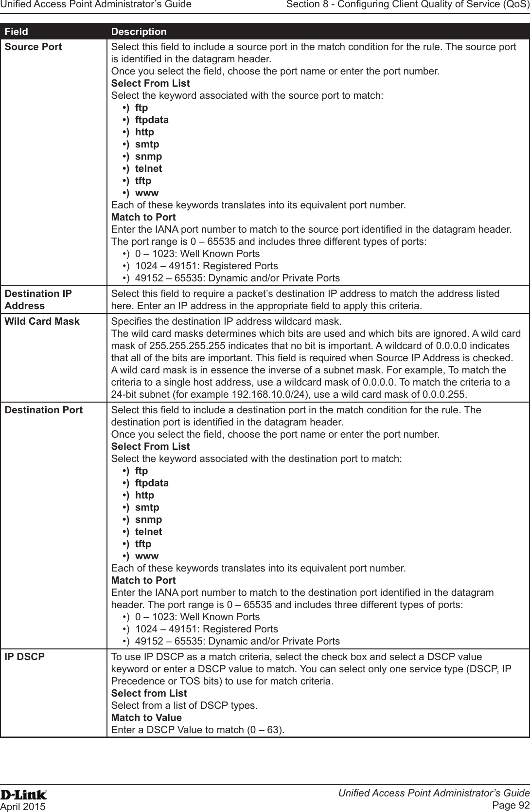
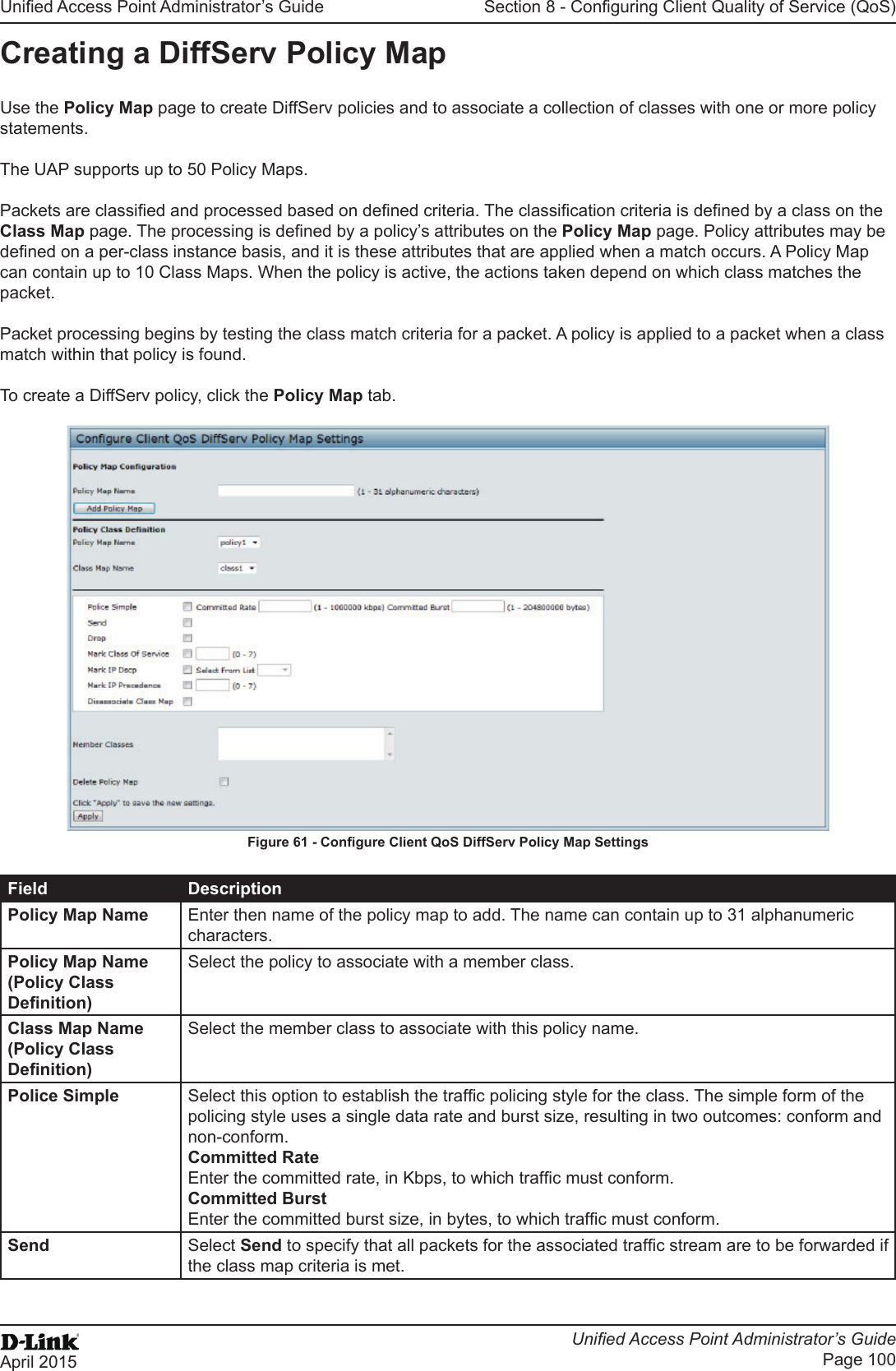
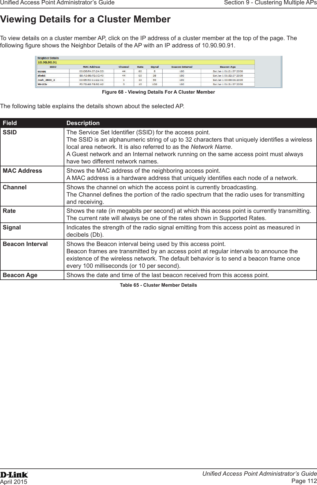
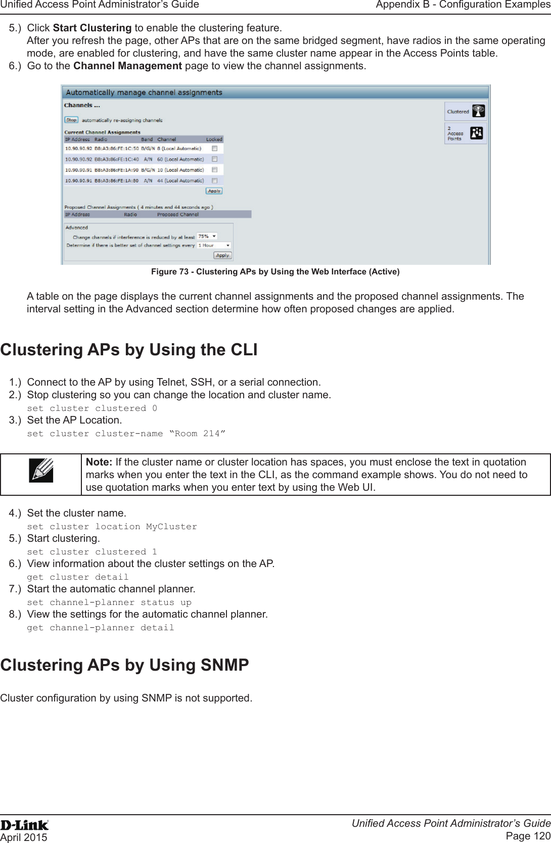
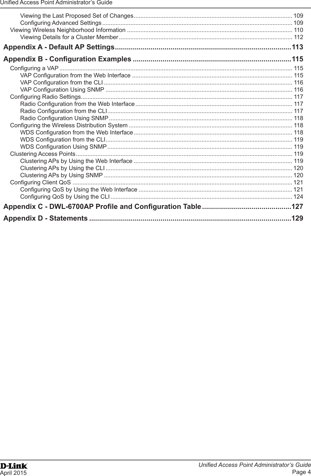
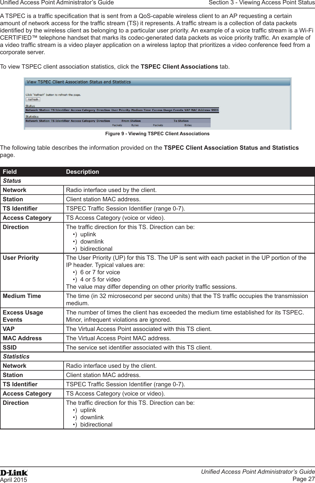
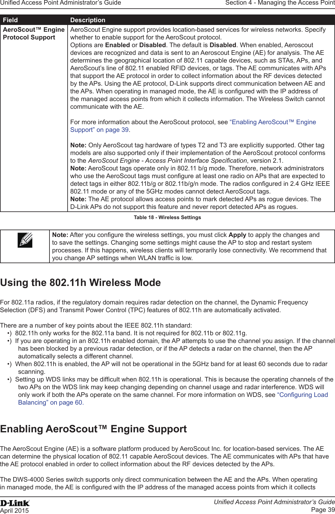
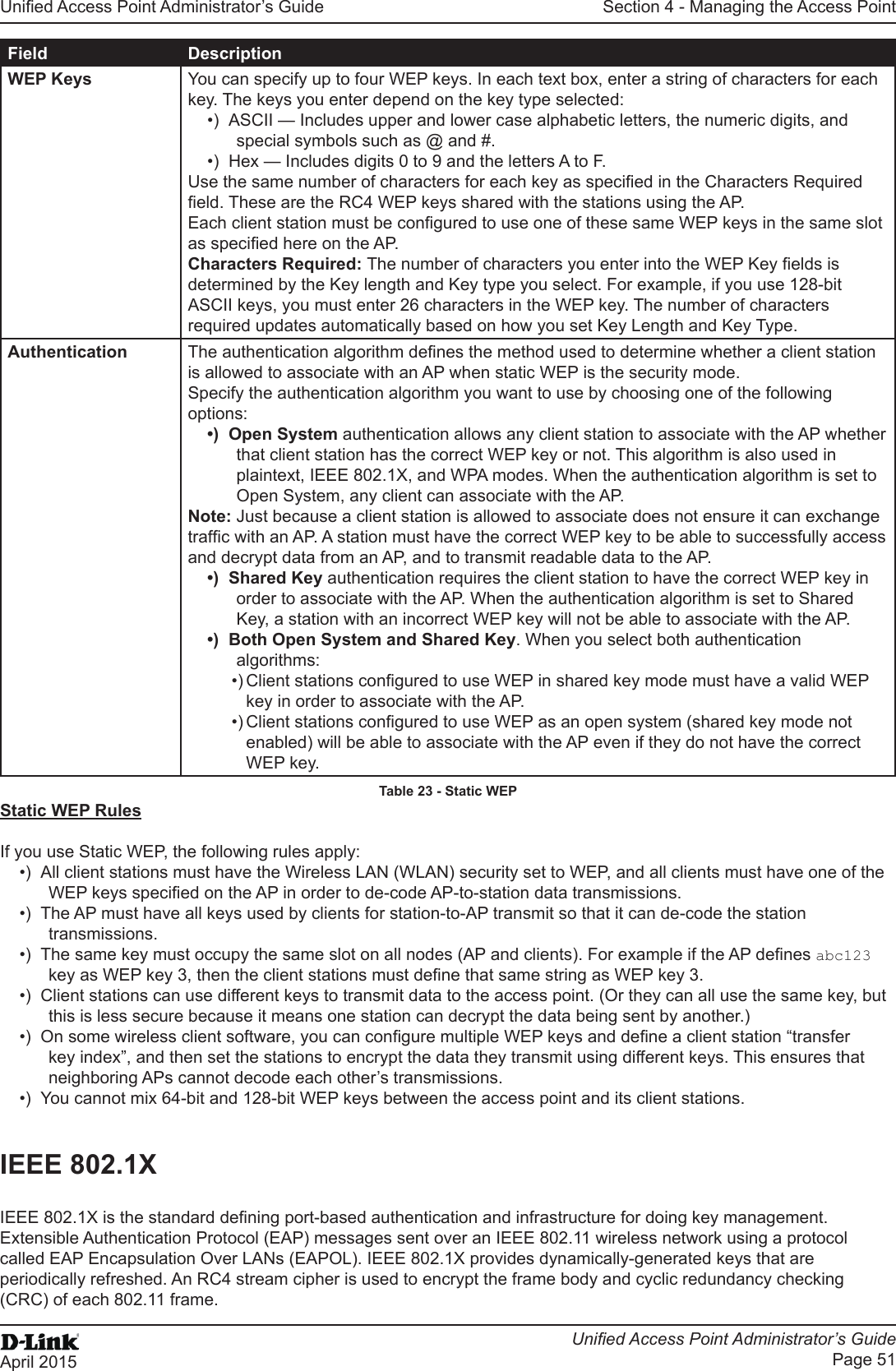
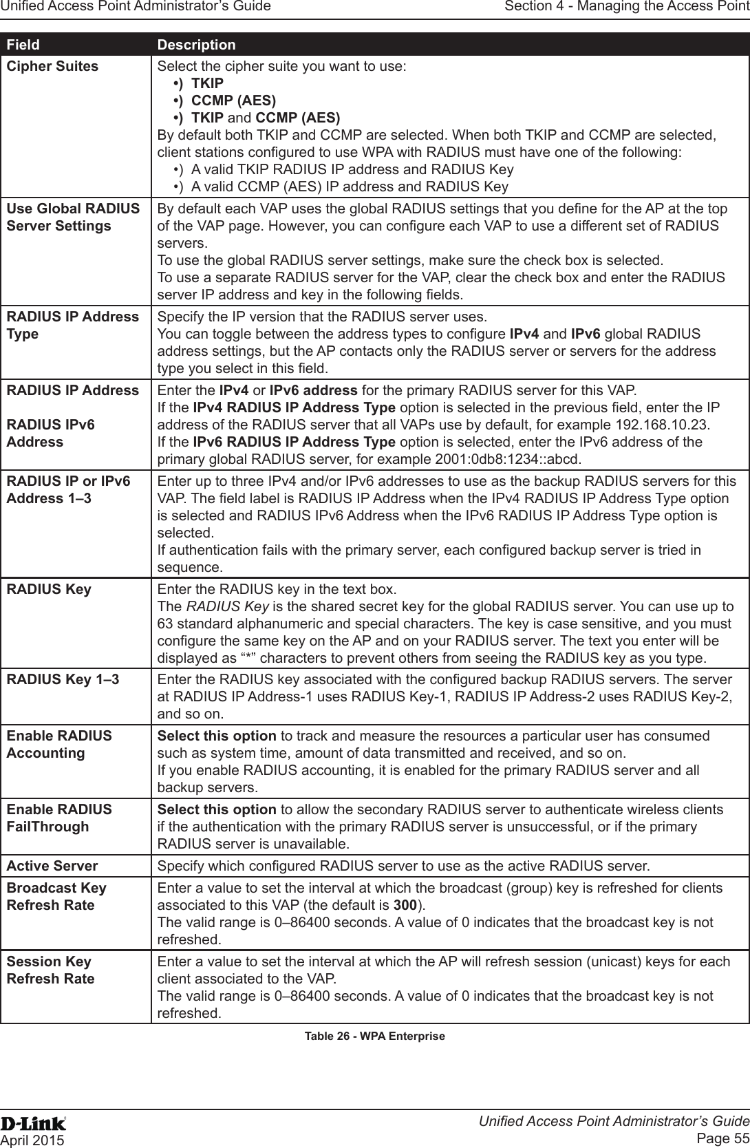
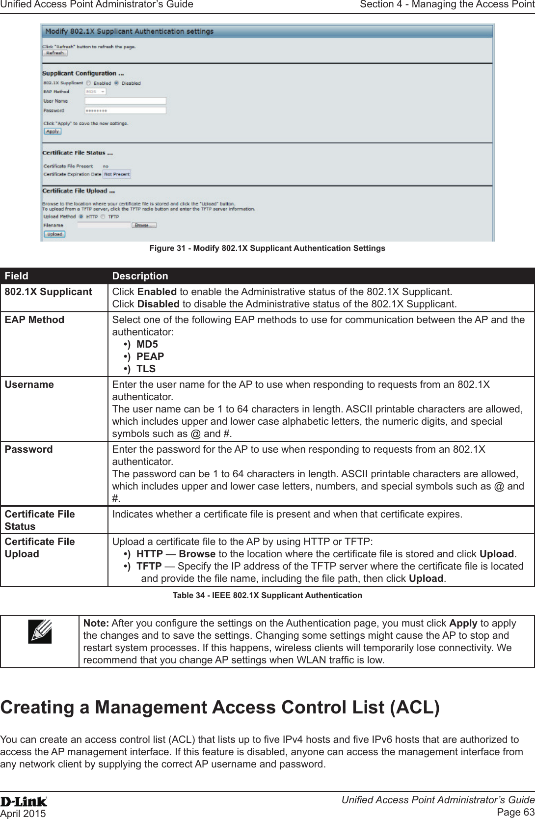
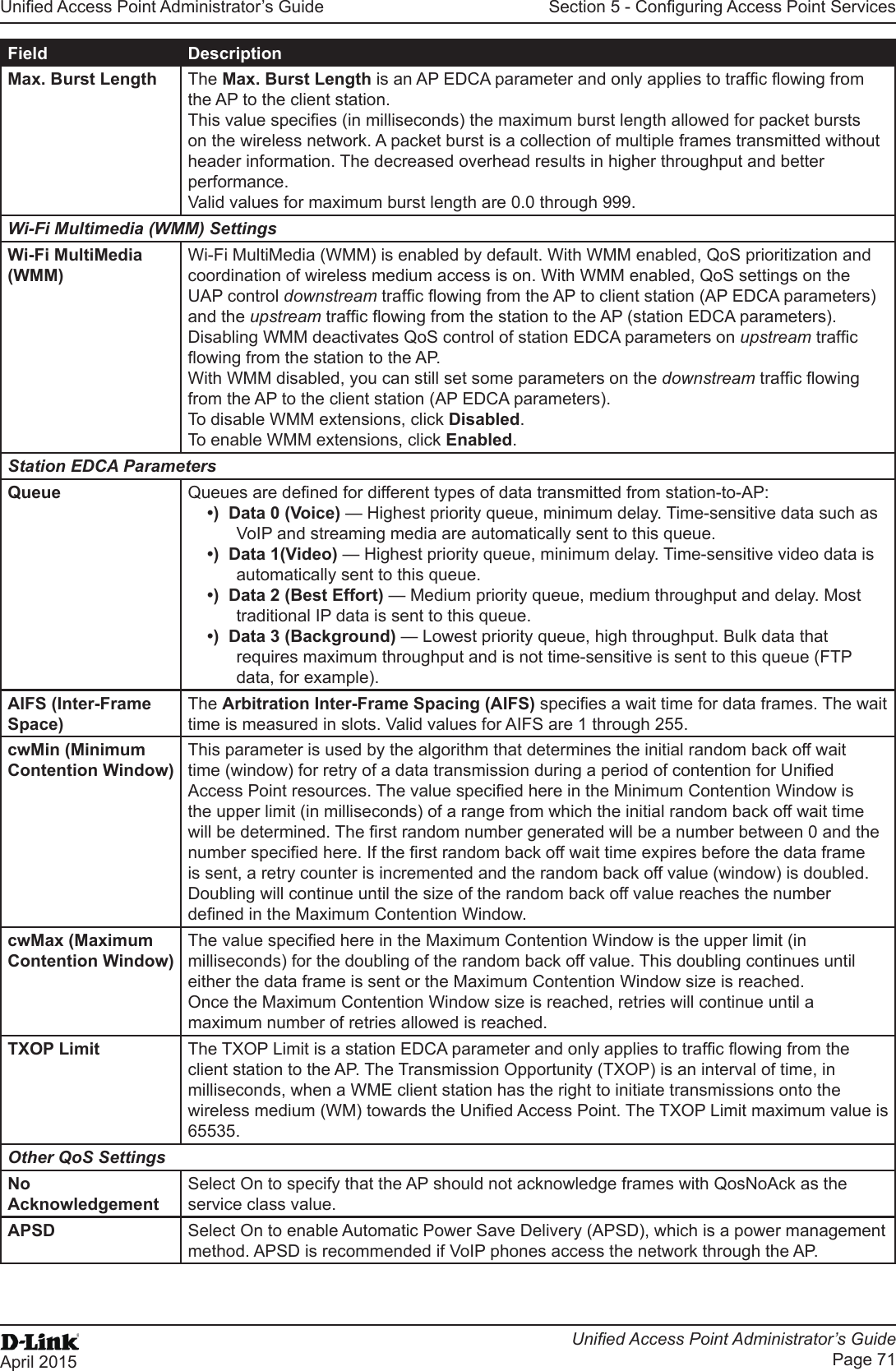
![Unied Access Point Administrator’s GuideUnied Access Point Administrator’s GuidePage 17April 2015Section 2 - Getting StartedField DescriptionSystem Contact Enter the name, e-mail address, or phone number of the person to contact regarding issues related to the AP.System Location Enter the physical location of the AP, for example Conference Room A.Table 4 - Basic Settings PageConnecting to the AP Web Interface by Using the IPv6 AddressTo connect to the AP by using the IPv6 global address or IPv6 link local address, you must enter the AP address into your browser in a special format.Note: The following instructions and examples work with Microsoft Internet Explorer 7 (IE7) and might not work with other browsers.To connect to an IPv6 global address, add square brackets around the IPv6 address. For example, if the AP global IPv6 address is 2520::230:abff:fe00:2420, type the following address into the IE7 address eld: http://[2520::230:abff:fe00:2420].To connect to the iPv6 link local address, replace the colons (:) with hyphens (-), add the interface number preceded with an “s,” then add “.ipv6-literal.net.” For example, if the AP link local address is fe80::230:abff:fe00:2420, and the Windows interface is dened as “%6,” type the following address into the IE7 address eld: http://fe80--230-abff-fe00-2420s6.ipv6-literal.net.Using the CLI to View the IP AddressThe DHCP client on the UAP is enabled by default. If you connect the UAP to a network with a DHCP server, the AP automatically acquires an IP address. To manage the UAP by using the Administrator UI, you must enter the IP address of the access point into a Web browser. If a DHCP server on your network assigns an IP address to the UAP, and you do not know the IP address, use the following steps to view the IP address of the UAP:1.) Using a null-modem cable, connect a VT100/ANSI terminal or a workstation to the console (serial) port.If you attached a PC, Apple, or UNIX workstation, start a terminal-emulation program, such as HyperTerminal or TeraTerm.2.) Congure the terminal-emulation program to use the following settings:•) Baud rate: 115200 bps•) Data bits: 8•) Parity: none•) Stop bit: 1•) Flow control: none3.) Press the return key, and a login prompt should appear.The login name is admin. The default password is admin. After a successful login, the screen shows the (Access Point Name)# prompt. 4.) At the login prompt, enter get management.Information similar to the following prints to the screen.](https://usermanual.wiki/D-Link/WL6700APA1/User-Guide-2662295-Page-17.png)
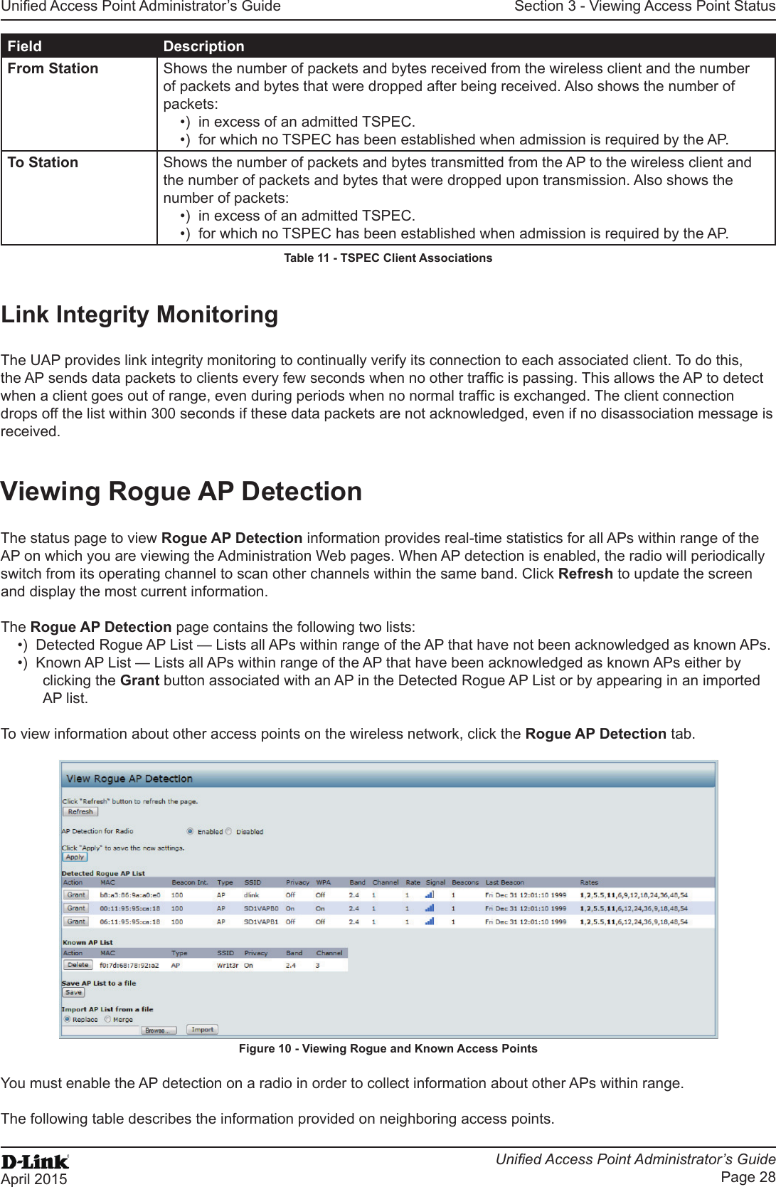
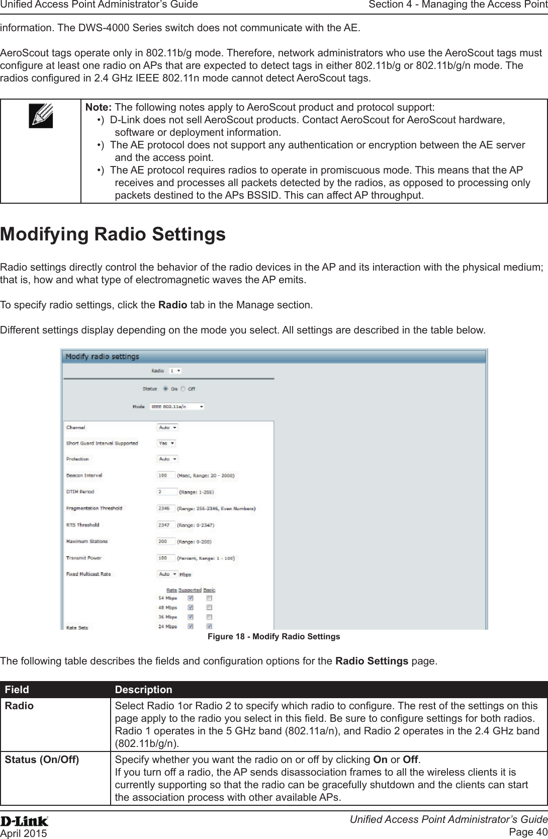
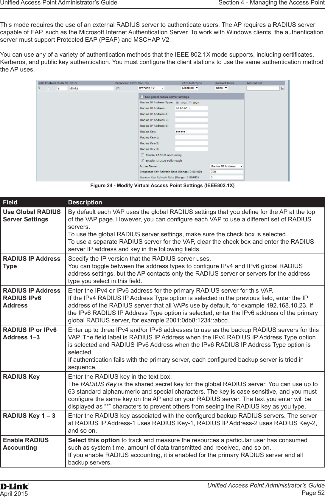
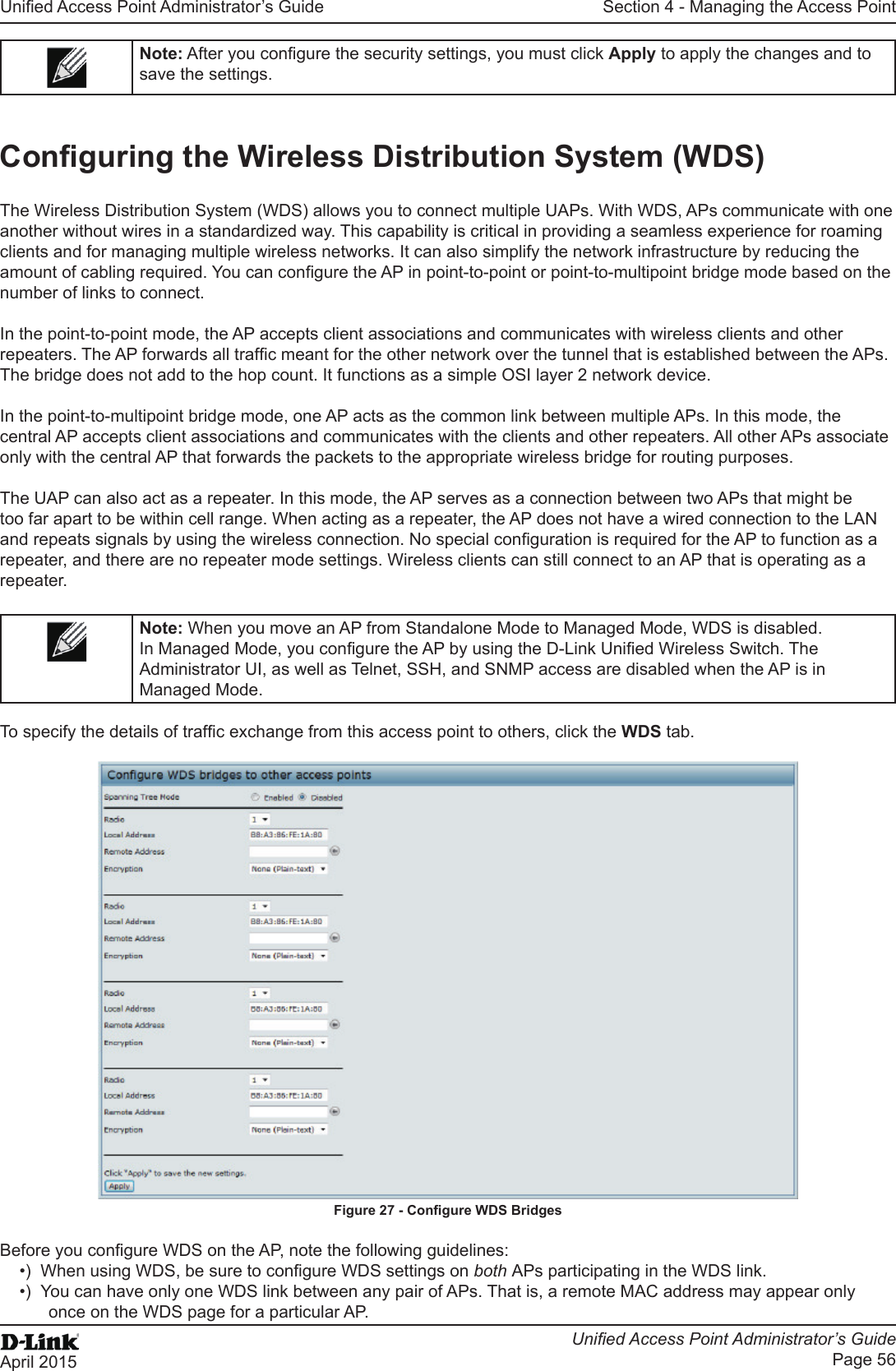
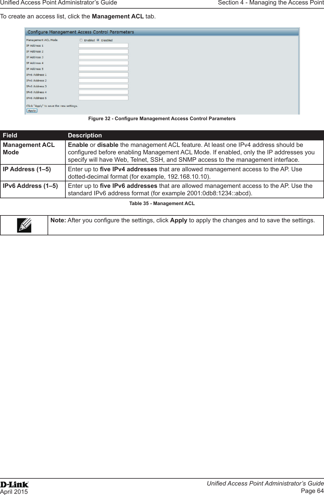
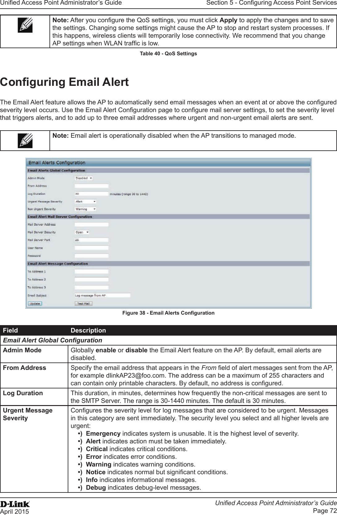
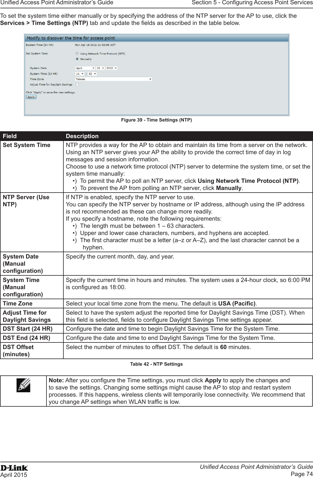
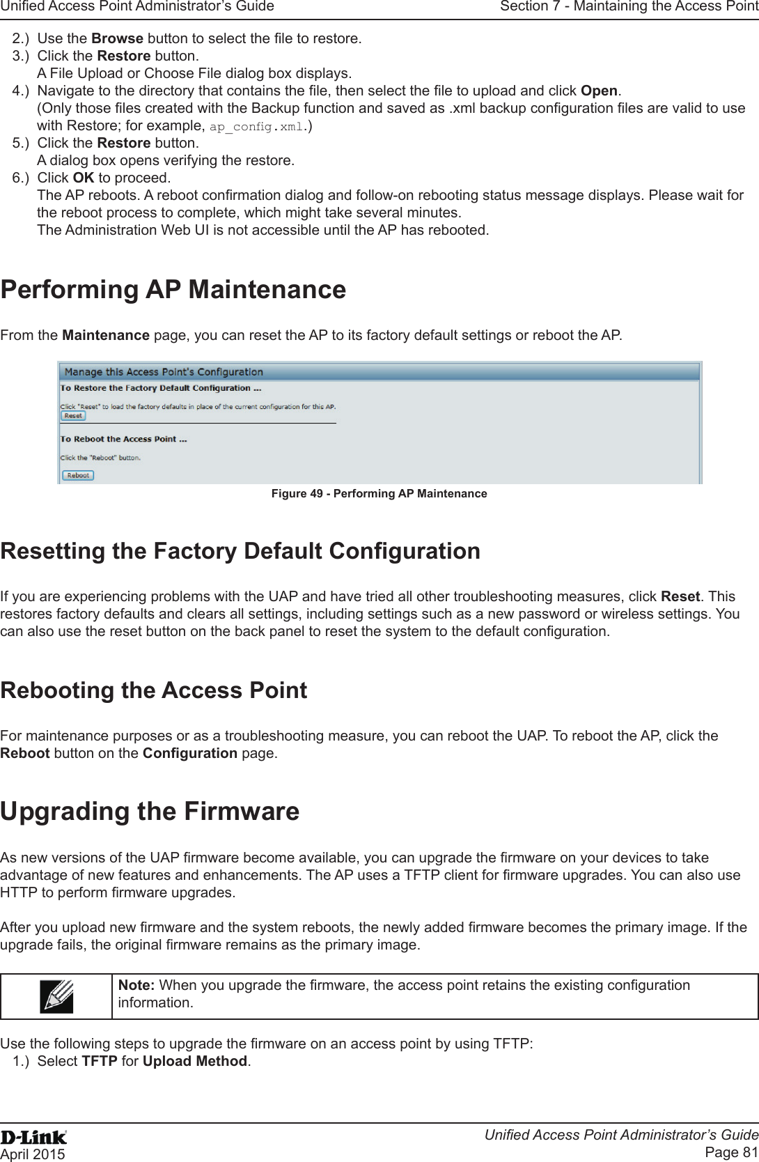
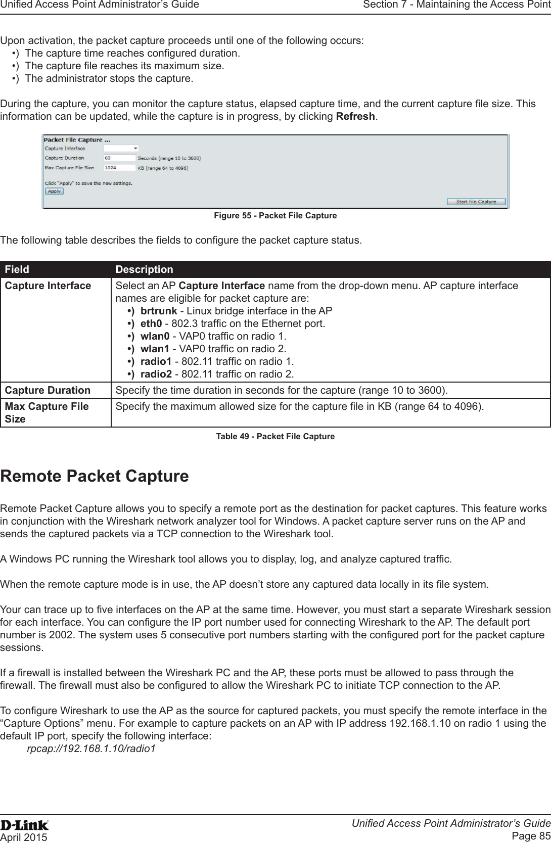
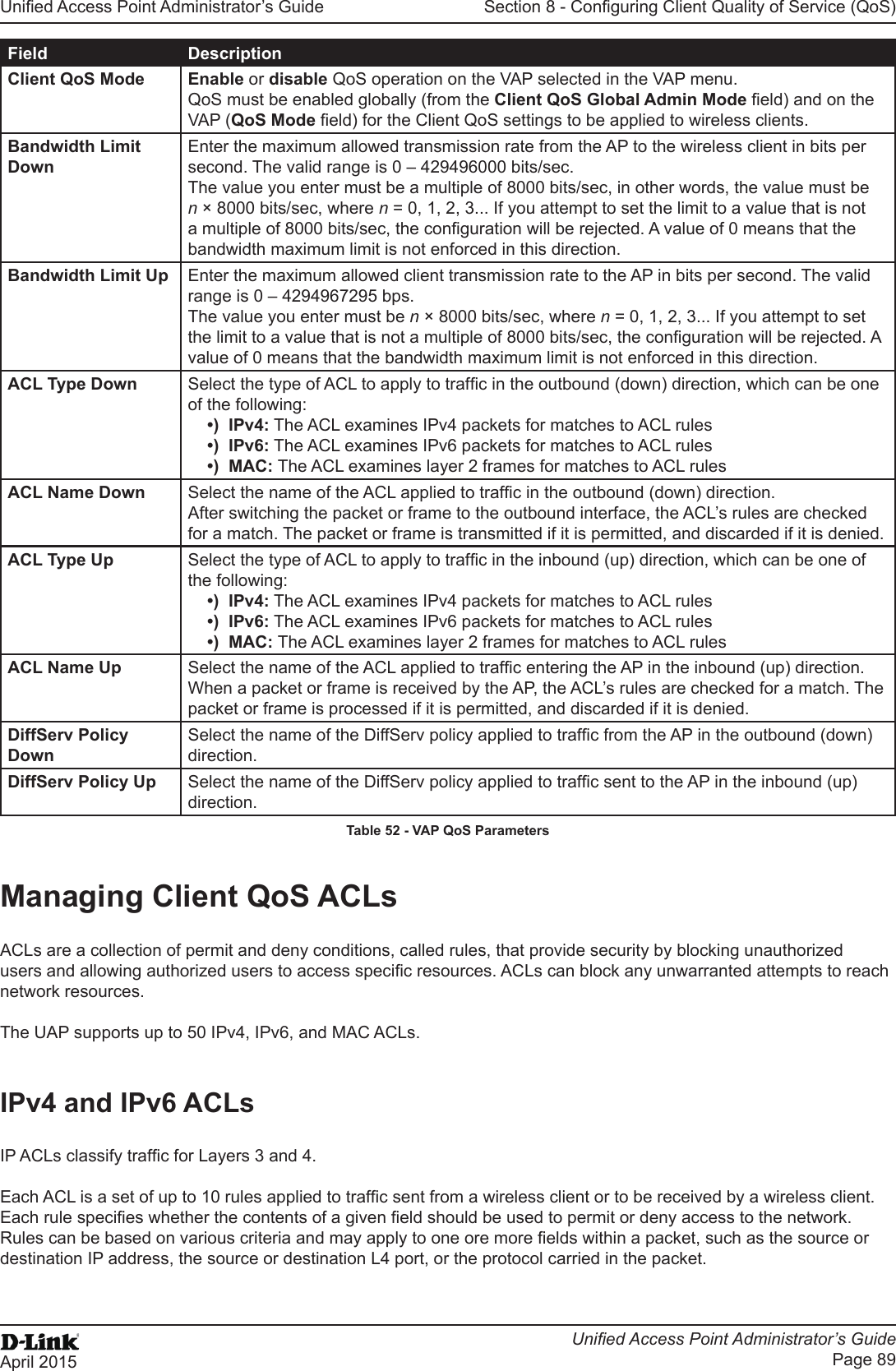
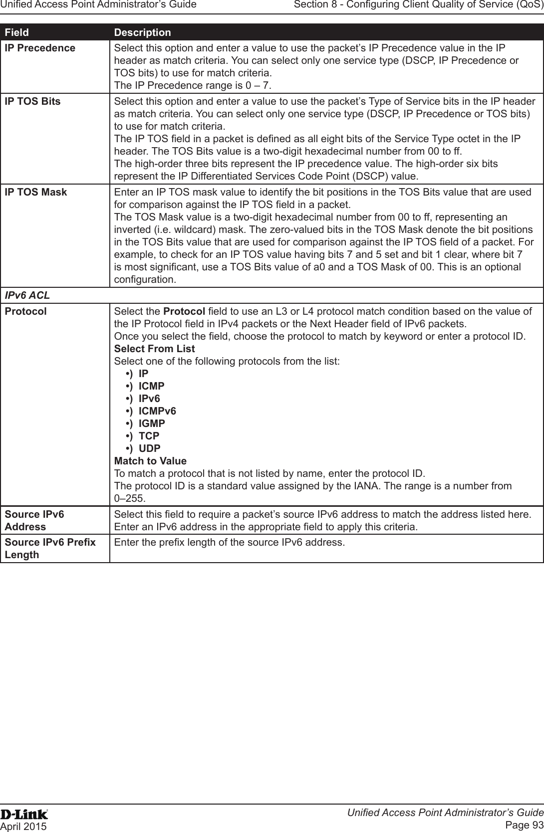
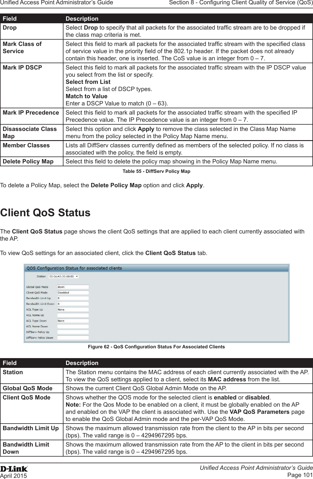
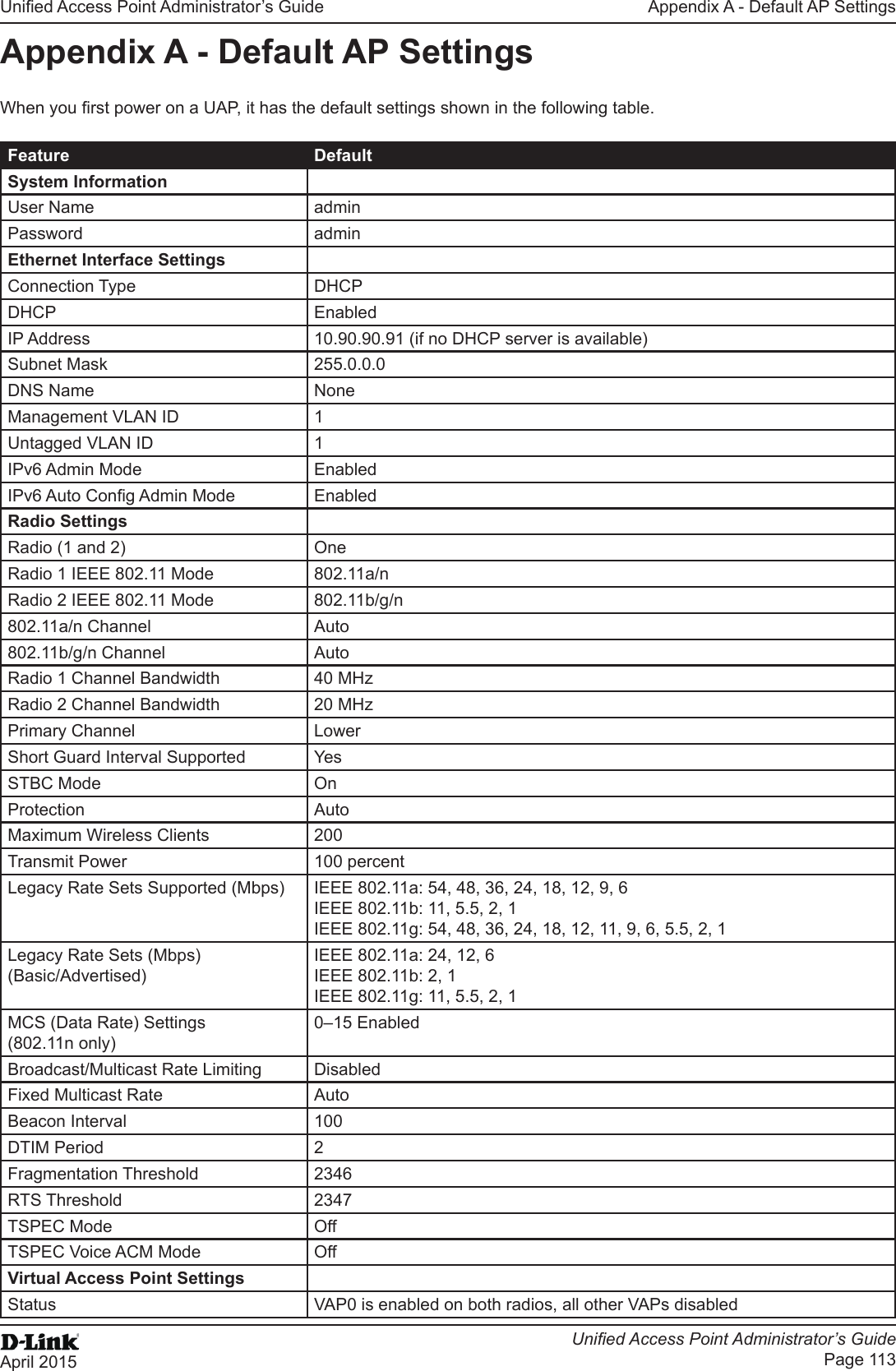
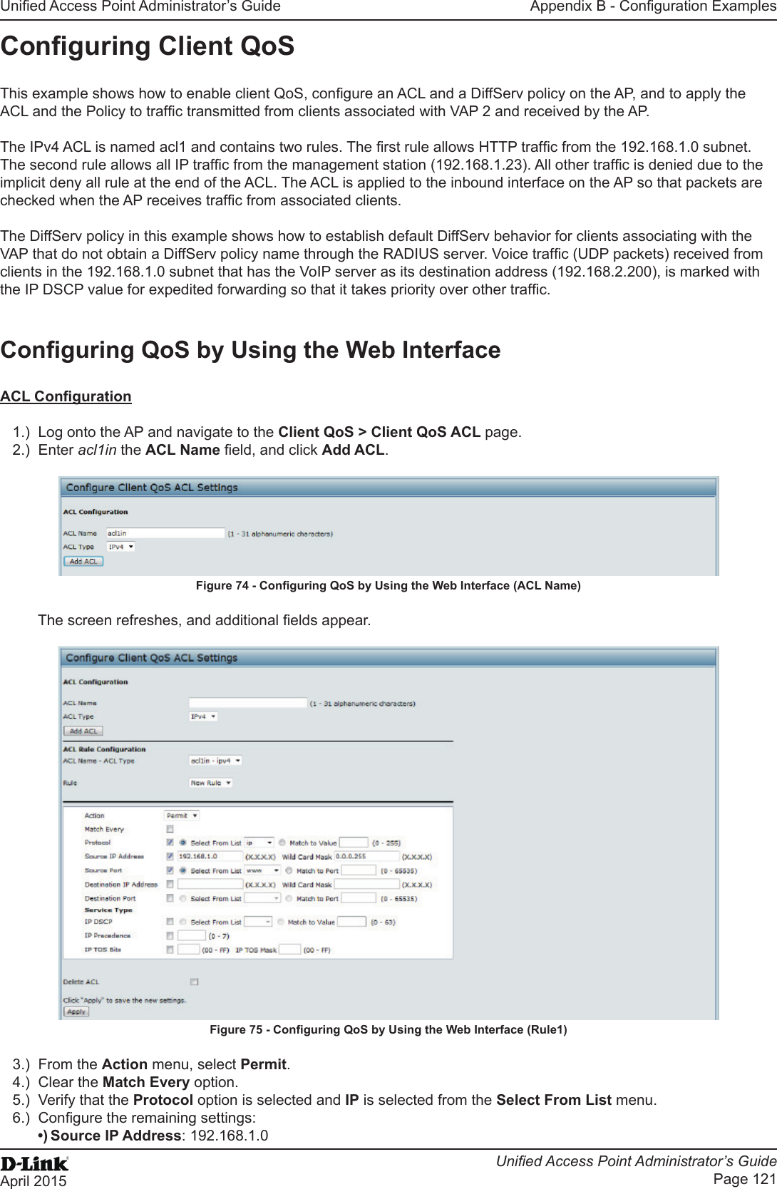
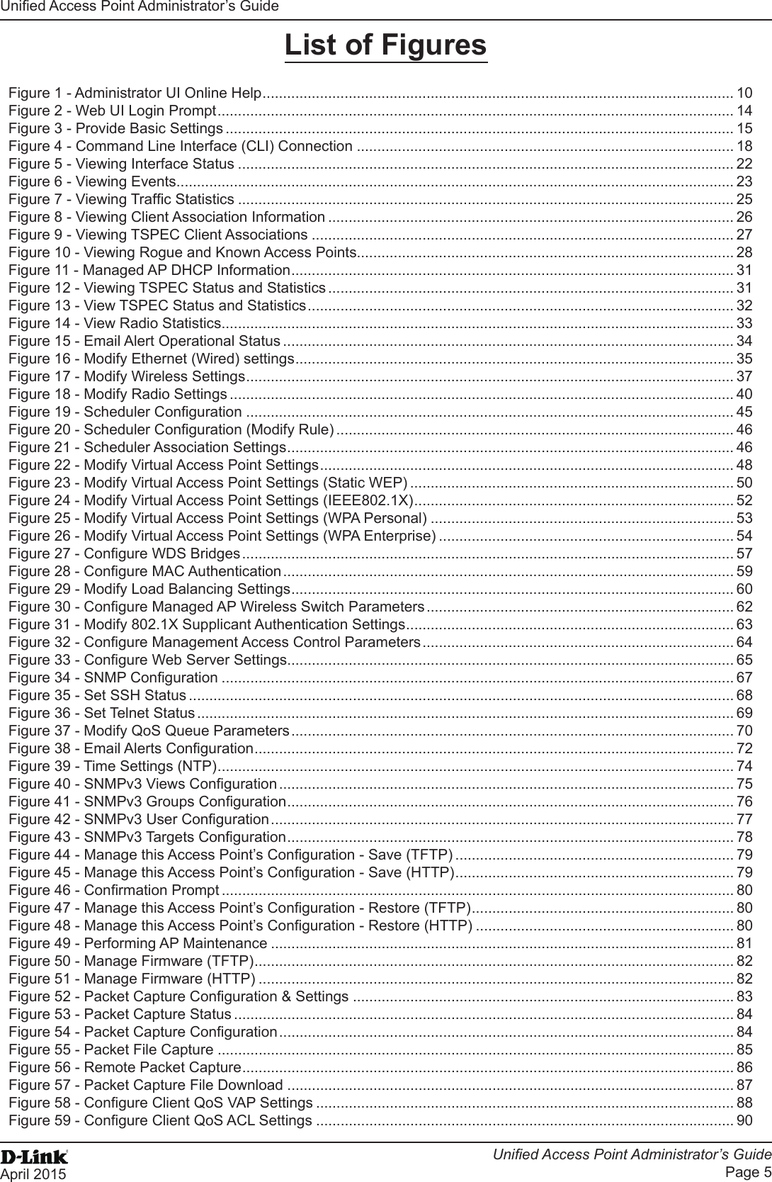
![Unied Access Point Administrator’s GuideUnied Access Point Administrator’s GuidePage 73April 2015Section 5 - Conguring Access Point ServicesField DescriptionNon Urgent Severity Congures the severity level for log messages that are considered to be non-urgent. Messages in this category are collected and sent in a digest form at the time interval specied by the Log Duration eld. The security level you select and all levels up to, but not including the lowest Urgent level are considered non-urgent. Messages below the security level you specify are not sent via email. See the Urgent Message eld description for information about the security levels.Email Alert Mail Server CongurationMail Server Address Specify the IP address or hostname of the SMTP server on the network.Mail Server Security Specify whether to use SMTP over SSL (TLSv1) or no security (Open) for authentication with the mail server. The default is Open.Mail Server Port Congures the TCP port number for SMTP. The range is a valid port number from 0 to 65535. The default is 25, which is the standard port for SMTP.Username Specify the username to use when authentication with the mail server is required. The username is a 64-byte character string with all printable characters. The default is admin.Password Specify the password associated with the username congured in the previous eld.Email Alert Message CongurationTo Address 1 Congure the rst email address to which alert messages are sent. The address must be a valid email address. By default, no address is congured.To Address 2 Optionally, congure the second email address to which alert messages are sent. The address must be a valid email address. By default, no address is congured.To Address 3 Optionally, congure the third email address to which alert messages are sent. The address must be a valid email address. By default, no address is congured.Email Subject Specify the text to be displayed in the subject of the email alert message. The subject can contain up to 255 alphanumeric characters. The default is Log message from AP.Table 41 - Email Alert CongurationNote: After you congure the Email Alert settings, click Apply to apply the changes and to save the settings. To validate the congured email server credentials, click Test Mail. You can send a test email once the email server details are congured.The following text shows an example of an email alert sent from the AP to the network administrator:From: AP-192.168.2.10@mailserver.com Sent: Wednesday, July 08, 2011 11:16 AMTo: administrator@mailserver.comSubject: log message from APTIME Priority Process Id MessageJul 8 03:48:25 info login[1457] root login on ‘ttyp0’Jul 8 03:48:26 info mini_http-ssl[1175] Max concurrent connections of 20 reachedEnabling the Time Settings (NTP)Use the Time Settings page to specify the Network Time Protocol (NTP) server to use to provide time and date information to the AP or to congure the time and date information manually.NTP is an Internet standard protocol that synchronizes computer clock times on your network. NTP servers transmit Coordinated Universal Time (UTC, also known as Greenwich Mean Time) to their client systems. NTP sends periodic time requests to servers, using the returned time stamp to adjust its clock. The timestamp is used to indicate the date and time of each event in log messages.See http://www.ntp.org for more information about NTP.](https://usermanual.wiki/D-Link/WL6700APA1/User-Guide-2662295-Page-73.png)