D Link WL8710APA1 802.11n/ac Unified Wireless Outdoor Access Point User Manual rev
D Link Corporation 802.11n/ac Unified Wireless Outdoor Access Point rev
D Link >
User Manual_rev.pdf
Documentation is also available on
the CD and the D-Link website
This document will guide you through the basic installation
process for your new D-Link Access Point.
DWL-8710AP
Quick Installation Guide
2
ENGLISH
PowerPower
LAN1
LAN2
2.4GHz
5.0GHz
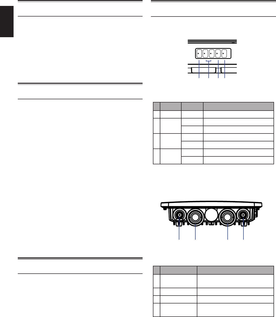
Hardware Overview
LED Indicators
Figure 1: Front panel LEDs
# LED Status Description
1Power On Device is powered and working
2LAN
1/2
Blinking Data is being processed
On Port is connected to a device
32.4 GHz Blinking Wireless data is being processed
On AP is transmitting over 2.4 GHz
45 GHz Blinking Wireless data is being processed
On AP is transmitting over 5 GHz
Table 1: LED overview
Bottom Interface Connectors
Figure 2: Bottom panel connectors
# Connector Description
15 GHz Antenna connector for the
5 GHz band antenna
2LAN 1 LAN and PoE input port
3LAN 2 Non-PoE LAN input port
42.4 GHz Antenna connector for the
2.4 GHz band antenna
Table 2: Connector description
Before You Begin
This Quick Installation Guide gives you step-by-
step instructions for setting up your DWL-8710AP
802.11n/ac Unied Wireless Outdoor Access Point.
The model you have purchased may appear slightly
dierent from the one shown in the illustrations. For
more detailed information about the access point,
conguring the device, and technical specications,
please refer to the User Manual.
Package Contents
This DWL-8710AP package should include the
following items:
• DWL-8710AP
• 4 antennas
• 4 antenna connector caps
• Single port PoE injector with power supply
• Grounding wire and screw
• Wall mounting base plate
• Pole mounting bracket
• Mounting kit (bolts, washers, nuts, screws, pole
strap)
• CD-ROM with documentation
To power the DWL-8710AP, please use any D-Link
IEEE 802.3at-compliant PoE switch or the D-Link
DPE-301GI PoE injector.
If any of the above items are damaged or missing,
please contact your local D-Link reseller.
System Requirements
• CD-ROM drive
• Computer with Windows, Macintosh, or Linux-
based operating system
• Installed and operational Ethernet adapter
• Internet Explorer 6.0, Chrome 2.0, Safari 2.0, or
Firefox 3.0 and above
123 4
1 2 3 4
3
ENGLISH
Hardware Installation
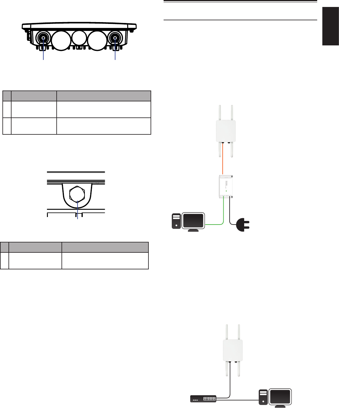
Powering the Access Point
You can power the DWL-8710AP by connecting a PoE
injector’s PoE-OUT to the LAN1 port (PoE-Input) on
the DWL-8710AP. Then connect the PoE injector’s
LAN-IN port to an available Ethernet port on your
computer and plug in the injector’s power cord into
a power outlet as shown in gure 5.
Figure 5: Powering with a PoE injector
Alternatively, you may directly connect the LAN1
(PoE-Input) port on the DWL-8710AP to any available
PoE-capable port of an 802.3at-compliant PoE
switch, as illustrated in gure 6.
Figure 6: Direct PoE powering
Top Interface Connectors
Figure 3: Top panel connectors
# Connector Description
15 GHz Antenna connector for the
5 GHz band antenna
22.4 GHz Antenna connector for the
2.4 GHz band antenna
Table 3: Top connector description
Side Panel
Figure 4: Side panel vent
#Item Description
1GORE® Vent Repels liquid and particles while
allowing air to pass through
Table 4: Vent description
1 2
1
Connect LAN1 on the
DWL-8710AP to the
Ethernet port labeled PoE
OUT on the PoE injector
DWL-8710AP
Connect a computer to the
Ethernet port labeled LAN
IN on the PoE injector
PoE Out
Connect the power
adapter to the PoE injector
and a power outlet
Computer Power In
54V INLAN IN
DWL-8710AP
ComputerPoE Switch
4
ENGLISH
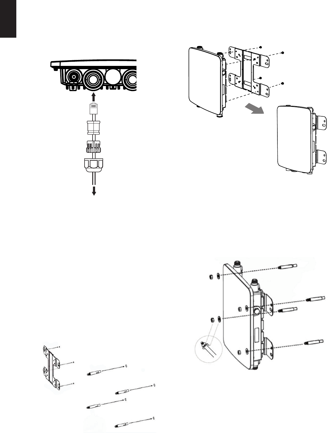
Protecting the Network Ports
The DWL-8710AP’s Ethernet ports are equipped
with a set of protective sealing caps designed for
outdoor use. Please refer to figure 7 for how to
correctly attach and secure the Ethernet cables to
the DWL-8710AP.
Figure 7: Securing the Ethernet cable
Mounting the AP to a Wall
The DWL-8710AP can be mounted either horizontally
or vertically. However, it is recommended that the AP
is installed with the antennas positioned vertically
in order to achieve optimal performance.
1. Use the mounting base plate to mark the location
on the surface where you want to mount the
DWL-8710AP. Next, drill a hole of 8 mm wide and
37 mm deep on all 4 markings.
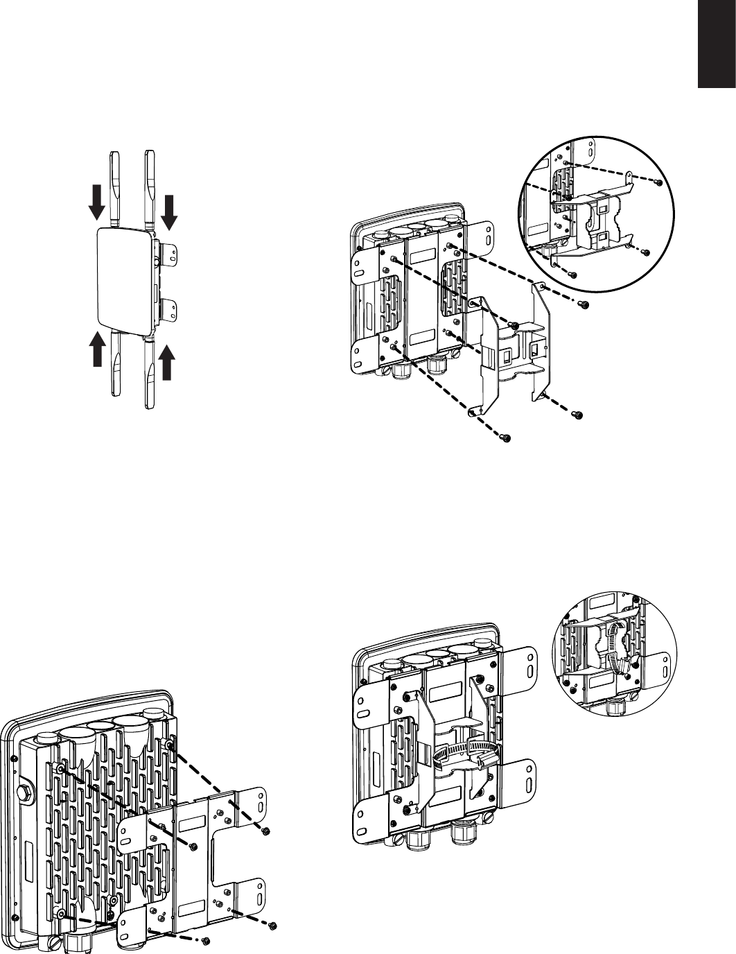
2. Remove the nut and washer from the bolts and
place the bolts in the holes as shown below in
gure 8.
Figure 8: Preparing the mounting location
3. Place and lock the at washer on the cap screws
and attach the mounting plate to the back of
the DWL-8710AP using the screws as illustrated
in gure 9.
Figure 9: Mounting the base plate
4. Mount the DWL-8710AP onto the bolts that
were placed in the wall, then fasten the bolts’ at
washers and nuts to secure the mounting plate
with the AP to the wall surface.
Figure 10: Securing the AP
5
ENGLISH
5. Remove the protective caps covering the
antenna ports on the AP, if any. Next, connect the
2 antennas marked “2.4 GHz” to the designated
2.4 GHz connectors and the antennas marked
“5 GHz” to the designated 5 GHz connectors
on the AP. The DWL-8710AP is now ready to be
connected to the network.
Figure 11: Attaching the antennas
Mounting the AP to a Pole
The DWL-8710AP can be mounted either horizontally
or vertically. However, it is recommended that the AP
is installed with the antennas positioned vertically
in order to achieve optimal performance.
1. Place the lock and at washer on the cap screws
and attach the mounting plate to the back of the
DWL-8710AP.
Figure 12: Mounting the base plate
2. Depending on the orientation of the pole
you wish to install the AP onto (horizontal or
vertical), attach the pole mounting bracket to
the mounting base plate accordingly using the
screws. Refer to gure 13 for the proper position
of the pole mounting bracket for each direction.
Figure 13: Attaching the pole mount base
3. Thread the open end of the pole strap through
the two tabs on the pole mounting bracket to
secure the strap to the mounting bracket.
Figure 14: Attaching the pole strap
6
ENGLISH
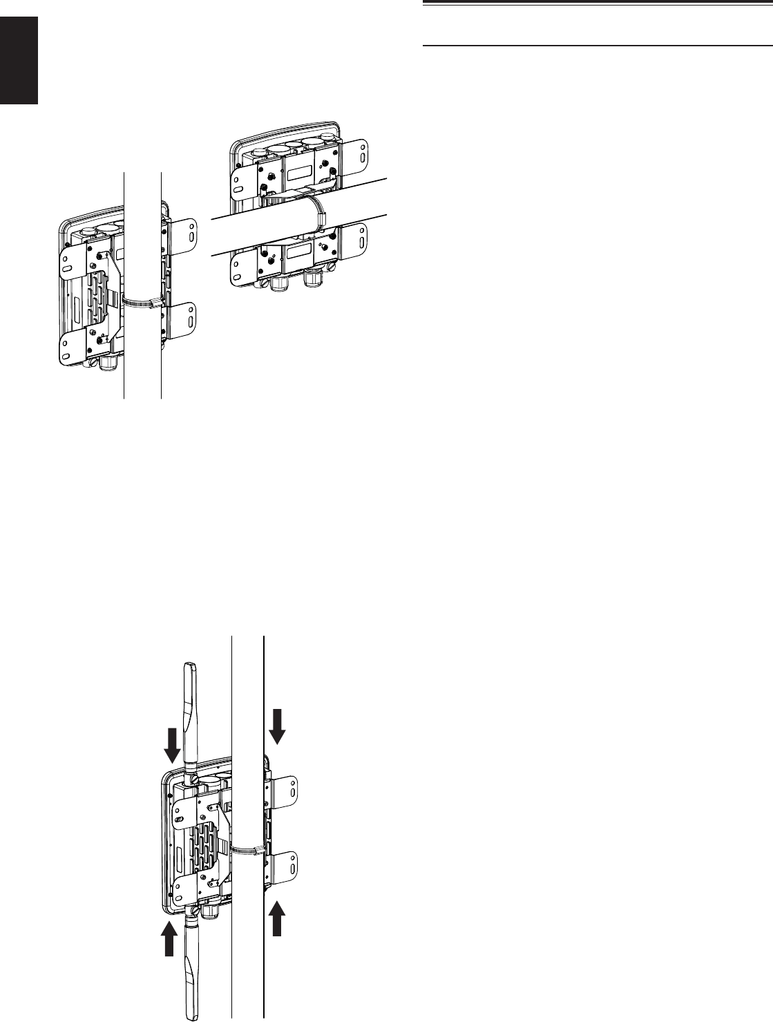
4. Choose the location where you want to mount
the AP and place the strap around the pole.
Tighten and lock the strap to secure the pole
mount bracket with the AP to the pole.
Figure 15: AP placement orientation
5. Remove the protective caps covering the
antenna ports on the AP, if any. Next, attach the
2 antennas marked “2.4 GHz” to the designated
2.4 GHz connectors and the 2 antennas marked
“5 GHz” to the designated 5 GHz connectors
on the AP. The DWL-8710AP is now ready to be
connected to the network.
Figure 16: Attaching the antennas
Conguring the Access Point
To congure the DWL-8710AP, simply connect the
AP directly to a computer and congure it through
its Graphical User Interface (GUI).
For more detailed information on how to set up and
congure the DWL-8710AP, please refer to the User
Manual.

Federal Communication Commission
Interference Statement
This equipment has been tested and found to comply
with the limits for a Class B digital device, pursuant to Part
15 of the FCC Rules. These limits are designed to provide
reasonable protection against harmful interference in
a residential installation. This equipment generates,
uses and can radiate radio frequency energy and, if not
installed and used in accordance with the instructions,
may cause harmful interference to radio communications.
However, there is no guarantee that interference will not
occur in a particular installation. If this equipment does
cause harmful interference to radio or television reception,
which can be determined by turning the equipment
o and on, the user is encouraged to try to correct the
interference by one of the following measures:
• Reorient or relocate the receiving antenna.
• Increase the separation between the equipment
and receiver.
• Connect the equipment into an outlet on a
circuit dierent from that to which the receiver is
connected.
• Consult the dealer or an experienced radio/TV
technician for help.
FCC Caution: Any changes or modications not expressly
approved by the party responsible for compliance could
void the user’s authority to operate this equipment.
This device complies with Part 15 of the FCC Rules.
Operation is subject to the following two conditions: (1)
This device may not cause harmful interference, and (2) this
device must accept any interference received, including
interference that may cause undesired operation.
This transmitter must not be co-located or operating in
conjunction with any other antenna or transmitter.
IMPORTANT NOTE:
FCC Radiation Exposure Statement:
This equipment complies with FCC radiation exposure
limits set forth for an uncontrolled environment. This
equipment should be installed and operated with
minimum distance 24cm between the radiator & your
body.
Industry Canada statement:
This device complies with Industry Canada licence-exempt
RSS standard(s). Operation is subject to the following two
conditions: (1) this device may not cause interference, and
(2) this device must accept any interference, including
interference that may cause undesired operation of the
device.
Le présent appareil est conforme aux CNR d’Industrie
Canada applicables aux appareils radio exempts de
licence. L’exploitation est autorisée aux deux conditions
suivantes : (1) l’appareil ne doit pas produire de brouillage,
et (2) l’utilisateur de l’appareil doit accepter tout brouillage
radioélectrique subi, même si le brouillage est susceptible
d’en compromettre le fonctionnement.
Caution :
(i) the device for operation in the band 5150-5250 MHz
is only for indoor use to reduce the potential for harmful
interference to co-channel mobile satellite systems;
(ii) high-power radars are allocated as primary users (i.e.
priority users) of the bands 5250-5350 MHz and 5650-5850
MHz and that these radars could cause interference and/
or damage to LE-LAN devices.
Avertissement:
(i) les dispositifs fonctionnant dans la bande 5150-5250
MHz sont réservés uniquement pour une utilisation
à l’intérieur afin de réduire les risques de brouillage
préjudiciable aux systèmes de satellites mobiles utilisant
les mêmes canaux;
(ii) De plus, les utilisateurs devraient aussi être avisés que
les utilisateurs de radars de haute puissance sont désignés
utilisateurs principaux (c.-à-d., qu’ils ont la priorité) pour
les bandes 5250-5350 MHz et 5650-5850 MHz et que
ces radars pourraient causer du brouillage et/ou des
dommages aux dispositifs LAN-EL.
Radiation Exposure Statement:
This equipment complies with IC radiation exposure limits
set forth for an uncontrolled environment. This equipment
should be installed and operated with minimum distance
30cm ween the radiator & your body.
Déclaration d’exposition aux radiations:
Cet équipement est conforme aux limites d’exposition
aux rayonnements IC établies pour un environnement
non contrôlé. Cet équipement doit être installé et utilisé
avec un minimum de 30 cm de distance entre la source
de rayonnement et votre corps.
This radio transmitter (IC: 4216A-WL8710APA1) has been
approved by Industry Canada to operate with the antenna
types listed below with the maximum permissible gain
and required antenna impedance for each antenna type
indicated. Antenna types not included in this list, having
a gain greater than the maximum gain indicated for that
type, are strictly prohibited for use with this device.
Antenna information
Frequency Band Model Type Connector Gain(dBi)
2.4GHz Master Wave 95615MNXX003 Dipole N Plug 4.92
5GHz Master Wave 95615MNXX005 Dipole N Plug 6.92
Professional installation instruction (for FCC)
1. Installation personal
This product is designed for specific application and
needs to be installed by a qualied personal who has RF
and related rule knowledge. The general user shall not
attempt to install or change the setting.
2. Installation location
The product shall be installed at a location where the
radiating antenna can be kept 24cm from nearby person
in normal operation condition to meet regulatory RF
exposure requirement.
3. External antenna
Use only the antennas which have been approved by the
applicant. The non-approved antenna(s) may produce
unwanted spurious or excessive RF transmitting power
which may lead to the violation of FCC limit and is
prohibited.
4. Installation procedure
Please refer to user’s manual for the detail.
5. Warning
Please carefully select the installation position and make
sure that the nal output power does not exceed the limit
set force in relevant rules. The violation of the rule could
lead to serious federal penalty.
Professional installation instruction(for IC)
1. Installation personal
This product is designed for specific application and
needs to be installed by a qualied personal who has RF
and related rule knowledge. The general user shall not
attempt to install or change the setting.
2. Installation location
The product shall be installed at a location where the
radiating antenna can be kept 30cm from nearby person
in normal operation condition to meet regulatory RF
exposure requirement.
3. External antenna
Use only the antennas which have been approved
by the applicant. The non-approved antenna(s) may
produce unwanted spurious or excessive RF transmitting
power which may lead to the violation of IC limit and is
prohibited.
4. Installation procedure
Please refer to user’s manual for the detail.
5. Warning
Please carefully select the installation position and make
sure that the nal output power does not exceed the limit
set force in relevant rules. The violation of the rule could
lead to serious federal penalty.
Instructions d’installation professionnelle
1. Installation
Ce produit est destine a un usage specifique et doit
etre installe par un personnel qualifie maitrisant les
radiofrequences et les regles s’y rapportant. L’installation
et les reglages ne doivent pas etre modies par l’utilisateur
nal.
2. Emplacement d’installation
En usage normal, afin de respecter les exigences
reglementaires concernant l’exposition aux
radiofrequences, ce produit doit etre installe de facon a
respecter une distance de 30cm entre l’antenne emettrice
et les personnes.
3. Antenn externe.
Utiliser uniiquement les antennes approuvees par le
fabricant. L’utilisation d’autres antennes peut conduire
a un niveau de rayonnement essentiel ou non essentiel
depassant les niveaux limites denis par IC, ce qui est
interdit.
4. Procedure d’installation
Consulter le manuel d’utilisation.
5. Avertissement
Choisir avec soin la position d’installation et s’assurer
que la puissance de sortie ne depasse pas les limites en
vigueur. La violation de cette regle peut conduire a de
serieuses penalites federales.
低功率電波輻射性電機管理辦法
第十二條 經型式認證合格之低功率射頻電機,非經許
可,公司、商號或使用者均不得擅自變更頻率、加大
功率或變更原設計之特性及功能。
第十四條 低功率射頻電機之使用不得影響飛航安全及
干擾合法通信;經發現有干擾現象時,應立即停用,
並改善至無干擾時方得繼續使用。
前項合法通信,指依電信法規定作業之無線電通信。
低功率射頻電機須忍受合法通信或工業、科學及醫療
用電波輻射性電機設備之干擾。
電磁波曝露量MPE標準值1mW/cm2,本產品使用時建
議應距離人體 24 cm。

Ver. 1.00(WW)_90x130
2016/02/23