D Link WR810A1 DC-HSPA+ Le Petit Router User Manual DWR 810 UserMan
D Link Corporation DC-HSPA+ Le Petit Router DWR 810 UserMan
UserManual.wiki
>
D Link
>
WR810A1 User Manual
User Manual
Navigation menu
Upload a User Manual
Namespaces
Wiki Guide
HTML
PDF
Info
Views
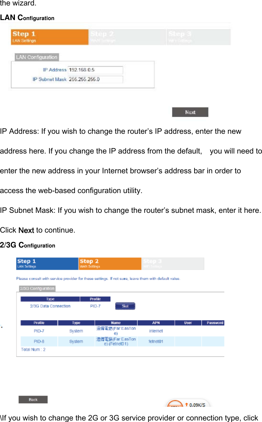
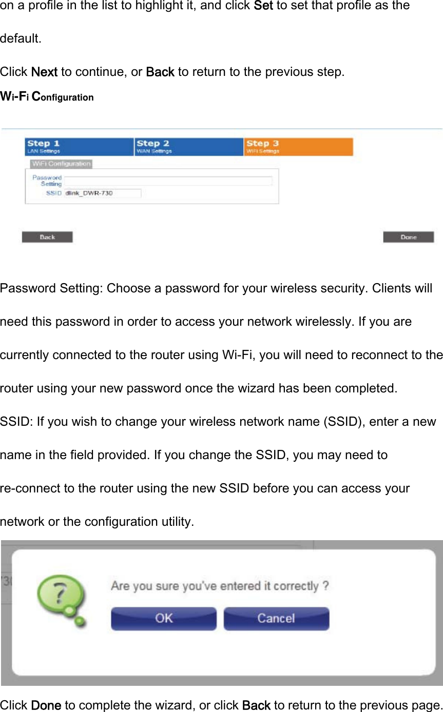
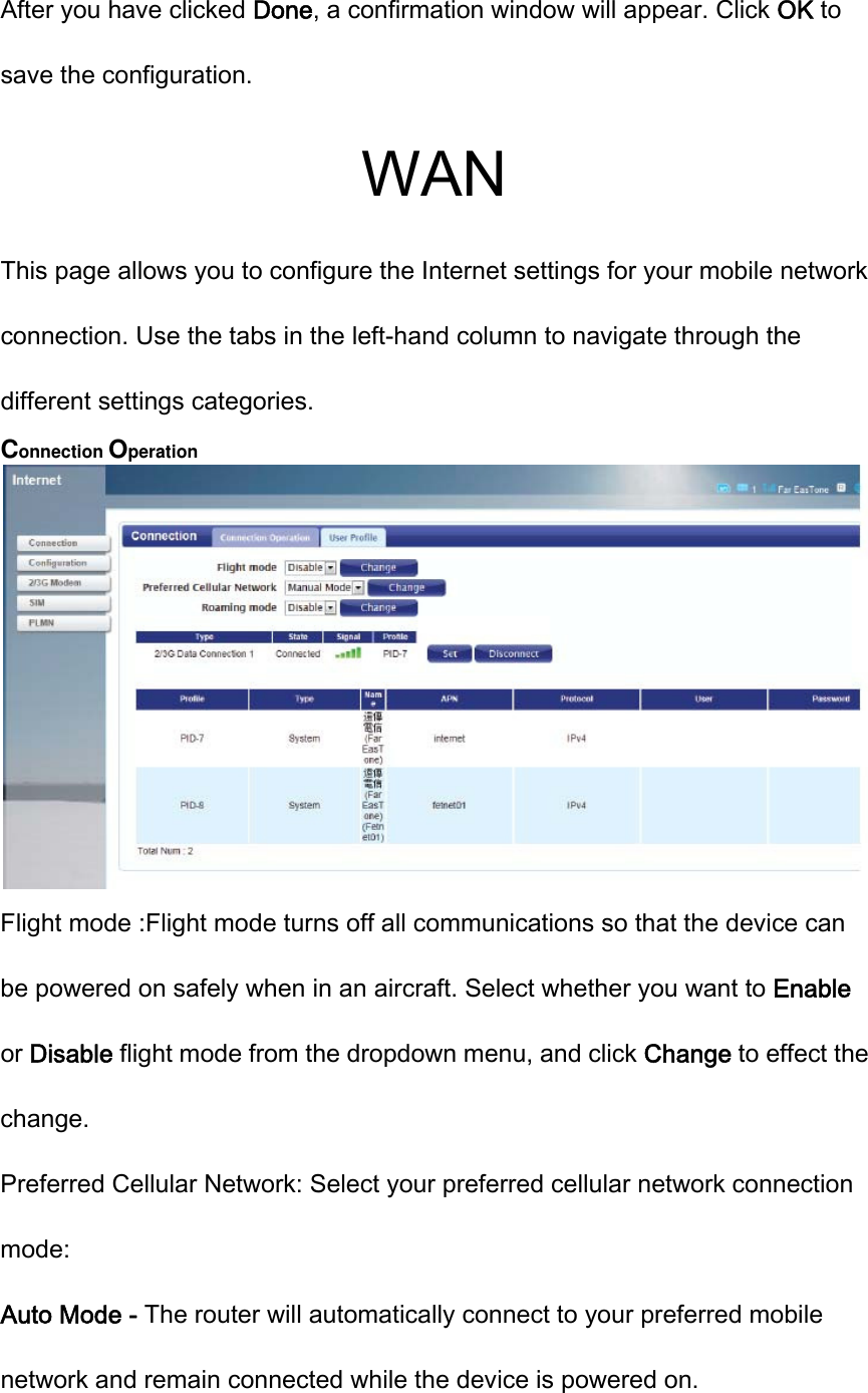
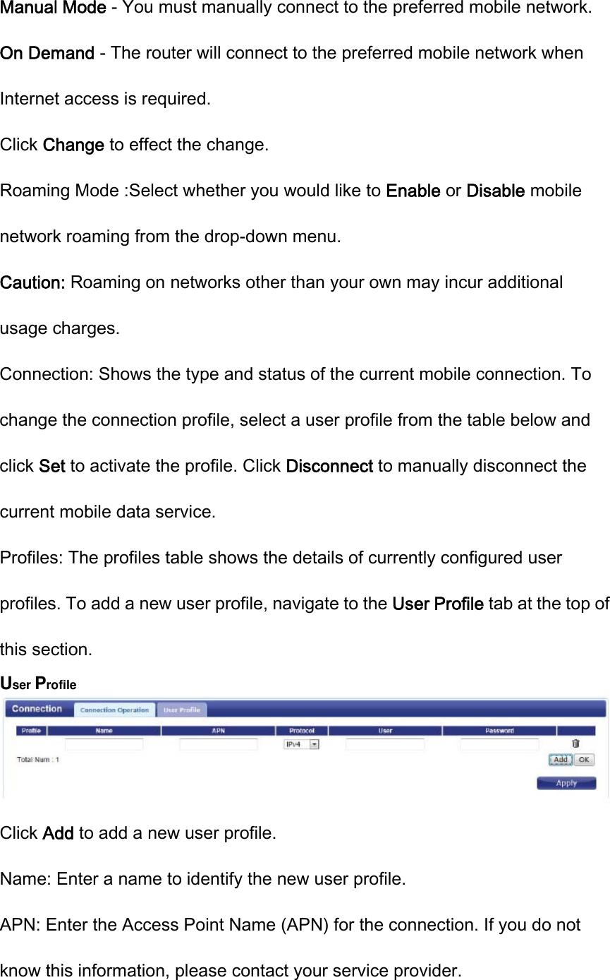
User Manual
Discussion / Help
Navigation