D Link XNW224A1 Wireless Ethernet Coax Bridge User Manual
D Link Corporation Wireless Ethernet Coax Bridge
D Link >
User Manual.pdf
WIRELESS ETHERNET COAXIAL BRIDGE
USER MANUAL
DXN-W224
Version 0.1
SYSTEM REQUIREMENTS
Windows 7 or XP , MAC OS
233MHz processor and at least 64MB of RAM
An available Ethernet Adapter (100Mbit/s)
PACKAGE CONTENTS
DXN-W224 Wireless Ethernet Bridge
CAT5 Ethernet cable
Power adapter
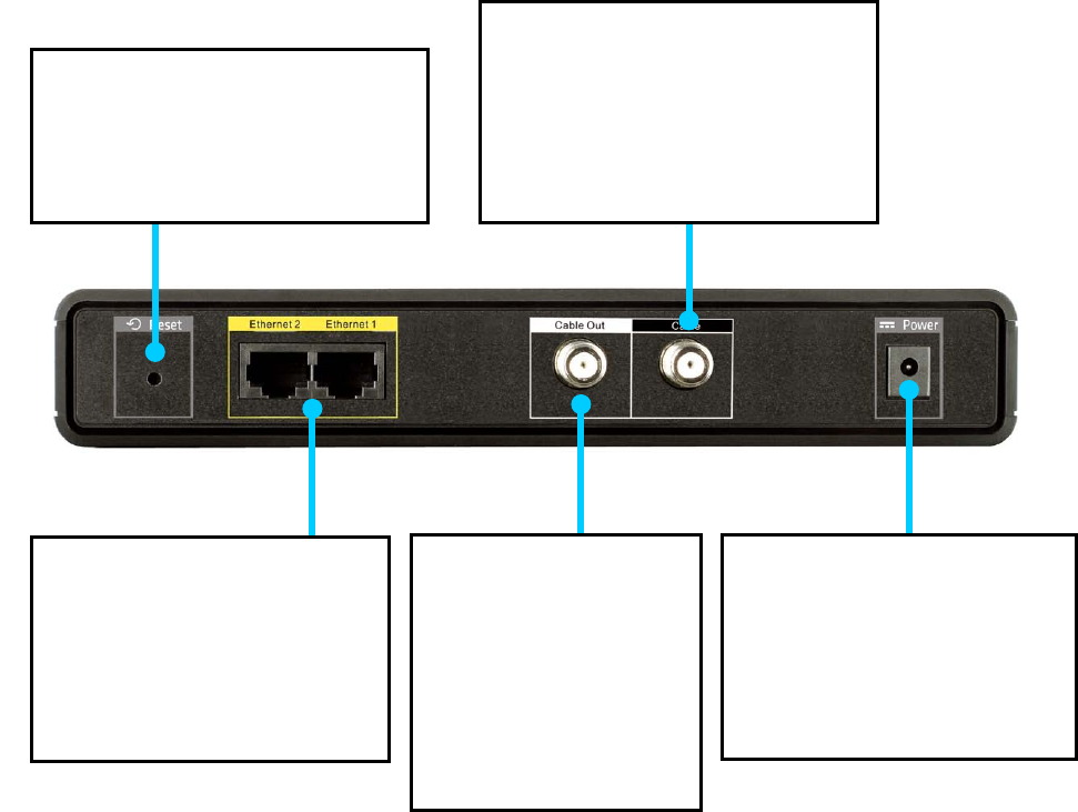
BACK PANEL
RESET
Press and hold at least 15
seconds to restore device back to
the factory default settings.
POWER
Connect the power adapter
included in the product
package of the DXN-W224.
LAN
Connect one end of the CAT5
Ethernet cable to DXN-W224
LAN port and the other end
to your Ethernet device.
CABLE OUT
Connect one end of a
coaxial cable to the
DXN-W224 TV out port
and the other end to
your television.
CABLE
Connect one end of a coaxial
cable to the DXN-W224 Coax
Input/Output port and the other
end to your cable outlet.
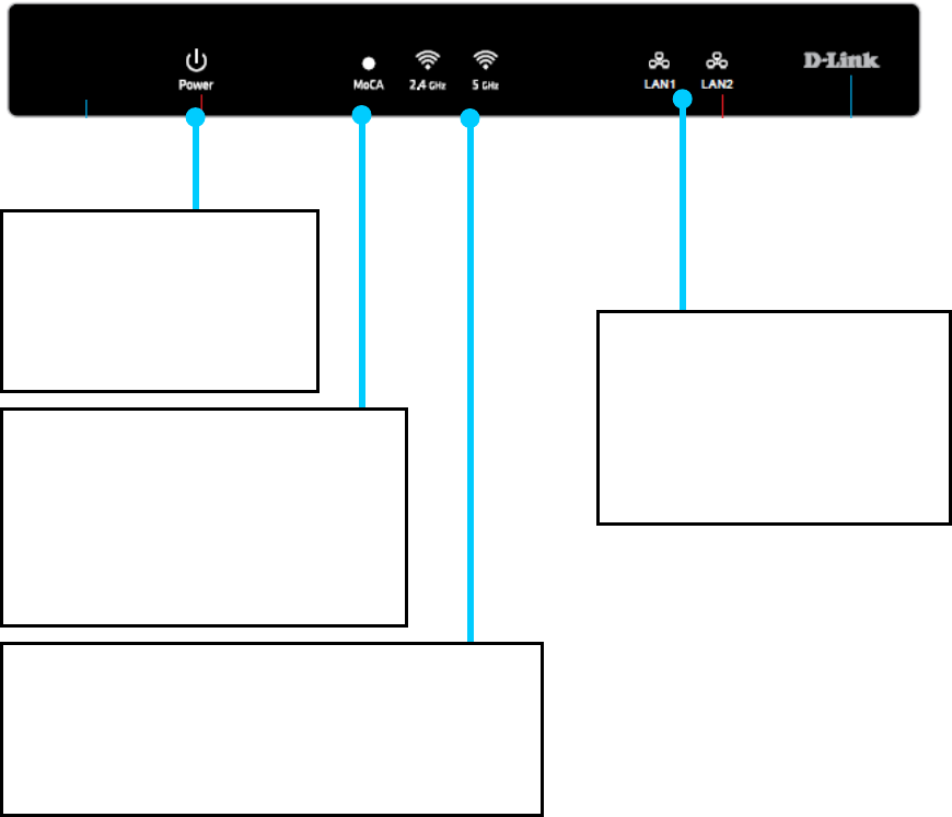
FRONT PANEL
POWER LED
A solid light indicates that
the device is receiving
power.
MOCA LED
A solid light indicates that the
device has formed a network over
the coaxial cable with at least one
other MoCA bridge.
2.4GHz/5GHz LED
A solid light indicates the wireless segment is
ready. The LED blinks during wireless data
transmission.
LAN LED
A solid light indicates that a
connection on the Ethernet
port. The LED blinks during
data transmission.
INSTALLATION PLANNING OVERVIEW
The proper cable installation, placement of filter/amplifier, frequency planning and
home preparation for signal coexistence should be planned out thoroughly before
deploying the DXN-W224
Inadequate planning will not only affect the DXN-W224 network but also cause
unwanted interference with other existing services. The following section discusses
these installation considerations in more detail.
Proper Cable Installation
The rooms qualified to be part of the DXN-W224 network should have an existing
coaxial connection and the following characteristics:
• The room is capable of receiving good quality analog television service
(no set-top box required) over the coaxial cable.
• The room is capable of receiving digital television services using a
set-top box.
If the room cannot receive digital or good quality analog television services, the
Ethernet-Coaxial network capabilities may be compromised to this location.
Amplifier Bypassing
An electronic amplifier is a device that boosts a weak signal. The typical amplifier
cannot pass DXN-W224 network signal because they are designed to be
unidirectional devices. Hence, the amplifier should be uninstalled or bypassed if
possible. To bypass an amplifier, user will need to install Diplexers to separate the
DXN-W224 signal and other signal first and only install the amplifier between the
paths of none DXN-W224 network signal.
Frequency Planning
The DXN-W224 is capable of operating between frequency bands of 1125MHz and
1525MHz. In order to avoid interference between the DXN-W224 device and other
devices on the same cable network, DXN-W224 device must operate at a frequency
spectrum that is different from other devices.
• 5-42MHz (Internet Access Upstream)
• 42-850MHz (Internet Access downstream)
• 50-806MHz (Off-Air TV)
• 50-860MHz (Cable TV)
• 950-2150MHz (Satellite L-Band)
One common scenario is where DXN-W224, cable television and high-speed Internet
service need to coexist. The cable television in United States operates between
50-860MHz while high-speed Internet service upstream and downstream operate
between 5-42MHz and 42-850 MHz respectively. Hence, the logical choice for
DXN-W224 frequency would be between 940-1500MHz. The similar frequencies
planning approach should be taken into consideration when dealing with Satellite
and off-air antenna.
Terrestrial Television (Off-Air)
If you are receiving terrestrial television service using a broadband antenna, then
additional components may have to be installed in order to be compliant with
governmental regulations. DXN-W224 network signals operating in the 1125 to 1525
MHz range should be prevented from radiating out of the antenna by using a small,
in-line Low Pass Filter(LPF-860Mhz). This filter will prevent DXN-W224 network
signals from reaching the antenna.
Cable Television (CATV)
For a cable television subscriber, there are no additional components required to
work with the DXN-W224 on the same cable network. The user may choose to install
the DXN-W224 on the network and use it as-is if data rate is acceptable. Else, user
may improve DXN-W224 network performance by inserting a Low Pass Filter
(LPF-860Mhz) at Point of Entry (POE) where the drop cable enters the house.
DBS Satellite Television with Terrestrial Television (Off-Air)
The Direct Broadcast Satellite (DBS) uses proprietary satellite channel-stacking
switch or Low-Noise Block (LNB) to distribute the resulting signal (usually 950 to
2150 MHz) in the same cable network that carries the lower-frequency terrestrial
television from an outdoor antenna. Another Diplexer then separates the signals to
the receiver of the TV set and the DBS set-top box (STB).
Most of the satellite switches are not designed to pass DXN-W224 network signal
and prevents it from forming a network. It is recommended that satellite signal and
DXN-W224 network signal should remain on separate cable networks. If separate
wiring cannot be done, then additional components have to be installed:
1. Install Triplexer to separate UHF/VHF, DXN-W224, and DBS signals.
2. Install MoCA Coupler switch before the satellite switch.
Existing OSP installed MoCA network
The DXN-W224 will automatically scan for an available channel and form
Ethernet-Coaxial network. This may cause issue with the existing OSP MoCA network.
It will not be permitted to join the OSP MoCA network unless utilizing the same
frequency and password.
The remedy in this situation is to use the DXN-W224 software utility to configure the
DXN-W224 to be on the same frequency with the same privacy network as the
existing OSP MoCA network.
HARDWARE INSTALLATION
Power
Plug the DXN-W224 into an AC wall outlet or power strip.
Note: Power source is confirmed when the green LED Power indicator on the
DXN-W224 is illuminated.
Connect the Ethernet Cable
Connect the included Ethernet cable to the LAN port located on the DXN-W224 and
attached the other end of the Ethernet cable to the network or PC.
Connect the Coaxial Cable
Connect coaxial cable to the Coax I/O port located on DXN-W224 and attached the
other end of the coax cable to your cable jack inside the house.
Note: Please make sure the DXN-W224’s configuration switch is in
MoCA mode. Coaxial Network Connectivity is confirmed when the green LED COAX
indicator on the DXN-W224 is illuminated.
If there is TV service being received in the room and you wish to continue viewing
the service, connect the other coax cable to the TV Out port on the DXN-W224 and
attach the other end of the coax cable to your television, Set-top Box (STB), or VCR
as desired.
SOFTWARE INSTALLATION
D-Link DXN-224 comes with software web-based configuration to allow
control over certain coaxial networking parameter. The unit is shipped
with default parameters that will allow operation on most coaxial
network without any additional configuration.
However, if a special network security password is required or if a
specific channel operating frequencies is required, then the default
parameters will need to be modified.
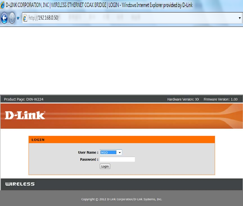
Web-based Configuration Utility
To access the configuration utility, open a web-browser such as Internet Explorer
and enter the IP address of the router (192.168.0.50).
Select any one of user name from the drop-down menu and then enter your
password as below.
User name: MSO, Technician or User
Password: [leave this blank by default]
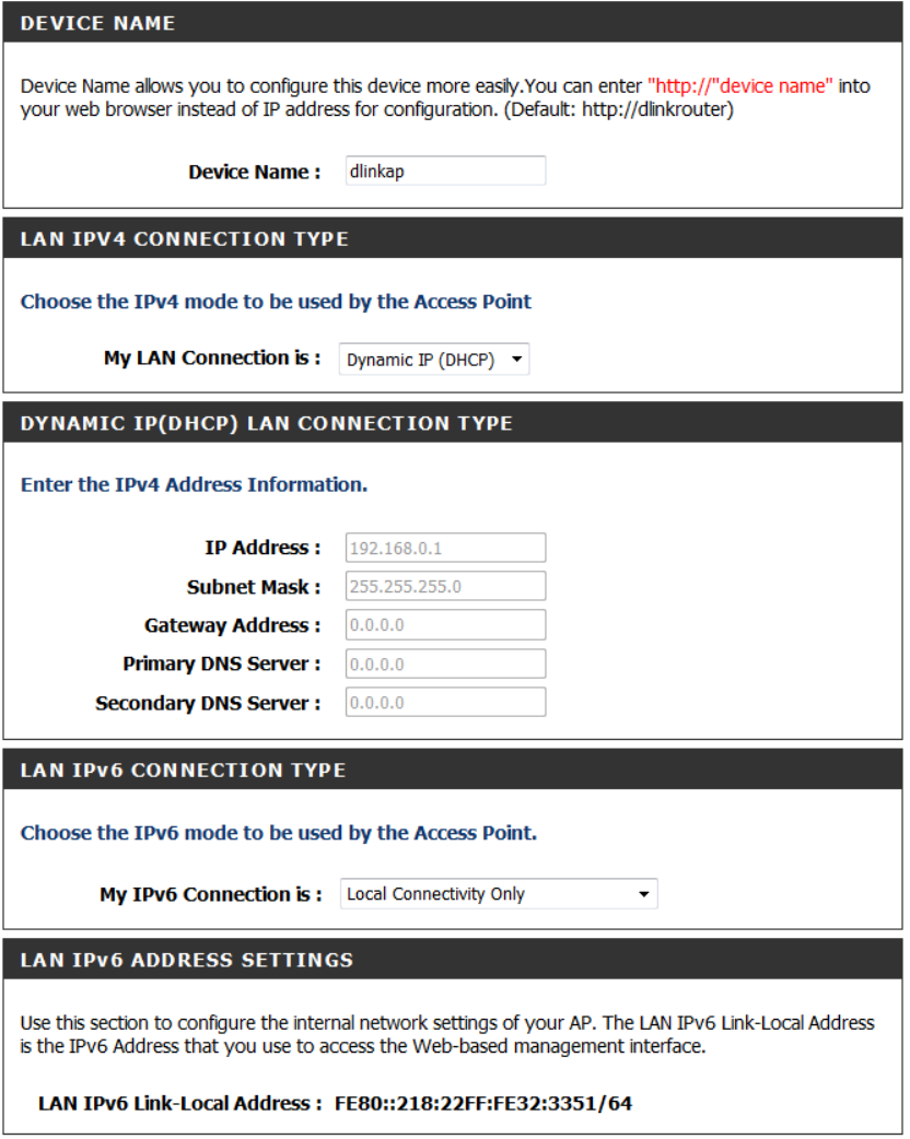
LAN Settings
Internet Setup –Dynamic IP
My LAN connection: Select Dynamic IP (DHCP) to obtain IP Address information
automatically from your ISP. Select this option if your ISP does not give you any IP
numbers to use. This option is commonly used for cable modem services such as
Comcast and Cox.
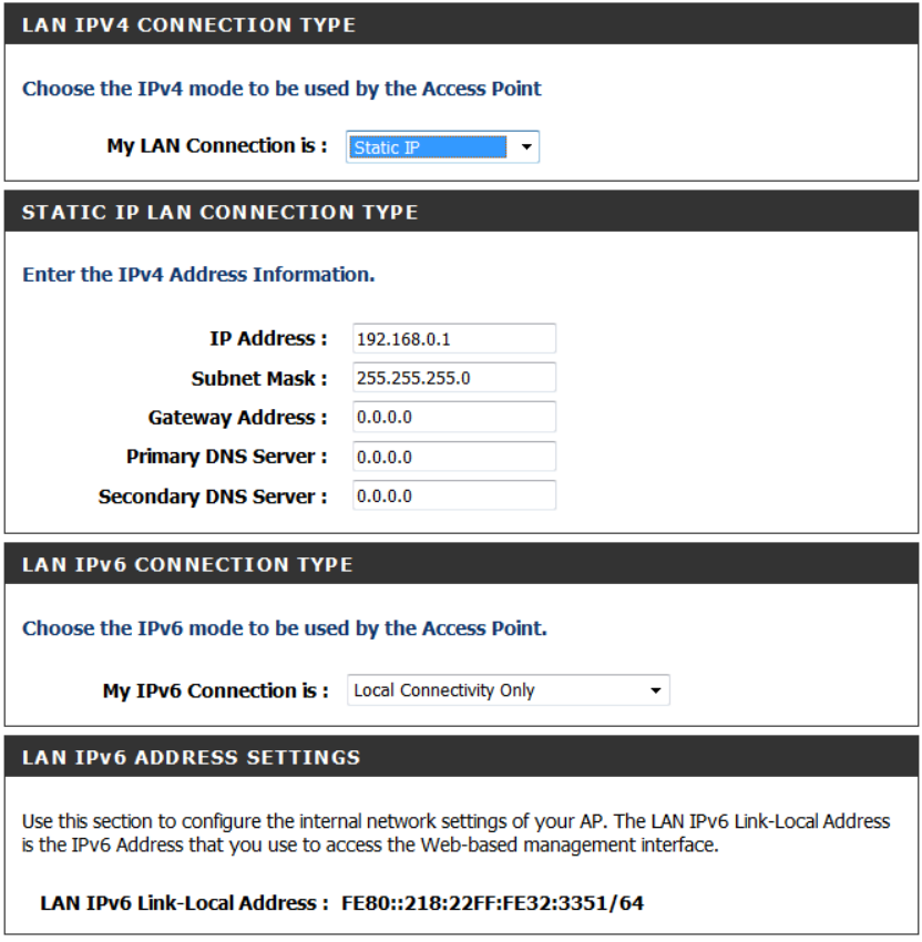
Internet Setup-Static (assigned by ISP)
Select Static IP Address if all the Internet port’s IP information is provided to you by
your ISP. You will need to enter in the IP address, subnet mask, gateway address,
and DNS address(es) provided to you by your ISP. Each IP address entered in the
fields must be in the appropriate IP form, which are four octets separated by a dot
(x.x.x.x). The Router will not accept the IP address if it is not in this format.
IP Address: Enter the IP address assigned by your ISP.
Subnet Mask: Enter the Subnet Mask assigned by your ISP.
Default Gateway: Enter the Gateway assigned by your ISP.
DNS Servers: The DNS server information will be supplied by your ISP
IPv6 Connection type:
If you select “LOCAL Connectivity Only”:
The user may see the LAN IPv6 Link-local address in the following section. It’s the
IPv6 address that you can use to access the web-based management interface. The
user can configure the IPv6 local settings.
The Link-local address is used by nodes and routers when communicating with
neighboring nodes on the same link. This mode enables IPv6-capable devices to
communicate with each other on the LAN side.
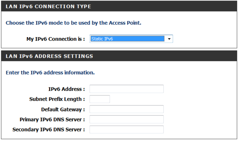
If you select” Static IPv6”:
IPv6 Address: Enter the IP address supplied by your ISP (Internet service provider).
Subnet Prefix length: Enter the value used here. This subnet supported with prefix
/64 is supported in LAN.
Default gateway: Enter the info provided by your ISP.
Primary IPv6 DNS server: Enter the info provided by your ISP.
Secondary IPv6 DNS server: Enter the info provided by your ISP
If you select “AutoConfiguration (SLAAC/DHCPv6)”:
DXN-W224 can automatically assign IPv6 address through SLAAC/DHCPv6 (Stateless
Address AutoConfiguration) this option.
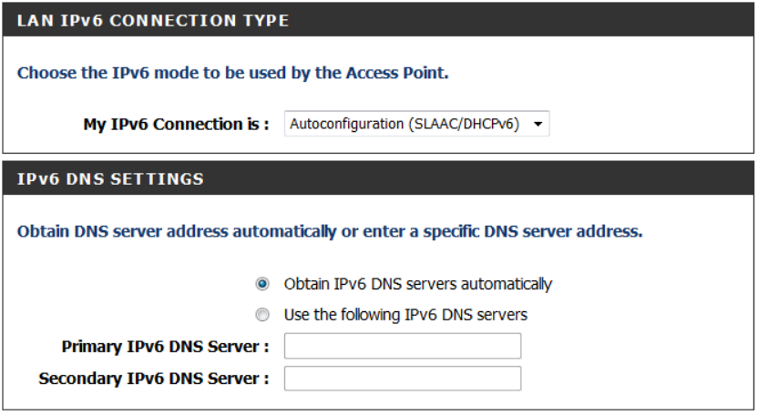
The user can select “obtain IPv6 DNS server automatically” and the DHCPv6 server will assign the
DNS server address automatically.
Or the user may manually enter the specific DNS server address through “Use the following IPv6
DNS server”
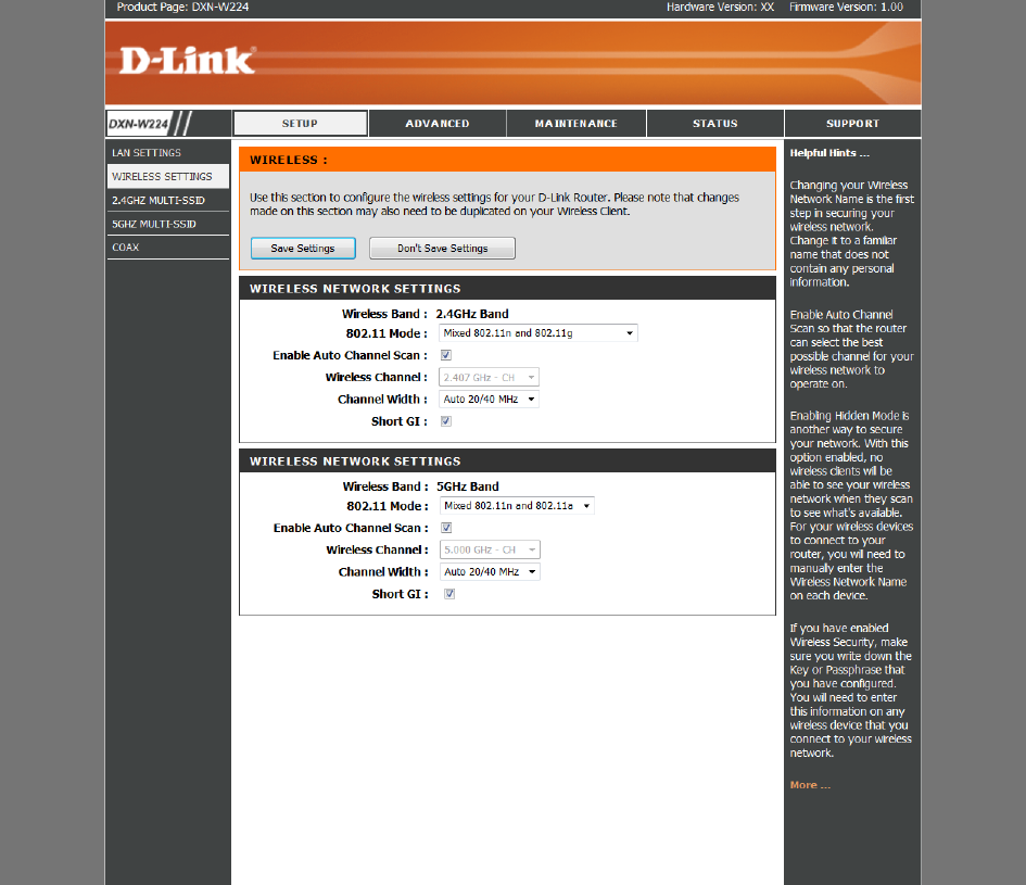
Wireless Settings
This section provides the users to configure the settings of 2.4GHz and 5GHz wireless
networks.
802.11mode Select one of the following:
802.11g Only - Select if all of your wireless clients are 802.11g.
Mixed 802.11n and 802.11g - Select if you are using both 802.11n and 802.11g wireless
clients.
802.11n Only - Select only if all of your wireless clients are 802.11n.
802.11b is not suggested to use unless the user has specific preferences.
Enable Auto Channel Scan: The Auto Channel Scan setting can be selected to allow the
DXN-W224 to choose the channel with the least amount of interference.
Wireless Channel: Indicates the channel setting for the DXN-W224. By default the
channel is set to 6. The Channel can be changed to fit the channel setting for an existing
wireless network or to customize the wireless network. If you enable Auto Channel Scan,
this option will be greyed out.
Channel Width: default is auto mode (HT20/40). This is used for the scenario when you
have both 11n and non-11n devices.
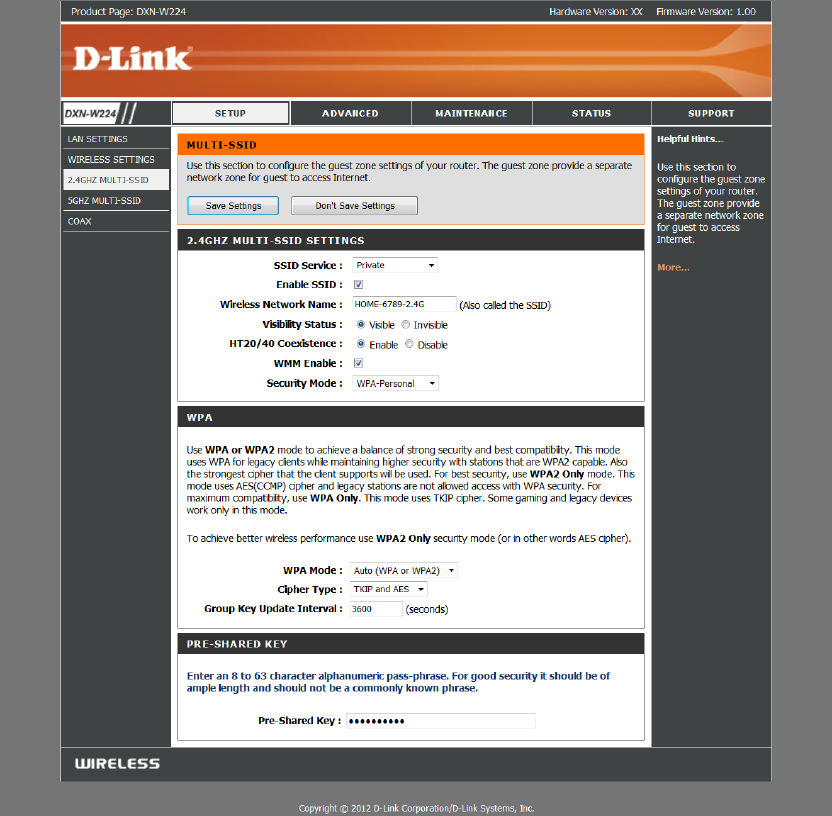
2.4GHz/5 G H z Multi-SSID
SSID Service: There four options-“Private”, “Home security”, “Home hotspot”, “future
service” for users to select the appropriate settings for specific SSID.
Enable SSID: Check the box to enable the service.
Wireless Network name: The user may provide a SSID name in this option.
Visibility Status: Select the options to allow the SSID is open to wireless clients.
Default is “Visible”. You may configure to “Invisible” that your SSID will not be
broadcasted by DXN-W224.
HT20/40 Coexistence: The default is HT20/40 coexist. Enable this to allow connection
for both 11n or non-11n wireless devices.
WMM enable: Check this box to allow the
WPA: Support the security to protect your wireless network from unsecure access.
Enter the security settings and pre shared key in this section.
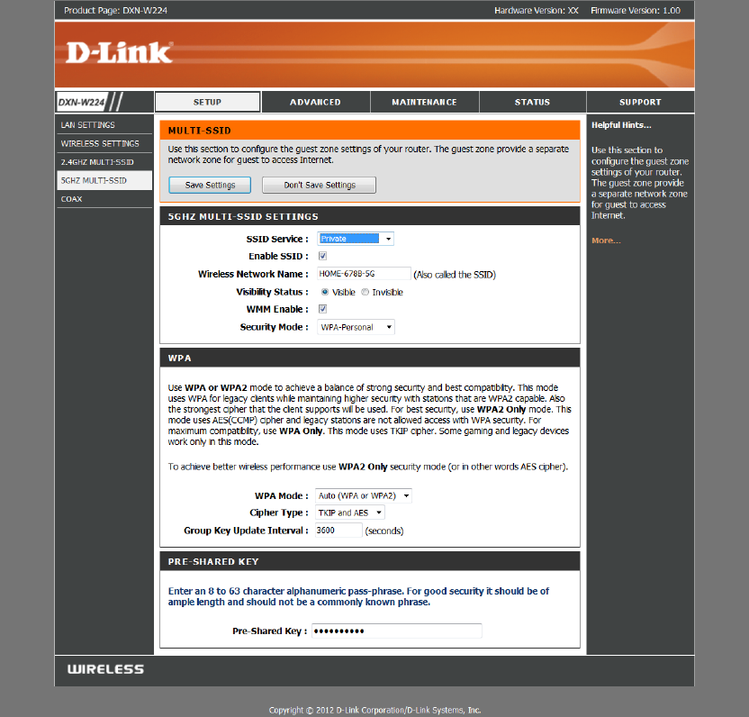
5GHz Multi-SSID
Please reference the 2.4Ghz multi SSID configuration.
D-LINK DXN-W224 MANUAL 18
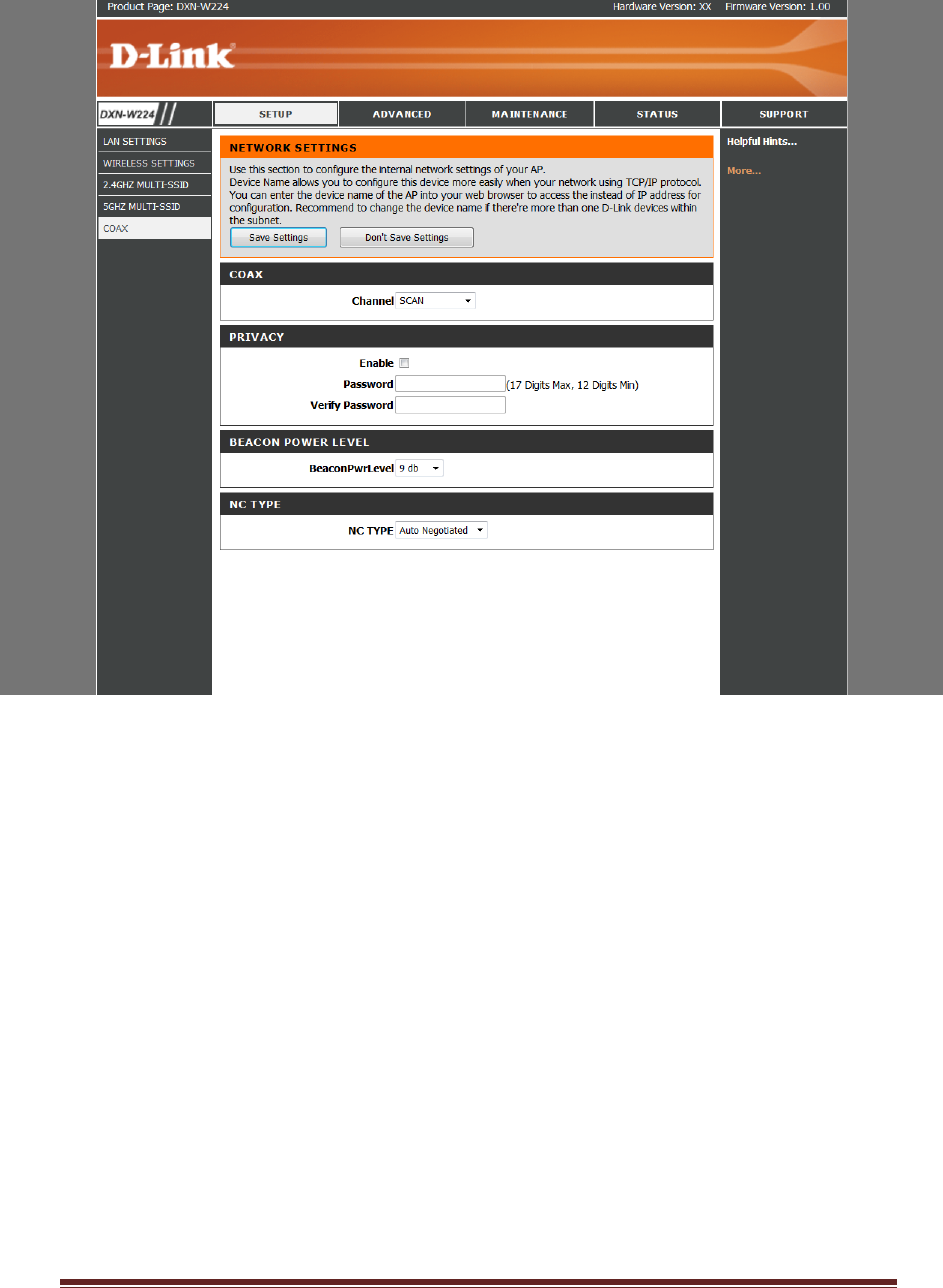
COAX Configuration
This section allows the user to configure the COAX network and privacy settings.
Channel: Select the specific channel frequency to use or select “SCAN” to
automatically scan for available channel frequency.
Privacy Password: Select to turn the coaxial network security mode on (Enable) or
off (Disable). Type in the password to use for the network. Your password must be
12 to 17 numeric characters long, and it cannot contain any letters. The password
must be the same for all nodes on the coaxial network to ensure connectivity.
Default is blank.
Beacon Power: This provides options to select the different beacon power level from
0 to 15dB.
[鍵入文字] 20
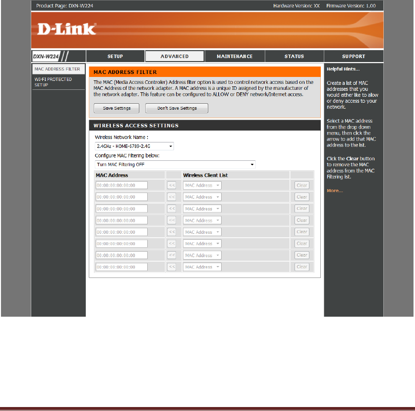
ADVANCED-MAC Filter
Use MAC (Media Access Control) Filters to allow or deny LAN (Local Area Network)
computers by their MAC addresses from accessing the network. You can either
manually add a MAC address or select the MAC address from the list of clients that
are currently connected to the Broadband Router.
Configure MAC Filtering: Select Turn MAC Filtering Off, Allow MAC addresses listed
below, or Deny MAC addresses listed below from the drop-down menu.
MAC Address: Enter the MAC address you would like to filter.
DHCP Client: Select a DHCP client from the drop-down menu and click << to copy
that MAC Address.
Clear: Click to remove the MAC address.
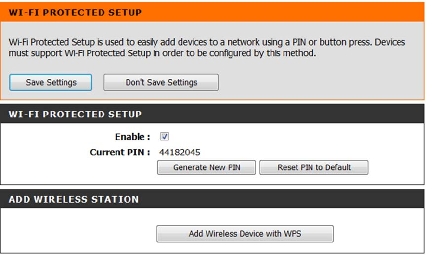
ADVANCED-Wi-Fi Protected Setup
Wi-Fi Protected Setup (WPS) System is a simplified method for securing your wireless
network during the “Initial setup” as well as the “Add New Device” processes. The
Wi-Fi Alliance (WFA) has certified it across different products as well as manufactures.
The process is just as easy, as depressing a button for the Push-Button Method or
correctly entering the 8-digit code for the Pin-Code Method. The time reduction in
setup and ease of use are quite beneficial, while the highest wireless Security setting
of WPA2 is automatically used.
ENABLE: Check this box to enable WPS service.
Current PIN: Shows the current value of the router’s PIN.
A PIN is a unique number that can be used to add the router to an existing network or to
create a new network. The default PIN may be printed on the bottom of the router. For
extra security, a new PIN can be generated. You can restore the default PIN at any time.
Only the Administrator (“admin” account) can change or reset the PIN.
Generate New PIN: Create a random number that is a valid PIN. This becomes the
router’s PIN. You can then copy this PIN to the user interface of the registrar.
Reset PIN To Default: Restore the default PIN of the router.
Add Wireless Station: This Wizard helps you add wireless devices to the wireless
network.
The wizard will either display the wireless network settings to guide you through
manual configuration, prompt you to enter the PIN for the device, or ask you to
press the configuration button on the device. If the device supports Wi-Fi Protected
Setup and has a configuration button, you can add it to the network by pressing the
configuration button on the device and then the on the router within 60 seconds.
The status LED on the router will flash three times if the device has been successfully
added to the network.
There are several ways to add a wireless device to your network. A “registrar” controls
access to the wireless network. A registrar only allows devices onto the wireless network
if you have entered the PIN, or pressed a special Wi-Fi Protected Setup button on the
device. The router acts as a registrar for the network, although other devices may act as
a registrar as well.
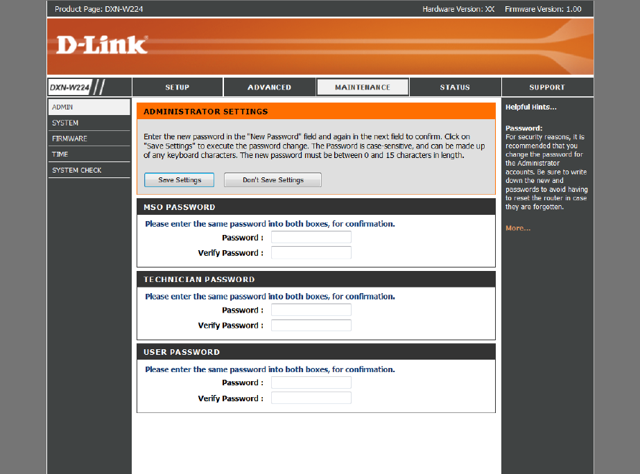
MAINTENACE-ADMIN
This section is to provide the MSO able to configure different access levels for different
users. ADMIN can set the password for three different levels.
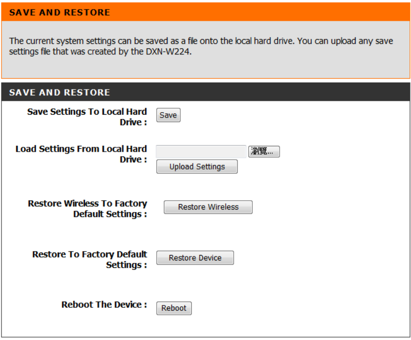
MAINTENACE- SYSTEM
Save settings to local hard drive: Use this option to save the current router
configuration settings to a file on the hard disk of the computer you are using. First,
click the Save button. A file dialog will appear, allowing you to select a location and
file name for the settings.
Local settings from local hard drive: Use this option to load previously saved router
configuration settings. First, use the Browse option to find a previously saved file of
configuration settings. Then, click the Load button to transfer those settings to the
router.
Restore the (wireless) to factory default settings: This option will restore wireless or
all configuration settings back to the settings that were in effect at the time the
router was shipped from the factory. Any settings that have not been saved will be
lost, including any rules that you have created. If you want to save the current router
configuration settings, use the Save button above.
Reboot the device: Click to reboot the router.
MAINTENACE-FIRMWARE
You can upgrade the firmware of the access point here. Make sure the firmware you
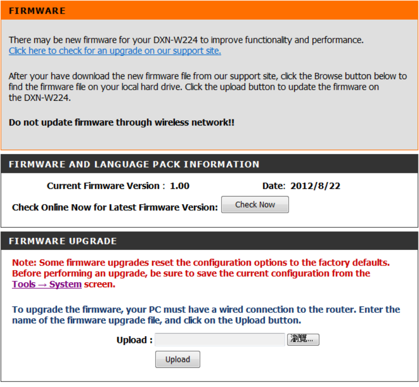
want to use is on the local hard drive of the computer. Click on Browse to locate the
firmware file to be used for the update. Please check the D-Link support website for
firmware updates at http://support.dlink.com. You can download firmware upgrades
to your hard drive from this site.
Browse: After you have downloaded the new firmware, click Browse to locate the
firmware
Upload: After you have downloaded the new firmware, click Browse to locate the
firmware update on your hard drive. Click Upload to complete the firmware
upgrade.
Once you have a firmware update on your computer, use this option to browse for
the file and then upload the information into the access point.
MAINTENCE-TIME
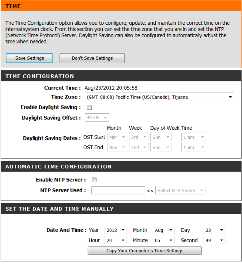
Current Time: Displays the current date and time of the router.
Time Zone: Select your Time Zone from the drop-down menu.
Enable Daylight saving: To select Daylight Saving time manually, select enabled or
disabled, and enter a start date and an end date for daylight saving time.
Enable NTP server: NTP is short for Network Time Protocol. A NTP server will sync
the time and date with your router. This will only connect to a server on the Internet,
not a local server. Check the box to enable this feature.
NTP server used: Enter the IP address of a NTP server or select one from the
drop-down menu.
Set the day and time manually: To manually input the time, enter the values in
these fields for the Year, Month, Day, Hour, Minute, and Second and then click Set
Time.
You can also click Copy Your Computer’s Time Settings to synch the date and time
with the computer you are currently on.
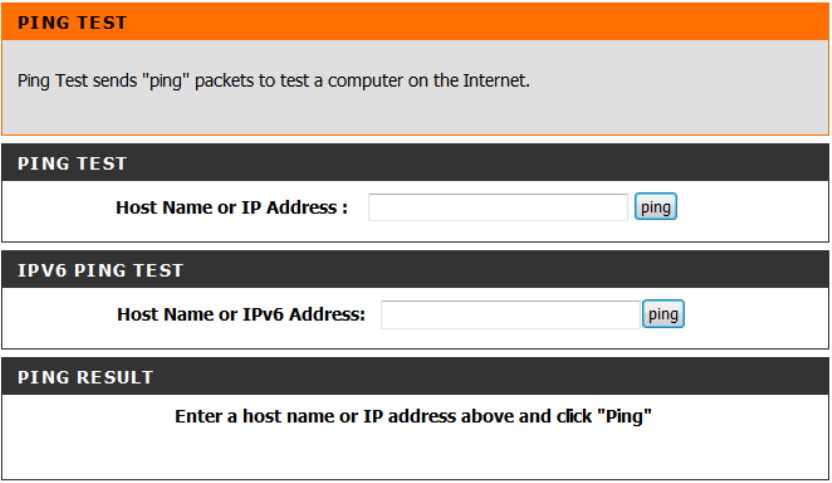
MAINTENACE-System check
The Ping Test is used to send Ping packets to test if a computer is on the Internet.
Enter the IP address that you wish to Ping and click Ping.
Enter the IPv6 address that you wish to Ping and click Ping.
The results of your ping attempts will be displayed here.
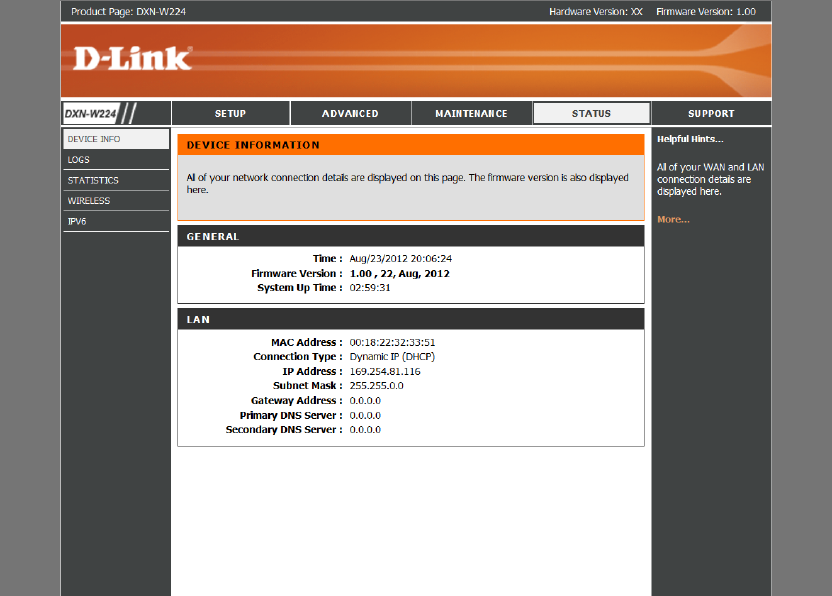
STATUS- Device info
This page displays the current information for the DXN-W224.
General info: Displays the router’s time and firmware version.
LAN Displays the MAC address and the public IP settings.
Displays the MAC address and the private (local) IP settings for the router.
Displays computers and devices that are connected to the router via Ethernet and
that are receiving an IP address assigned by the router (DHCP).
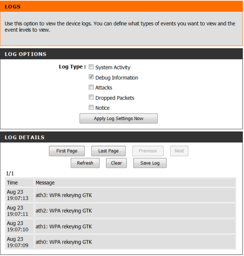
STATUS- LOGS
The router automatically logs (records) events of possible interest in it’s internal
memory. If there isn’t enough internal memory for all events, logs of older events are
deleted but logs of the latest events are retained. The Logs option allows you to view
the router logs. You can define what types of events you want to view and the level
of the events to view. This router also has external Syslog Server support so you can
send the log files to a computer on your network that is running a Syslog utility.
Log Type:You can select the types of messages that you want to display from the log.
System Activity, Debug Information, Attacks, Dropped Packets, and Notice messages
can be selected. Click Apply Log Settings Now to activate your settings.
Refresh: Updates the log details on the screen so it displays any recent activity.
Clear: Clears all of the log contents.
Save Log: This option will send a copy of the router log to your email address
configured in the Tools > Email Settings screen.
This option will save the router log to a file on your computer.
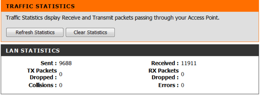
STATUS-Statistics
The screen below displays the Traffic Statistics. Here you can view the amount of
packets that pass through the DXN-W224 on both the WAN, LAN ports.
STATUS-Wireless
The wireless client table displays a list of current connected wireless clients and the
MAC address of the clients.
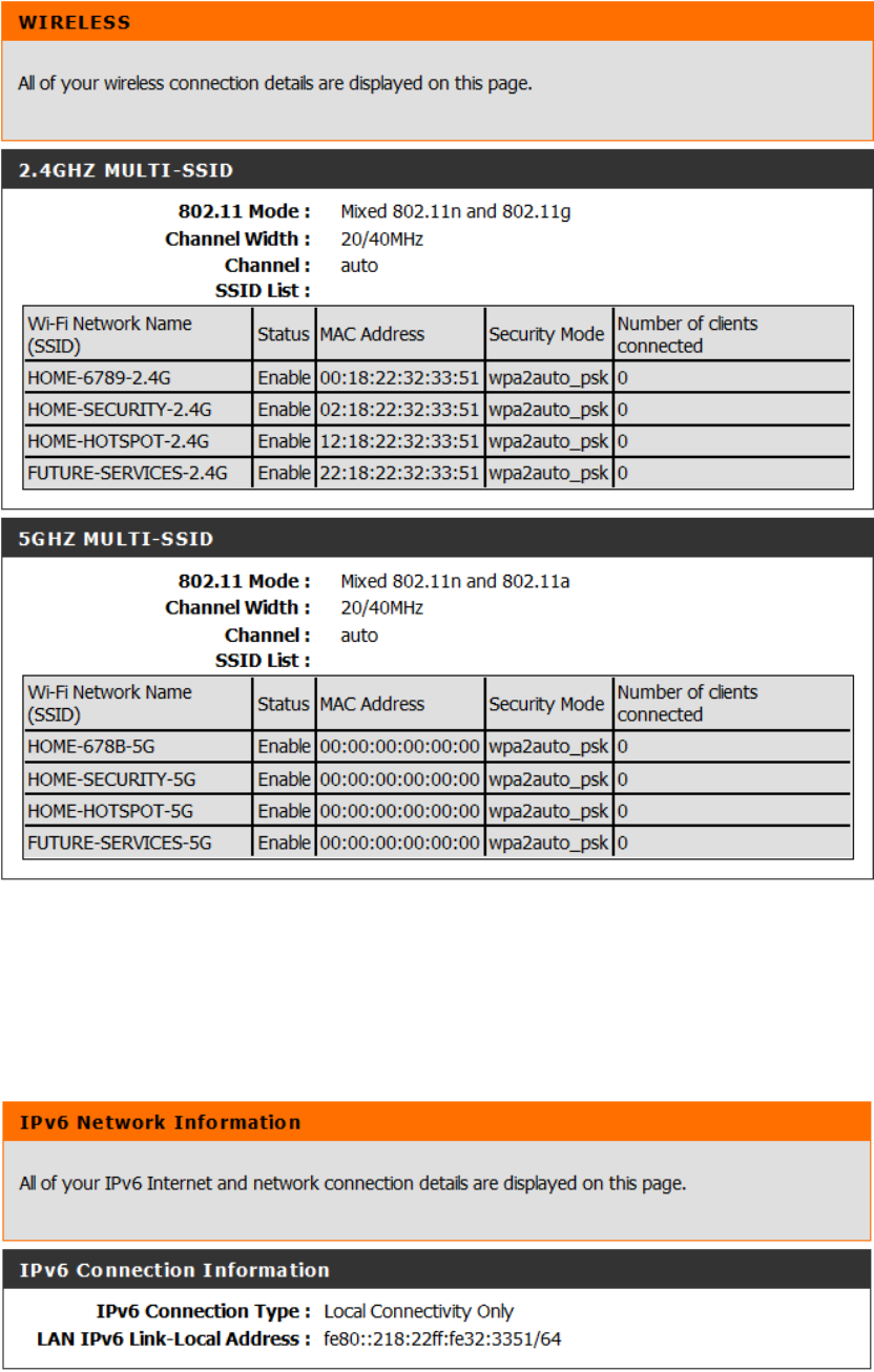
STATUS- IPv6
The IPv6 page displays a summary of the Router’s IPv6 settings and lists the IPv6
address and host name of any IPv6 clients.
Federal Communication Commission Interference Statement
This equipment has been tested and found to comply with the limits for a Class
B digital device, pursuant to Part 15 of the FCC Rules. These limits are
designed to provide reasonable protection against harmful interference in a
residential installation. This equipment generates, uses and can radiate radio
frequency energy and, if not installed and used in accordance with the
instructions, may cause harmful interference to radio communications.
However, there is no guarantee that interference will not occur in a particular
installation. If this equipment does cause harmful interference to radio or
television reception, which can be determined by turning the equipment off and
on, the user is encouraged to try to correct the interference by one of the
following measures:
- Reorient or relocate the receiving antenna.
- Increase the separation between the equipment and receiver.
- Connect the equipment into an outlet on a circuit different from that
to which the receiver is connected.
- Consult the dealer or an experienced radio/TV technician for help.
FCC Caution: Any changes or modifications not expressly approved by the
party responsible for compliance could void the user's authority to operate this
equipment.
This device complies with Part 15 of the FCC Rules. Operation is subject to the
following two conditions: (1) This device may not cause harmful interference,
and (2) this device must accept any interference received, including
interference that may cause undesired operation.
This transmitter must not be co-located or operating in conjunction with any
other antenna or transmitter.
Operations in the 5.15-5.25GHz band are restricted to indoor usage only.
IMPORTANT NOTE:
FCC Radiation Exposure Statement:
This equipment complies with FCC radiation exposure limits set forth for an
uncontrolled environment. This equipment should be installed and operated
with minimum distance 20cm between the radiator & your body.