D and T FS-L4201C 42" Color TFT LCD Monitor User Manual FCC Test Report FS 4201C
D&T; Inc. 42" Color TFT LCD Monitor FCC Test Report FS 4201C
D and T >
User Manual
Printed in Korea
Part No. 942667020001 - 01
TFT-LCD Color Monitor
FS-L4201C
User Manual
English
www.tandberg.net
Parts 3
Connection to Signal Source 4
Out Drawing of product 6
Name and Function 7
Power Management Feature 8
Adjusting OSD 10
Standard Signal Table 12
Pin assignment table of signal connector 13
Specification 15
Troubleshooting 16
Warning 18
INFORMATION TO USER :
This equipment has been tested and found to comply with the limits of a
Class B digital device, pursuant to Part 15 of the FCC Rules.
These limits are designed to provide reasonable protection against harmful
interference in a residential installation.This equipment generates, uses and
can radiate radio frequency energy and,if not installed and used in accor-
dance with the instructions, may cause harmful interference to radio commu-
nications.
However, there is no guarantee that interference will not occur in a particular
installation; if this equipment does cause harmful interference to radio or
television reception, which can be determined by turning the equipment off
and on, the user is encouraged to try to crrent the interference by one or more
of the fllowing measures:
1. Reorient/Relocate the receiving antenna.
2. Increase the separation between the equipment and receiver.
3. Connect the equipment into an outlet on a circuit difference
from that to which the recerver is connected.
4. Consult the dealer or an experienced radio/TV technician for help.
CAUTION
Changes or modifications not expressly approved by the
manufacturer responsible for compliance could void the user's
authority to operate the equipment
Table of Contents
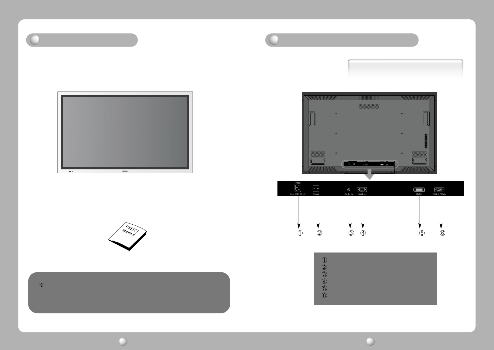
Basic Connection
AC Inlet.
AC on/ off Switch
RCA Coaxial S/PDIF Audio input
9 Pin D-Sub connector for Speaker Out
24 Pin DVI Connector for Digital TMDS
15 Pin D-Sub connector for Analog RGB
User's Manual
42 " LCD Monitor
Parts
Connection to Signal Source
LCD MONITOR User s Manual
3LCD MONITOR User s Manual
4
This monitor do not provide any other accessaries and
peripheral devices (ex,speaker and signal cable) because
the Tandberg's reguest.
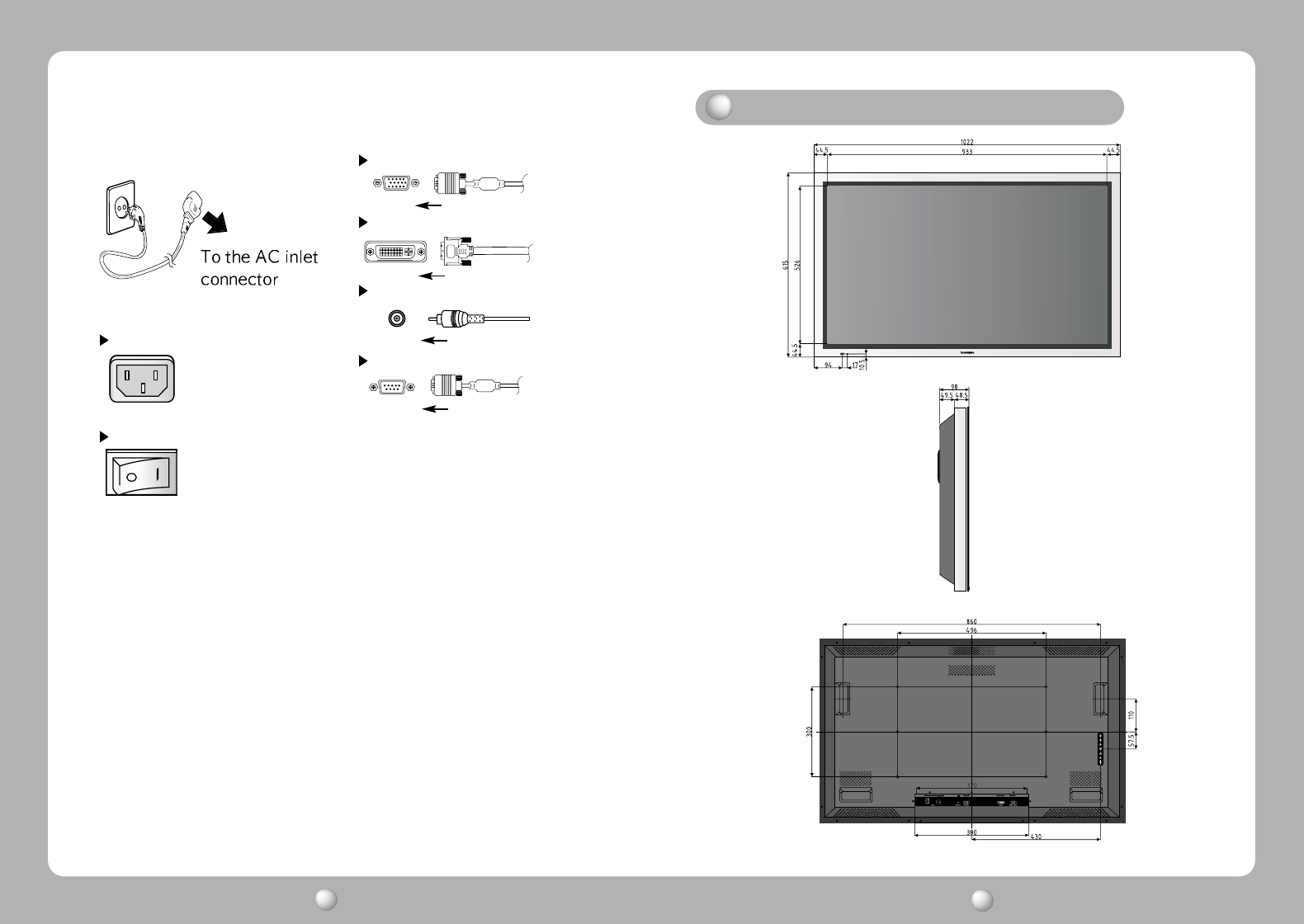
1. Use 220 V or 110 V. (Free Voltage)
2. Connect monitor and Signal Source via Signal cable
3. Power on the monitor and computer.
4. Connection is finished.
D-Sub Analog(Data in)
DVI Digital
< Power source connection > < Signal cable connection>
Coaxial S/PDIF Input
Audio amp Output
O ut Drawing of product
LCD MONITOR User s Manual
5LCD MONITOR User s Manual
6
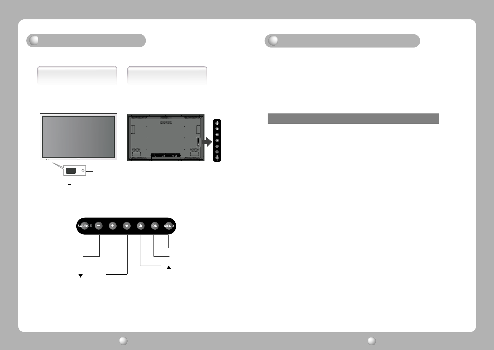
AC Inlet
AC on/off swith
LCD MONITOR User s Manual
7LCD MONITOR User s Manual
8
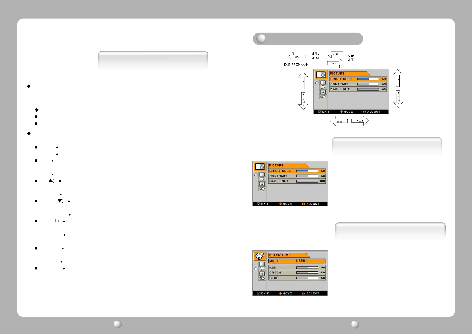
Front side
+
BUTTON
-
BUTTON
SOURCE BUTTON
MENU
BUTTON
OK BUTTON
BUTTON
BUTTON
Name and Function
Rear side
R
emote signal window
P
ower indicating LED
Power Management Feature
Power management system of this monitor can not be corresponded
with VESA DPMS when the display video signal is none because the
specific character of Tandberg system
Status LED Sign Power Consumption
Normal mode Green on Normal Power
Stand by mode Red on 20W or Below
English - 109 - English LCD MONITOR User s Manual
9LCD MONITOR User s Manual
10
Remote signal wirdow
This window is for the receiving signal from remote controller
Do not hide this window.
Power Indicating LED
Green : Normal mode
RED : Standby mode
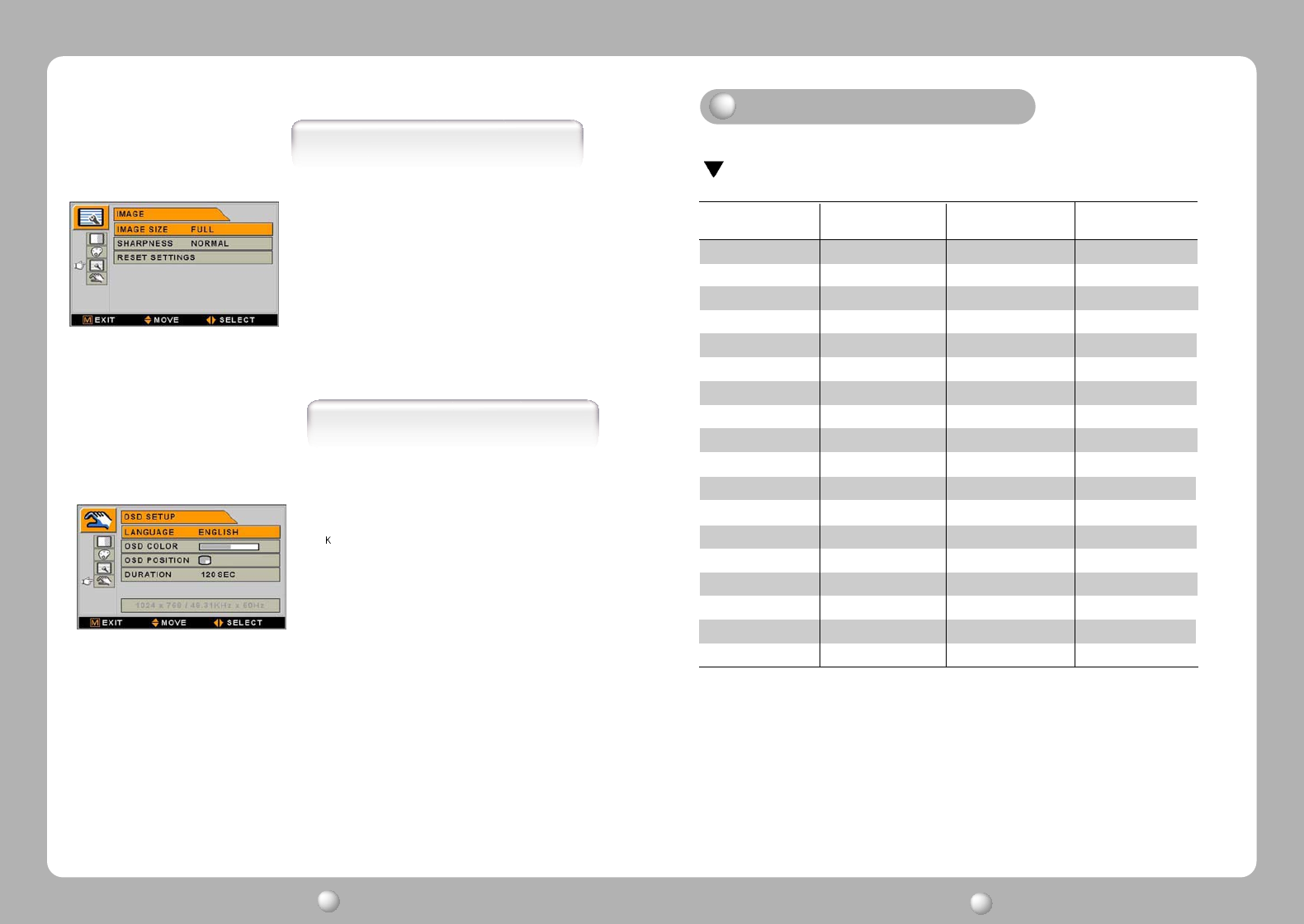
On-Screen Display (OSD) Function Button
MENU
:
With OSD deactivated, Activated to OSD menu
With OSD activated, Exit from main menu or sub menu.
OK : With OSD deactivated, you can see the kind of displayed source on the right
bottom side of the screen.
With OSD activated, Enter sub menu and change each sub menu item
UP( :With OSD deactivated, Hot key of the brightness control and increases
the brightness.
With OSD activated, move the cursor upward.
DOWN( :With OSD deactivated, Hot key of the brightness control and
decreases the brightness.
With OSD activated, move the cursor downward.
PLUS( :With OSD deactivated, Hot key of the contrast control and increases
the contrast.
With OSD activated, enter sub menu and increases the adjustment of
the selected function.
MINUS
(-) : With OSD deactivated, Hot key of the contrast control and decreases
the contrast.
With OSD activated, decreases the adjustment of the selected function.
SOURCE : For the extra function, normally no need to use this button.
Functions
COLOR TEMP
1. MODE
C
hange the Color mode
( 6500, 7200, 9300, USER )
2. RED
R
ed balance
(O
nly Working with
USER
mode
) (R
ange
: 0~100)
3. GREEN
G
reen balance
(O
nly Working with
USER
mode
) (R
ange
: 0~100)
4. BLUE
B
lue balance
(O
nly Working with
USER
mode
) (R
ange
: 0~100)
Adjusting OSD
PICTURE
1. BRIGHTNESS
I
ncrease or decrease the brightness
(R
ange
: 0~100)
2. CONTRAST
I
ncrease or decrease the Contrast
(R
ange
: 0~100)
3. BACK LIGHT
I
ncrease or decrease the
CCFL
back light luminance
(R
ange
: 0~100)
LCD MONITOR User s Manual
11 LCD MONITOR User s Manual
12
(640 X 480)
(640 X 480)
(640 X 480)
(640 X 480)
(800 X 600)
(800 X 600)
(800 X 600)
(800 X 600)
(800 X 600)
(800 X 600)
(1024 X 768)
(1024 X 768)
(1024 X 768)
(1280 X 768)
(1280 X 720)
(1280 X 720)
(1280 X 1024)
(1366 X768)
31.5
37.9
37.5
43.3
31.5
35.1
37.9
48.1
46.9
53.7
48.4
56.5
60
47.7
37.5
45
64
48.32
60
72
75
85
50
56
60
72
75
85
60
70
75
60
50
60
60
60
25.175
31.5
31.5
36
35.4375
36
40
50
49.5
56.25
65
75
78.75
79.5
74.25
74.25
108
87.75
Resolution
Horizontal Frequency
(KHz)
Vertical Frequency
(Hz) Clock Frequency
(MHz)
PC Supported Mode
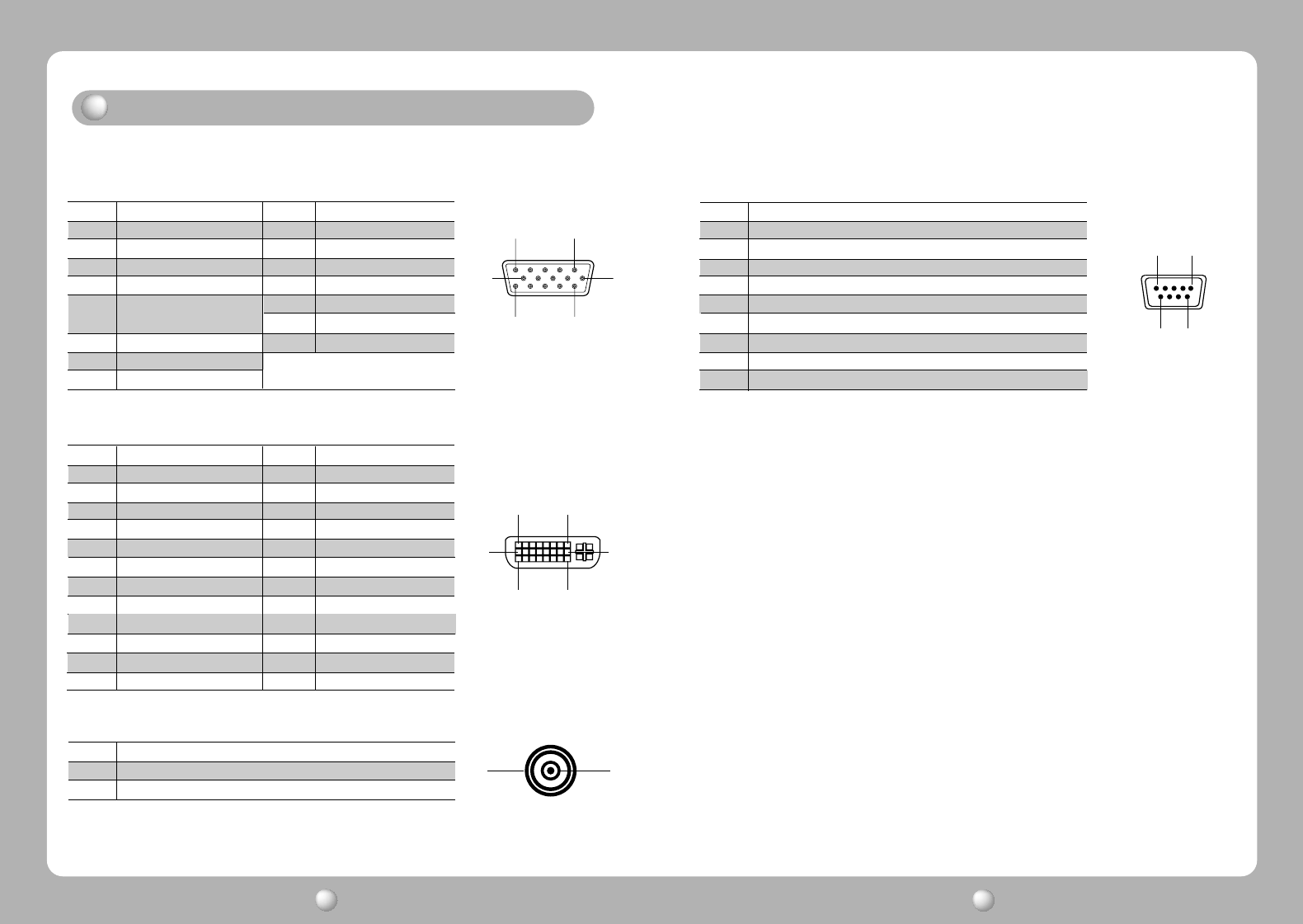
SETUP
1. IMAGE SIZE
C
hange the image size (Scaling mode)
(F
ull,Fill aspect, 1:1)
2. SHARPNESS
S
et the sharpness of image
(S
oftest,Softest,Normal,Sharp,Sharpest
)
3. RESET SETTINGS
C
hanges all OSD values to factory outgoing status.
IMAGE
1. LANGUAGE
C
hange the OSD language
orean
,E
nglish,French,Spanish,German,Chinese,Japanese,Italian
2. OSD COLOR
A
djust the OSD back ground from white opaque to half translucent.
3. OSD POSITION
C
hange the OSD position (9 postions)
4. DURATION
A
djust OSD display time
(5, 10, 20, 30, 60, 90, 120, 180, 240
seconds
)
Standard Signal Table
LCD MONITOR User s Manual
13 LCD MONITOR User s Manual
14
15
69
9 Pin D-sub
Pin No. Assignment
1 Ground
2 Speaker ID4
3 Speaker ID3
4 Speaker ID2
5 Speaker ID1
6 Speaker Out Left-
7 Speaker Out Left+
8 Speaker Out Right-
9 Speaker Out Right
15
11 15
610
15pin D-Sub
Pin No. Assignment Pin No. Assignment
1 Red 9 NC
2 Green 10 Ground-Sync
3 Blue 11 Ground
4 Ground 12 DDC Data
5 DDC 5V Standby 13 H.Sync
Cable Connection check 14 V.Sync
6 Ground-Red 15 DDC Clock
7 Ground-Green
8 Ground-Blue
18
17 24
916
24 Pin DVI-D
21
RCA
Pin No. Assignment Pin No. Assignment
1 T.M.D.S. Data2- 13 No Connect
2 T.M.D.S. Data2+ 14 No Connect
3 T.M.D.S. Data2 Shield 15 Cable Connection check
4 No Connect 16 Hot Plug Detect
5 No Connect 17 T.M.D.S. Data0-
6 DDC Clock 18 T.M.D.S. Data0+
7 DDC Data 19 T.M.D.S. Data0 Shield
8 No Connect 20 No Connect
9 T.M.D.S. Data1- 21 No Connect
10 T.M.D.S. Data1+ 22 Cable Connection check
11 T.M.D.S. Data1 Shield 23 T.M.D.S. Clock+
12 No Connect 24 T.M.D.S. Clock-
Pin No. Assignment
1 Coaxial S/PDIF audio signal
2 Ground
Pin assignment table of signal connector
LCD MONITOR User s Manual
15 LCD MONITOR User s Manual
16
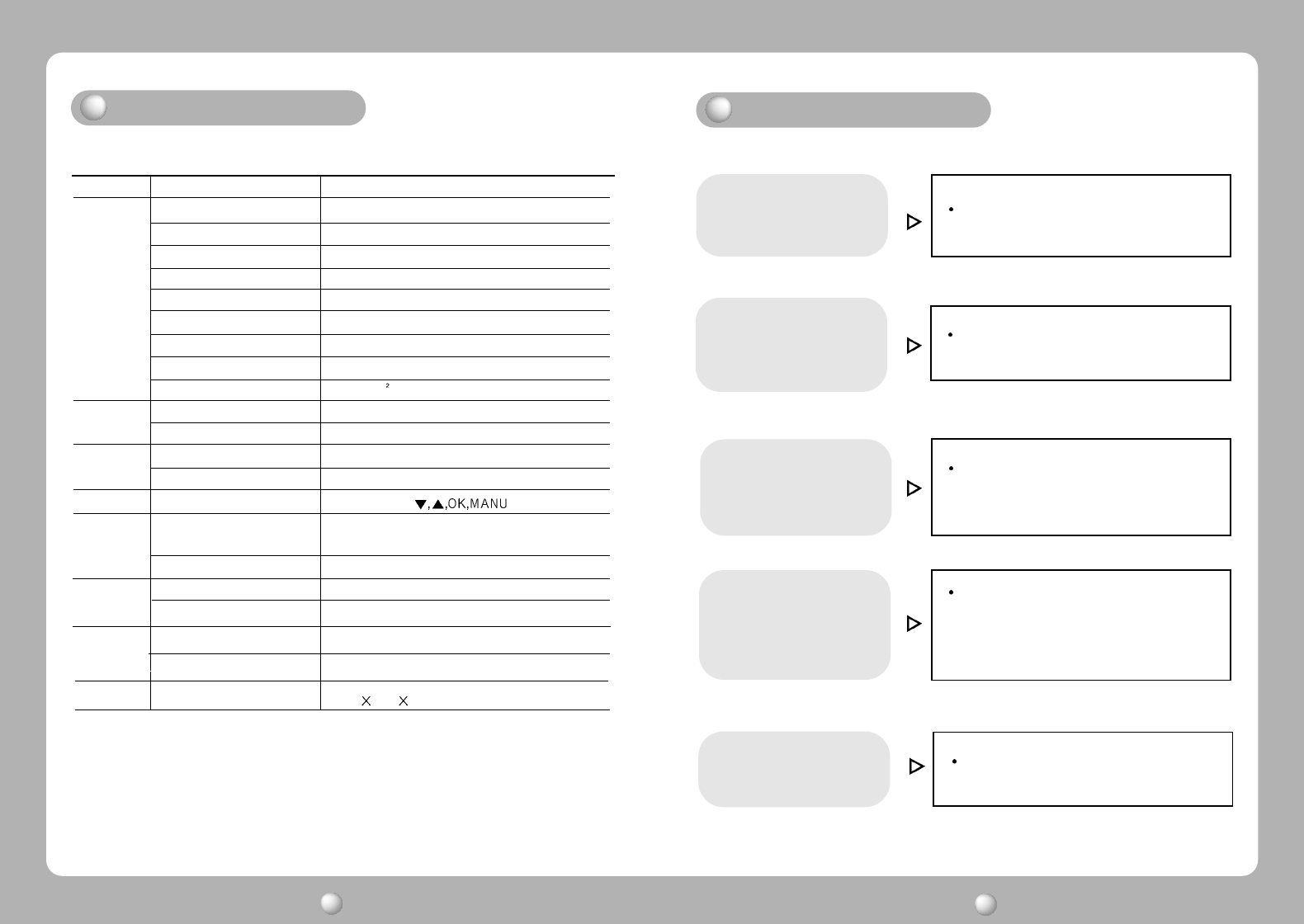
Adjust COLOR at User Mode in OSD Color
Temp Menu.
Color is irregular.
Check the power connection.
(Refer to page 5)
Power LED is dark.
No picture.
Power LED is Red Check the signal cable or signal Source.
(Refer to page 5)
Screen is not clear.
Check the resolution and frequency of
computer and video card, and set up
again.Refer to the current monitor
mode and standard signal mode table.
(Refer to page 12)
Display is unstable and
trembling.
Remove and check attaches to the signal line
(Video extension cable and others)
and switch on.
Troubleshooting
Type a-si TFT Active matrix
Screen Size 106.7cm (Diagonal)
Maximum Resolution
1366 X 768@ 60 Hz
Pixel Range
0.681(H) mm X 0.227(V) mm
Display Colors 16.7M (RGB 8-bit data)
Contrast Ratio 1000 : 1
Viewing Angle 89° / 89° / 89° / 89°
Response Time 10 msec
Luminance 500 cd/m
Horizontal Frequency 91kHz (Max.)
Vertical Frequency 85Hz (Max.)
Maximum 300W
standby Mode Under 20W
SOURCE, -,+,
Video Analog RGB
DVI Digital
Audio S/PDIF (Coaxial)
Video VGA,SVGA,XGA,WXGA
Audio IEC-958 S/PDIF 32kHz,44.1kHz,48kHz,96kHz
Safety Standard UL,C-TICK,EK,CCC
EMI CE,MIC,BSMI,FCC
Size and Weight
1022 615 98 / 29kg
LCD
Panel
Synchro
nization
Model FS-L4201C
Input
Signal
Compati
bility
Power
Consumption
Control key
Rear side
Safety
Standard
& EMI
Dimension
Specification
LCD MONITOR User s Manual
17 LCD MONITOR User s Manual
18
Warning
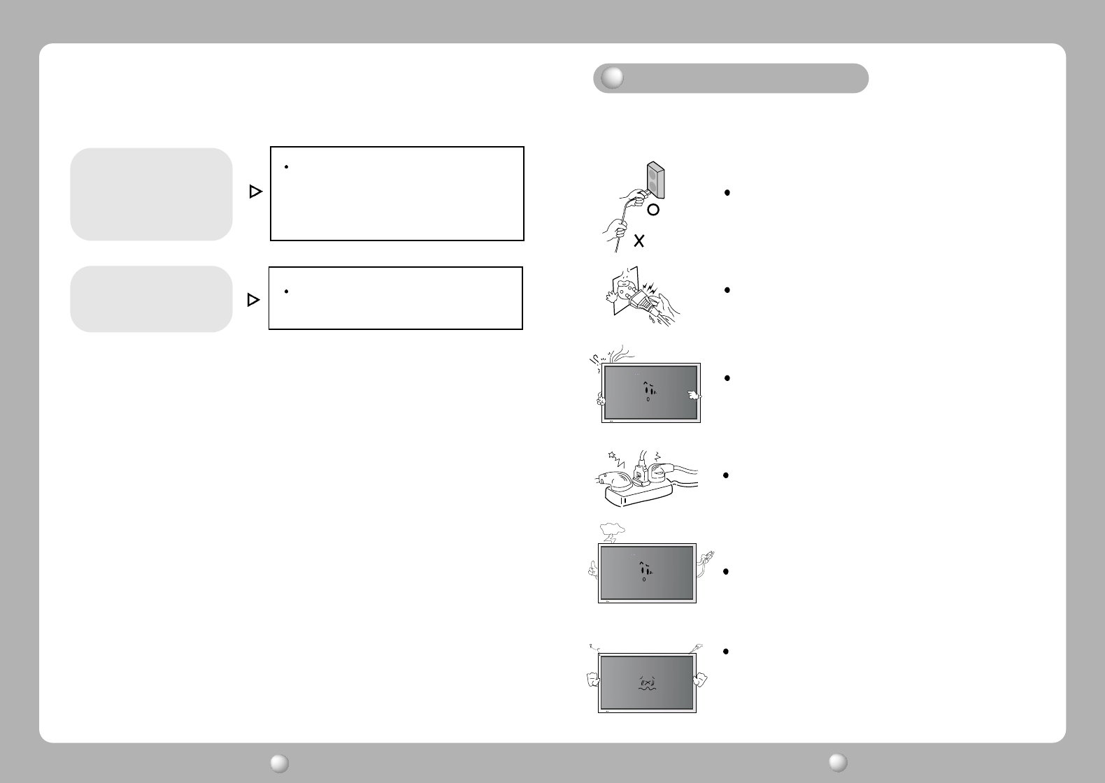
To prevent damage or loss, please read this warning carefully.
When connecting/disconnecting the plug, pull out
the plug itself, and never pull the cord to prevent fire
caused by short.
To prevent electric shock, do not connect/dis-
connect the plug with wet hand.
To prevent fire, do not connect a large number of
equipments in a single line.
To prevent fire and electric shock, pull out the plug in
case of thunder and lightening.
To prevent fire and electric shock, do not try to take
the monitor apart or repair it yourself. Contact your
local service station or customer service center for
inspection, modification or repair.
If you see smoke or smell something burning, stop
using the unit, switch off the power, pull out the plug,
and then contact your local service station.
Check the resolution and frequency of
computer and video card, and set up
again in reference to the current monitor
mode and standard signal mode table.
(Refer to page 5)
Double images or
'ghosts'.
Adjust COLOR at User Mode in OSD Color
Temp Menu.
Picture is dark.

19 - English