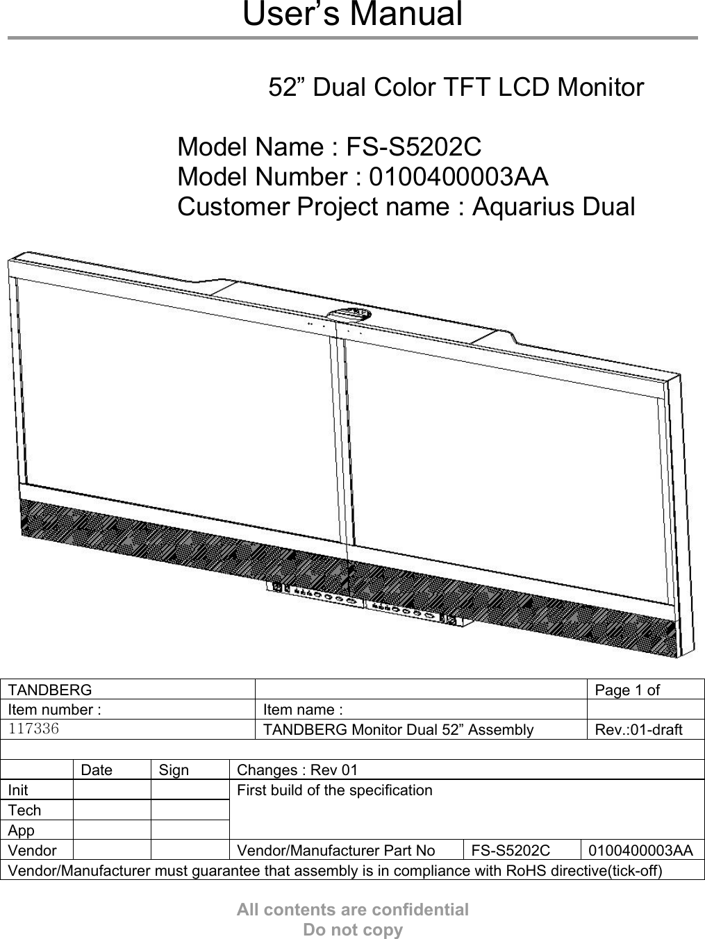
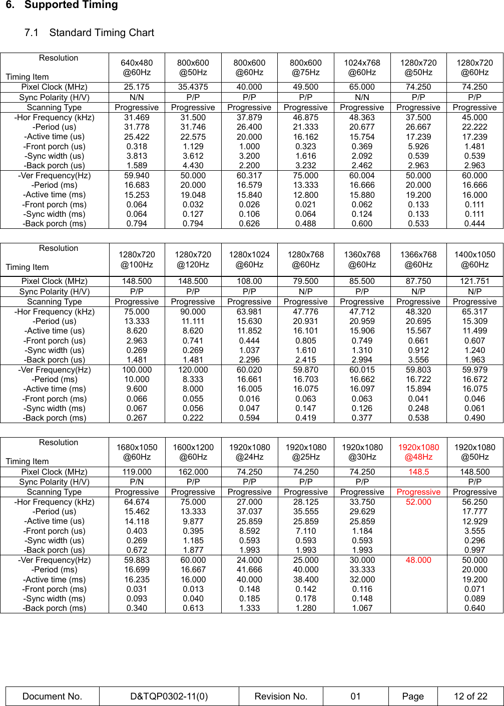
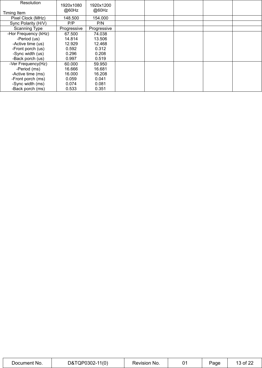
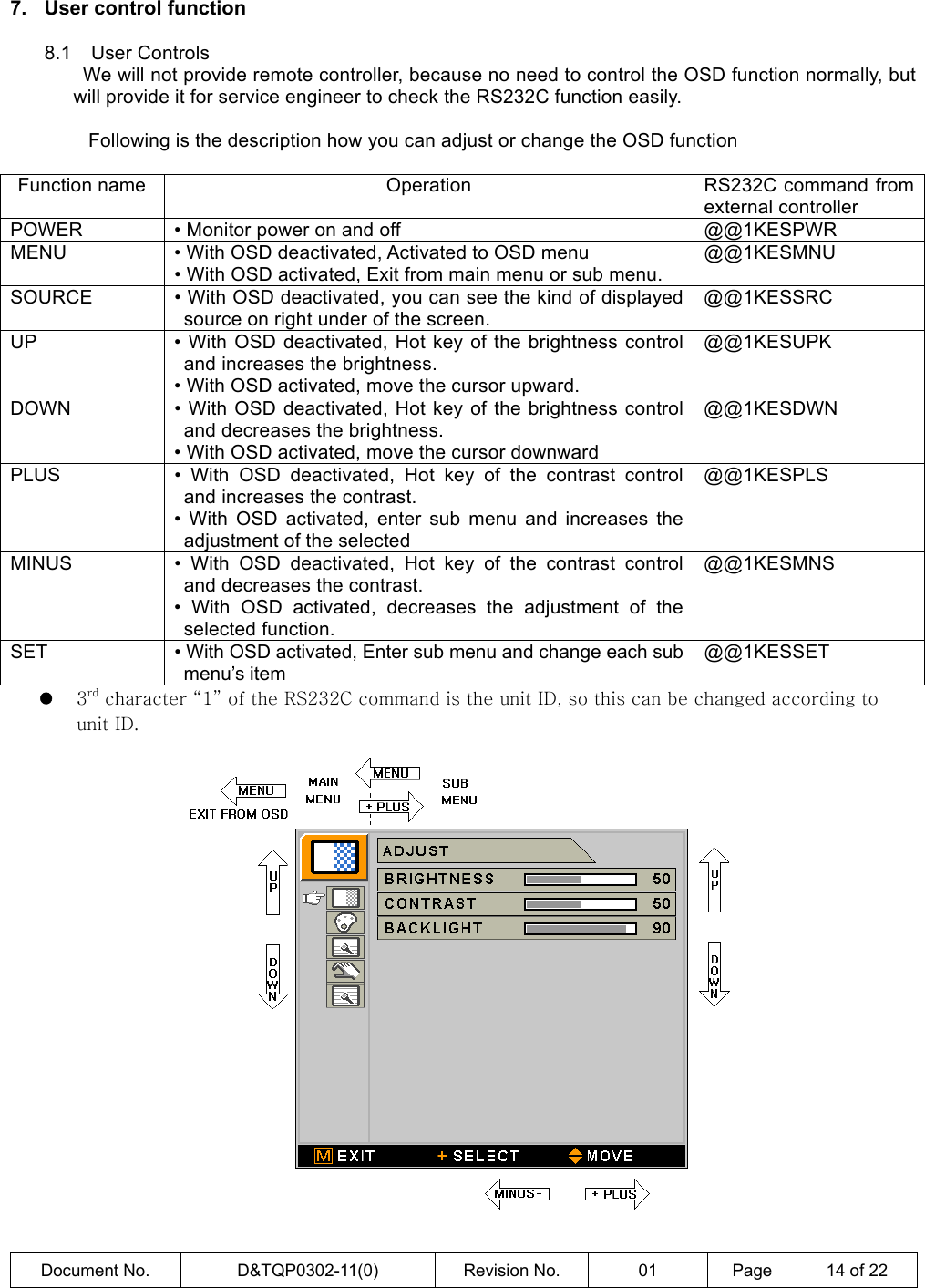
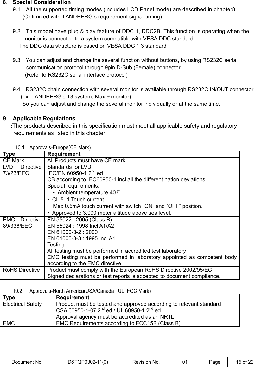
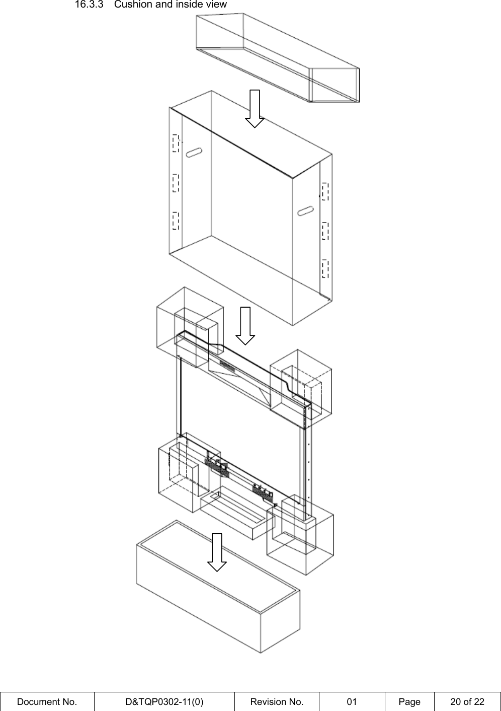
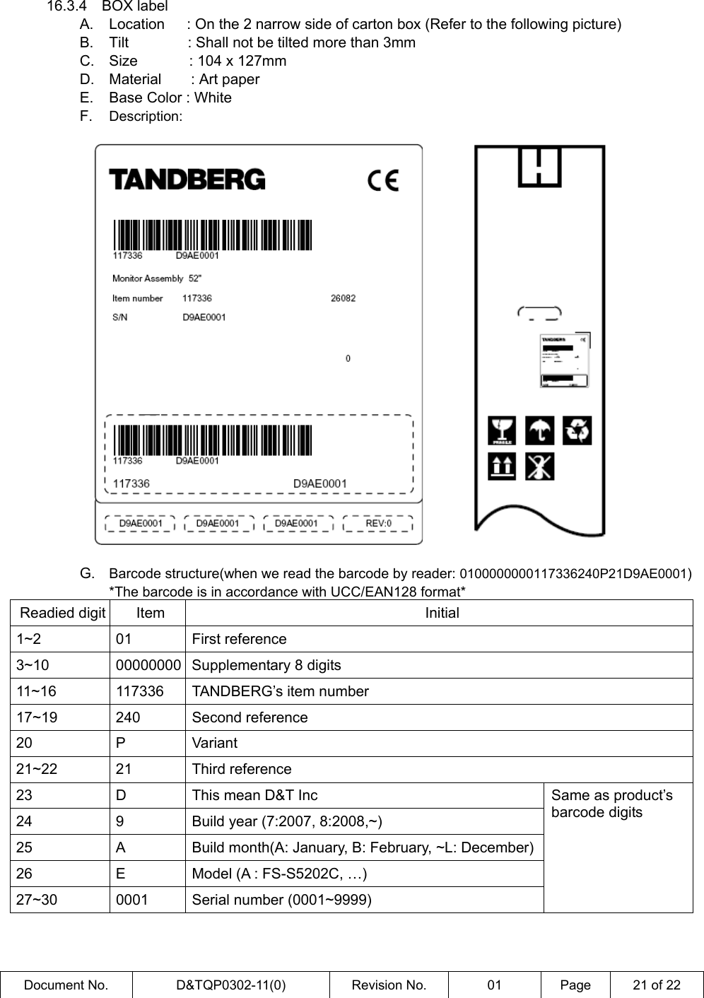
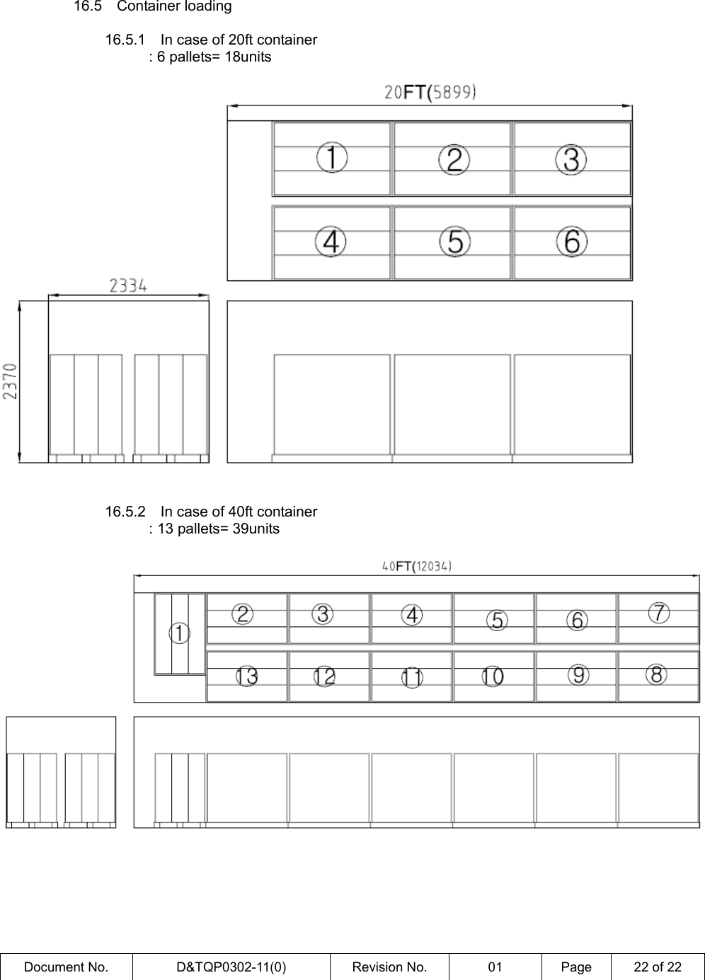
D and T FS-S5202C 52" DUAL COLOR TFT LCD MONITOR User Manual

D&T; Inc. 52" DUAL COLOR TFT LCD MONITOR Users Manual

Users Manual

 User’s Manual   52” Dual Color TFT LCD Monitor  Model Name : FS-S5202C Model Number : 0100400003AA Customer Project name : Aquarius Dual    TANDBERG    Page 1 of   Item number :    Item name :     117336  TANDBERG Monitor Dual 52” Assembly  Rev.:01-draft    Date  Sign  Changes : Rev 01 Init    Tech    App    First build of the specification Vendor   Vendor/Manufacturer Part No FS-S5202C 0100400003AAVendor/Manufacturer must guarantee that assembly is in compliance with RoHS directive(tick-off)  All contents are confidential Do not copy
General Specification INFORMATION TO USER :
 Document No.  D&TQP0302-11(0)  Revision No.  01  Page  2 of 22  1. General Description and Scope   2.1 General Description    This specification applies to the Type 52” Color TFT/LCD Module “LTI520HB01”. This module is designed for a LCD TV style display unit. The screen format and electrical interface are intended to support the VESA WUXGA (1920(H) ×1080(V) at 60Hz) screen. Supported Color is native 16.7M colors (RGB-8bit data driver). All input signals are LVDS (Low Voltage Differential Signaling) interface compatible.    2. Environmental and Reliability Specifications   3.1 Operating Conditions  3.1.1  Temperature  : 0℃~ 40℃ Note : Max. Operating Temperature 40℃  in the spec means the temperature measured at the point of the front surface of the LCD glass cell.   3.1.2    Humidity : 10% ~ 90%, non-condensing       3.1.3  Altitude : maximum 4,500m       3.1.4  Test  Type Parameters  Description and comments  ResultsLow temperature T = 0°C Dwell time = 8h + 2h (power-off) Cold start-up after the power-off period    PassedHigh temperature T = +40°C   Dwell time = 8h + 2h (power-off) Warm start-up after the power-off period   Shield the unit against direct airflow  PassedLow pressure P = 60kPa (4206m) Pressure dwell time = 2h T = +40°C   Shield the unit against direct airflow  Passed 0.5h1h 2h0.5h Lab amb  1h 3.5h 2.5h 0.1h 0.1h 0.5h1h8h0.5h Lab amb  2h 1h 0.5h1h8h0.5h Lab amb  0 2h 1h
 Document No.  D&TQP0302-11(0)  Revision No.  01  Page  3 of 22   3.2  Non-Operational Conditions      3.2.1  Temperature  : -20℃~ 60℃     3.2.2  Humidity        : 10% ~ 90%, non-condensing     3.2.3  Altitude       : maximum 15,000m     3.2.4  Test  Type Parameters  Description and comments  ResultsLow temperature T = -20°C Dwell time  = 16h  PassedHigh temperature T = +60°C   Dwell time = 16h  PassedThermal shock Low temperature = -20°C High temperature = +60°C Temperature gradient = 5°C/min Dwell time = 2h No. of cycles = 3  PassedHumidity RH = 90% Low temperature  = 30°C High temperature  = 60°C No. of cycles: 5 ea 24h    Passed    3h9h3h9h 6030One cycle
 Document No.  D&TQP0302-11(0)  Revision No.  01  Page  4 of 22    3.3  Packing Conditions     3.3.1  Temperature   : -20℃~ 50℃    3.3.2  Humidity        : 10% ~ 90%, non-condensing    3.3.3  Altitude       : maximum15,000m    3.3.4  Test  Type Parameters  Result Drop surface  Concrete or steel Drop height  Weight    > 100kg: 0.1m Impact area  6 faces 1 selected corner 1 selected edge      Freefall Drop No. of drops  1 per impact area Passed Frequency range  5-10Hz  10-50Hz Displacement   3.5mm   Acceleration   1g Sweep rate  3min(5-50-5) vibration Duration  Right/Left : 15min Front/Back : 15min Up/Down : 30min Passed
 Document No.  D&TQP0302-11(0)  Revision No.  01  Page  5 of 22  3. Input Signal and AC Power   4.1  AC Power        4.1.1  AC input voltage     : AC 100 to 240 Volts (Universal power)       4.1.2  AC input frequency   : 50~60Hz ±3Hz   4.2    Video and Sync Signal       4.2.1  Video signal A.  Horizontal frequency : 25 ~ 90KHz B.  Vertical frequency : 24 ~ 120Hz C.  Applicable maximum pixel frequency : 170MHz(Analog), 165MHz(Digital) D.  Maximum resolution : 1920x1200 / 60Hz      4.2.2  Signal connectors A.  HDMI type Ax3x2(Dual) : HDMI input B.  15p D-Sub(Female, 3row) x1x2(Dual) : Analog RGB input C.  9p D-Sub (Female) x1x2(Dual) : RS232C Input D.  9p D-Sub (Male) x1x2(Dual) : RS232C Output E.  15p D-Sub(Male, 2row) x1x(Dual) : Audio AMP signal input F.  AC Inlet x1x2(Dual) : main AC power input  4. Electrical Performance: Except where noted, the following test conditions are required.   5.1  Standard Testing Conditions      5.1.1  AC power voltage and frequency : AC 100 ~ 240V±10%, 60Hz/50Hz±3Hz     5.1.2  Ambient temperature: 25℃± 5℃     5.1.3  Brightness setting : set brightness control to the maximum level of the OSD       5.1.4    LCD panel direction : test at the parallel position with LCD panel center line       5.1.5    Ambient light level : between 300 lux and 700 lux    5.2  Power management      5.2.1  Power management : This system can save energy by switching this monitor into a low-mode when the display video signal is none. But power Management system can not be corresponded with VESA DPMS, because of the TANDBERG’s operation specification.      5.2.1  Power Management Modes. State Power consumption Normal operation  Max 1000Wrms DPMS or Standby mode  Max 50Wrms Sleep mode  Max 3.5Wrms
 Document No.  D&TQP0302-11(0)  Revision No.  01  Page  6 of 22    5.3    LCD (Liquid Crystal Display) Panel Specifications    This specification applies to the Type 52” Color TFT/LCD Module “LTI520HB01”. This module is designed for a LCD TV style display unit. The screen format and electrical interface are intended to support the WUXGA(1920(H) ×1080(V)) screen. Supported gray scales are native 8bit per 1(one) sub pixel. All input signals are LVDS(Low Voltage Differential Signaling) interface compatible.       5.3.1  General specification  Item SPECIFICATION UNIT NOTE diagonal   1321  mm Display area  viewable 1152.0(H) × 648.0(V)  mm  Driver element  a-Si TFT Active matrix     Number of Pixels  1920x1080, 2.07Million  pixels   Pixel Pitch  0.6(H) ×0.6(V)    mm   Pixel arrangement  R. B, G Vertical Stripe     Display colors  16.7M (RGB 8-bit data)     Viewing angle(max)  178(H), 178(V)  degrees  120 minutes after lighting on Display mode  Normally black          5.3.2  Optical characteristics (LCD panel specification)   The following optical characteristics are measured under stable conditions. It takes about 120minutes to reach stable conditions. The measuring point is the center of display area unless otherwise noted.   The optical characteristics should be measured in a dark room or equivalent state. Measuring equipment : TOPCON BM-7, SPECTRORADIOMETER SR-3 Temperature of LCD surface=25℃, VDD=12.0V, fV=60Hz, BRT=High(PWM Duty 100%)  ITEM  SYMBOL  CONDITION Min.  Typ.  Max.  UNIT Contrast Ratio  C/R  1300  1700  -  - Rise  Tr  -  14  24  ms Response Time  Fall  Tf  -  8  10  ms Brightness of white  Bwh  500  600  -  cd/m² x  0.645Red  y  0.336x  0.275Green  y  0.606x  0.143Blue  y  0.067x  0.280Color Chromaticity (CIE) White  y θ=0°  1)  TYP -0.030.290TYP +0.03  - θL  75  89  - Hor  θR  75  89  - θU  75  89  - Viewing Angle  Ver  θD  75  89  - Degree
 Document No.  D&TQP0302-11(0)  Revision No.  01  Page  7 of 22   Normal Lineθ Lθ Rφ Hφ LθR =90oθ L =90oφ = 0o, xx*y*yθ = 0oφ H = 90o φL = 90o    Definition of Response time : Display data  White(TFT ON)Black(TFT OFF) Black(TFT OFF)Opti calResponse100%  90% 10%   0%TRTFTime      5.3.3  Luminance Uniformity   When the backlight is on with all pixels in the white (maximum gray) level, the luminance   uniformity is defined as follow;   Where;  Lbright : The luminance of the brightest part of the area  Ldark    :The luminance of the darkest part of the area   Adjacent Area   Luminance Uniformity = ( Lbright - Ldark ) / Lbright ≤ 0.25   Over a circular area of 10mm diameter placed anywhere on the screen   Screen Total   Luminance Uniformity = ( Lbright - Ldark ) / Lbright ≤ 0.25   Over the entire screen    5.4    Front of screen (FOS) performance       5.4.1    Chromaticity(White) : X = 0.280, Y = 0.290       5.4.2    Luminance : no less than 500㏅/㎡   Controls setting condition : contrast and brightness max
 Document No.  D&TQP0302-11(0)  Revision No.  01  Page  8 of 22      5.4.3  Minimum luminance : less than 30cd/㎡  with full white pattern at the contrast default and             minimum brightness and minimum back light level       5.4.4    Gray scale linearity : The 16 step gray bars shall be distinguishable at the default contrast and             default brightness or 3 steps down contrast setting of the OSD menu       5.4.5    Noise : Pixel displacement, jitter, or swim shall not be visible to the eye when viewed at 50cm              from the LCD panel surface.    5.5  Defect      : Defects are considered to be impairments to video quality, which exist independently of       displayed information. They may be electrical, mechanical, or physical imperfection of       display resulting from processing, handling, shipping, etc.      5.5.1  Bright and Black Dots   The following Table describes the specification of bright and black dots in the visual  screen quality of the TFT-LCD module at power-ON.                              5.5.2  Visual Screen Quality Item Size(mm) Permissible  Number Operation Condition Circular 0.3∠D≤3.0  5  with white picture Foreign Material (in the polarizer, Cell)  Linear  2∠L≤15.0  5  with white or black picture Bright Foreign Material (in polarizer or cell) 0.3≤D≤0.5  5  with black picture Scratches on the polarizer / glass  2∠L≤15.0  5 Dent on the polarizer / glass  0.3≤D≤0.8  10 Non operation z D: Average Diameter, L: Length,       Items Specification Any Bright Dots(Two joined dot must be counted 2) Any Black Dots(Two joined dot must be counted 2) Bright and Black Dots(total) Two Joined Bright Dots Three Joined Bright Dots. Two joined Black Dots Three Joined Black Dots Minimum distance between dot defects    Bright dot – Bright dot       Black dot – Black dot 5x2 Max 10x2 Max 15x2 Max 1x2 Max 1x2 Max 2x2 Max 1x2 Max  5mm Ignore Basic Conditions: Viewing Distance             1500±10 mm Ambient Illumination          300~700 lux(Normal 500lux) Ambient Temperature         25±5  ℃
 Document No.  D&TQP0302-11(0)  Revision No.  01  Page  9 of 22  5.  Signal Connections and Pin Assignments     6.1  AC Inlet socket  Pin Signal Assignment 1 Live 2 Neutral 3 GND    6.2  HDMI Connector (Type A)    Pin  Signal Assignment  Pin  Signal Assignment 1  TMDS Data2+  2 TMDS Data2 Shield 3  TMDS Data2-  4 TMDS Data1+ 5  TMDS Data1 Shield  6 TMDS Data1- 7  TMDS Data0+  8 TMDS Data0 Shield 9  TMDS Data0-  10 TMDS Clock+ 11  TMDS Clock Shield  12 TMDS Clock- 13  NC  14 NC 15  DDC SCL  16 DDC SDA 17  DDC Ground  18 +5V Power 19  Hot Plug Detect
 Document No.  D&TQP0302-11(0)  Revision No.  01  Page  10 of 22    6.3    15pin D-Sub Connector : Analog RGB signal input    Pin  Signal Assignment  Pin  Signal Assignment 1 Red  9  NC 2 Green  10  GND-Sync 3 Blue  11  GND 4 GND  12  DDC SDA 5  DDC 5V Standby /Cable connection check  13 H Sync 6 GND-Red  14  V Sync 7 GND-Green  15  DDC SCL 8 GND-Blue        6.4    9pin D-Sub(Female) Connector : RS232C Input   Pin  Signal Assignment  Pin Signal Assignment 1 RS232 ID  6 NC 2 RS232 RXD  7 NC 3  RS232 TXD  8  +5V Output 4 NC  9 NC 5 GND        6.5    9pin D-Sub(Male) Connector : RS232C Output z This connector is used for chain connection with other Eagle monitor.
 Document No.  D&TQP0302-11(0)  Revision No.  01  Page  11 of 22   Pin  Signal Assignment  Pin Signal Assignment 1 NC  6 NC 2 RS232 RXD  7 NC 3 RS232 TXD  8 NC 4 NC  9 NC 5 GND        6.6  15pin D-Sub(Male, 2row) Connector    Pin  Signal Assignment  Pin  Signal Assignment 1  Speaker ID 1    9  Left Full Range + 2  Speaker ID 0  10  Left Full Range - 3  Center Tweeter +  11  Right Full Range + 4  Center Tweeter -  12  Right Full Range - 5  Center woofer1 +  13  LMNT 6  Center woofer1 -  14  AMP Ground 7  Center woofer2 +  15  Speaker ID 2 8  Center woofer2 -     z This connection is optimized for TANDBERG’s DNAM AMP system, And DNAM Identify the speaker ID so that output appropriate audio signal to match this monitor’s speaker module.* z On this monitor the pin1(Speaker ID 1) must be connected to ground by using internal speaker wiring. Pin name  LMNT  Speaker ID 2  Speaker ID 1  Speaker ID 0 Set digit to 1 1 0 1 1 : must be floated 0 : must be tied to circuit ground
 Document No.  D&TQP0302-11(0)  Revision No.  01  Page  12 of 22  6. Supported Timing  7.1  Standard Timing Chart  Resolution  Timing Item 640x480 @60Hz 800x600 @50Hz 800x600 @60Hz 800x600 @75Hz 1024x768 @60Hz 1280x720 @50Hz 1280x720 @60Hz Pixel Clock (MHz)  25.175  35.4375  40.000  49.500  65.000  74.250  74.250 Sync Polarity (H/V) N/N P/P P/P P/P N/N P/P P/P Scanning Type  Progressive  Progressive Progressive Progressive Progressive Progressive Progressive-Hor Frequency (kHz) -Period (us) -Active time (us) -Front porch (us) -Sync width (us) -Back porch (us) 31.469 31.778 25.422 0.318 3.813 1.589 31.500 31.746 22.575 1.129 3.612 4.430 37.879 26.400 20.000 1.000 3.200 2.200 46.875 21.333 16.162 0.323 1.616 3.232 48.363 20.677 15.754 0.369 2.092 2.462 37.500 26.667 17.239 5.926 0.539 2.963 45.000 22.222 17.239 1.481 0.539 2.963 -Ver Frequency(Hz) -Period (ms) -Active time (ms) -Front porch (ms) -Sync width (ms) -Back porch (ms) 59.940 16.683 15.253 0.064 0.064 0.794 50.000 20.000 19.048 0.032 0.127 0.794 60.317 16.579 15.840 0.026 0.106 0.626 75.000 13.333 12.800 0.021 0.064 0.488 60.004 16.666 15.880 0.062 0.124 0.600 50.000 20.000 19.200 0.133 0.133 0.533 60.000 16.666 16.000 0.111 0.111 0.444  Resolution  Timing Item 1280x720 @100Hz 1280x720 @120Hz 1280x1024@60Hz 1280x768 @60Hz 1360x768 @60Hz 1366x768 @60Hz 1400x1050@60Hz Pixel Clock (MHz)  148.500  148.500  108.00  79.500  85.500  87.750  121.751 Sync Polarity (H/V)  P/P  P/P  P/P  N/P  P/P  N/P  N/P Scanning Type  Progressive  Progressive Progressive Progressive Progressive Progressive Progressive-Hor Frequency (kHz) -Period (us) -Active time (us) -Front porch (us) -Sync width (us) -Back porch (us) 75.000 13.333 8.620 2.963 0.269 1.481 90.000 11.111 8.620 0.741 0.269 1.481 63.981 15.630 11.852 0.444 1.037 2.296 47.776 20.931 16.101 0.805 1.610 2.415 47.712 20.959 15.906 0.749 1.310 2.994 48.320 20.695 15.567 0.661 0.912 3.556 65.317 15.309 11.499 0.607 1.240 1.963 -Ver Frequency(Hz) -Period (ms) -Active time (ms) -Front porch (ms) -Sync width (ms) -Back porch (ms) 100.000 10.000 9.600 0.066 0.067 0.267 120.000 8.333 8.000 0.055 0.056 0.222 60.020 16.661 16.005 0.016 0.047 0.594 59.870 16.703 16.075 0.063 0.147 0.419 60.015 16.662 16.097 0.063 0.126 0.377 59.803 16.722 15.894 0.041 0.248 0.538 59.979 16.672 16.075 0.046 0.061 0.490  Resolution  Timing Item 1680x1050 @60Hz 1600x1200@60Hz 1920x1080@24Hz 1920x1080@25Hz 1920x1080@30Hz 1920x1080 @48Hz 1920x1080@50Hz Pixel Clock (MHz)  119.000  162.000  74.250  74.250  74.250  148.5  148.500 Sync Polarity (H/V) P/N P/P P/P P/P P/P   P/P Scanning Type  Progressive  Progressive Progressive Progressive Progressive Progressive  Progressive-Hor Frequency (kHz) -Period (us) -Active time (us) -Front porch (us) -Sync width (us) -Back porch (us) 64.674 15.462 14.118 0.403 0.269 0.672 75.000 13.333 9.877 0.395 1.185 1.877 27.000 37.037 25.859 8.592 0.593 1.993 28.125 35.555 25.859 7.110 0.593 1.993 33.750 29.629 25.859 1.184 0.593 1.993 52.000      56.250 17.777 12.929 3.555 0.296 0.997 -Ver Frequency(Hz) -Period (ms) -Active time (ms) -Front porch (ms) -Sync width (ms) -Back porch (ms) 59.883 16.699 16.235 0.031 0.093 0.340 60.000 16.667 16.000 0.013 0.040 0.613 24.000 41.666 40.000 0.148 0.185 1.333 25.000 40.000 38.400 0.142 0.178 1.280 30.000 33.333 32.000 0.116 0.148 1.067 48.000      50.000 20.000 19.200 0.071 0.089 0.640
 Document No.  D&TQP0302-11(0)  Revision No.  01  Page  13 of 22  Resolution  Timing Item 1920x1080 @60Hz 1920x1200@60Hz       Pixel Clock (MHz)  148.500  154.000           Sync Polarity (H/V)  P/P  P/N           Scanning Type Progressive Progressive      -Hor Frequency (kHz) -Period (us) -Active time (us) -Front porch (us) -Sync width (us) -Back porch (us) 67.500 14.814 12.929 0.592 0.296 0.997 74.038 13.506 12.468 0.312 0.208 0.519      -Ver Frequency(Hz) -Period (ms) -Active time (ms) -Front porch (ms) -Sync width (ms) -Back porch (ms) 60.000 16.666 16.000 0.059 0.074 0.533 59.950 16.681 16.208 0.041 0.081 0.351
 Document No.  D&TQP0302-11(0)  Revision No.  01  Page  14 of 22  7.  User control function    8.1  User Controls  We will not provide remote controller, because no need to control the OSD function normally, but will provide it for service engineer to check the RS232C function easily.    Following is the description how you can adjust or change the OSD function  Function name  Operation  RS232C command from external controller POWER  • Monitor power on and off  @@1KESPWR MENU  • With OSD deactivated, Activated to OSD menu • With OSD activated, Exit from main menu or sub menu. @@1KESMNU SOURCE  • With OSD deactivated, you can see the kind of displayed source on right under of the screen. @@1KESSRC UP  • With OSD deactivated, Hot key of the brightness control and increases the brightness. • With OSD activated, move the cursor upward. @@1KESUPK DOWN  • With OSD deactivated, Hot key of the brightness control and decreases the brightness. • With OSD activated, move the cursor downward @@1KESDWN PLUS  • With OSD deactivated, Hot key of the contrast control and increases the contrast. • With OSD activated, enter sub menu and increases the adjustment of the selected   @@1KESPLS MINUS  • With OSD deactivated, Hot key of the contrast control and decreases the contrast. • With OSD activated, decreases the adjustment of the selected function. @@1KESMNS SET  • With OSD activated, Enter sub menu and change each sub menu’s item @@1KESSET z 3rd character “1” of the RS232C command is the unit ID, so this can be changed according to unit ID.
 Document No.  D&TQP0302-11(0)  Revision No.  01  Page  15 of 22  8. Special Consideration   9.1    All the supported timing modes (includes LCD Panel mode) are described in chapter8. (Optimized with TANDBERG’s requirement signal timing)    9.2    This model have plug & play feature of DDC 1, DDC2B. This function is operating when the             monitor is connected to a system compatible with VESA DDC standard. The DDC data structure is based on VESA DDC 1.3 standard    9.3    You can adjust and change the several function without buttons, by using RS232C serial               communication protocol through 9pin D-Sub (Female) connector. (Refer to RS232C serial interface protocol)    9.4    RS232C chain connection with several monitor is available through RS232C IN/OUT connector.   (ex, TANDBERG’s T3 system, Max 9 monitor) So you can adjust and change the several monitor individually or at the same time.  9. Applicable Regulations :The products described in this specification must meet all applicable safety and regulatory requirements as listed in this chapter.    10.1  Approvals-Europe(CE Mark) Type Requirement CE Mark  All Products must have CE mark   LVD Directive 73/23/EEC  Standards for LVD: IEC/EN 60950-1 2nd ed CB according to IEC60950-1 incl all the different nation deviations. Special requirements. •  Ambient temperature 40℃ •  CI. 5. 1 Touch current Max 0.5mA touch current with switch “ON” and “OFF” position. •  Approved to 3,000 meter altitude above sea level. EMC Directive 89/336/EEC EN 55022 : 2005 (Class B) EN 55024 : 1998 Incl A1/A2 EN 61000-3-2 : 2000 EN 61000-3-3 : 1995 Incl A1   Testing: All testing must be performed in accredited test laboratory EMC testing must be performed in laboratory appointed as competent body according to the EMC directive RoHS Directive  Product must comply with the European RoHS Directive 2002/95/EC Signed declarations or test reports is accepted to document compliance.   10.2      Approvals-North America(USA/Canada : UL, FCC Mark) Type Requirement Product must be tested and approved according to relevant standard Electrical Safety CSA 60950-1-07 2nd ed / UL 60950-1 2nd ed Approval agency must be accredited as an NRTL EMC  EMC Requirements according to FCC15B (Class B)
 Document No.  D&TQP0302-11(0)  Revision No.  01  Page  16 of 22  10. Entire system block diagram
 Document No.  D&TQP0302-11(0)  Revision No.  01  Page  17 of 22  11. Mechanical and printing Specifications  This monitor is used for TANDBERG’s video conferencing system ‘EAGLE’. Following dimension and outward sharp is designed by TANDBERG originally.    16.1    Outward drawing and Weight     Outward Size  2412 X 170 X 867 mm Weight Max 130Kg     16.2  Product label      16.2.1  Brand Logo : TANDBERG     16.2.2  Model No : FS-S5202C     16.2.3  Rating Label  (This may vary based on the TANDBERG's request, and the changed              contents of the Rating Label shall not be specified in this specification.)   A.  Location   : on the top module (Refer to the following picture) B.  Tilt        : Shall not be tilted more than 1mm C.  Size       : 40 x 102 mm (R0.5 x 4edge) D.  Material    : Enumudeurong (Polyester film) E.  Base Color : Black F.  Printing Color : PMS877(Silver) G. Description:   Rev: 1
 Document No.  D&TQP0302-11(0)  Revision No.  01  Page  18 of 22          16.2.4  Product’s barcode label and Serial number structure A.  Location   : On the product label B.  Tilt        : Shall not be tilted more than 1mm C.  Size       : 70 x 11mm D.  Material    : Art paper E.  Base Color : White F.  Printing Color : Black G. Description:     Serial No digit  Item  Initial 1  D  This mean D&T Inc 2  9  Build year (7:2007, 8:2008, 9:2009~) 3  A  Build month(A: January, B: February, ~L: December) 4  E  Model (A : FS-L4201C, B: FS-S5201C, C: FS-P6501C, D: FS-L4205C, E : FS-S5202C....) 5~8  0001  Serial Number (0001~9999)  Manufactured digit  Item  Initial 1~4 2009 Build year 5~6 01 Build month(01:January, 02:February, ~12: December)
 Document No.  D&TQP0302-11(0)  Revision No.  01  Page  19 of 22    16.3    Packing Specification (Full set 1unit)   16.3 1  Dimension      Width  Depth  Height Carton box (Outside, Full set 1 unit) 1500mm 1100mm 1240mm    16.3.2    Packing Weight & Volume  Packing Weight(Max)  Volume kg lbs m3  ft3 170 375 2.05 72.26
 Document No.  D&TQP0302-11(0)  Revision No.  01  Page  20 of 22    16.3.3    Cushion and inside view
 Document No.  D&TQP0302-11(0)  Revision No.  01  Page  21 of 22  16.3.4  BOX label  A.  Location      : On the 2 narrow side of carton box (Refer to the following picture) B.  Tilt        : Shall not be tilted more than 3mm C.  Size       : 104 x 127mm D.  Material    : Art paper E.  Base Color : White F.  Description:             G.  Barcode structure(when we read the barcode by reader: 0100000000117336240P21D9AE0001) *The barcode is in accordance with UCC/EAN128 format* Readied digit  Item  Initial 1~2 01 First reference 3~10  00000000 Supplementary 8 digits 11~16  117336  TANDBERG’s item number   17~19 240 Second reference 20 P Variant 21~22 21 Third reference 23  D  This mean D&T Inc 24  9  Build year (7:2007, 8:2008,~) 25  A  Build month(A: January, B: February, ~L: December)26  E  Model (A : FS-S5202C, …) 27~30  0001  Serial number (0001~9999) Same as product’s barcode digits
 Document No.  D&TQP0302-11(0)  Revision No.  01  Page  22 of 22     16.5  Container loading    16.5.1    In case of 20ft container : 6 pallets= 18units       16.5.2    In case of 40ft container : 13 pallets= 39units

Navigation menu